EP2859868A1 - Fiber-stacking device - Google Patents
Fiber-stacking device Download PDFInfo
- Publication number
- EP2859868A1 EP2859868A1 EP13803729.6A EP13803729A EP2859868A1 EP 2859868 A1 EP2859868 A1 EP 2859868A1 EP 13803729 A EP13803729 A EP 13803729A EP 2859868 A1 EP2859868 A1 EP 2859868A1
- Authority
- EP
- European Patent Office
- Prior art keywords
- section
- recess
- openings
- collecting
- opening
- Prior art date
- Legal status (The legal status is an assumption and is not a legal conclusion. Google has not performed a legal analysis and makes no representation as to the accuracy of the status listed.)
- Granted
Links
- 239000000835 fiber Substances 0.000 claims abstract description 288
- 239000000463 material Substances 0.000 claims abstract description 185
- 239000002250 absorbent Substances 0.000 claims description 176
- 230000002745 absorbent Effects 0.000 claims description 160
- 230000002093 peripheral effect Effects 0.000 claims description 75
- 238000000638 solvent extraction Methods 0.000 claims description 60
- 238000005192 partition Methods 0.000 claims description 31
- 238000012546 transfer Methods 0.000 description 85
- 238000004519 manufacturing process Methods 0.000 description 37
- 239000011162 core material Substances 0.000 description 31
- 238000000034 method Methods 0.000 description 29
- 229910052751 metal Inorganic materials 0.000 description 21
- 239000002184 metal Substances 0.000 description 21
- 239000002657 fibrous material Substances 0.000 description 20
- 229920000642 polymer Polymers 0.000 description 16
- 229920005989 resin Polymers 0.000 description 15
- 239000011347 resin Substances 0.000 description 15
- XEEYBQQBJWHFJM-UHFFFAOYSA-N Iron Chemical compound [Fe] XEEYBQQBJWHFJM-UHFFFAOYSA-N 0.000 description 12
- 238000010521 absorption reaction Methods 0.000 description 11
- 230000000694 effects Effects 0.000 description 11
- 230000009467 reduction Effects 0.000 description 10
- 238000010586 diagram Methods 0.000 description 9
- 229910001220 stainless steel Inorganic materials 0.000 description 9
- 239000010935 stainless steel Substances 0.000 description 9
- 229910052782 aluminium Inorganic materials 0.000 description 7
- XAGFODPZIPBFFR-UHFFFAOYSA-N aluminium Chemical compound [Al] XAGFODPZIPBFFR-UHFFFAOYSA-N 0.000 description 7
- 230000035699 permeability Effects 0.000 description 7
- 210000001124 body fluid Anatomy 0.000 description 6
- 239000010839 body fluid Substances 0.000 description 6
- 229910052742 iron Inorganic materials 0.000 description 6
- 230000032258 transport Effects 0.000 description 6
- 206010021639 Incontinence Diseases 0.000 description 5
- 229920001131 Pulp (paper) Polymers 0.000 description 4
- 238000005520 cutting process Methods 0.000 description 4
- 238000005530 etching Methods 0.000 description 4
- 239000012530 fluid Substances 0.000 description 4
- 239000002245 particle Substances 0.000 description 4
- 238000004080 punching Methods 0.000 description 4
- 239000002994 raw material Substances 0.000 description 4
- 238000011144 upstream manufacturing Methods 0.000 description 4
- 230000008901 benefit Effects 0.000 description 3
- 238000007664 blowing Methods 0.000 description 3
- 238000004891 communication Methods 0.000 description 3
- 230000006872 improvement Effects 0.000 description 3
- 230000000149 penetrating effect Effects 0.000 description 3
- 229920002994 synthetic fiber Polymers 0.000 description 3
- 239000012209 synthetic fiber Substances 0.000 description 3
- 229920000742 Cotton Polymers 0.000 description 2
- 239000004698 Polyethylene Substances 0.000 description 2
- 229920000297 Rayon Polymers 0.000 description 2
- 239000000853 adhesive Substances 0.000 description 2
- 230000001070 adhesive effect Effects 0.000 description 2
- 239000004599 antimicrobial Substances 0.000 description 2
- 239000008280 blood Substances 0.000 description 2
- 210000004369 blood Anatomy 0.000 description 2
- 230000008859 change Effects 0.000 description 2
- 238000013461 design Methods 0.000 description 2
- 230000006866 deterioration Effects 0.000 description 2
- 239000011159 matrix material Substances 0.000 description 2
- 230000002175 menstrual effect Effects 0.000 description 2
- 239000004745 nonwoven fabric Substances 0.000 description 2
- -1 polyethylene Polymers 0.000 description 2
- 229920000573 polyethylene Polymers 0.000 description 2
- 239000002964 rayon Substances 0.000 description 2
- 238000009751 slip forming Methods 0.000 description 2
- 210000002700 urine Anatomy 0.000 description 2
- 230000005540 biological transmission Effects 0.000 description 1
- 230000002950 deficient Effects 0.000 description 1
- 238000009826 distribution Methods 0.000 description 1
- 230000001771 impaired effect Effects 0.000 description 1
- 238000003754 machining Methods 0.000 description 1
- 238000012423 maintenance Methods 0.000 description 1
- 230000007246 mechanism Effects 0.000 description 1
- 229920003002 synthetic resin Polymers 0.000 description 1
- 239000000057 synthetic resin Substances 0.000 description 1
- 238000009827 uniform distribution Methods 0.000 description 1
Images


Classifications
-
- A—HUMAN NECESSITIES
- A61—MEDICAL OR VETERINARY SCIENCE; HYGIENE
- A61F—FILTERS IMPLANTABLE INTO BLOOD VESSELS; PROSTHESES; DEVICES PROVIDING PATENCY TO, OR PREVENTING COLLAPSING OF, TUBULAR STRUCTURES OF THE BODY, e.g. STENTS; ORTHOPAEDIC, NURSING OR CONTRACEPTIVE DEVICES; FOMENTATION; TREATMENT OR PROTECTION OF EYES OR EARS; BANDAGES, DRESSINGS OR ABSORBENT PADS; FIRST-AID KITS
- A61F13/00—Bandages or dressings; Absorbent pads
- A61F13/15—Absorbent pads, e.g. sanitary towels, swabs or tampons for external or internal application to the body; Supporting or fastening means therefor; Tampon applicators
- A61F13/15577—Apparatus or processes for manufacturing
- A61F13/15617—Making absorbent pads from fibres or pulverulent material with or without treatment of the fibres
- A61F13/15658—Forming continuous, e.g. composite, fibrous webs, e.g. involving the application of pulverulent material on parts thereof
-
- A—HUMAN NECESSITIES
- A61—MEDICAL OR VETERINARY SCIENCE; HYGIENE
- A61F—FILTERS IMPLANTABLE INTO BLOOD VESSELS; PROSTHESES; DEVICES PROVIDING PATENCY TO, OR PREVENTING COLLAPSING OF, TUBULAR STRUCTURES OF THE BODY, e.g. STENTS; ORTHOPAEDIC, NURSING OR CONTRACEPTIVE DEVICES; FOMENTATION; TREATMENT OR PROTECTION OF EYES OR EARS; BANDAGES, DRESSINGS OR ABSORBENT PADS; FIRST-AID KITS
- A61F13/00—Bandages or dressings; Absorbent pads
- A61F13/15—Absorbent pads, e.g. sanitary towels, swabs or tampons for external or internal application to the body; Supporting or fastening means therefor; Tampon applicators
- A61F13/53—Absorbent pads, e.g. sanitary towels, swabs or tampons for external or internal application to the body; Supporting or fastening means therefor; Tampon applicators characterised by the absorbing medium
- A61F13/534—Absorbent pads, e.g. sanitary towels, swabs or tampons for external or internal application to the body; Supporting or fastening means therefor; Tampon applicators characterised by the absorbing medium having an inhomogeneous composition through the thickness of the pad
Definitions
- the present invention relates to a fiber stacking device that includes a rotating drum including a collecting/stacking recess on the outer peripheral surface thereof and is used to obtain a shaped product (absorbent member) having a predetermined shape by sucking and stacking a shaped-product material, such as a fiber material or a water-absorbent polymer, in the collecting/stacking recess.
- a shaped product such as a fiber material or a water-absorbent polymer
- a fiber stacking device is known as a device for manufacturing absorbent members used for absorbent articles, such as disposable diapers, sanitary napkins, and incontinence pads.
- the fiber stacking device includes: a rotating drum that includes an collecting/stacking recess on an outer peripheral surface thereof; supplies a shaped-product material, such as pulp, to the outer peripheral surface in a dispersed airborne state while rotating the rotating drum; stacks the shaped-product material in the collecting/stacking recess by suction from a bottom surface of the collecting/stacking recess that is formed of a porous member including a plurality of suction holes; releases a fiber stack, which is present in the collecting/stacking recess, from the collecting/stacking recess by suction from suction means that is disposed so as to face the collecting/stacking recess; and transfers the fiber stack onto the suction means.
- a technique which stacks a shaped-product material in a collecting/stacking recess corresponding to each absorbent member so that a portion in which the shaped-product material is stacked with a high basis weight and a portion in which the shaped-product material is stacked with a basis weight lower than the high basis weight are formed, is also known from the viewpoint of the improvement of absorbing ability and a wearing feeling.
- Patent Literature 1 discloses a technique in which the aperture ratio (the opening area ratio) of a bottom section of the collecting/stacking recess formed of a mesh made of metal is set to be partially different in order to adjust the density and the amount of the fiber stack present in the collecting/stacking recess.
- Patent Literature 2 discloses a technique in which a suction chamber formed in a rotating drum is partitioned into a plurality of suction chambers in a longitudinal section taken along a flow direction, suction means is provided for each suction chamber, and the respective suction forces of the suction means are set to be different from each other, in a fiber stacking device having the above-mentioned structure (a fiber stacking device which forms an absorbent member by stacking pulverized pulp, which is transported on an air stream, on the surface of a suction-stacking section through suction from an inner surface and in which a suction chamber provided in a stacking body is partitioned into a plurality of suction chambers in a longitudinal section taken along a flow direction and suction means is provided for each suction chamber).
- Patent Literature 3 discloses a rotating drum in which a space member including a plurality of openings (large openings), which have a diameter larger than the diameter of the opening of a metal mesh, and a gas flow rate control layer including a plurality of opening (small openings), which have a diameter smaller than the diameter of the opening of the space member, are laminated in this order on an inner surface (the side on which a shaped-product material is not stacked) of a web layer that forms a bottom surface of a collecting/stacking recess and is formed of the metal mesh (a porous member).
- Patent Literature 4 discloses a fiber stacking device in which a honeycomb structure rectifier for rectifying an air stream is integrally provided on the inside of an air-permeable porous plate that forms a bottom section of a suction-stacking section and includes a plurality of suction hole. Since the suction holes of the porous plate are formed in the shape of a bowl from the surface toward the inside in the fiber stacking device disclosed in Patent Literature 4, an absorbent-core material is not fitted completely into the suction hole and does not fall out into the inside. Accordingly, the loss of a raw material can be reduced. According to Patent Literature 4, since the fiber stacking device of this structure is used, the profile of an absorbent member is stabilized and variation in the weight of the absorbent member is suppressed.
- Patent Literature 5 discloses a device including a stationary drum of which inside is maintained at negative pressure, and a rotating drum that rotates along the outer peripheral surface of the stationary drum and includes a plurality of collecting/stacking recesses on the outer peripheral surface thereof, as a device for manufacturing a shaped product.
- Each of the collecting/stacking recesses is divided into a plurality of unit stackers that can suck a material independently of each other, and a material can be sucked and stacked on each unit stacker.
- suction openings corresponding to the respective unit stackers are formed on the inner peripheral surface of the rotating drum, and suction ports are provided on the outer peripheral surface of the stationary drum.
- the respective unit stackers communicate with corresponding suction openings through communication pipes. Accordingly, when the rotating drum rotates and the suction openings overlap the suction ports of the stationary drum, the unit stackers communicating with the suction ports of the respective collecting/stacking recesses are selectively sucked.
- a shaped product which includes a high basis-weight section in which a shaped-product material is stacked on the suction section with a relatively high basis weight and a low basis-weight section in which a shaped-product material is stacked on the suction section with a relatively low basis weight, can be manufactured, and it is possible to adjust the basis weight of a shaped product by a device having a relatively simple structure.
- Patent Literature 1 does not disclose fiber-stacking irregularity that is caused by the intentional reduction of the opening area ratio of the bottom section of the collecting/stacking recess, and a fiber stacking device that can adjust the amount of a shaped-product material to be stacked without the occurrence of fiber-stacking irregularity has not been provided yet.
- Patent Literature 3 since the technique disclosed in Patent Literature 3 has the following problems 1 to 3, there is a room for further improvement.
- Problem 1 since one small opening of the gas flow rate control layer is disposed over a plurality of large openings of the space member, there is a possibility that fiber-stacking irregularity may occur.
- Problem 2 since the number of the small openings of the gas flow rate control layer corresponding to each of the plurality of large openings of the space member is different, there is a possibility that fiber-stacking irregularity may occur.
- Problem 3 pockets (recesses) in which a shaped-product material is partially stacked with a high basis weight are formed on the metal mesh (the porous member), end portions having a shape surrounding the regions of the pockets are formed on the gas flow rate control layer, and the end portions are disposed over the plurality of openings of the space member. For this reason, there is a possibility that a high basis-weight section (so-called middle-high section) cannot be formed according to design.
- the technique disclosed in Patent Literature 4 is not to adjust the basis weight of each portion of the absorbent member unlike the technique disclosed in Patent Literature 2. Since the technique disclosed in Patent Literature 2 can adjust the basis weight of each portion of the absorbent member but requires a plurality of suction means for suction in the plurality of chambers, the costs of manufacturing facilities are increased. For this reason, there is a concern that the manufacturing cost of an absorbent member may be increased.
- Patent Literature 2 cannot change a suction force, which is generated by the suction chamber, in the flow direction (the circumferential direction or the rotating direction of the rotating drum), a shaped-product material cannot but be stacked with a uniform basis weight in the flow direction, variation in the distribution of a basis weight is small. For this reason, there is a concern that it is not possible to sufficiently cope with various demands on the absorbent member. Furthermore, in the technique disclosed in Patent Literature 2, a gap is likely to be formed between the collecting/stacking recess, which is rotatably arranged on the outer peripheral surface of the rotating drum, and a partition wall, which is arranged in the rotating drum and partitions the suction chamber into a plurality of regions.
- the invention (a first aspect of the invention) provides a fiber stacking device including a collecting/stacking recess in which a shaped-product material is stacked and which is formed on an outer surface thereof, and stacking a shaped-product material, which is transported on an air stream generated by suction from inside, on a bottom surface of the collecting/stacking recess, which is formed on a porous member including a plurality of suction holes, while transporting the collecting/stacking recess in one direction, wherein an adjuster, which adjusts the air stream, is arranged on an inner surface of the porous member so as to overlap at least a part of the inner surface of the porous member, and the adjuster includes a plurality of openings that penetrates the adjuster in a thickness direction, and the area of an opening end portion of each opening relatively distant from the porous member is smaller than the area of an opening end portion thereof relatively close to the porous member.
- the invention provides a method of manufacturing an absorbent member by using the fiber stacking device, and the method includes a fiber stacking step of sucking and stacking a shaped-product material, which is an absorbent-core material supplied on an air stream, in the collecting/stacking recess of the fiber stacking device.
- the invention (a second aspect of the invention) provides a fiber stacking device that includes a rotating drum including a collecting/stacking recess formed on an outer peripheral surface thereof and forms a shaped product by stacking a shaped-product material, which is transported on an air stream generated by suction from inside of the rotating drum, on a bottom section of the collecting/stacking recess, wherein the bottom section of the collecting/stacking recess is formed of an air-permeable porous member, the shaped-product material is stacked on an outer surface of the porous member, a flow rate adjusting member that adjusts the flow rate of the air stream is arranged on an inner surface of the porous member, the porous member and the flow rate adjusting member are integrally rotated by the rotation of the rotating drum, a bottom-section corresponding section of the flow rate adjusting member, which overlaps the bottom section of the collecting/stacking recess in a planar view of the collecting/stacking recess, includes a plurality of
- the invention provides a method of manufacturing an absorbent member by using the fiber stacking device, and the method is used to manufacture an absorbent member that includes a high basis-weight section which is stacked on a portion of the bottom section of the collecting/stacking recess corresponding to the porous member-side-small-open-type opening and in which the stacked amount of a shaped-product material is relatively large and a low basis-weight section which is stacked on other portions of the bottom section and in which the stacked amount of the shaped-product material is relatively small.
- the invention (a first aspect of the invention), it is possible to adjust the amount of a shaped-product material to be stacked without the occurrence of fiber-stacking irregularity, and to efficiently manufacture a high-quality shaped product in which the stacked amount of a shaped-product material is partially different. Further, according to a fiber stacking device, the method of manufacturing an absorbent member by using the fiber stacking device of the invention (a second aspect of the invention), it is possible to accurately adjust the basis weight of each portion of a shaped product.
- the invention (a first aspect of the invention) relates to a fiber stacking device that can adjust the amount of a shaped-product material to be stacked without generating fiber-stacking irregularity. Further, the invention (a second aspect of the invention) relates to a fiber stacking device that can accurately adjust the basis weight of each portion of a shaped product.
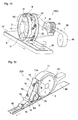
- FIG. 1 illustrates the outline of a first embodiment of the fiber stacking device of the invention.
- a fiber stacking device 100 of the first embodiment includes a rotating drum 2 that is driven to rotate in the direction of arrow R2, a duct 4 that supplies a shaped-product material to an outer peripheral surface 21 of the rotating drum 2, a transfer roller 5 that is disposed obliquely below the rotating drum 2 and is driven to rotate in the direction of arrow R5, a vacuum conveyor 6 that is arranged below the transfer roller 5, and a cutter 7.
- the fiber stacking device 100 is further provided with a vacuum box 11 that is provided between the duct 4 and the transfer roller 5 in a circumferential direction of the rotating drum 2, a mesh belt 13 that is arranged so as to pass between the vacuum box 11 and the rotating drum 2 and between the transfer roller 5 and the rotating drum 2, and windshield plates 15 that are provided close to the outer peripheral surface of the transfer roller 5.
- the vacuum box 11 and the windshield plates 15 are means for stably transferring a fiber stack, which is present in a collecting/stacking recess 22, without causing the fiber stack to lose its shape.
- a fiber stack which is relatively less likely to lose its shape like a fiber stack 32 illustrated in Fig.
- a fiber stack 32A illustrated in Fig. 11 includes recesses (grooves) 38 that have the shape of a lattice in planar view and protrusions 39 that are formed at the respective cells of the lattice, and is a fiber stack that is relatively likely to lose its shape.
- the vacuum box 11 and the windshield plates 15 are effective.
- the rotating drum 2 is formed in a cylindrical shape as illustrated in Fig. 1 , and rotates about a horizontal axis by receiving power from a prime mover, such as a motor.
- the rotating drum 2 includes collecting/stacking recesses 22 which are formed on the outer peripheral surface 21 thereof and in which a shaped-product material are stacked.
- the plurality of recesses 22 are formed at a predetermined interval in the circumferential direction of the rotating drum 2 (a 2X direction).
- the 2X direction is the circumferential direction of the rotating drum 2
- a 2Y direction is a width direction of the rotating drum 2 (a direction parallel to the rotation axis of the rotating drum 2).
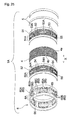
- the rotating drum 2 includes a cylindrical drum body (not illustrated) that is formed of a metallic rigid body, a suction adjusting plate 25 that is fixed so as to overlap an outer peripheral portion of the drum body, a space plate 26 that is fixed so as to overlap an outer surface 25a side of the suction adjusting plate 25, a porous plate 27 (a porous member) that is fixed so as to overlap an outer surface 26a side of the space plate 26, and a pattern forming plate 28 that is fixed so as to overlap an outer surface 27a side of the porous plate 27.
- These plates 25 to 28 are fixed to the drum body by known fixing means, such as bolts or an adhesive.
- the outer surfaces of the respective components (the suction adjusting plate 25, the space plate 26, the porous plate 27, the pattern forming plate 28, and the like) of the rotating drum 2 are the surfaces of the components that face the supply side of a shaped-product material when the shaped-product material is stacked.
- the inner surfaces of the respective components are the surfaces of the components that face the side opposite to the supply side of a shaped-product material (the inside of the rotating drum) when the shaped-product material is stacked.
- a shaped product manufactured by the fiber stacking device 100 is an absorbent member used for an absorbent article, such as a disposable diaper or a sanitary napkin
- the shaped-product material is an absorbent-core material.
- the shaped-product material contains a fiber material.
- Various materials which have been conventionally used for absorbent members of absorbent articles, such as a sanitary napkin or a panty liner and a disposable diaper, can be used as the shaped-product material, which serves as the absorbent-core material, without particular limitation.
- pulp fiber such as fibrillated pulp, short fiber of cellulosic fiber, such as rayon fiber and cotton fiber, short fiber of synthetic fiber such as polyethylene, and the like are used.
- One of these fiber materials can be used alone or the combination of two or more thereof can be used.
- a water-absorbent polymer and a fiber material may be used together as the absorbent-core material.
- a fibrous material a fibrous water-absorbent polymer can be used alone or can be used together with a fiber material.
- a deodorizer, an antimicrobial agent, or the like can also be used together with a fiber material or the like, as necessary.
- the pattern forming plate 28 includes an outer surface 28a that forms the outer peripheral surface 21 of the rotating drum 2 and an inner surface 28b that faces the rotation-axis side of the rotating drum 2, and includes a space portion that is formed between the outer surface 28a and the inner surface 28b and has a shape corresponding to the three-dimensional shape of the collecting/stacking recess 22. Portions of the pattern forming plate 28 except for the space portion have air impermeability where air does not pass.
- air impermeability includes both of “air impermeability where air does not pass completely” and “sparing air permeability where minute amount of air passes but air does not pass substantially” and means a substantially air-impermeable property.
- a plate in which an opening (a space portion having a shape corresponding to the three-dimensional shape of the recess 22) is formed by performing machining on a plate made of metal, such as stainless steel or aluminum, or a resin, a plate in which the opening is integrally formed by using a mold, a plate that has been subjected to punching or etching, a plate in which these plates overlap, or the like can be used as the pattern forming plate 28.
- the porous plate 27 is an air-permeable plate which conveys an air stream (vacuum air), which is generated by suction from the inside of the device (the inside of the rotating drum 2), to the outside of the device (the outside of the rotating drum 2), holds a shaped-product material carried on the air stream without allowing the shaped-product material to pass therethrough, and allows only air to pass therethrough.
- a plurality of (many) suction holes (fine holes), which penetrate the plate 27 in a thickness direction, are formed with a uniform distribution in the entire porous plate 27, and the suction holes function as transmission holes for an air stream while the collecting/stacking recess 22 passes over a space in the rotating drum 2 that is maintained at negative pressure.
- a mesh plate that is made of metal or a resin, a plate in which a plurality of (many) fine holes are formed by performing etching or punching on a plate made of metal or a resin, or the like can be used as the porous plate 27.
- an adjuster 10 which rectifies the air stream, is arranged on an inner surface 27b side of the porous plate 27 so as to overlap a part of the inner surface 27b of the plate 27.
- the adjuster 10 includes a first layer 8 and a second layer 9 that are laminated in this order from the porous plate 27.
- the adjuster 10 includes the suction adjusting plate 25 and the space plate 26.
- planar view refers to a view in which an object (the collecting/stacking recess, or the like) is viewed from the outside in a direction of a normal to the outer peripheral surface 21 of the rotating drum 2 (a direction orthogonal to the direction of the rotation axis of the rotating drum 2).
- the first layer 8 includes a plurality of first openings 81 that penetrate the first layer 8 in the thickness direction and an opening defining section 82 that partitions and forms the first openings 81.
- the opening defining section 82 includes a plurality of MD defining members 83 that extend in a transporting direction R2 of the collecting/stacking recess 22 (the circumferential direction of the rotating drum 2 and the 2X direction), and a plurality of CD defining members 84 that extend in a direction orthogonal to the transporting direction (the width direction of the rotating drum 2 and the 2Y direction).
- "extend in a transporting direction of the collecting/stacking recess” means that the MD defining members have only to extend substantially in the transporting direction, is not limited to a case in which the MD defining members have the shape of a straight line parallel to the transporting direction in a planar view of the collecting/stacking recess 22, and includes a case in which the MD defining members are formed in the shape of a curve along the transporting direction and also includes a case in which the MD defining members are not parallel to the transporting direction but extend in a direction intersecting with the transporting direction at an angle of 45° or less.
- "extend in a direction orthogonal to the transporting direction of the collecting/stacking recess (an orthogonal direction)” means that the CD defining members have only to extend substantially in the orthogonal direction, is not limited to a case in which the CD defining members have the shape of a straight line parallel to the orthogonal direction in a planar view of the collecting/stacking recess 22, and includes a case in which the CD defining members are formed in the shape of a curve along the orthogonal direction and also includes a case in which the CD defining members are not parallel to the orthogonal direction but extend in a direction intersecting with the orthogonal direction at an angle of 45° or less.
- the opening defining section 82 includes six MD defining members 83 that are parallel to the transporting direction of the collecting/stacking recess 22 (the 2X direction) and have the shape of a straight line in planar view, and five CD defining members 84 that are parallel to the direction orthogonal to the transporting direction of the collecting/stacking recess 22 (the 2Y direction) and have the shape of a straight line in planar view.
- the opening defining section 82 is formed in the shape of a lattice in planar view by a total of ten defining members 83 and 84 that have the shape of a straight line in planar view.
- the first openings 81 are positioned at the respective cells of the lattice of the lattice-shaped opening defining section 82, and have a quadrangular shape in planar view.
- the opening defining section 82 (the defining members 83 and 84) has air impermeability where air does not pass.
- air impermeability has the above-mentioned meaning.
- Metal, such as stainless steel, aluminum, or iron, a resin, or the like can be used as a material of the opening defining section 82 (the defining members 83 and 84) having air impermeability.
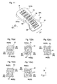
- Second openings 91 which penetrate the second layer 9 in the thickness direction, are formed at portions of the second layer 9, which overlap the plurality of first openings 81 in a planar view of the collecting/stacking recess 22 as illustrated in Fig. 2 , so as to correspond to the respective first openings 81. Accordingly, both the openings 81 and 91, which are in this correspondence, overlap each other in the planar view.
- one second opening 91 of the second layer 9 corresponds to one first opening 81 of the first layer 8. Accordingly, the first openings 81 are in one-to-one correspondence with the second openings 91.
- the second opening 91 is present at a position separated from the CD defining members 84 in each of the plurality of first openings 81 in a planar view of the collecting/stacking recess 22 as illustrated in Fig. 2 , and portions of the second layer 9 overlapping the CD defining members 84 (hereinafter, referred to as CD-defining-member corresponding sections) and the vicinity thereof have air impermeability where air does not pass.
- air impermeability has the above-mentioned meaning.
- Reference numeral 92 in Fig. 3 denotes the CD-defining-member corresponding sections of the second layer 9 and the vicinity thereof.
- the CD-defining-member corresponding sections and the vicinity thereof 92 are made of an air-impermeable material such as metal (for example, stainless steel, aluminum, or iron), or a resin, include no openings (through holes penetrating the second layer 9 in the thickness direction), and have air impermeability
- the vicinity of the CD-defining-member corresponding sections is a region that extends along one CD defining member 84 over the total length of the one CD defining member 84 in the 2Y direction (the width direction of the rotating drum 2) in a planar view of the collecting/stacking recess 22 and has a constant width (length in the 2X direction) W1 (see Fig. 4 ). Further, the width of the CD-defining-member corresponding section (the length of the CD-defining-member corresponding section in the 2X direction) is the same as the width W2 of the corresponding CD defining member 84 (see Fig. 4 ).
- the second layer 9 of the first embodiment includes air-impermeable sections through which air does not pass and which are formed at portions of the second layer 9 overlapping not only the CD defining members 84 but also the MD defining members 83 and in the vicinity thereof. That is, the second opening 91 is present at a position separated from the MD defining members 83 in each of the plurality of first openings 81 in a planar view of the collecting/stacking recess 22 as illustrated in Fig. 2 , and portions of the second layer 9 overlapping the MD defining members 83 (hereinafter, referred to as MD-defining-member corresponding sections) and the vicinity thereof have air impermeability where air does not pass.
- air impermeability has the above-mentioned meaning.
- Reference numeral 93 in Fig. 3 denotes the MD-defining-member corresponding sections of the second layer 9 and the vicinity thereof.
- the MD-defining-member corresponding sections and the vicinity thereof 93 are made of an air-impermeable material such as metal (for example, stainless steel, aluminum, or iron), or a resin, include no openings (through holes penetrating the second layer 9 in the thickness direction)and have air impermeability.
- the vicinity of the MD-defining-member corresponding sections is a region that extends along one MD defining member 83 over the total length of the one MD defining member 83 in the 2X direction (the circumferential direction of the rotating drum 2) in a planar view of the collecting/stacking recess 22 and has a constant width (length in the 2Y direction) W3 (see Fig. 4 ). Further, the width of the MD-defining-member corresponding section (the length of the MD-defining-member corresponding section in the 2Y direction) is the same as the width W4 of the corresponding MD defining member 83 (see Fig. 4 ).
- the second opening 91 is present at a position, which is separated from two CD defining members 84 and 84 facing each other and two MD defining members 83 and 83 facing each other, in each of the plurality of first openings 81 in a planar view of the collecting/stacking recess 22. Accordingly, the area of the second opening 91, which is present in one first opening 81 in a planar view of the recess 22, is smaller than that of the first opening 81.
- the "areas" of both the openings 81 and 91 mean the areas of opening end portions of the openings (the first opening 81 and the second opening 91) that are closest to the porous plate 27 (the areas of portions of the openings coming into contact with the porous plate when the openings come into contact with the porous plate).
- the first and second openings 81 and 91 overlap each other in a planar view of the collecting/stacking recess 22. Accordingly, it can be said that one opening, which penetrates the adjuster 10 (the first layer 8 and the second layer 9) in the thickness direction, is formed of both the openings 81 and 91 overlapping each other. Further, the area of the second opening 91, which is present in one first opening 81 in a planar view of the recess 22, is smaller than that of the first opening 81 as described above.
- the adjuster 10 of the first embodiment includes a plurality of openings (openings formed of the first and second openings 81 and 91 that overlap each other in a planar view of the recess 22) penetrating the adjuster 10 in the thickness direction and the area of the opening end portion of the opening relatively distant from the porous plate 27 (the opening end portion of the second opening 91) is smaller than the area of the opening end portion thereof relatively close to the porous plate 27 (the opening end portion of the first opening 81).
- the second opening 91 is formed at the center of each of the plurality of first openings 81 in a planar view of the collecting/stacking recess 22.
- the shape of one first opening 81 in planar view and the shape of a second opening 91, which is present in the first opening 81, in planar view are similar to each other, and both the openings 81 and 91 have a quadrangular shape in planar view. That is, the ratio of similitude of the second opening 91 to the corresponding first opening 81 is lower than 1 in terms of planar-view shape of the openings 81 and 91.
- the adjuster 10 (the first and second layers 8 and 9) having the above-mentioned structure is arranged on the inner surface 27b side of the porous plate 27 that forms the bottom surface 22a of the collecting/stacking recess 22, the volume of air, which is obtained when an air stream (vacuum air) generated by suction from the inside of the device and sucking a shaped-product material flows through the porous plate 27, is reduced as compared to a case where the adjuster 10 is not arranged as in an adjuster-non-arrangement region (a high basis-weight fiber-stack region) 23 of the recess 22 to be described below. That is, as illustrated in Fig. 5 , the air stream (illustrated by arrows in Fig.
- the basis weight of the shaped-product material depends on the volume of air flowing through the porous plate 27. Accordingly, it is possible to manufacture a shaped product, of which the basis weight of a desired portion is reduced, with simple facilities by arranging the adjuster 10 in a region, which corresponds to a portion in which the basis weight of a shaped-product material to be stacked is intended to be smaller than those of other portions, of the inner surface 27b side of the porous plate 27.
- an absorbent member used for an absorbent article such as a disposable diaper or a sanitary napkin
- an absorbent member which is excellent in both absorption performance and the reduction of inconvenience and discomfort in wearing, by concentrately stacking an absorbent-core material, such as pulp or a water-absorbent polymer, on a portion requiring high absorption capacity and reducing the basis weight of the other portions as much as possible by using the adjuster 10.
- the first openings 81 are provided on the windward side of the second opening 91 on the air stream.
- a plurality of spaces (spaces B to D) partitioned from one another are formed in the rotating drum 2, a part (the space B) of the plurality of spaces is maintained at negative pressure, the collecting/stacking recess 22 is transported in an R2 direction by the rotation of the rotating drum 2 in the R2 direction, and an air stream flows through the bottom surface 22a of the recess 22 toward the inside from the outside of the drum while the collecting/stacking recess 22 passes over the space B maintained at negative pressure.
- the plurality of first openings 81 communicate with one another so that an air stream can flow in the transporting direction R2 of the recess 22 (the circumferential direction of the rotating drum 2 and the 2X direction) through the second openings 91 overlapping the CD defining members 84 or the air-permeable sections.
- the second opening 91 is present at a position, which is separated from the CD defining members 84, in each of the plurality of first openings 81 in a planar view of the collecting/stacking recess 22, and the CD-defining-member corresponding sections of the second layer 9 and the vicinity thereof 92 form the air-impermeable sections through which air does not pass.
- the plurality of first openings 81 do not communicate with one another so that an air stream cannot flow in the transporting direction R2 of the recess 22. For this reason, before the rear first openings 81 pass over a space of the rotating drum 2 maintained at negative pressure, turbulence is not generated in the rear first openings 81. Therefore, a rectification effect obtained from the above-mentioned first openings 81 is reliably achieved.
- the second openings 91 are present at positions that are separated from not only the CD defining members 84 but also the MD defining members 83 extending in a direction orthogonal to the CD defining members 84, and the portions of the second layer 9 overlapping the opening defining sections 82 and the vicinity thereof (92, 93) form air-impermeable sections.
- the plurality of first openings 81 do not communicate with one another so that an air stream cannot flow in both the transporting direction R2 of the collecting/stacking recess 22 and a direction orthogonal to the transporting direction R2, and the independence of the space formed by each of the respective first openings 81 is ensured. Therefore, a rectification effect obtained from the above-mentioned first openings 81 is achieved more reliably.
- the second opening 91 is formed at the center of each of the plurality of first openings 81 in a planar view of the collecting/stacking recess 22 and the shape of one first opening 81 in planar view and the shape of the second opening 91, which is present in the first opening 81, in planar view are similar to each other in a planar view of the recess 22.
- the structure of these openings is effective in stably achieving a rectification effect obtained from the above-mentioned first openings 81.
- the width W1 (see Fig. 4 ) of a portion of the second layer 9 in the vicinity of the CD-defining-member corresponding section is preferably 1 mm or greater and more preferably 2 mm or greater, and preferably 10 mm or less and more preferably 5 mm or less. More specifically, the width W1 of a portion of the second layer 9 in the vicinity of the CD-defining-member corresponding section is preferably in the range of 1 to 10 mm and more preferably in the range of 2 to 5 mm.
- the width W2 (see Fig. 4 ) of the CD defining member 84 of the first layer 8 is preferably 0.5 mm or greater and more preferably 1 mm or greater, and preferably 5 mm or less and more preferably 2 mm or less. More specifically, the width W2 (see Fig. 4 ) of the CD defining member 84 is preferably in the range of 0.5 to 5 mm and more preferably in the range of 1 to 2 mm.
- the width W3 (see Fig. 4 ) of a portion of the second layer 9 in the vicinity of the MD-defining-member corresponding section is preferably 1 mm or greater and more preferably 2 mm or greater, and preferably 10 mm or less and more preferably 5 mm or less. More specifically, the width W3 of a portion of the second layer 9 in the vicinity of the MD-defining-member corresponding section is preferably in the range of 1 to 10 mm and more preferably in the range of 2 to 5 mm.
- the width W4 (see Fig. 4 ) of the MD defining member 83 of the first layer 8 is preferably 0.5 mm or greater and more preferably 1 mm or greater, and preferably 5 mm or less and more preferably 2 mm or less. More specifically, the width W4 of the MD defining member 83 is preferably in the range of 0.5 to 5 mm and more preferably in the range of 1 to 2 mm.
- the length W5 (see Fig. 2 ) of the first opening 81 in the 2X direction is preferably 5 mm or greater and more preferably 10 mm or greater, and preferably 30 mm or less and more preferably 25 mm or less. More specifically, the length W5 of the first opening 81 in the 2X direction is preferably in the range of 5 to 30 mm and more preferably in the range of 10 to 25 mm.
- the length W6 (see Fig. 2 ) of the first opening 81 in the 2Y direction is preferably 5 mm or greater and more preferably 10 mm or greater, and preferably 20 mm or less and more preferably 15 mm or less. More specifically, the length W6 of the first opening 81 in the 2Y direction is preferably in the range of 5 to 20 mm and more preferably in the range of 10 to 15 mm.
- the length W7 (see Fig. 2 ) of the second opening 91 in the 2X direction is preferably 2 mm or greater and more preferably 5 mm or greater, and preferably 30 mm or less and more preferably 25 mm or less. More specifically, the length W7 of the second opening 91 in the 2X direction is preferably in the range of 2 to 30 mm and more preferably in the range of 5 to 25 mm.
- the length W8 (see Fig. 2 ) of the second opening 91 in the 2Y direction is preferably 2 mm or greater and more preferably 5 mm or greater, and preferably 20 mm or less and more preferably 15 mm or less. More specifically, the length W8 of the second opening 91 in the 2Y direction is preferably in the range of 2 to 20 mm and more preferably in the range of 5 to 15 mm.
- a ratio (S2/S1) of the area S2 of the second opening 91 to the area S1 of the first opening 81 is preferably in the range of 5 to 50% and more preferably in the range of 7 to 15%.
- the thickness T (see Fig. 5 ) of the opening defining section 82 (the MD defining member 83 and the CD defining member 84) of the first layer 8 is preferably 2 mm or greater and more preferably 3 mm or greater, and preferably 10 mm or less and more preferably 5 mm or less. More specifically, the thickness T of the opening defining section 82 is preferably in the range of 2 to 10 mm and more preferably in the range of 3 to 5 mm.
- the adjuster 10 (the first and second layers 8 and 9) is not arranged so as to correspond to the entire region of the porous plate 27, is arranged only in a region, which corresponds to the rear portion of the collecting/stacking recess 22 in the transporting direction R2, of the inner surface 27b side of the porous plate 27 as illustrated in Fig. 2 , and is not arranged in the other regions including the front portion of the porous plate 27.
- the collecting/stacking recess 22 includes an adjuster-arrangement region 24 where the adjuster 10 is arranged on the inner surface 27b side of the porous plate 27 forming the bottom surface 22a of the recess 22 and the adjuster-non-arrangement region 23 where the adjuster 10 is not arranged on the inner surface 27b side of the porous plate 27.
- a first large opening 85 which penetrates the space plate 26 in the thickness direction and has an area larger than the area of the first opening 81 and a rectangular shape in planar view, is formed at a portion of the space plate 26 except for the first layer 8
- a second large opening 95 which penetrates the suction adjusting plate 25 in the thickness direction and has a rectangular shape in planar view, is formed at the suction adjusting plate 25 so as to correspond to the first large opening 85.
- the shapes of both the openings 85 and 95 in planar view are congruent with each other, and a ratio of similitude of the second large opening 95 to the first large opening 85 is 1.
- each of both the openings 85 and 95 have a size overlapping the entire adjuster-non-arrangement region 23 of the recess 22 in a planar view of the collecting/stacking recess 22, substantially the entire region of the inner surface 27b of the porous plate 27 corresponds to both the openings 85 and 95 as illustrated in Fig. 6 in the adjuster-non-arrangement region 23. Accordingly, in the adjuster-non-arrangement region 23 of the recess 22, air permeability inherent in the porous plate 27 is not inhibited and the volume of air of an air stream (vacuum air), which is generated by suction from the inside of the device and sucks a shaped-product material, is not reduced.
- an air stream vacuum air
- the shaped-product material is stacked in the adjuster-non-arrangement region 23 with a basis weight that is higher than the basis weight of the shaped-product material stacked in the adjuster-arrangement region 24 of the recess 22.
- the collecting/stacking recess 22 of the first embodiment includes the adjuster-non-arrangement region (the high basis-weight fiber-stack region) 23 in which a shaped-product material is stacked with a relatively high basis weight, and the adjuster-arrangement region (a low basis-weight fiber-stack region) 24 in which a shaped-product material is stacked with a relatively low basis weight, and the adjuster-non-arrangement region (the high basis-weight fiber-stack region) 23 and the adjuster-arrangement region (the low basis-weight fiber-stack region) 24 are arranged in the transporting direction R2 (a longitudinal direction) of the recess 22 (see Fig. 2 ).
- the adjuster 10 is not arranged on the inner surface 27b side of the porous plate 27 forming the bottom surface 22a of the collecting/stacking recess 22.
- the adjuster 10 is arranged on the inner surface 27b side of the porous plate 27.
- the fiber stacking device 100 of the first embodiment will be further described.
- the spaces B, C, and D which are partitioned from one another in the circumferential direction of the rotating drum 2 (the 2X direction), are formed on the inside (rotation-axis side) of the rotating drum 2.
- a known exhaust device (not illustrated), such as an air-suction fan, is connected to the space B, and the space B can be maintained at negative pressure through the actuation of the exhaust device. Outside air flows into the space C by suction from the vacuum box 11 to be described below, and outside air flows into the space D by suction from the transfer roller 5.
- the space C is divided from the space D that corresponds to a region having been subjected to transfer.
- the rotating drum 2 may include means for generating blow (air stream), which is directed to the bottom surface 22a of the recess 22 (the porous plate 27) from the inside of the rotating drum 2, in a space (a space C) corresponding to a transfer position where the fiber stack present in the recess 22 is transferred onto the transfer roller 5.
- blow air stream
- one end of the rotating drum 2 in the direction of the rotation axis of the rotating drum 2 is closed by a plate that rotates integrally with the rotating drum 2, and the other end thereof is airtightly closed by a plate that does not rotate. Further, the spaces B to D are partitioned from one another by plates that are provided from the rotation-axis side of the rotating drum 2 toward the inner surface of the rotating drum 2.
- the pressure of the space C is generally set to negative pressure, which is lower than the pressure of the space B, or zero pressure (atmospheric pressure).
- negative pressure which is lower than the pressure of the space B
- zero pressure atmospheric pressure.
- the space C be maintained at low negative pressure and the fiber stack be sucked and held in the recess 22.
- the space C be maintained at zero pressure in consideration of a transfer property.
- the space D is a region over which the recess 22 passes after the fiber stack present in the recess 22 is transferred onto the transfer roller 5, it is preferable that the space D be maintained at zero pressure or positive pressure.
- one end side of the duct 4 covers the outer peripheral surface of the rotating drum 2 positioned on the space B, and the duct 4 includes a shaped-product material introduction device on the other side thereof (not illustrated).
- the shaped-product material introduction device includes, for example, a pulverizer that pulverizes a wood pulp sheet into fibrillated pulp and sends the fibrillated pulp (a fiber material) into the duct 4.
- a water-absorbent polymer introduction unit, which introduces water-absorbent polymer particles, may be provided on the duct 4.
- the transfer roller 5 has an air-permeable cylindrical outer peripheral portion, and the outer peripheral portion rotates about a horizontal axis by receiving power from a prime mover, such as a motor.
- a space E of which inside pressure can be reduced is formed in the non-rotating section inside the transfer roller 5 (the rotation-axis side).
- a known exhaust device (not illustrated), such as an air-suction fan, is connected to the space E, and the space E can be maintained at negative pressure through the actuation of the exhaust device.
- a plurality of (many) suction holes for communication between the inside and the outside of the transfer roller are formed in the outer peripheral surface of the transfer roller 5. While passing over the space E maintained at negative pressure, the suction holes suck air to the inside from the outside and the fiber stack present in the recess 22 is smoothly transferred from the rotating drum 2 onto the transfer roller 5 by this suction force of the air.
- the vacuum conveyor 6 includes an endless air-permeable belt 63 that is spanned between a drive roller 61 and driven rollers 62 and 62, and a vacuum box 64 that is arranged at a position facing the transfer roller 5 across the air-permeable belt 63.
- the vacuum box 11 has a box-like shape having upper and lower surfaces, left and right side surfaces, and a rear surface, and includes an opening that opens toward the rotating drum 2.
- a known exhaust device such as an air-suction fan, is connected to the vacuum box 11 through an exhaust pipe (not illustrated), and the inside of the vacuum box 11 can be maintained at negative pressure through the actuation of the exhaust device.
- the mesh belt 13 is a member that is formed by endlessly connecting a band-shaped air-permeable belt having meshes, and moves continuously along a predetermined route by being guided by a plurality of free rollers 14 and the transfer roller 5. The mesh belt 13 is driven by the rotation of the transfer roller 5. As illustrated in Fig.
- the mesh belt 13 is arranged so as to sequentially pass between the vacuum box 11 and the rotating drum 2 and between the transfer roller 5 and the rotating drum 2 after being introduced onto the outer peripheral surface of the rotating drum 2 in the vicinity of a downstream end 41 of the duct 4.
- the mesh belt 13 comes into contact with the outer peripheral surface of the rotating drum 2 while passing the front of the opening of the vacuum box 11, and the mesh belt is separated from the outer peripheral surface of the rotating drum 2 and moves onto the transfer roller 5 in the vicinity of a portion where the transfer roller 5 and the rotating drum 2 come nearest to each other.
- the mesh belt 13 includes fine holes that are smaller than the suction holes of the transfer roller 5, and suction from the fine holes of the mesh belt 13, which overlap the suction holes of the transfer roller 5, is also performed with suction from the suction holes of the transfer roller 5.
- the pair of windshield plates 15 is provided on both sides of a region, in which the suction holes are formed, of the outer peripheral surface of the transfer roller 5 in the width direction. The windshield plates 15 prevent the fiber stack, which has been released from the recess 22, from losing its shape by preventing or reducing the inflow of air from the sides.
- the material of the windshield plate 15 is not particularly limited, but it is preferable that the material of the windshield plate 15 be metal or a synthetic resin and the thickness of the windshield plate 15 be in the range of about 0.5 to 10 mm from the viewpoint of stiffness capable of resisting air.
- the cutter 7 illustrated in Fig. 1 includes a cutter roller 72 that includes cutting blades 71 on the peripheral surface thereof and an anvil roller 73 which receives the cutting blades and of which the peripheral surface is smooth.
- the manufacturing method of this embodiment includes a fiber stacking step of sucking and stacking an absorbent-core material (a shaped-product material), which is supplied on an air stream, in the collecting/stacking recess 2 of the rotating drum 2 in the fiber stacking device 100.
- an absorbent-core material a shaped-product material
- the pressure of the space B formed in the rotating drum 2, the pressure of the space E formed in the transfer roller 5, and the inside pressure of the vacuum box 11 are reduced to negative pressure through the actuation of the exhaust devices connected thereto.
- an air stream vacuum air
- the vacuum conveyor 6 is actuated by the rotation of the rotating drum 2 and the transfer roller 5.
- the absorbent-core material floats on the air stream flowing in the duct 4 and is supplied toward the outer peripheral surface 21 of the rotating drum 2 in a dispersed airborne state.
- An air stream for transporting the absorbent-core material, which is introduced from the shaped-product material introduction device or the water-absorbent polymer introduction unit, onto the outer peripheral surface 21 of the rotating drum 2 is generated in the duct 4 by suction from the suction holes of the porous plate 27 forming the bottom surface 22a; and the absorbent-core material transported on the air stream is stacked in the recess 22.
- the amount of absorbent-core material to be stacked in the recess 22 is set to be different according to whether or not the adjuster 10 is arranged.
- the absorbent-core material is stacked in the adjuster-non-arrangement region (the high basis-weight fiber-stack region) 23 with a relatively high basis weight and is stacked in the adjuster-arrangement region (the low basis-weight fiber-stack region) 24 with a relatively low basis weight (see Fig. 2 ).
- the adjuster-non-arrangement region 23 is completely covered with the absorbent-core material and the adjuster-arrangement region 24 is not completely covered with the absorbent-core material.
- a difference in level which is caused by a difference in the stacked amount of the absorbent-core material, is formed at a boundary portion between the adjuster-non-arrangement region 23 and the adjuster-arrangement region 24 on the surface of the fiber stack that is present in the recess 22 (the surface of the fiber stack that is opposite to the surface of the fiber stack coming into contact with the bottom surface 22a of the recess 22). Accordingly, the surface of the adjuster-arrangement region 24 is present at a position lower than the surface of the adjuster-non-arrangement region 23.
- the rotating drum 2 is further rotated. Further, when the fiber stack 32 present in the recess 22 reaches a position facing the vacuum box 11, the fiber stack 32 is sucked onto the mesh belt 13 by suction from the vacuum box 11. In this state, the fiber stack 32 is transported to a portion where the transfer roller 5 and the rotating drum 2 come nearest to each other or to the vicinity thereof. Then, the fiber stack 32, which has been sucked onto the mesh belt 13, is released from the recess 22 by suction from the transfer roller 5, and is transferred onto the transfer roller 5 together with the mesh belt 13.
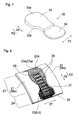
- Fig. 7 illustrates the fiber stack 32 that has just been released from the collecting/stacking recess 22 of the first embodiment.
- a portion of the fiber stack 32 corresponding to the adjuster-non-arrangement region (the high basis-weight fiber-stack region) 23 of the recess 22 is a high basis-weight section (a thick section) 33 in which the stacked amount of the absorbent-core material is relatively large
- a portion of the fiber stack 32 corresponding to the adjuster-arrangement region (the low basis-weight fiber-stack region) 24 of the recess 22 is a low basis-weight section (a thin section) 34 in which the stacked amount of the absorbent-core material is relatively small.
- the entire one surface 32b of the fiber stack 32 (the surface of the fiber stack 32 coming into contact with the bottom surface 22a of the recess 22) is substantially flat.
- the other surface 32a (the surface of the fiber stack 32 that is opposite to the surface of the fiber stack 32 coming into contact with the bottom surface 22a of the recess 22) has a difference in level at a boundary portion between the high basis-weight section 33 and the low basis-weight section 34, and the other surface 32a is not flat.
- the fiber stack 32 transferred onto the transfer roller 5 is transported while being sucked from the transfer roller 5, and is then passed on to a core-wrap sheet 37 that has been introduced onto the vacuum conveyor 6 arranged below the transfer roller 5 and is made of tissue paper, liquid-permeable nonwoven fabric, or the like.
- a core-wrap sheet 37 that has been introduced onto the vacuum conveyor 6 arranged below the transfer roller 5 and is made of tissue paper, liquid-permeable nonwoven fabric, or the like.
- both side portions of the core-wrap sheet 37 extending in the transporting direction are folded back, and both the upper and lower surfaces of the fiber stack 32 are covered with the core-wrap sheet 37.
- the fiber stack 32, which is covered with the core-wrap sheet 37 is cut to a predetermined size together with the core-wrap sheet 37 by the cutter roller 72 of the cutter 7.
- an absorbent member 3 covered with the core-wrap sheet 37 is obtained.
- the absorbent member 3 is an absorbent member which includes the high basis-weight section 33 and the low basis-weight section 34 and in which the stacked amount of the absorbent-core material is partially different.
- the high basis-weight section 33 is stacked in the adjuster-non-arrangement region (the high basis-weight fiber-stack region) 23 of the recess 22 and has a relatively high basis weight
- the low basis-weight section 34 is stacked in the adjuster-arrangement region (the low basis-weight fiber-stack region) 24 and has a relatively low basis weight.
- the absorbent member 3 constitutes a high-quality absorbent member suitable as an absorbent member used for absorbent articles, such as disposable diapers, sanitary napkins, and incontinence pads.
- the absorbent member 3 which is built in an absorbent article so that the high basis-weight section 33 of the absorbent member 3 forms a ventral (front) portion of the absorbent article and the low basis-weight section 34 forms a dorsal (rear) portion of the absorbent article, be used as an absorbent member used for a disposable diaper.
- the high basis-weight section and the low basis-weight section having different basis weights are formed in the absorbent member as described above, an advantage of obtaining an absorbent member which is flexible and of which a wearing feeling is improved, and the like are obtained.
- an absorbent member in which low basis-weight sections are formed on the front and rear of or around a high basis-weight section is flexible and is excellent in a wearing feeling.
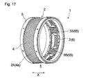
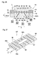
- Fig. 8 illustrates a main part of a second embodiment of the fiber stacking device of the invention
- Fig. 9 illustrates an exploded perspective view of the main part.
- a recess partitioning member 35 which partitions a collecting/stacking recess 22A into a plurality of regions in a direction parallel to a bottom surface 22a, is arranged so as to overlap at least a part of an outer surface 27a of a porous plate 27 that forms the bottom surface 22a of the collecting/stacking recess 22A.
- a space plate 26A of the second embodiment includes a narrow section 29 and a wide section arranged in the 2X direction (the circumferential direction of the rotating drum 2).
- the narrow section 29 has a relatively short length (width) in the 2Y direction (the width direction of the rotating drum 2), and the wide section has a relatively long length (width) in the 2Y direction.
- the wide section forms the first layer 8 of the adjuster 10.
- the narrow section 29 is formed in the shape of a lattice so as to have the same opening pattern as that of the first layer 8 (the wide section), and includes a plurality of (many) openings 81 A that have the same shape and dimensions as those of a first opening 81 of the first layer 8.
- the narrow section 29 has a rectangular shape in planar view, and is positioned at the middle of the space plate 26A in the 2Y direction. The entire narrow section 29 overlaps the second large opening 95 of the suction adjusting plate 25 in a planar view of the collecting/stacking recess 22A.
- the recess partitioning member 35 includes a plurality of openings 36 that penetrate the recess partitioning member 35 in the thickness direction, and an opening defining section 37 that partitions and forms the openings 36.
- the opening defining section 37 is formed in the shape of a lattice in planar view.
- the respective openings 36 are positioned at the respective cells of the lattice of the lattice-shaped opening defining section 37, and have a quadrangular shape in planar view.
- the opening defining section 37 has air impermeability where air does not pass.
- air impermeability has the above-mentioned meaning.
- the opening defining section 37 has a rectangular shape in planar view, and is arranged at the middle portion of the bottom surface 22a of the collecting/stacking recess 22A in the 2Y direction so that the longitudinal direction of the opening defining section 37 corresponds to the 2X direction.
- the total length of the recess partitioning member 35 in the 2X direction is shorter than that of the space plate 26A in the 2X direction, and the length (width) of the recess partitioning member 35 in the 2Y direction is the same as that of the narrow section 29 of the space plate 26A in the 2Y direction.
- the opening pattern of the recess partitioning member 35 is the same as that of the space plate 26A [the narrow section 29, and the first layer (the wide section)], and the shapes and dimensions of the openings 36 are the same as those of the openings 81 and 81A of the space plate 26A.
- the recess partitioning member 35 is fixed onto the outer surface 27a of the porous plate 27 by known fixing means, such as bolts or an adhesive, so as to completely correspond to the narrow section 29 in a planar view of the collecting/stacking recess 22A.
- one opening 36 of the recess partitioning member 35 is in one-to-one correspondence with one opening 81A of the narrow section 29 of the space plate 26A at a part (a middle portion thereof in the 2Y direction) of an adjuster-non-arrangement region (the high basis-weight fiber-stack region) 23, in which the adjuster 10 is not arranged and a shaped-product material is stacked with a relatively high basis weight, of the collecting/stacking recess 22A. Further, as illustrated in Fig.
- one opening 36 of the recess partitioning member 35 is in one-to-one correspondence with each of one first opening 81 of the first layer 8 (the wide section) of the space plate 26A and one second opening 91 of the second layer 9 of the suction adjusting plate 25 in an adjuster-arrangement region (the low basis-weight fiber-stack region) 24 in which the adjuster 10 is arranged and a shaped-product material is stacked with a relatively low basis weight.
- the openings 36 of the recess partitioning member 35 and openings, which penetrate the adjuster 10 in the thickness direction, overlap each other in a planar view of the recess 22.
- the fiber stacking device of the second embodiment which includes the rotating drum including the collecting/stacking recesses 22A having the above-mentioned structure, can be used in the same manner as the above-mentioned fiber stacking device of the first embodiment, and can continuously manufacture absorbent members according to the above-mentioned manufacturing method. While the recess 22A passes over the space B (see Fig.
- suction from the bottom surface 22a is performed as usual at portions of the bottom surface 22a of the recess 22A that correspond to the openings 36 of the recess partitioning member 35, but suction from the bottom surface 22a is not performed at a portion of the bottom surface 22a that corresponds to the opening defining section 37 of the recess partitioning member 35 (a portion of the bottom surface 22a coming into contact with the opening defining section 37) since the opening defining section 37 has air impermeability.
- an absorbent-core material is stacked not only in the opening 36 but also on the opening defining section 37.
- the absorbent-core material On the upstream side of a duct 4, the absorbent-core material is stacked only in the openings 36, but the absorbent-core material starts to be also stacked on the opening defining section 37 in accordance with the intertwining among pieces of the absorbent-core material and the flow of air, which is present in the duct 4 and transports the absorbent-core material, when the height of the stacked absorbent-core material reaches the thickness of the opening defining section 37 (the recess partitioning member 35).
- the opening defining section 37 is completely covered with the absorbent-core material.
- Fig. 11 illustrates the fiber stack 32A that has just been released from the collecting/stacking recess 22A in the above-mentioned manufacturing method.
- a portion of the fiber stack 32A corresponding to the adjuster-non-arrangement region (the high basis-weight fiber-stack region) 23 of the recess 22A constitutes a high basis-weight section (a thick section) 33 in which the stacked amount of the absorbent-core material is relatively large
- a portion of the fiber stack 32A corresponding to the adjuster-arrangement region (the low basis-weight fiber-stack region) 24 of the recess 22A constitutes a low basis-weight section (a thin section) 34 in which the stacked amount of the absorbent-core material is relatively small.
- a plurality of grooves (recesses) 38 which extend in both the 2X direction and the 2Y direction and have the shape of continuous straight lines in planar view, are arranged in the shape of a lattice on one surface 32Ab of the fiber stack 32A (the surface of the recess 22A coming into contact with the bottom surface 22a) so as to correspond to the lattice-shaped opening defining section 37 of the recess partitioning member 35, and protrusions 39, which have a quadrangular shape in planar view, are arranged at cells of the lattice so as to correspond to the plurality of openings 36 of the recess partitioning member 35.
- one surface 32Ab includes a projecting-and-recessed section with large undulations.
- a region of one surface 32Ab on which the projecting-and-recessed section including the grooves 38 and the protrusions 39 is not formed is substantially flush with the tops of the protrusions 39.
- the other surface 32Aa of the fiber stack 32 (the surface of the fiber stack 32A that is opposite to the surface of the fiber stack 32A coming into contact with the bottom surface 22a of the recess 22A) has a difference in level at a boundary portion between the high basis-weight section 33 and the low basis-weight section 34 like the other surface 32a of the fiber stack 32 illustrated in Fig. 7 , and the other surface 32Aa is not flat.
- the fiber stack 32A includes the thick section (a high basis-weight section) 33 and the thin section (a low basis-weight section) 34 formed according to whether or not the adjuster 10 is arranged, and includes the projecting-and-recessed section, which includes the protrusions 39 (high basis-weight section) and the grooves 38 (a low basis-weight section) and corresponds to the opening pattern of the recess partitioning member 35, on one surface 32Ab of each of the thick section 33 and the thin section 34 (the surface of each of the thick section 33 and the thin section 34 coming into contact with the bottom surface 22a of the recess 22A).
- the absorbent member including the projecting-and-recessed section an absorbent member having a surface that is not flat
- the thickness of the absorbent member particularly, the thickness of the protrusions (a high basis-weight section) is actively reduced, a difference and/or a ratio between the thickness of the protrusion (a high basis-weight section) and the thickness of the groove (a low basis-weight section) is reduced. Accordingly, the absorbent member in which the protrusions (high basis-weight section) constitute a high-density section and the grooves (a low basis-weight section) constitute a low-density section is obtained.
- the absorbent member in which density is partially different allows body fluid to quickly pass through the low-density section and allows the high-density section to absorb and hold body fluid, the absorption performance of the absorbent member is improved. Further, since fiber-stacking irregularity does not occur in the fiber stack 32A (particularly, the low basis-weight section 34) due to the operation of the above-mentioned adjuster 10, the fiber stack 32A can be suitably used as an absorbent member used for absorbent articles, such as disposable diapers, sanitary napkins, and incontinence pads.
- one first opening 81 of the first layer 8 has corresponded to one second opening 91 of the second layer 9 in the above-mentioned embodiments (the first and second embodiments) so that the first openings 81 are in one-to-one correspondence with the second openings 91.
- the plurality of second openings 91 of the second layer 9 may correspond to one first opening 81 of the first layer 8.
- a plurality of second openings 91 having a circular shape in planar view correspond to one first opening 81 having a rectangular shape in planar view.
- Figs. 12(a) to 12(c) a plurality of second openings 91 having a circular shape in planar view correspond to one first opening 81 having a rectangular shape in planar view.
- a plurality of second openings 91 having a rectangular shape in planar view correspond to one first opening 81 having a rectangular shape in planar view. Accordingly, the shape of the first opening 81 in planar view is not similar to the shape of the second opening 91, which corresponds to the first opening 81, in planar view in any embodiment illustrated in Fig. 12 .
- a hatched portion is an air-impermeable section through which air does not pass. Meanwhile, for easy description, the porous plate 27 is not illustrated in Fig. 12 .
- a plurality of second openings 91 correspond to one first opening 81 as in the embodiments illustrated in Fig. 12
- each second opening 91 is present at the position separated from both the CD defining members 84 and the MD defining members 83, and the portions of the second layer 9 overlapping both the defining members 83 and 84 and the vicinity thereof (92, 93) form air-impermeable sections in the above-mentioned first and second embodiments, but at least each second opening 91 may be positioned at a position separated from the CD defining members 84, and at least the portions of the second layer 9 overlapping the CD defining members 84 and the vicinity thereof may form air-impermeable sections in the invention.
- each second opening 91 may continue so as to cross over the plurality of first openings 81 in the 2Y direction as illustrated in Fig. 13 .
- each of the plurality of second openings 91 continue over substantially the total length of the recess 22 in the 2Y direction.
- the plurality of first openings 81 communicate with one another so that an air flow can flow in the 2Y direction through the second openings 91 continuing in the 2Y direction.
- the adjuster according to the invention only has to include a plurality of openings that penetrate the adjuster in the thickness direction, and the area of the opening end portion of the opening relatively distant from the porous member only has to be smaller than the area of the opening end portion thereof relatively close to the porous member, and the structure of the adjuster is not limited to the above-mentioned embodiments.
- the first and second layers 8 and 9 of the adjuster 10 are formed separately from each other in the first embodiment (see Fig. 5 ), but both the layers 8 and 9 may be formed integrally with each other (the adjuster 10 may be formed of one plate) (see Fig. 14(a) ).
- the shape of each of the plurality of openings, which penetrate the adjuster 10 in the thickness direction, in cross-sectional view is formed by vertical wall portions 71 (a part of the first layer 8), vertical wall portions 72 (a part of the second layer 9), and horizontal wall portions 73 (portions of the second layer 9 in the vicinity of the MD-defining-member corresponding section).
- the vertical wall portions 71 and 72 are parallel to a direction of a normal to the outer peripheral surface 21 of the rotating drum 2 (the thickness direction of the adjuster 10; a vertical direction in Fig.
- Each of the plurality of openings which penetrate the adjuster 10 in the thickness direction includes a flat stepped portion, which is positioned at a middle portion thereof in the thickness direction or in the vicinity thereof and is formed of the horizontal wall portions 73.
- the shape of the opening according to the invention in cross-sectional view is not limited to the shape illustrated in Fig. 14(a) , and may be, for example, a shape that includes a part of curved wall portions as illustrated in Fig.
- each of the adjusters 10 illustrated in Figs. 14(a) to 14(d) may be integrally formed (the adjuster 10 may be formed of one plate) as illustrated, or may be formed of a plurality of layers, which are separate bodies, as in the first and second embodiments. Further, in the embodiments illustrated in Figs. 14(a) to 14(d) , the opening end portion relatively close to the porous member (the porous plate 27) corresponds to the above-mentioned first opening 81 and the opening end portion relatively distant from the porous member corresponds to the above-mentioned second opening 91.
- the adjuster 10 since the adjuster 10 includes the first and second openings 81 and 91 as one opening end portions and the other opening end portions of the adjuster 10 in the thickness direction even in embodiments in which the adjusters 10 are integrally formed (embodiments in which the adjuster 10 is formed of one plate) and have the shapes of Figs. 14(a) to 14(d) in cross-sectional view, the description of the arrangement or the sizes of the above-mentioned first and second openings 81 and 91 is also applied to these embodiments in which the adjusters 10 are integrally formed.
- the adjuster 10 includes two layers, that is, the first and second layers 8 and 9 in the first embodiment, but may further include a plurality of layers, such as third and fourth layers.
- the collecting/stacking recesses 22 are intermittently formed on the outer peripheral surface 21 of the rotating drum 2 in the circumferential direction in the first and second embodiments, but may be continuously formed on the outer peripheral surface 21 of the rotating drum 2 over the total length of the rotating drum 2 in the circumferential direction.
- the recess partitioning member 35 is arranged so as to overlap only a part of the outer surface 27a of the porous plate 27 in the second embodiment, but may be arranged so as to overlap the entire outer surface 27a.
- porous plate 27 forming the bottom surface 22a of the collecting/stacking recess 22 is flat in the first and second embodiments, but a difference in level may be formed on the bottom surface 22a so that the depth of the recess 22 in the adjuster-non-arrangement region 23 is different from the depth of the recess 22 in the adjuster-arrangement region 24.
- a difference in level is formed on the bottom surface 22a so that the bottom surface 22a of the adjuster-non-arrangement region 23 is lower than the bottom surface 22a of the adjuster-arrangement region 24, and the depth of the recess 22 in the adjuster-non-arrangement region 23 is made to be larger than the depth of the recess 22 in the adjuster-arrangement region 24 by this difference in level.
- the shape of the recess partitioning member 35 be modified to a shape along the bottom surface of the collecting/stacking recess 22 or the thickness of the adjuster-non-arrangement region 23 in which the bottom surface 22a is present at a relatively low position be increased in the recess partitioning member 35.
- the fiber stacking device of the invention (the first aspect of the invention) is not limited to the fiber stacking device 100 illustrated in Fig. 1 , and may be formed like a fiber stacking device 100A illustrated in Fig. 15 . Meanwhile, for easy description, a part of one side plate of the rotating drum 2 in an axial direction (a plate that defines the spaces B, C, and D in the rotating drum 2 and has a circular shape in planar view) is transparently illustrated in Fig. 15 .
- the fiber stacking device 100 illustrated in Fig. 1 includes the vacuum box 11 and the windshield plates 15 as means for stably transferring the fiber stack 32, which is present in the collecting/stacking recess 22, without causing the fiber stack 32 to lose its shape.
- the fiber stacking device 100A does not include this means as illustrated in Fig. 15 .
- the fiber stack 32 present in the collecting/stacking recess 22 is directly transferred onto a vacuum conveyor 6, which is arranged below a rotating drum 2, (onto a core-wrap sheet 37 that is introduced onto the conveyor 6) at the lowest point of the rotating drum 2.
- the fiber stacking device 100A also does not include the transfer roller 5 and the mesh belt 13 that have been included in the fiber stacking device 100.
- reference numeral 42 denotes a shaped-product material introduction device that can also be applied to the fiber stacking device 100, and the shaped-product material introduction device 42 is adapted to pulverize a wood pulp sheet 45 into fibrillated pulp by a pulverizer 43 and to send the fibrillated pulp (a fiber material) into the duct 4.
- a water-absorbent polymer introduction unit 44 which introduces water-absorbent polymer particles, is provided on the duct 4.
- the pressures of a space B, a space C, and a part of a space D are set to negative pressure
- the fiber stack 32 formed in the collecting/stacking recess 22 is transported to a predetermined transfer position (a position which is present above the space D and at which the rotating drum 2 and the vacuum conveyor 6 face each other: the lowest point of the rotating drum 2) by the rotation of the rotating drum 2 while being sucked in the recess 22 above the space B (in the duct 4)
- the fiber stack 32 is released from the recess 22 at the transfer position by suction from the conveyor 6, and the fiber stack 32 is transferred onto the core-wrap sheet 37 that is introduced onto the conveyor 6.
- the absorbent member manufactured in the invention (the first aspect of the invention) is preferably used as an absorbent member of an absorbent article.
- An absorbent article is used to mainly absorb and hold body fluid, such as urine and menstrual blood, excreted from the body.
- An absorbent article includes, for example, a disposable diaper, a sanitary napkin, an incontinence pad, a panty liner, and the like.
- the absorbent article is not limited thereto, and widely includes articles that are used to absorb fluid discharged from a human body.
- An absorbent article typically includes a topsheet, a backsheet, and a liquid-retaining absorbent member that is interposed between both the sheets. Upper and lower surfaces of the absorbent member may be covered with one or a plurality of core-wrap sheets.
- the backsheet may have or may not have vapor permeability.
- the absorbent article may further include various members that correspond to specific uses of the absorbent article. Such the members are known to those skilled in the art. For example, when the absorbent article is applied to a disposable diaper or a sanitary napkin, a pair of or two or more pairs of three-dimensional guards may be disposed outside both side portions, which stand up, of the absorbent member.
- FIG. 16 illustrates a fiber stacking device 200 that is an embodiment of the fiber stacking device of the invention
- Fig. 17 illustrates a rotating drum 1 that is included in the fiber stacking device 200.
- the fiber stacking device 200 is a device that includes the rotating drum 1 including a collecting/stacking recess 2 on the outer peripheral surface thereof and forms a shaped product by stacking a shaped-product material, which is transported on an air stream generated by suction from the inside of the rotating drum 1, on a bottom section 2A of the collecting/stacking recess 2.
- the shaped product manufactured by the fiber stacking device 200 is an absorbent member used for an absorbent article, such as a disposable diaper or a sanitary napkin
- the shaped-product material is an absorbent-member material.
- the shaped-product material contains a fiber material.
- Various materials which have been conventionally used for absorbent members of absorbent articles, such as a sanitary napkin or a panty liner and a disposable diaper, can be used as the shaped-product material, which serves as the absorbent-member material, without particular limitation.
- pulp fiber such as fibrillated pulp, short fiber of cellulosic fiber, such as rayon fiber and cotton fiber, short fiber of synthetic fiber such as polyethylene, and the like are used.
- One of these fiber materials can be used alone or the combination of two or more thereof can be used.
- a water-absorbent polymer and a fiber material may be used together as the absorbent-member material.
- a fibrous material a fibrous water-absorbent polymer can be used alone or can be used together with a fiber material.
- a deodorizer, an antimicrobial agent, or the like can also be used together with a fiber material or the like, as necessary.
- the fiber stacking device 200 includes the rotating drum 1 that is driven to rotate in the direction of arrow R1, a duct 11 that supplies a shaped-product material to the outer peripheral surface of the rotating drum 1, a transfer roller 12 that is disposed obliquely below the rotating drum 1 and is driven to rotate in the direction of arrow R2, and a vacuum conveyor (not illustrated) that is arranged below the transfer roller 12.
- the vacuum conveyor of the fiber stacking device 200 is formed so as to have the same structure as that of a general vacuum conveyor of this type of fiber stacking device; and includes an endless air-permeable belt that is spanned between a drive roller and a driven roller, and a vacuum box that is arranged at a position facing the transfer roller 12 across the air-permeable belt.
- the fiber stacking device 200 is further provided with a vacuum box 11 that is provided between the duct 11 and the transfer roller 12 in a circumferential direction of the rotating drum 1, a mesh belt 14 that is arranged so as to pass between the vacuum box 13 and the rotating drum 1 and between the transfer roller 12 and the rotating drum 1, and windshield plates 15 that are provided close to the outer peripheral surface of the transfer roller 12.
- the rotating drum 1 of this embodiment includes a collecting/stacking recess 2 which is formed on the outer peripheral surface thereof and in which a shaped-product material is stacked, and includes a drum body 3 and an air-permeable porous member 4 that forms a bottom section 2A of the collecting/stacking recess 2.
- the collecting/stacking recess 2 continues on the outer peripheral surface of the rotating drum 1 over the total length of the rotating drum in a circumferential direction.
- the shaped-product material is stacked on an outer surface 4a of the porous member 4 (the bottom surface of the collecting/stacking recess 2).
- the drum body 3 is formed of a cylindrical body made of metal having stiffness, and includes a bottom-section corresponding section 31, which overlaps the bottom section 2A in a planar view of the collecting/stacking recess 2, at the middle portion thereof in a drum's width direction (the direction of a rotation axis of the rotating drum 1, a direction denoted by symbol X in Fig. 18 ) as illustrated in Fig. 18 .
- planar view refers to a view in which an object (the collecting/stacking recess, or the like) is viewed from the outside in a direction of a normal to the outer peripheral surface of the rotating drum 1 (a direction orthogonal to the direction of the rotation axis of the rotating drum 1).
- the drum body 3 includes a pair of annular sections 34 and 34 forming peripheral edge portions of the drum body 3, and the bottom-section corresponding section 31 is a portion that is interposed between the pair of annular sections 34 and 34.
- the bottom-section corresponding section 31 of the drum body 3 includes a plurality of (six in this embodiment) through openings 32 that penetrate the bottom-section corresponding section 31 in the thickness direction, and air-impermeable ribs 33 each of which is positioned between adjacent two through openings 32 and 32. Since the bottom-section corresponding section 31 includes the through openings 32, the bottom-section corresponding section 31 has air permeability as a whole.
- the plurality of through openings 32 are formed at a predetermined interval in the circumferential direction (the rotating direction) of the drum body 3, and an air-impermeable rib 33 is formed between two through openings 32 and 32, which are adjacent to each other in the circumferential direction, so as to extend in the drum's width direction X between the pair of annular sections 34 and 34.
- the ribs 33 originally serve to improve the strength of the drum body 3 itself and to improve the strength of the bottom section 2A of the collecting/stacking recess 2.
- the drum body 3 functions as a base body that forms a basic framework of the rotating drum 1, and also functions as a part of a flow rate adjusting member that adjusts the flow rate of an air stream (vacuum air) generated by suction from the inside of the drum body 3. That is, the outer peripheral portion (a portion overlapping the porous member 4) of the drum body 3, specifically, the ribs 33 and the pair of annular sections 34 and 34 are also a part of a flow rate adjusting member 6 to be described below, and the ribs 33 that are positioned on a bottom-section corresponding section 6A of the flow rate adjusting member 6 are also a part (defining members) of opening defining sections 65 to be described below.
- the porous member 4 conveys an air stream (vacuum air), which is generated by suction from inside the rotating drum 1, to the outside of the drum, and holds a shaped-product material, such as pulp, that are carried on the vacuum air.
- a plurality of fine air-permeation holes are formed over the entire region of the porous member 4. Accordingly, the air-permeation holes function as suction holes for sucking the shaped-product material while the collecting/stacking recess 2 passes over a space that is formed in the rotating drum 1 and is maintained at negative pressure.
- the porous member 4 may be provided with, for example, circular holes, which have a diameter of about 0.2 to 0.6 mm and are formed at a pitch of about 0.4 to 1.5 mm in a staggered pattern, as the air-permeation holes.
- a metal or resin mesh, a porous metal plate or a resin plate in which a plurality of fine holes are formed in a metal or resin plate by etching or punching, or the like can be used as the porous member 4.
- a plate which is obtained by forming a plurality of fine holes in a metal or resin plate (for example, a stainless steel plate, or the like) having a thickness of about 0.1 to 0.5 mm with a method, such as punching or etching, is used as the porous metal plate or the resin plate that forms the porous member 4.
- a metal or resin plate for example, a stainless steel plate, or the like
- the rotating drum 1 includes ring members 5 that form inner-side surfaces 2B of the collecting/stacking recess 2, in addition to the drum body 3 and the porous member 4.
- the ring members 5 define the length of the collecting/stacking recess 2 in the drum's width direction X (the width of the collecting/stacking recess 2), and are arranged on both side portions of the outer peripheral surface of the rotating drum 1 in the width direction with the collecting/stacking recess 2 between the ring members 5.
- a distance between the ring member 5, which is arranged on one side in the width direction, and the ring member 5, which is arranged on the other side, constitutes the width of the collecting/stacking recess 2.
- the inner end face of the ring member 5 formed along the circumferential direction of the rotating drum 1 forms the inner-side surface 2B of the collecting/stacking recess 2, and is an element that determines the depth of the collecting/stacking recess 2.
- the mounting positions of the ring members 5 are determined in consideration of the width of the shaped product (the fiber stack), the amount of a shaped-product material to be stacked, and the like.
- the ring member 5 is air-impermeable and is formed of, for example, a metal plate such as a stainless steel plate or a resin plate, and the thickness of the ring member 5 is, for example, about 2 to 12 mm.
- the flow rate adjusting member 6 for adjusting the flow rate of an air stream (vacuum air) generated by suction from the inside of the rotating drum 1 is arranged on an inner surface 4b side of the porous member 4 (the side opposite to the outer surface 4a that is a surface on which the shaped-product material is stacked) as illustrated in Figs. 18 and 19 .
- the flow rate adjusting member 6 of this embodiment includes the drum body 3 and forms a cylindrical body as a whole.
- the porous member 4 and the flow rate adjusting member 6 are integrally rotated by the rotation of the rotating drum 1 (the drum body 3).
- the porous member 4 and the flow rate adjusting member 6 directly overlap each other as illustrated in Figs. 18 and 19 in this embodiment, and other members are not arranged between the porous member 4 and the flow rate adjusting member 6.
- the length (width) of the flow rate adjusting member 6 (the outer peripheral portion of the drum body 3) in the drum's width direction X is the same as the length (width) of the porous member 4 in the drum's width direction X, and the flow rate adjusting member 6 includes the bottom-section corresponding section 6A, which overlaps the bottom section 2A in a planar view of the collecting/stacking recess 2, at the middle portion thereof in the drum's width direction X.
- planar view has the above-mentioned meaning.
- portions of the flow rate adjusting member 6 except for the bottom-section corresponding section 6A, that is, the pair of annular sections 34 and 34 of the drum body 3 constitute ring-members corresponding sections that overlap the ring members 5 in a planar view of the outer peripheral surface of the rotating drum 1 in this embodiment.
- the length (width) of the annular section 34 of the flow rate adjusting member 6 (the drum body 3) in the drum's width direction X is the same as the length (width) of the ring members 5 in the drum's width direction X. As illustrated in Fig.
- the inner end faces of the annular sections 34 formed along the circumferential direction (the rotating direction) of the rotating drum 1 form the inner-side surfaces 2B of the collecting/stacking recess 2 together with the ring members 5.
- the annular section 34 is formed of a sparingly air-permeable or air-impermeable member through which air does not pass substantially.
- Metal such as stainless steel, aluminum, or iron, a resin, or the like can be used as the sparingly air-permeable or air-impermeable member.
- the bottom-section corresponding section 6A of the flow rate adjusting member 6 (the bottom-section corresponding section 31 of the drum body 3) includes a plurality of openings 60 (60A, 60B, and 60C) that penetrate the bottom-section corresponding section 6A in the thickness direction and the opening defining sections 65 that partition and form the respective openings 60.
- the opening defining section 65 is formed of a sparingly air-permeable or air-impermeable member through which air does not pass substantially.
- the bottom-section corresponding section 6A includes sparingly air-permeable or air-impermeable members (the opening defining sections 65) but includes the openings 60 through which air passes, the bottom-section corresponding section 6A has air permeability as a whole.
- the flow rate adjusting member 6 of this embodiment includes three kinds of openings 60A, 60B, and 60C, which have different shapes, as the plurality of openings 60. More specifically, the flow rate adjusting member 6 of this embodiment includes first openings 60A at the middle portion of the bottom-section corresponding section 6A in the drum's width direction X, includes second openings 60B on both sides of the bottom-section corresponding section 6A in the drum's width direction X with the first openings 60A interposed between the second openings 60B, and includes third openings 60C on the front and rear sides of the bottom-section corresponding section 6A in a drum's circumferential direction with the first openings 60A interposed between the third openings 60C.
- the first opening 60A has a rectangular shape in planar view, and the longitudinal direction of the first opening 60A corresponds to the drum's circumferential direction.
- the length of the second opening 60B in the drum's circumferential direction is shorter than the length of the first opening 60A in the drum's circumferential direction, and the second opening 60B has a quadrangular shape in planar view.
- the third opening 60C has a rectangular shape in planar view, and the longitudinal direction of the third opening 60C corresponds to the drum's width direction X.
- the flow rate adjusting member 6 of this embodiment includes a plurality of (six in this embodiment) opening groups 61 (see Fig.
- the flow rate adjusting member 6 includes the opening groups 61 that are formed in the bottom-section corresponding section 6A thereof and each of which includes the plurality of openings 60 having different shapes or sizes.
- the plurality of opening groups 61 are present in the drum's circumferential direction.
- the opening group 61 includes one first opening 60A, a plurality of (six in this embodiment) second openings 60B that are positioned on (are adjacent to) both sides of the one first opening 60A in the drum's width direction X, and a plurality of (two in this embodiment) third openings 60C that are positioned on (are adjacent to) the front and rear sides of the one first opening 60A in the drum's circumferential direction.
- the plurality of opening groups 61 are in one-to-one correspondence with the plurality of (six in this embodiment) through openings 32 of the bottom-section corresponding section 31 of the drum body 3 (see Fig.
- Having different shapes or sizes also includes, for example, a case in which the shapes or sizes of opening end portions, which are relatively close to the porous member 4 (the opening end portion will be described below), of the first and second openings 60A and 60B are the same as each other but the shapes or sizes of opening end portions, which are relatively distant from the porous member 4, of the first and second openings 60A and 60B are different from each other.
- the opening defining section 65 (the bottom-section corresponding section 6A) of this embodiment includes four defining members 65A and 65B that partition and form the first opening 60A having a rectangular shape in planar view and have a trapezoid shape in planar view.
- the four defining members two defining members 65A and 65A are arranged so as to extend in the drum's circumferential direction and face each other, and two defining members 65B and 65B are arranged so as to extend in the drum's width direction X (the direction of the rotation axis of the rotating drum 1) and face each other.
- Both end portions of the defining members 65A in the drum's circumferential direction are connected to both end portions of the defining members 65B in the drum's width direction X, so that the first opening 60A having a rectangular shape in planar view is partitioned and formed.
- Each of the defining members 65A and 65B is formed of a sparingly air-permeable or air-impermeable member through which air does not pass substantially.
- the opening defining section 65 (the bottom-section corresponding section 6A) of the this embodiment includes a plurality of (eight in this embodiment) defining members 65C that are provided between the defining members 65A extending in the drum's circumferential direction and the annular sections 34 of the drum body 3 and extend in the drum's width direction X.
- the opening defining section 65 (the bottom-section corresponding section 6A) further includes the ribs 33 that are also a part of the drum body 3 as described above and extend in the drum's width direction X.
- Each of the plurality of second openings 60B is partitioned and formed by the two defining members 65C and 65C that are parallel to each other and the annular section 34 and the defining member 65A that extend in the drum's circumferential direction. Furthermore, each of the plurality of third openings 60C is partitioned and formed by the rib 33, the defining members 65B and 65C, and the pair of annular sections 34 and 34 extending the drum's circumferential direction. Each of the defining member 65C and the rib 33 is formed of a sparingly air-permeable or air-impermeable member through which air does not pass substantially.
- the opening defining section 65 (the bottom-section corresponding section 6A) of this embodiment includes the defining members 65A, 65B, and 65C, and the ribs 33 that are also a part of the drum body 3 as described above, the defining members 65A, 65B, and 65C are integrated in advance so as to form a defining member unit 66 as illustrated in Fig. 18 , and the defining member unit 66 is detachably fixed to the drum body 3. That is, in this embodiment, a part of the flow rate adjusting member 6 is detachably fixed to the body (the drum body 3) of the rotating drum 1.
- the length (width) of the defining member unit 66 in the drum's width direction X is substantially the same as the length of the through opening 32 of the bottom-section corresponding section 31 of the drum body 3 (the bottom section 2A of the collecting/stacking recess 2) in the drum's width direction X.
- the defining member unit 66 is arranged in the through opening 32 as illustrated in Figs. 18 and 19 , and, at the respective end portions of the plurality of defining members 65C extending in the drum's width direction X, is detachably fixed to the pair of annular sections 34 and 34 of the drum body 3, which define the through opening 32, by fixing means (not illustrated), such as screws.
- At least a part of the plurality of openings 60 (60A, 60B, and 60C) of the bottom-section corresponding section 6A of the flow rate adjusting member 6 are porous member-side-small-open-type openings of each which the area of an opening end portion relatively close to the porous member 4 is smaller than the area of an opening end portion relatively distant from the porous member 4.
- the opening end portion of the opening 60 (60A, 60B, 60C) is one end portion or other portion of the opening 60 in a depth direction of the opening 60 (the thickness direction of the flow rate adjusting member 6).
- the defining member 65A which partitions and forms the first opening 60A, extends so as to be inclined with respect to a normal 2L (see Fig. 19 ) to the bottom section 2A of the collecting/stacking recess 2 by a predetermined angle ⁇ (see Fig. 19 ) from the porous member 4 side toward the inside of the rotating drum 1 (the drum body 3) in side view, and has the shape of a straight line in side view (cross-sectional view).
- the other defining member 65B which partitions and forms the first opening 60A, is also formed in the shape of a straight line that extends so as to be inclined with respect to the normal 2L to the bottom section 2A by a predetermined angle.
- the area of the first opening 60A (a porous member-side-small-open-type opening), which is partitioned and formed by the defining members 65A and 65B formed in the shape of a straight line that extends so as to be inclined with respect to the normal 2L to the bottom section 2A as described above, is gradually increased as being apart from the porous member 4.
- the bottom-section corresponding section 6A of the flow rate adjusting member 6 further includes porous member-side-large-open-type openings each of which the area of an opening end portion relatively close to the porous member 4 is larger than the area of an opening end portion relatively distant from the porous member 4, as a part of the plurality of openings 60. That is, on the contrary to the first opening 60A, the plurality of second openings 60B are porous member-side-large-open-type openings each of which the area of an opening end portion relatively close to the porous member 4 is larger than the area of an opening end portion relatively distant from the porous member 4 as illustrated in Figs. 19 and 20 .
- each of the defining member 65C and the annular section 34 is formed so as to extend in parallel to the normal 2L and has the shape of a straight line in side view (cross-sectional view). As illustrated in Fig.
- the area of the second opening 60B (a porous member-side-large-open-type opening), which is partitioned and formed by the defining member 65A formed in the shape of a straight line that extends so as to be inclined with respect to the normal 2L to the bottom section 2A and the defining members 65C and the annular section 34 formed in the shape of a straight line extending in parallel to the normal 2L as described above, is gradually reduced as being apart from the porous member 4.
- the plurality of third openings 60C are also porous member-side-large-open-type openings each of which the area of an opening end portion relatively close to the porous member 4 is larger than the area of an opening end portion relatively distant from the porous member 4 as illustrated in Fig. 20 .
- each of the defining member 65B, the rib 33, and the annular section 34 is formed so as to extend in parallel to the normal 2L and has the shape of a straight line in side view (cross-sectional view).
- the area of the third opening 60C (a porous member-side-large-open-type opening), which is partitioned and formed by the defining member 65B formed in the shape of a straight line that extends so as to be inclined with respect to the normal 2L to the bottom section 2A and the defining members 65C, the rib 33, and the annular sections 34 formed in the shape of a straight line extending in parallel to the normal 2L as described above, is gradually reduced as being apart from the porous member 4.
- the flow rate of air (the amount of air passing through the bottom section 2A per unit time), which is obtained when an air stream (vacuum air) for sucking a shaped-product material flows through the bottom section 2A (the porous member 4) of the collecting/stacking recess 2, is increased and a suction force for sucking a shaped-product material is increased as compared to a case where the area of an opening end portion relatively close to the porous member 4 is the same as the area of an opening end portion relatively distant from the porous member 4.
- the basis weights of the fiber material and the SAP depend on the flow rate of an air stream that flows through the bottom section 2A (the porous member 4) of the collecting/stacking recess 2.
- the flow rate adjusting member 6 including the first openings 60A which are the porous member-side-small-open-type openings, is arranged on the inner surface 4b side of the porous member 4 (the side opposite to the outer surface 4a that is a surface on which the shaped-product material are stacked) forming the bottom section 2A of the collecting/stacking recess 2 as in this embodiment
- the flow rate of an air stream at a portion of the bottom section 2A corresponding to the first opening 60A is larger than that at the other portions of the bottom section 2A (portions of the bottom section 2A corresponding to the second and third openings 60B and 60C) and a suction force for sucking a shaped-product material at the portion of the bottom section 2A corresponding to the first opening 60A is larger than that at the other portions of the bottom section 2A.
- a high basis-weight section in which the stacked amount of a shaped-product material is relatively large can be formed on the portion of the bottom section 2A corresponding to the first opening 60A, and a low basis-weight section in which the stacked amount of a shaped-product material is relatively small can be formed on the other portions of the bottom section 2A. Accordingly, it is possible to accurately adjust the basis weight of each portion of a shaped product and to manufacture a shaped product (an absorbent member) that includes the high basis-weight section and the low basis-weight sections.
- an absorbent member which is excellent in both absorption performance and the reduction of inconvenience and discomfort in wearing, by concentrating the material (for example, pulp fiber, SAP, and the like) of the absorbent member on a portion requiring high absorption capacity and reducing the basis weight of the other portions.
- the adjustment of the basis weight of each portion of a shaped product and the manufacture of a shaped product of which the basis weight is partially different can also be performed by a technique disclosed in Patent Literature 1.
- the technique disclosed in Patent Literature 1 requires a plurality of suction means for sucking air from a plurality of chambers as described above, the costs of manufacturing facilities are increased. For this reason, there is a concern that an increase in the manufacturing cost of a shaped product may be caused.
- a method of partially changing a suction force for sucking the bottom section by making an opening area ratio of a porous member, which forms a bottom section of a collecting/stacking recess, partially vary when single suction means is used is known as a method of manufacturing a shaped product of which the basis weight is partially different.
- the method of manufacturing a shaped product with the change of specifications of the porous member is inferior to this embodiment in terms of performance due to the following reasons.
- the shaped product is an absorbent member used for an absorbent article
- the occurrence of fiber-stacking irregularity may cause the reduction of absorption performance, the deterioration of the wearing comfort of an absorbent article, or the like.
- a shaped-product material is an absorbent material, such as pulp fiber and SAP
- the air-permeation hole may be clogged by the absorbent material.
- the area of each of the plurality of openings 60A, 60B, and 60C of the bottom-section corresponding section 6A (the opening group 61) of the flow rate adjusting member 6 is changed in the thickness direction.
- the first openings 60A are adjacent to the second and third openings 60B and 60C (porous member-side-large-open-type openings) with the defining members 65A and 65B interposed therebetween
- the area of the entire bottom-section corresponding section 6A (the opening groups 61) (the sum of the areas of the plurality of openings 60A, 60B, and 60C) is constant in the thickness direction of the flow rate adjusting member 6 (the bottom-section corresponding section 6A) and the flow rate of an air stream generated by suction from the inside of the drum body 3 is not changed substantially between the inside and the outside of the rotating drum 1 across the bottom section 2A (the porous member 4).
- a ratio of S2 to S1 [(S2/S1) x 100] is preferably 150% or greater, more preferably 200% or greater, and even more preferably 500% or greater, and preferably 1000% or less and more preferably 800% or less. More specifically, the ratio of S2 to S1 is preferably in the range of 150 to 1000%, more preferably in the range of 200 to 1000%, and even more preferably in the range of 500 to 800%.
- the angle ⁇ (see Fig. 19 ) between the defining member 65A, which partitions and forms the first opening 60A, and the normal 2L is preferably 5° or greater and more preferably 10° or greater, and preferably 80° or less and more preferably 45° or less. More specifically, the angle ⁇ is preferably in the range of 5 to 80° and more preferably in the range of 10 to 45°.
- the angle between the defining member 65B, which partitions and forms the first opening 60A, and the normal 2L can also be set in the same range of the angle ⁇ .
- the shape of a portion, which is close to the porous member 4, of the first opening 60A in planar view is similar to the shape of a portion, which is distant from the porous member 4, of the first opening 60A in planar view.
- the thickness T1 of the defining member unit 66 (the defining members 65A, 65B, and 65C except for the rib 33) (see Fig. 19 ; corresponding to the depth of the openings 60A, 60B, and 60C) is preferably 30 mm or greater and more preferably 50 mm or greater, and preferably 150 mm or less and more preferably 100 mm or less. More specifically, the thickness T1 of the defining member unit 66 is preferably in the range of 30 to 150 mm and more preferably 50 to 100 mm. Further, a ratio of the thickness T1 of the defining member unit 66 to the thickness T2 (see Fig.
- the fiber stacking device 200 will be further described.
- the porous member 4 and the ring members 5, which have been described above, are detachably fixed to the outer peripheral portion of the drum body 3, which is a part of the flow rate adjusting member 6, in this order by bolts (not illustrated) or the like.
- the length of each of these members fixed to the drum body 3 in the longitudinal direction (the drum's circumferential direction) is the same as substantially the half of the perimeter of the rotating drum 1 as illustrated in Fig. 18 . Accordingly, the rotating drum 1 can be assembled by fixing two pieces of each member to the drum body 3.
- a rotating plate which has a circular shape in planar view and rotates by receiving power from a prime mover, such as a motor, is fixed to one end of the rotating drum 1 in the drum's width direction X (the direction of the rotation axis of the rotating drum 1), and the drum body 3 (the flow rate adjusting member 6), the porous member 4, and the ring members 5 are integrally rotated about a horizontal axis by the rotation of the rotating plate.
- a stationary plate which has a circular shape in planar view, and is fixed to the other components of the fiber stacking device 200, and is not rotated, is fixed to the other end of the rotating drum 1 in the drum's width direction X.
- Plates which partition the inside of the rotating drum 1 (the drum body 3) into a plurality of regions in the circumferential direction, are fixed to the stationary plate; and spaces A, B, and C, which are partitioned from one another in the drum's circumferential direction, are formed in the rotating drum 1 (the drum body 3) by the plates as illustrated in Fig. 16 . That is, the spaces A to C are partitioned from one another by the plates that are provided from the stationary plate toward the rotating plate. Even when the drum body 3 and the like fixed to the rotating plate are rotated, the plates fixed to the stationary plate are not rotated. Accordingly, the positions of the spaces A, B, and C are constant without changing.
- the pressure of the space B is generally set to negative pressure, which is lower than the pressure of the space A, or zero pressure (atmospheric pressure).
- negative pressure which is lower than the pressure of the space A
- zero pressure atmospheric pressure
- one end side of the duct 11 covers the outer peripheral surface of the rotating drum 1 positioned on the space A and the duct 11 includes a shaped-product material introduction device on the other side thereof (not illustrated).
- the shaped-product material introduction device includes, for example, a pulverizer that pulverizes a wood pulp sheet into fibrillated pulp and sends the fibrillated pulp (the fiber material) into the duct 11.
- a water-absorbent polymer introduction unit, which introduces water-absorbent polymer particles, may be provided on the duct 11.
- the plurality of spaces A to C partitioned from one another in the circumferential direction are formed in the rotating drum 1, the space A (the specific space) of the plurality of spaces A to C is maintained at negative pressure by suction from the inside of the rotating drum 1, and a shaped-product material is supplied to the outer peripheral surface of the rotating drum 1, which is positioned on the space A, by the duct 11.
- the space A is a single space that is not partitioned into a plurality of regions, and is not partitioned into plurality of regions in the drum's width direction X unlike the suction chamber disclosed in, for example, Patent Literature 1.
- the transfer roller 12 has an air-permeable cylindrical outer peripheral portion, and the outer peripheral portion rotates about a horizontal axis by receiving power from a prime mover, such as a motor.
- a space D of which inside pressure can be reduced is formed in the non-rotating section inside the transfer roller 12 (the rotation-axis side). Since a known exhaust device (not illustrated), such as an air-suction fan, is connected to the space D, the space D can be maintained at negative pressure through the actuation of the exhaust device.
- a plurality of suction holes for communication between the inside and the outside of the transfer roller are formed in the outer peripheral surface of the transfer roller 12.
- the suction holes While passing over the space D maintained at negative pressure, the suction holes suck air to the inside from the outside and the fiber stack (the shaped product) present in the collecting/stacking recess 2 is smoothly transferred from the rotating drum 1 onto the transfer roller 12 by this suction force of the air.
- the vacuum box 13 has a box-like shape having upper and lower surfaces, left and right side surfaces, and a rear surface, and includes an opening that opens toward the rotating drum 1. Since a known exhaust device (not illustrated), such as an air-suction fan, is connected to the vacuum box 13 through an exhaust pipe (not illustrated), the inside of the vacuum box 13 can be maintained at negative pressure through the actuation of the exhaust device. Meanwhile, the vacuum box 13 is a unit stably transferring a fiber stack, which is present in a collecting/stacking recess 2, without causing the fiber stack to lose its shape. When a fiber stack 95 (see Fig.
- the vacuum box 13 may not be particularly provided or does not need to be used even if being provided.
- the mesh belt 14 is a member that is formed by endlessly connecting a band-shaped air-permeable belt having meshes, and moves continuously along a predetermined route by being guided by a plurality of free rollers 16 and the transfer roller 12. The mesh belt 14 is driven by the rotation of the transfer roller 12. As illustrated in Fig. 16 , the mesh belt 14 is arranged so as to sequentially pass between the vacuum box 13 and the rotating drum 1 and between the transfer roller 12 and the rotating drum 1 after being introduced onto the outer peripheral surface of the rotating drum 1 in the vicinity of a downstream end 11 a of the duct 11.
- the mesh belt 14 comes into contact with the outer peripheral surface of the rotating drum 1 while passing the front of the opening of the vacuum box 13, and the mesh belt is separated from the outer peripheral surface of the rotating drum 1 and moves onto the transfer roller 12 in the vicinity of a portion where the transfer roller 12 and the rotating drum 1 come nearest to each other.
- the mesh belt 14 includes fine holes that are smaller than the suction holes of the transfer roller 12, and suction from the fine holes of the mesh belt 14, which overlap the suction holes of the transfer roller 12, is also performed with suction from the suction holes of the transfer roller 12.
- a pair of the windshield plates 15 is provided on both sides of a region, in which the suction holes are formed, of the outer peripheral surface of the transfer roller 12 in the width direction. The windshield plates 15 prevent the fiber stack (the shaped product), which has been released from the collecting/stacking recess 2, from losing its shape by preventing or reducing the inflow of air from the sides.
- the manufacturing method of this embodiment includes a step of obtaining the fiber stack 95 by sucking and stacking a shaped-product material (an absorbent-member material), which is supplied on an air stream, in the collecting/stacking recess 2 of the rotating drum 1 of the fiber stacking device 200, a step of releasing the fiber stack 95 from the collecting/stacking recess 2, a step of covering the fiber stack 95 with core-wrap sheets 96, and a step of cutting the covered fiber stack 95 to a predetermined size for each core-wrap sheet 96.
- a shaped-product material an absorbent-member material
- the method of manufacturing an absorbent member of this embodiment is to manufacture an absorbent member including a high basis-weight section which is stacked on a portion of the bottom section 2A of the collecting/stacking recess 2 corresponding to the porous member-side-small-open-type opening (the first opening 60A) and in which the stacked amount of a shaped-product material is relatively large and a low basis-weight section which is stacked on other portions of the bottom section 2A and in which the stacked amount of a shaped-product material is relatively small.
- the pressure of the space A formed in the rotating drum 1, the pressure of the space D formed in the transfer roller 12, and the inside pressure of the vacuum box 13 are reduced to negative pressure through the actuation of the exhaust devices connected thereto.
- an air stream vacuum air
- one exhaust device suction means
- suction means suction means
- Suction of the shaped-product material into the collecting/stacking recess 2 is performed by suction from the rotation center (the rotation axis) of the rotating drum 1 that is performed by the single suction means. Accordingly, the pressure of the space A of the rotating drum 1, which has been reduced to negative pressure by the single suction means, is substantially uniform before a shaped-product material is stacked. Further, the rotating drum 1 and the transfer roller 12 are rotated, and a vacuum conveyor (not illustrated), which is arranged below the transfer roller 12, is actuated.
- the shaped-product material floats on the air stream flowing in the duct 11 and is supplied toward the outer peripheral surface of the rotating drum 1 in a dispersed airborne state.
- a shaped-product material 94 is sucked and stacked in the collecting/stacking recess 2 of the rotating drum 1 as illustrated in Fig. 21 .
- single suction means is used in a general rotating drum, which is not provided with the flow rate adjusting member 6, as means for maintaining the inside of the general rotating drum at negative pressure, a suction force for sucking the shaped-product material on the bottom section of the collecting/stacking recess (the flow rate of an air stream) is substantially uniform without variation.
- the suction force is partially different by the flow rate adjusting (distributing) function of the above-mentioned flow rate adjusting member 6 and is not uniform, and the suction force is relatively large at a portion of the bottom section 2A corresponding to the first opening 60A and is relatively small at other portions except for this portion. Accordingly, as illustrated in Fig. 21 , relatively much shaped-product material is stacked on a portion of the bottom section 2A corresponding to the first opening 60A and relatively little shaped-product material is stacked on other portions of the bottom section 2A. In Fig.
- a plurality of arrows which are directed to the lower side from the upper side, indicate the suction force (air stream) and the size of the arrow schematically indicates the relative magnitude of the suction force.
- the suction force is substantially uniform over the total width in the drum's width direction X at an end portion of the opening defining section 65 [the plurality of openings 60 (60A, 60B, and 60C)] relatively distant from the bottom section 2A (the porous member 4) and in the vicinity thereof.
- the suction force is relatively large in the first opening 60A that is the porous member-side-small-open-type opening and is relatively small in the second opening 60B (and the third opening 60C) that is the porous member-side-large-open-type opening.
- the rotating drum 1 is further rotated. Further, when the fiber stack 95 present in the recess 2 reaches a position facing the vacuum box 13, the fiber stack 95 is sucked onto the mesh belt 14 by suction from the vacuum box 13. In this state, the fiber stack 95 is transported to a portion where the transfer roller 12 and the rotating drum 1 come nearest to each other or to the vicinity thereof. Then, the fiber stack 95, which has been sucked onto the mesh belt 14, is released from the collecting/stacking recess 2 by suction from the transfer roller 12, and is transferred onto the transfer roller 12 together with the mesh belt 14.
- Fig. 22 illustrates a part of the fiber stack 95 that has just been released from the collecting/stacking recess 2.
- a portion of the fiber stack 95 corresponding to the first opening 60A (a porous member-side-small-open-type opening) of the bottom-section corresponding section 6A of the flow rate adjusting member 6 is a high basis-weight section 95A in which the stacked amount of the shaped-product material is relatively large, and portions of the fiber stack 95 corresponding to the other portions (the second opening 60B and the third opening 60C) of the bottom-section corresponding section 6A are low basis-weight sections 95B in which the stacked amount of the absorbent-member material is relatively small.
- one surface 95a of the fiber stack 95 (the surface of the fiber stack 95 coming into contact with the bottom section 2A of the recess 2) is substantially flat.
- the other surface 95b (the surface of the fiber stack 95 that is opposite to the surface of the fiber stack 95 coming into contact with the bottom section 2A of the recess 2) is a projecting-and-recessed surface with large undulations.
- the fiber stack 95 includes the high basis-weight section 95A in the middle thereof in the drum's width direction X.
- the fiber stack 95 which is released from the collecting/stacking recess 2 and is transferred onto the transfer roller 12, is transported while being sucked from the transfer roller 12, and is then passed on to a core-wrap sheet 96 that has been introduced onto the vacuum conveyor (not illustrated) arranged below the transfer roller 12 and is made of tissue paper, liquid-permeable nonwoven fabric, or the like. After that, both side portions of the core-wrap sheet 96 extending in the transporting direction are folded back, and both the upper and lower surfaces of the fiber stack 95 are covered with the core-wrap sheet 96.
- the fiber stack 95 which is covered with the core-wrap sheet 96, is compressed in the thickness direction by compressing means (not illustrated), such as press rollers, as necessary, the fiber stack 95 is cut to a predetermined size by a cutter.
- compressing means such as press rollers
- an absorbent member which is formed of a shaped product covered with the core-wrap sheet 96
- the high basis-weight section 95A constitutes a high-density section of which the density is relatively high
- the low basis-weight section 95B constitutes a low-density section of which the density is relatively low.
- the obtained fiber stack 95 constitutes an absorbent member (the shaped product) that includes a high basis-weight section at the center thereof and includes a low basis-weight section around the high basis-weight section.
- the flow rate adjusting member 6 including the first opening 60A which is the porous member-side-small-open-type opening, is arranged on the surface side, on which the shaped-product material is not stacked, of the bottom section 2A of the collecting/stacking recess 2 (the porous member 4). Accordingly, it is possible to make the flow rate of an air stream, which passes through the portion of the bottom section 2A corresponding to the first opening 60A, be higher than that of an air stream that passes through the other portions of the bottom section 2A.
- an advantage of obtaining an absorbent member which is flexible and of which a wearing feeling is improved, and the like are obtained.
- an absorbent member in which low basis-weight sections are formed on the front and rear of or around a high basis-weight section is flexible and is excellent in a wearing feeling.
- an absorbent member, which includes a high basis-weight section and a low basis-weight section is pressed and compressed in the thickness direction so that the high-density section and the low-density section having different density are formed in the absorbent member, an advantage of obtaining an absorbent member of which absorption performance has been improved, and the like are obtained.
- This absorbent member allows body fluid to quickly pass through the low-density section and allows the high-density section to absorb and hold body fluid.
- the outer peripheral portion (the ribs 33 and the pair of annular sections 34 and 34) of the drum body 3 functions as a part of the flow rate adjusting member 6 and the other portions (the defining member units 66) of the flow rate adjusting member 6 are detachably fixed to the drum body 3.
- the entire flow rate adjusting member 6 may be detachably fixed to a drum body 3 that does not substantially function as a flow rate adjusting member.
- the flow rate adjusting member 6 includes a bottom-section corresponding section 6A, which overlaps a bottom section 2A in a planar view of a collecting/stacking recess 2, at the middle portion thereof in the drum's width direction X.
- Portions of the flow rate adjusting member 6 illustrated in Fig. 23 except for the bottom-section corresponding section 6A, that is, both side sections 6B and 6B of the flow rate adjusting member 6 in the drum's width direction X overlap ring members 5 and annular sections 34 of the drum body 3 in a planar view of the outer peripheral surface of the rotating drum 1.
- the length (width) of the side section 6B of the flow rate adjusting member 6 in the drum's width direction X is the same as the width of each of the ring member 5 and the annular section 34.
- a plurality of defining member units 66 are arranged in the bottom-section corresponding section 6A at a predetermined interval in the drum's circumferential direction, and a defining member 65D, which has a rectangular shape in planar view and extends in the drum's width direction X, is arranged between adjacent two defining member units 66 and 66.
- the defining members 65D are formed of sparingly air-permeable or air-impermeable members through which air does not pass substantially, continue between the side sections 6B and 6B of the flow rate adjusting member 6, and overlap the ribs 33 of the drum body 3 in a planar view of the outer peripheral surface of the rotating drum 1.
- the flow rate adjusting member 6 illustrated in Fig. 23 is detachably fixed to the outer peripheral portion of the drum body 3 by bolts (not illustrated) or the like.
- the length of the flow rate adjusting member 6 illustrated in Fig. 23 in the longitudinal direction is the same as substantially the half of the perimeter of the rotating drum 1. Accordingly, the rotating drum 1 can be assembled by fixing two flow rate adjusting members 6 to the drum body 3.
- each of a plurality of second openings 60B is partitioned and formed by two defining members 65C and 65C that extend in the drum's width direction X and the side section 6B and the defining member 65A of the flow rate adjusting member 6 that extend in the drum's circumferential direction
- each of a third openings 60C is partitioned and formed by the defining members 65B, 65C, and 65D that extend in the drum's width direction X and the side sections 6B and 6B of the flow rate adjusting member 6 that extend in the drum's circumferential direction.
- Fig. 24 illustrates main parts of still another embodiment of the rotating drum according to the invention (the second aspect of the invention).
- a defining member 65A' which partitions and forms a first opening 60A (a porous member-side-small-open-type opening), is formed so as to be bent substantially in a stepwise shape in side view.
- a porous member-side-small-open-type opening is formed so as to be bent substantially in a stepwise shape in side view.
- the defining member 65A' includes a first section 65A1' that extends toward the inside of the rotating drum 1 (the drum body 3) from the porous member 4 side so as to be parallel to a normal 2L to the bottom section 2A of the collecting/stacking recess 2, a second section 65A2' that extends in a direction orthogonal to the normal 2L from an end portion of the first section 65A1' toward the outside in the drum's width direction X, and a third section 65A3' that extends from an end portion of the second section 65A2' toward the drum body 3 side so as to be parallel to the normal 2L.
- Each of an angle between the first section 65A1' and the second section 65A2' and an angle between the second section 65A2' and the third section 65A3' is a right angle.
- Each of the first section 65A1', the second section 65A2', and the third section 65A3' has the shape of a straight line in side view (cross-sectional view).
- the defining member 65B is also formed so as to be bent substantially in a stepwise shape in side view, like the defining member 65A'. The same effects as those of the above-mentioned embodiment are achieved even by the embodiment illustrated in Fig. 24 .
- Figs. 25 and 26 illustrate main parts of yet another embodiment (a rotating drum 1A) of the rotating drum according to the invention (the second aspect of the invention).
- a recess partitioning member 51 which partitions a collecting/stacking recess 2 into a plurality of regions in a direction parallel to an outer surface 4a of a porous member 4, is arranged on the outer surface 4a side so as to overlap the outer surface 4a.
- the porous member 4 is interposed between the recess partitioning member 51 that is arranged on the outer surface 4a side and a recess-partitioning-member corresponding member 52 that is arranged on an inner surface 4b side and outside a flow rate adjusting member 6 in the rotating drum 1A.
- Both the members 51 and 52 are disposed so as to overlap the porous member 4, and other members are not disposed between the recess partitioning member 51 and the porous member 4 and between the recess-partitioning-member corresponding member 52 and the porous member 4.
- bottom-section corresponding sections 51A and 52A of both the members 51 and 52 which overlap a bottom section 2A of the collecting/stacking recess 2 in a planar view of the collecting/stacking recess 2, include a plurality of openings 53 and 54 that penetrate the bottom-section corresponding sections 51A and 52A in a thickness direction and opening defining sections 55 and 56 that partition and form the openings 53 and 54, respectively.
- the opening defining section 56 of the recess-partitioning-member corresponding member 52 corresponds to the opening defining section 55 of the recess partitioning member 51.
- each of the recess partitioning member 51 and the recess-partitioning-member corresponding member 52 in a drum's width direction X is the same as the length (width) of the porous member 4 in the drum's width direction X.
- the recess partitioning member 51 and the recess-partitioning-member corresponding member 52 include the bottom-section corresponding sections 51A and 52A, which overlap the bottom section 2A in a planar view of a collecting/stacking recess 2, at the middle portions thereof in the drum's width direction X, respectively.
- plane view has the above-mentioned meaning.
- the porous member 4 When the porous member 4 is interposed between the recess partitioning member 51 and the recess-partitioning-member corresponding member 52 as described above, the respective members 4, 51, and 52 are likely to come into close contact with each other. Accordingly, the transfer property of a fiber stack that is present in the collecting/stacking recess 2, and the like can be improved.
- the opening defining member 56 of the recess-partitioning-member corresponding member 52 and the flow rate adjusting member 6 come into close contact with each other and a gap is not formed between both the members 56 and 6, the leakage (air leak) of an air stream (vacuum air) generated by suction from the inside of the rotating drum 1A is further effectively prevented. Accordingly, a function, which adjusts the flow rate of an air stream, of the flow rate adjusting member 6 is more reliably exerted.
- the opening defining section 55 of the recess partitioning member 51 includes a plurality of width-wise linear members that extend in the drum's width direction X and have the shape of a straight line in planar view, and a plurality of circumference-wise linear members that are orthogonal to the plurality of width-wise linear members and have the shape of a straight line in planar view.
- the opening defining section 55 is formed by these linear members so as to have the shape of a lattice in planar view.
- the openings 53 of the recess partitioning member 51 are positioned at the cells of the lattice, and have a quadrangular shape in planar view.
- the opening defining section 55 (the width-wise linear members and the circumference-wise linear members) is formed of a sparingly air-permeable or air-impermeable member through which air does not pass substantially and which is made of metal, such as stainless steel, aluminum, or iron, a resin, or the like.
- Large openings 53A each of which has the same shape and dimensions as those of an opening end portion of a first opening 60A relatively close to the porous member 4 and has an area larger than the areas of other openings 53 of the bottom-section corresponding section 51 A, are formed at portions of the bottom-section corresponding section 51A of the recess partitioning member 51 that overlap the first openings 60A of the bottom-section corresponding section 6A of the flow rate adjusting member 6 in planar view.
- the opening defining section 56 of the recess-partitioning-member corresponding member 52 is also formed by a plurality of linear members so as to have the shape of a lattice in planar view, and the openings 54 of the recess-partitioning-member corresponding member 52 are positioned at the cells of the lattice, and have a quadrangular shape in planar view.
- Large openings 54A are formed at portions of the bottom-section corresponding section 52A of the recess-partitioning-member corresponding member 52 that overlap the first openings 60A of the bottom-section corresponding section 6A of the flow rate adjusting member 6 in planar view.
- the size of the second opening 60B of the bottom-section corresponding section 6A of the flow rate adjusting member 6 corresponds to the size of two other openings 53 of the opening defining section 55 of the recess partitioning member 51 except for the large opening 53A.
- an opening group (openings corresponding to a matrix that includes one line in the drum's circumferential direction and two lines in the drum's width direction) formed of two openings 53, which are adjacent to the large opening 53A in the drum's width direction X and are adjacent to each other in the drum's width direction X, of the opening defining section 55 of the recess partitioning member 51 is in one-to-one correspondence with the second openings 60B of the flow rate adjusting member 6 in a planar view of the collecting/stacking recess 2.
- a relationship between the second openings 60B of the flow rate adjusting member 6 and the openings 54 of the recess-partitioning-member corresponding member 52 is also the same as this relationship.
- the size of the third opening 60C of the bottom-section corresponding section 6A of the flow rate adjusting member 6 corresponds to the size of twelve other openings 53 of the opening defining member 55 of the recess partitioning member 51 except for the large opening 53A.
- an opening group (openings corresponding to a matrix that includes two lines in the drum's circumferential direction and six lines in the drum's width direction) formed of two lines in the drum's circumferential direction each of which includes six openings 53, which are adjacent to the large opening 53A in the drum's circumferential direction and are adjacent to each other in the drum's width direction X, of the opening defining section 55 of the recess partitioning member 51 is in one-to-one correspondence with the third openings 60C of the flow rate adjusting member 6 in a planar view of the collecting/stacking recess 2.
- a relationship between the third openings 60C of the flow rate adjusting member 6 and the openings 54 of the recess-partitioning-member corresponding member 52 is also
- the collecting/stacking recess 2 is partitioned into a plurality of recesses, which corresponds to the plurality of openings 53 (53A) of the recess partitioning member 51, by the opening defining section 55 of the recess partitioning member 51.
- Each recess is formed by the porous member 4 (the bottom section 2A) and side walls that are erected from the porous member 4 in the direction of a normal to the porous member 4 and are formed of the opening defining section 55, and the entire porous member 4 constitutes a suction section that sucks a shaped-product material.
- a space of each recess, which is surrounded by the side walls formed of the opening defining section 55, (the internal space of the recess) is the opening 53 (53A).
- the opening defining section 56 of the recess-partitioning-member corresponding member 52 corresponds to the opening defining section 55 of the recess partitioning member 51. That is, the opening defining section 56 of the recess-partitioning-member corresponding member 52 is disposed so as to necessarily face the opening defining section 55 of the recess partitioning member 51.
- the opening defining section 56 (the width-wise linear members and the circumference-wise linear members) of the recess-partitioning-member corresponding member 52 are in one-to-one correspondence with the opening defining section 55 (the width-wise linear members and the circumference-wise linear members) of the recess partitioning member 51.
- the plurality of openings 53 (53A) of the recess partitioning member 51 and the plurality of openings 54 (54A) of the recess-partitioning-member corresponding member 52 are also in one-to-one correspondence with each other. That is, one opening 53 (53A) of the recess partitioning member 51 overlaps one opening 54 (54A) of the recess-partitioning-member corresponding member 52 in a planar view of the collecting/stacking recess 2. Further, one opening 53 and one opening 54, which is in one-to-one correspondence with the one opening 53, (openings 53 and 54 overlapping each other in a planar view of the collecting/stacking recess 2) have shapes similar to each other in planar view. In the rotating drum 1A, a ratio of similitude of the opening 54 to the corresponding opening 53 is 1, and the shape of the opening 53 (53A) in planar view is congruent with the shape of the opening 54 (54A) in planar view.
- a fiber stacking device which includes the rotating drum 1A having the above-mentioned structure, can be used in the same manner as the above-mentioned fiber stacking device 200, and can continuously manufacture absorbent members according to the above-mentioned manufacturing method. While the collecting/stacking recess 2 passes over the space A (see Fig.
- suction from the bottom section 2A is performed as usual at portions of the bottom section 2A of the recess 2 that corresponds to the openings 53 (53A) of the recess partitioning member 51 but suction from the bottom section 2A is not performed at a portion of the bottom section 2A of the recess 2 that corresponds to the opening defining section 55 of the recess partitioning member 51 (a portion of the bottom section 2A coming into contact with the opening defining section 55) since the opening defining section 55 is a sparingly air-permeable or air-impermeable member through which air does not pass substantially.
- a shaped-product material is stacked not only in the openings 53 (53A) but also on the opening defining section 55.
- the shaped-product material On the upstream side of a duct 11, the shaped-product material is stacked only in the openings 53 (53A), but the shaped-product material starts to be also stacked on the opening defining section 55 in accordance with the intertwining among pieces of the shaped-product material and the flow of air, which is present in the duct 11 and transports the shaped-product material, when the height of the stacked shaped-product material reaches the thickness of the opening defining section 55 (the recess partitioning member 51).
- the opening defining section 55 is completely covered with the shaped-product material.
- Fig. 27 illustrates a fiber stack 95' that has just been released from the collecting/stacking recess 2 of the rotating drum 1A in the above-mentioned manufacturing method.
- a plurality of grooves (recesses) 97 which extend in both an X direction (the drum's width direction) and a direction orthogonal to the X direction and have the shape of continuous straight lines in planar view, are arranged in the shape of a lattice on one surface 95a of the fiber stack 95' (the surface of the fiber stack 95' coming into contact with the bottom section 2A of the collecting/stacking recess 2) so as to correspond to the lattice-shaped opening defining section 55 of the recess partitioning member 51, and protrusions 98 (98A), which have a quadrangular shape in planar view, are arranged at cells of the lattice so as to correspond to the plurality of openings 53 (53A) of the recess partitioning member 51.
- one surface 95a forms a projecting-and-recessed surface.
- the other surface 95b of the fiber stack 95' (the surface of the fiber stack 95' that is opposite to the surface of the fiber stack 95' coming into contact with the bottom section 2A of the recess 2) forms a projecting-and-recessed surface with large undulations by the high basis-weight section 95A and the low basis-weight sections 95B, and includes the high basis-weight section 95A in the middle thereof in the drum's width direction X (see Fig. 22(a) ).
- the grooves 97 serve as flexible shafts when the fiber stack 95' is used as, for example, an absorbent member of an absorbent article, the flexibility of the absorbent member is improved. Further, since the grooves 97 also have an effect of diffusing fluid that is excreted to the absorbent member (the fiber stack 95'), the entire absorbent member (the fiber stack 95') can be efficiently used. Furthermore, when this absorbent member (fiber stack 95') is compressed by a press machine or the like, the protrusion 98 forms a "dense portion" in which an absorbent material is present at high density and the groove forms a "coarse portion" in which an absorbent material is present at low density.
- a coarse-dense structure in which "dense portions" and “coarse portions” are adjacent to each other is formed in a region around the absorbent member (a region of the fiber stack 95' except for the high basis-weight section 95A). Accordingly, a fluid-absorption mechanism in which fluid excreted to the region around the absorbent member is absorbed and held by adjacent "dense portion" after quickly passing though the "coarse portions” is achieved. As a result, absorption performance in the region around the absorbent member is improved.
- the invention (the second aspect of the invention) is not limited to the above-mentioned embodiments and may be appropriately modified.
- the collecting/stacking recess 2 is continuously formed on the outer peripheral surface of the rotating drum 1 over the total length of the rotating drum 1 in the circumferential direction in the above-mentioned embodiments, but may be intermittently formed on the outer peripheral surface of the rotating drum 1 in the circumferential direction.
- the outermost surface of the rotating drum between two collecting/stacking recesses 2 and 2, which are adjacent to each other in the circumferential direction, can be formed of a ring member 5 that is formed of a sparingly air-permeable or air-impermeable member through which air does not pass substantially so that the shaped-product material is not stacked between the recesses 2 and 2.
- each of the members 6, 4, and 5 fixed to the drum body 3 has the length of substantially the half of the perimeter of the rotating drum 1, and is formed by the combination of two pieces.
- the each of the members 6, 4, and 5 may be formed of a single annular member, and may be formed by the combination of three or more pieces.
- the bottom-section corresponding section 6A of the flow rate adjusting member 6, a part (60B and 60C) of the plurality of openings 60 are porous member-side-large-open-type openings each of which the area of an opening end portion relatively close to the porous member is larger than the area of an opening end portion relatively distant from the porous member.
- a part of the plurality of openings 60 may be porous member-side-small-open-type openings each of which the area of an opening end portion relatively close to the porous member 4 is smaller than the area of an opening end portion relatively distant from the porous member 4, and the flow rate adjusting member 6 may not include the porous member-side-large-open-type opening in the bottom-section corresponding section 6A.
- the flow rate adjusting member 6 may not include the porous member-side-large-open-type opening in the bottom-section corresponding section 6A.
- a defining member 65A (a part of the opening defining section 65) partitioning the second opening 60B has the shape of a right-angled triangle in side view, and the surface, which faces an inner-side surface 2B (a rib 34) of the collecting/stacking recess 2, of the defining member 65A, which has the shape of a right-angled triangle in side view, is parallel to the inner-side surface 2B. Accordingly, the area of the second opening 60B is constant in a depth direction. For this reason, the second opening 60B is not a porous member-side-large-open-type opening. That is, a flow rate adjusting member 6 of the embodiment illustrated in Fig. 28 includes openings (the second openings 60B) each of which the area is constant in the depth direction, as a part of the plurality of openings 60.
- the flow rate adjusting member 6 is detachably fixed to the drum body 3 in the embodiments, but may be integrally fixed to the drum body 3. Furthermore, in the rotating drum 1A (see Fig. 25 ), all of the plurality of openings 53 of the bottom-section corresponding section 51A of the recess partitioning member 51 may have the same shape and the same dimensions, and the large openings 53A may not be formed on the bottom-section corresponding section 51A. All of the openings 54 of the recess-partitioning-member corresponding member 52 may also have the same shape and the same dimensions.
- the fiber stacking device of the invention (the second aspect of the invention) is not limited to the fiber stacking device 200 illustrated in Fig. 16 , and may be formed like a fiber stacking device 200A illustrated in Fig. 29 . Meanwhile, for easy description, a part of one side plate of the rotating drum 2 in an axial direction (a plate that defines the spaces A, B, and C in the rotating drum 1 and has a circular shape in planar view) is transparently illustrated in Fig. 29 .
- the fiber stacking device 200 illustrated in Fig. 16 includes the vacuum box 13 and the windshield plates 15 as means for stably transferring the fiber stack 95, which is present in the collecting/stacking recess 2, without causing the fiber stack 95 to lose its shape.
- Fig. 16 includes the vacuum box 13 and the windshield plates 15 as means for stably transferring the fiber stack 95, which is present in the collecting/stacking recess 2, without causing the fiber stack 95 to lose its shape.
- the fiber stacking device 200A does not include the vacuum box 13 and the windshield plate 15. Moreover, in the fiber stacking device 200A, the fiber stack 95 present in the collecting/stacking recess 2 is directly transferred onto a vacuum conveyor 17 that is arranged below the rotating drum 1 (onto a core-wrap sheet 96 that is introduced onto the conveyor 17) at the lowest point of the rotating drum 1. For this reason, the fiber stacking device 200A also does not include the transfer roller 12 and the mesh belt 14 that have been included in the fiber stacking device 200. In Fig.
- reference numeral 42 denotes a shaped-product material introduction device that can also be applied to the fiber stacking device 200, and the shaped-product material introduction device 42 is adapted to pulverize a wood pulp sheet 45 into fibrillated pulp by a pulverizer 43 and to send the fibrillated pulp (a fiber material) into the duct 11.
- a water-absorbent polymer introduction unit 44 which introduces water-absorbent polymer particles, is provided on the duct 11.
- the pressures of a space A, a space B, and a part of a space C are set to negative pressure
- the fiber stack 95 formed in the collecting/stacking recess 2 is transported to a predetermined transfer position (a position which is present above the space C and at which the rotating drum 1 and the vacuum conveyor 17 face each other: the lowest point of the rotating drum 1) by the rotation of the rotating drum 1 while being sucked in the recess 2 above the space A (in the duct 11)
- the fiber stack 95 is released from the recess 2 at the transfer position by suction from the conveyor 17, and the fiber stack 95 is transferred onto the core-wrap sheet 96 that is introduced onto the conveyor 17.
- the absorbent member manufactured in the invention is preferably used as an absorbent member of an absorbent article.
- An absorbent article is used to mainly absorb and hold body fluid, such as urine and menstrual blood, excreted from the body.
- An absorbent article includes, for example, a disposable diaper, a sanitary napkin, an incontinence pad, a panty liner, and the like.
- the absorbent article is not limited thereto, and widely includes articles that are used to absorb fluid discharged from a human body.
- An absorbent article typically includes a topsheet, a backsheet, and a liquid-retaining absorbent member that is interposed between both the sheets. Upper and lower surfaces of the absorbent member may be covered with one or a plurality of core-wrap sheets.
- the backsheet may have or may not have vapor permeability.
- the absorbent article may further include various members that correspond to specific uses of the absorbent article. Such the members are known to those skilled in the art. For example, when the absorbent article is applied to a disposable diaper or a sanitary napkin, a pair of or two or more pairs of three-dimensional guards may be disposed outside both side portions, which stand up, of the absorbent member.
Abstract
Description
- The present invention relates to a fiber stacking device that includes a rotating drum including a collecting/stacking recess on the outer peripheral surface thereof and is used to obtain a shaped product (absorbent member) having a predetermined shape by sucking and stacking a shaped-product material, such as a fiber material or a water-absorbent polymer, in the collecting/stacking recess.
- A fiber stacking device is known as a device for manufacturing absorbent members used for absorbent articles, such as disposable diapers, sanitary napkins, and incontinence pads. The fiber stacking device includes: a rotating drum that includes an collecting/stacking recess on an outer peripheral surface thereof; supplies a shaped-product material, such as pulp, to the outer peripheral surface in a dispersed airborne state while rotating the rotating drum; stacks the shaped-product material in the collecting/stacking recess by suction from a bottom surface of the collecting/stacking recess that is formed of a porous member including a plurality of suction holes; releases a fiber stack, which is present in the collecting/stacking recess, from the collecting/stacking recess by suction from suction means that is disposed so as to face the collecting/stacking recess; and transfers the fiber stack onto the suction means. Further, a technique, which stacks a shaped-product material in a collecting/stacking recess corresponding to each absorbent member so that a portion in which the shaped-product material is stacked with a high basis weight and a portion in which the shaped-product material is stacked with a basis weight lower than the high basis weight are formed, is also known from the viewpoint of the improvement of absorbing ability and a wearing feeling.
- In relation to the fiber stacking device having the above-mentioned structure, for example,
Patent Literature 1 discloses a technique in which the aperture ratio (the opening area ratio) of a bottom section of the collecting/stacking recess formed of a mesh made of metal is set to be partially different in order to adjust the density and the amount of the fiber stack present in the collecting/stacking recess. Further,Patent Literature 2 discloses a technique in which a suction chamber formed in a rotating drum is partitioned into a plurality of suction chambers in a longitudinal section taken along a flow direction, suction means is provided for each suction chamber, and the respective suction forces of the suction means are set to be different from each other, in a fiber stacking device having the above-mentioned structure (a fiber stacking device which forms an absorbent member by stacking pulverized pulp, which is transported on an air stream, on the surface of a suction-stacking section through suction from an inner surface and in which a suction chamber provided in a stacking body is partitioned into a plurality of suction chambers in a longitudinal section taken along a flow direction and suction means is provided for each suction chamber). Further,Patent Literature 3 discloses a rotating drum in which a space member including a plurality of openings (large openings), which have a diameter larger than the diameter of the opening of a metal mesh, and a gas flow rate control layer including a plurality of opening (small openings), which have a diameter smaller than the diameter of the opening of the space member, are laminated in this order on an inner surface (the side on which a shaped-product material is not stacked) of a web layer that forms a bottom surface of a collecting/stacking recess and is formed of the metal mesh (a porous member). According toPatent Literature 3, air flows through the web layer in a predetermined pattern by the operation of the gas flow rate control layer. Accordingly, it is possible to stack fiber on the web layer with a desired basis weight. - Furthermore,
Patent Literature 4 discloses a fiber stacking device in which a honeycomb structure rectifier for rectifying an air stream is integrally provided on the inside of an air-permeable porous plate that forms a bottom section of a suction-stacking section and includes a plurality of suction hole. Since the suction holes of the porous plate are formed in the shape of a bowl from the surface toward the inside in the fiber stacking device disclosed inPatent Literature 4, an absorbent-core material is not fitted completely into the suction hole and does not fall out into the inside. Accordingly, the loss of a raw material can be reduced. According toPatent Literature 4, since the fiber stacking device of this structure is used, the profile of an absorbent member is stabilized and variation in the weight of the absorbent member is suppressed. - Further,
Patent Literature 5 discloses a device including a stationary drum of which inside is maintained at negative pressure, and a rotating drum that rotates along the outer peripheral surface of the stationary drum and includes a plurality of collecting/stacking recesses on the outer peripheral surface thereof, as a device for manufacturing a shaped product. Each of the collecting/stacking recesses is divided into a plurality of unit stackers that can suck a material independently of each other, and a material can be sucked and stacked on each unit stacker. In the device disclosed inPatent Literature 5, suction openings corresponding to the respective unit stackers are formed on the inner peripheral surface of the rotating drum, and suction ports are provided on the outer peripheral surface of the stationary drum. Furthermore, the respective unit stackers communicate with corresponding suction openings through communication pipes. Accordingly, when the rotating drum rotates and the suction openings overlap the suction ports of the stationary drum, the unit stackers communicating with the suction ports of the respective collecting/stacking recesses are selectively sucked. -
- Patent Literature 1:
JP 2000-234255 A - Patent Literature 2:
JP 2002-272782 A - Patent Literature 3:
JP 62-206071 A - Patent Literature 4:
US 2,009,281,511 (A1) - Patent Literature 5:
JP 2000-178866 A - In the fiber stacking device having the above-mentioned structure, as disclosed in
Patent Literature 1, it is possible to control the amount of a shaped-product material to be stacked on the bottom section (the basis weight of the shaped product) by appropriately setting an opening area ratio of the bottom section of the collecting/stacking recess (a ratio of the total area of suction holes per unit area). In general, when the opening area ratio is reduced, a suction force for sucking a shaped-product material is reduced and the amount of a shaped-product material to be stacked is reduced. Accordingly, when the opening area ratio of the bottom section of the collecting/stacking recess is set to be partially different, a strong suction section in which a suction force is relatively large and a weak suction section in which a suction force is relatively small are formed on the bottom section even though suction is performed with a constant suction force from the inside of the device by using single suction means. Accordingly, a shaped product, which includes a high basis-weight section in which a shaped-product material is stacked on the suction section with a relatively high basis weight and a low basis-weight section in which a shaped-product material is stacked on the suction section with a relatively low basis weight, can be manufactured, and it is possible to adjust the basis weight of a shaped product by a device having a relatively simple structure. - However, when the opening area ratio of the bottom section of the collecting/stacking recess is intentionally reduced as disclosed in
Patent Literature 1, a difference in a suction force for sucking a shaped-product material becomes significant at suction holes, the vicinity thereof, and other portions in a weak suction section of the bottom section that is formed by the intentional reduction of the opening area ratio. For this reason, a large difference in the amount of a shaped-product material to be stacked may occur between both portions. As a result, there is a concern that fiber-stacking irregularity caused by a difference in the amount of a shaped-product material may occur in a low basis-weight section which is stacked on the weak suction section and in which the amount of a shaped-product material should be originally uniform. For example, when an absorbent member is an absorbent member used for an absorbent article, there is a concern that the occurrence of fiber-stacking irregularity may cause the reduction of absorption performance, the deterioration of a wearing feeling of an absorbent article, or the like. For this reason, the occurrence of fiber-stacking irregularity is not preferable.Patent Literature 1 does not disclose fiber-stacking irregularity that is caused by the intentional reduction of the opening area ratio of the bottom section of the collecting/stacking recess, and a fiber stacking device that can adjust the amount of a shaped-product material to be stacked without the occurrence of fiber-stacking irregularity has not been provided yet. - Further, since the technique disclosed in
Patent Literature 3 has the followingproblems 1 to 3, there is a room for further improvement. Problem 1: since one small opening of the gas flow rate control layer is disposed over a plurality of large openings of the space member, there is a possibility that fiber-stacking irregularity may occur. Problem 2: since the number of the small openings of the gas flow rate control layer corresponding to each of the plurality of large openings of the space member is different, there is a possibility that fiber-stacking irregularity may occur. Problem 3: pockets (recesses) in which a shaped-product material is partially stacked with a high basis weight are formed on the metal mesh (the porous member), end portions having a shape surrounding the regions of the pockets are formed on the gas flow rate control layer, and the end portions are disposed over the plurality of openings of the space member. For this reason, there is a possibility that a high basis-weight section (so-called middle-high section) cannot be formed according to design. - Since a main object of the technique disclosed in
Patent Literature 4 is to stabilize the profile of the absorbent member, the technique disclosed inPatent Literature 4 is not to adjust the basis weight of each portion of the absorbent member unlike the technique disclosed inPatent Literature 2. Since the technique disclosed inPatent Literature 2 can adjust the basis weight of each portion of the absorbent member but requires a plurality of suction means for suction in the plurality of chambers, the costs of manufacturing facilities are increased. For this reason, there is a concern that the manufacturing cost of an absorbent member may be increased. Further, the technique disclosed inPatent Literature 2 cannot change a suction force, which is generated by the suction chamber, in the flow direction (the circumferential direction or the rotating direction of the rotating drum), a shaped-product material cannot but be stacked with a uniform basis weight in the flow direction, variation in the distribution of a basis weight is small. For this reason, there is a concern that it is not possible to sufficiently cope with various demands on the absorbent member. Furthermore, in the technique disclosed inPatent Literature 2, a gap is likely to be formed between the collecting/stacking recess, which is rotatably arranged on the outer peripheral surface of the rotating drum, and a partition wall, which is arranged in the rotating drum and partitions the suction chamber into a plurality of regions. Therefore, there is concern that the air stream leaks from the gap. For this reason, there is a concern that a difference in basis weight according to design cannot be obtained in the absorbent member. Moreover, in the technique disclosed inPatent Literature 5, a part of the collecting/stacking recess communicating with the suction ports selectively sucks and holds a raw material only when the suction openings of the rotating drum and the suction ports of the stationary drum overlap each other. Therefore, since a time when a raw material is not sucked and not held is present in the fiber stacking step even though short, and an air stream flowing in the duct for supplying a raw material to the collecting/stacking recess is disturbed during the time, there is a concern that a disadvantage of turning up a shaped product stacked in the collecting/stacking recess may occur. Further, since the structure of the device disclosed inPatent Literature 5 is complicated, there is a room for improvement in terms of operation, maintenance, and the like. - The invention (a first aspect of the invention) provides a fiber stacking device including a collecting/stacking recess in which a shaped-product material is stacked and which is formed on an outer surface thereof, and stacking a shaped-product material, which is transported on an air stream generated by suction from inside, on a bottom surface of the collecting/stacking recess, which is formed on a porous member including a plurality of suction holes, while transporting the collecting/stacking recess in one direction,
wherein an adjuster, which adjusts the air stream, is arranged on an inner surface of the porous member so as to overlap at least a part of the inner surface of the porous member, and
the adjuster includes a plurality of openings that penetrates the adjuster in a thickness direction, and the area of an opening end portion of each opening relatively distant from the porous member is smaller than the area of an opening end portion thereof relatively close to the porous member. - The invention (the first aspect of the invention) provides a method of manufacturing an absorbent member by using the fiber stacking device, and the method includes a fiber stacking step of sucking and stacking a shaped-product material, which is an absorbent-core material supplied on an air stream, in the collecting/stacking recess of the fiber stacking device.
- The invention (a second aspect of the invention) provides a fiber stacking device that includes a rotating drum including a collecting/stacking recess formed on an outer peripheral surface thereof and forms a shaped product by stacking a shaped-product material, which is transported on an air stream generated by suction from inside of the rotating drum, on a bottom section of the collecting/stacking recess,
wherein the bottom section of the collecting/stacking recess is formed of an air-permeable porous member,
the shaped-product material is stacked on an outer surface of the porous member,
a flow rate adjusting member that adjusts the flow rate of the air stream is arranged on an inner surface of the porous member,
the porous member and the flow rate adjusting member are integrally rotated by the rotation of the rotating drum,
a bottom-section corresponding section of the flow rate adjusting member, which overlaps the bottom section of the collecting/stacking recess in a planar view of the collecting/stacking recess, includes a plurality of openings that penetrate the bottom-section corresponding section in a thickness direction and an opening defining section that partitions and forms the respective openings, and
a part of the plurality of openings are porous member-side-small-open-type openings each of which the area of an opening end portion relatively close to the porous member is smaller than the area of an opening end portion relatively distant from the porous member. - Further, the invention (the second aspect of the invention) provides a method of manufacturing an absorbent member by using the fiber stacking device, and the method is used to manufacture an absorbent member that includes a high basis-weight section which is stacked on a portion of the bottom section of the collecting/stacking recess corresponding to the porous member-side-small-open-type opening and in which the stacked amount of a shaped-product material is relatively large and a low basis-weight section which is stacked on other portions of the bottom section and in which the stacked amount of the shaped-product material is relatively small.
- According to the invention (a first aspect of the invention), it is possible to adjust the amount of a shaped-product material to be stacked without the occurrence of fiber-stacking irregularity, and to efficiently manufacture a high-quality shaped product in which the stacked amount of a shaped-product material is partially different. Further, according to a fiber stacking device, the method of manufacturing an absorbent member by using the fiber stacking device of the invention (a second aspect of the invention), it is possible to accurately adjust the basis weight of each portion of a shaped product.
-
- [
Fig. 1] Fig. 1 is a schematic perspective view illustrating an embodiment (first embodiment) of a fiber stacking device of the invention (a first aspect of the invention). - [
Fig. 2] Fig. 2 is a diagram illustrating an outer peripheral portion (collecting/stacking recess), which is spread in a planar shape, of a rotating drum of the fiber stacking device illustrated inFig. 1 . - [
Fig. 3] Fig. 3 is an exploded perspective view of the outer peripheral portion of the rotating drum illustrated inFig. 2 . - [
Fig. 4] Fig. 4 is a perspective view schematically illustrating the cross-section taken along line I-I ofFig. 2 . - [
Fig. 5] Fig. 5 is a cross-sectional view schematically illustrating a part of the cross-section taken along line I-I ofFig. 2 . - [
Fig. 6] Fig. 6 is a perspective view schematically illustrating the cross-section taken along line II-II ofFig. 2 . - [
Fig. 7] Fig. 7 is a perspective view illustrating a fiber stack that is released from the collecting/stacking recess of the rotating drum of the fiber stacking device illustrated inFig. 1 . - [
Fig.8] Fig. 8 is a perspective view of an outer peripheral portion (collecting/stacking recess) of a rotating drum of another embodiment (second embodiment) of the fiber stacking device of the invention (the first aspect of the invention). - [
Fig. 9] Fig. 9 is an exploded perspective view of the outer peripheral portion of the rotating drum illustrated inFig. 8 . - [
Fig. 10] Figs. 10(a) and 10(b) are diagrams schematically illustrating the cross-section of a part of a bottom section of the collecting/stacking recess of the outer peripheral portion of the rotating drum illustrated inFig. 8 taken along a drum's width direction (a direction parallel to the rotation axis of the rotating drum),Fig. 10(a) is a perspective view of a region (a high basis-weight fiber-stack region) in which an adjuster is not arranged, andFig. 10(b) is a perspective view of a region (a low basis-weight fiber-stack region) in which the adjuster is arranged. - [
Fig. 11] Fig. 11 is a perspective view illustrating a fiber stack that is released from the collecting/stacking recess of the rotating drum illustrated inFig. 8 . - [
Fig. 12] Figs. 12(a) to 12(e) are plan views schematically illustrating the correspondence between a first layer and a second layer of the adjuster according to the invention (the first aspect of the invention). - [
Fig. 13] Fig. 13 is a diagram, which corresponds toFig. 4 , of still another embodiment of the fiber stacking device of the invention (the first aspect of the invention). - [
Fig. 14] Figs. 14(a) to 14(d) are cross-sectional views schematically illustrating the cross-section of an opening of the adjuster according to the invention (the first aspect of the invention) taken along the drum's width direction. - [
Fig. 15] Fig. 15 is a schematic perspective view illustrating yet another embodiment of the fiber stacking device of the invention (the first aspect of the invention) while a part thereof is transparently illustrated. - [
Fig. 16] Fig. 16 is a schematic perspective view of an embodiment of a fiber stacking device of the invention (a second aspect of the invention). - [
Fig. 17] Fig. 17 is a perspective view illustrating a rotating drum of the fiber stacking device illustrated inFig. 16 . - [
Fig. 18] Fig. 18 is a diagram illustrating the structure of the rotating drum illustrated inFig. 17 . - [
Fig. 19] Fig. 19 is a cross-sectional view illustrating the cross-sections (end faces) of specific portions of a collecting/stacking recess and a flow rate adjusting member of the rotating drum illustrated inFig. 17 taken along a drum's width direction (a direction parallel to the rotation axis of the rotating drum). The specific portions are portions on which defining members denoted inFig. 20 byreference numeral 65A and extending in a drum's circumferential direction are disposed and defining members denoted inFig. 20 byreference numeral 65C and extending in a drum's width direction are not disposed. - [
Fig. 20] Fig. 20 is an enlarged perspective view of a part of the flow rate adjusting member of the rotating drum illustrated inFig. 17 . - [
Fig. 21] Fig. 21 is a cross-sectional view (corresponding toFig. 19 ) illustrating a state where a shaped-product material is stacked in the collecting/stacking recess of the rotating drum illustrated inFig. 17 . - [
Fig. 22] Fig. 22(a) is a perspective view illustrating a fiber stack that is released from the collecting/stacking recess illustrated inFig. 21, and Fig. 22(b) is a cross-sectional view taken along line I-I ofFig. 22(a) . - [
Fig. 23] Fig. 23 is a diagram (corresponding to a lower diagram ofFig. 18 ) illustrating main parts of another embodiment of the rotating drum according to the invention (the second aspect of the invention). - [
Fig. 24] Fig. 24 is a diagram (corresponding toFig. 19 ) illustrating main parts of still another embodiment of the rotating drum according to the invention (the second aspect of the invention). - [
Fig. 25] Fig. 25 is a diagram (corresponding toFig. 18 ) illustrating main parts of yet another embodiment of the rotating drum according to the invention (the second aspect of the invention). - [
Fig. 26] Fig. 26 is a cross-sectional view (corresponding toFig. 19 ) illustrating the cross-sections of a collecting/stacking recess and a flow rate adjusting member of the rotating drum illustrated inFig. 25 taken along a drum's width direction (a direction parallel to the rotation axis of the rotating drum). - [
Fig. 27] Fig. 27 is a perspective view (corresponding toFig. 22(a) ) illustrating a fiber stack that is released from the collecting/stacking recess illustrated inFig. 26 . - [
Fig. 28] Fig. 28 is a diagram (corresponding toFig. 19 ) illustrating main parts of another embodiment of the rotating drum according to the invention (the second aspect of the invention). - [
Fig. 29] Fig. 29 is a schematic perspective view illustrating another embodiment of the fiber stacking device of the invention (the second aspect of the invention) while a part thereof is transparently illustrated. - The invention (a first aspect of the invention) relates to a fiber stacking device that can adjust the amount of a shaped-product material to be stacked without generating fiber-stacking irregularity. Further, the invention (a second aspect of the invention) relates to a fiber stacking device that can accurately adjust the basis weight of each portion of a shaped product.
- The invention (the first aspect of the invention) will be described below on the basis of preferred embodiments thereof with reference to the drawings.
Fig. 1 illustrates the outline of a first embodiment of the fiber stacking device of the invention. Afiber stacking device 100 of the first embodiment includes arotating drum 2 that is driven to rotate in the direction of arrow R2, aduct 4 that supplies a shaped-product material to an outerperipheral surface 21 of therotating drum 2, atransfer roller 5 that is disposed obliquely below therotating drum 2 and is driven to rotate in the direction of arrow R5, avacuum conveyor 6 that is arranged below thetransfer roller 5, and a cutter 7. Thefiber stacking device 100 is further provided with avacuum box 11 that is provided between theduct 4 and thetransfer roller 5 in a circumferential direction of therotating drum 2, amesh belt 13 that is arranged so as to pass between thevacuum box 11 and therotating drum 2 and between thetransfer roller 5 and therotating drum 2, andwindshield plates 15 that are provided close to the outer peripheral surface of thetransfer roller 5. Meanwhile, thevacuum box 11 and thewindshield plates 15 are means for stably transferring a fiber stack, which is present in a collecting/stackingrecess 22, without causing the fiber stack to lose its shape. When a fiber stack, which is relatively less likely to lose its shape like afiber stack 32 illustrated inFig. 7 , is obtained, thevacuum box 11 and thewindshield plates 15 may not be particularly provided or do not need to be used even if being provided. Meanwhile, for example, afiber stack 32A illustrated inFig. 11 includes recesses (grooves) 38 that have the shape of a lattice in planar view andprotrusions 39 that are formed at the respective cells of the lattice, and is a fiber stack that is relatively likely to lose its shape. When the fiber stack that is likely to lose its shape is obtained, thevacuum box 11 and thewindshield plates 15 are effective. - The
rotating drum 2 is formed in a cylindrical shape as illustrated inFig. 1 , and rotates about a horizontal axis by receiving power from a prime mover, such as a motor. As illustrated inFig. 2 , therotating drum 2 includes collecting/stackingrecesses 22 which are formed on the outerperipheral surface 21 thereof and in which a shaped-product material are stacked. The plurality ofrecesses 22 are formed at a predetermined interval in the circumferential direction of the rotating drum 2 (a 2X direction). InFig. 2 , the 2X direction is the circumferential direction of therotating drum 2 and a 2Y direction is a width direction of the rotating drum 2 (a direction parallel to the rotation axis of the rotating drum 2). - As illustrated in
Fig. 3 , therotating drum 2 includes a cylindrical drum body (not illustrated) that is formed of a metallic rigid body, asuction adjusting plate 25 that is fixed so as to overlap an outer peripheral portion of the drum body, aspace plate 26 that is fixed so as to overlap anouter surface 25a side of thesuction adjusting plate 25, a porous plate 27 (a porous member) that is fixed so as to overlap anouter surface 26a side of thespace plate 26, and apattern forming plate 28 that is fixed so as to overlap anouter surface 27a side of theporous plate 27. Theseplates 25 to 28 are fixed to the drum body by known fixing means, such as bolts or an adhesive. Abottom surface 22a of the collecting/stackingrecess 22, which is a surface on which a shaped-product material is stacked, is formed of theporous plate 27. - Meanwhile, in this specification, the outer surfaces of the respective components (the
suction adjusting plate 25, thespace plate 26, theporous plate 27, thepattern forming plate 28, and the like) of therotating drum 2 are the surfaces of the components that face the supply side of a shaped-product material when the shaped-product material is stacked. Further, the inner surfaces of the respective components are the surfaces of the components that face the side opposite to the supply side of a shaped-product material (the inside of the rotating drum) when the shaped-product material is stacked. When a shaped product manufactured by thefiber stacking device 100 is an absorbent member used for an absorbent article, such as a disposable diaper or a sanitary napkin, the shaped-product material is an absorbent-core material. - The shaped-product material contains a fiber material. Various materials, which have been conventionally used for absorbent members of absorbent articles, such as a sanitary napkin or a panty liner and a disposable diaper, can be used as the shaped-product material, which serves as the absorbent-core material, without particular limitation. For example, pulp fiber such as fibrillated pulp, short fiber of cellulosic fiber, such as rayon fiber and cotton fiber, short fiber of synthetic fiber such as polyethylene, and the like are used. One of these fiber materials can be used alone or the combination of two or more thereof can be used. Further, a water-absorbent polymer and a fiber material may be used together as the absorbent-core material. Furthermore, as a fibrous material, a fibrous water-absorbent polymer can be used alone or can be used together with a fiber material. Moreover, a deodorizer, an antimicrobial agent, or the like can also be used together with a fiber material or the like, as necessary.
- The
pattern forming plate 28 includes anouter surface 28a that forms the outerperipheral surface 21 of therotating drum 2 and aninner surface 28b that faces the rotation-axis side of therotating drum 2, and includes a space portion that is formed between theouter surface 28a and theinner surface 28b and has a shape corresponding to the three-dimensional shape of the collecting/stackingrecess 22. Portions of thepattern forming plate 28 except for the space portion have air impermeability where air does not pass. Here, "air impermeability" includes both of "air impermeability where air does not pass completely" and "sparing air permeability where minute amount of air passes but air does not pass substantially" and means a substantially air-impermeable property. For example, a plate in which an opening (a space portion having a shape corresponding to the three-dimensional shape of the recess 22) is formed by performing machining on a plate made of metal, such as stainless steel or aluminum, or a resin, a plate in which the opening is integrally formed by using a mold, a plate that has been subjected to punching or etching, a plate in which these plates overlap, or the like can be used as thepattern forming plate 28. - The
porous plate 27 is an air-permeable plate which conveys an air stream (vacuum air), which is generated by suction from the inside of the device (the inside of the rotating drum 2), to the outside of the device (the outside of the rotating drum 2), holds a shaped-product material carried on the air stream without allowing the shaped-product material to pass therethrough, and allows only air to pass therethrough. A plurality of (many) suction holes (fine holes), which penetrate theplate 27 in a thickness direction, are formed with a uniform distribution in the entireporous plate 27, and the suction holes function as transmission holes for an air stream while the collecting/stackingrecess 22 passes over a space in therotating drum 2 that is maintained at negative pressure. For example, a mesh plate that is made of metal or a resin, a plate in which a plurality of (many) fine holes are formed by performing etching or punching on a plate made of metal or a resin, or the like can be used as theporous plate 27. - As illustrated in
Figs. 3 and4 , anadjuster 10, which rectifies the air stream, is arranged on aninner surface 27b side of theporous plate 27 so as to overlap a part of theinner surface 27b of theplate 27. Theadjuster 10 includes afirst layer 8 and asecond layer 9 that are laminated in this order from theporous plate 27. In the first embodiment, theadjuster 10 includes thesuction adjusting plate 25 and thespace plate 26. In a planar view of the collecting/stackingrecess 22 as illustrated inFig. 2 , a part of a portion of thespace plate 26 overlapping thebottom surface 22a of the collecting/stackingrecess 22 forms thefirst layer 8, and a portion of thesuction adjusting plate 25 overlapping thefirst layer 8 forms thesecond layer 9. Here, "planar view" refers to a view in which an object (the collecting/stacking recess, or the like) is viewed from the outside in a direction of a normal to the outerperipheral surface 21 of the rotating drum 2 (a direction orthogonal to the direction of the rotation axis of the rotating drum 2). - The
first layer 8 includes a plurality offirst openings 81 that penetrate thefirst layer 8 in the thickness direction and anopening defining section 82 that partitions and forms thefirst openings 81. Theopening defining section 82 includes a plurality ofMD defining members 83 that extend in a transporting direction R2 of the collecting/stacking recess 22 (the circumferential direction of therotating drum 2 and the 2X direction), and a plurality ofCD defining members 84 that extend in a direction orthogonal to the transporting direction (the width direction of therotating drum 2 and the 2Y direction). Here, in relation to the MD defining members, "extend in a transporting direction of the collecting/stacking recess" means that the MD defining members have only to extend substantially in the transporting direction, is not limited to a case in which the MD defining members have the shape of a straight line parallel to the transporting direction in a planar view of the collecting/stackingrecess 22, and includes a case in which the MD defining members are formed in the shape of a curve along the transporting direction and also includes a case in which the MD defining members are not parallel to the transporting direction but extend in a direction intersecting with the transporting direction at an angle of 45° or less. Further, in relation to the CD defining members, "extend in a direction orthogonal to the transporting direction of the collecting/stacking recess (an orthogonal direction)" means that the CD defining members have only to extend substantially in the orthogonal direction, is not limited to a case in which the CD defining members have the shape of a straight line parallel to the orthogonal direction in a planar view of the collecting/stackingrecess 22, and includes a case in which the CD defining members are formed in the shape of a curve along the orthogonal direction and also includes a case in which the CD defining members are not parallel to the orthogonal direction but extend in a direction intersecting with the orthogonal direction at an angle of 45° or less. - In the first embodiment, as illustrated in
Figs. 2 to 4 , theopening defining section 82 includes sixMD defining members 83 that are parallel to the transporting direction of the collecting/stacking recess 22 (the 2X direction) and have the shape of a straight line in planar view, and fiveCD defining members 84 that are parallel to the direction orthogonal to the transporting direction of the collecting/stacking recess 22 (the 2Y direction) and have the shape of a straight line in planar view. Theopening defining section 82 is formed in the shape of a lattice in planar view by a total of ten definingmembers first openings 81 are positioned at the respective cells of the lattice of the lattice-shapedopening defining section 82, and have a quadrangular shape in planar view. The opening defining section 82 (the definingmembers 83 and 84) has air impermeability where air does not pass. Here, "air impermeability" has the above-mentioned meaning. Metal, such as stainless steel, aluminum, or iron, a resin, or the like can be used as a material of the opening defining section 82 (the definingmembers 83 and 84) having air impermeability. -
Second openings 91, which penetrate thesecond layer 9 in the thickness direction, are formed at portions of thesecond layer 9, which overlap the plurality offirst openings 81 in a planar view of the collecting/stackingrecess 22 as illustrated inFig. 2 , so as to correspond to the respectivefirst openings 81. Accordingly, both theopenings Figs. 3 and4 , onesecond opening 91 of thesecond layer 9 corresponds to onefirst opening 81 of thefirst layer 8. Accordingly, thefirst openings 81 are in one-to-one correspondence with thesecond openings 91. - One of main features of the first embodiment is that the
second opening 91 is present at a position separated from theCD defining members 84 in each of the plurality offirst openings 81 in a planar view of the collecting/stackingrecess 22 as illustrated inFig. 2 , and portions of thesecond layer 9 overlapping the CD defining members 84 (hereinafter, referred to as CD-defining-member corresponding sections) and the vicinity thereof have air impermeability where air does not pass. Here, "air impermeability" has the above-mentioned meaning.Reference numeral 92 inFig. 3 denotes the CD-defining-member corresponding sections of thesecond layer 9 and the vicinity thereof. Like the other portions of thesuction adjusting plate 25, the CD-defining-member corresponding sections and the vicinity thereof 92 are made of an air-impermeable material such as metal (for example, stainless steel, aluminum, or iron), or a resin, include no openings (through holes penetrating thesecond layer 9 in the thickness direction), and have air impermeability - Here, "the vicinity of the CD-defining-member corresponding sections" is a region that extends along one
CD defining member 84 over the total length of the oneCD defining member 84 in the 2Y direction (the width direction of the rotating drum 2) in a planar view of the collecting/stackingrecess 22 and has a constant width (length in the 2X direction) W1 (seeFig. 4 ). Further, the width of the CD-defining-member corresponding section (the length of the CD-defining-member corresponding section in the 2X direction) is the same as the width W2 of the corresponding CD defining member 84 (seeFig. 4 ). - Furthermore, the
second layer 9 of the first embodiment includes air-impermeable sections through which air does not pass and which are formed at portions of thesecond layer 9 overlapping not only theCD defining members 84 but also theMD defining members 83 and in the vicinity thereof. That is, thesecond opening 91 is present at a position separated from theMD defining members 83 in each of the plurality offirst openings 81 in a planar view of the collecting/stackingrecess 22 as illustrated inFig. 2 , and portions of thesecond layer 9 overlapping the MD defining members 83 (hereinafter, referred to as MD-defining-member corresponding sections) and the vicinity thereof have air impermeability where air does not pass. Here, "air impermeability" has the above-mentioned meaning.Reference numeral 93 inFig. 3 denotes the MD-defining-member corresponding sections of thesecond layer 9 and the vicinity thereof. Like the other portions of thesuction adjusting plate 25, the MD-defining-member corresponding sections and the vicinity thereof 93 are made of an air-impermeable material such as metal (for example, stainless steel, aluminum, or iron), or a resin, include no openings (through holes penetrating thesecond layer 9 in the thickness direction)and have air impermeability. - Here, "the vicinity of the MD-defining-member corresponding sections" is a region that extends along one
MD defining member 83 over the total length of the oneMD defining member 83 in the 2X direction (the circumferential direction of the rotating drum 2) in a planar view of the collecting/stackingrecess 22 and has a constant width (length in the 2Y direction) W3 (seeFig. 4 ). Further, the width of the MD-defining-member corresponding section (the length of the MD-defining-member corresponding section in the 2Y direction) is the same as the width W4 of the corresponding MD defining member 83 (seeFig. 4 ). - As described above, in the first embodiment, the
second opening 91 is present at a position, which is separated from twoCD defining members MD defining members first openings 81 in a planar view of the collecting/stackingrecess 22. Accordingly, the area of thesecond opening 91, which is present in onefirst opening 81 in a planar view of therecess 22, is smaller than that of thefirst opening 81. Here, the "areas" of both theopenings first opening 81 and the second opening 91) that are closest to the porous plate 27 (the areas of portions of the openings coming into contact with the porous plate when the openings come into contact with the porous plate). - In the first embodiment, the first and
second openings recess 22. Accordingly, it can be said that one opening, which penetrates the adjuster 10 (thefirst layer 8 and the second layer 9) in the thickness direction, is formed of both theopenings second opening 91, which is present in onefirst opening 81 in a planar view of therecess 22, is smaller than that of thefirst opening 81 as described above. Accordingly, considering this dimensional relationship between both theopenings adjuster 10 of the first embodiment includes a plurality of openings (openings formed of the first andsecond openings adjuster 10 in the thickness direction and the area of the opening end portion of the opening relatively distant from the porous plate 27 (the opening end portion of the second opening 91) is smaller than the area of the opening end portion thereof relatively close to the porous plate 27 (the opening end portion of the first opening 81). - Furthermore, in the first embodiment, the
second opening 91 is formed at the center of each of the plurality offirst openings 81 in a planar view of the collecting/stackingrecess 22. - Moreover, in the first embodiment, in a planar view of the collecting/stacking
recess 22, the shape of onefirst opening 81 in planar view and the shape of asecond opening 91, which is present in thefirst opening 81, in planar view are similar to each other, and both theopenings second opening 91 to the correspondingfirst opening 81 is lower than 1 in terms of planar-view shape of theopenings - When the adjuster 10 (the first and
second layers 8 and 9) having the above-mentioned structure is arranged on theinner surface 27b side of theporous plate 27 that forms thebottom surface 22a of the collecting/stackingrecess 22, the volume of air, which is obtained when an air stream (vacuum air) generated by suction from the inside of the device and sucking a shaped-product material flows through theporous plate 27, is reduced as compared to a case where theadjuster 10 is not arranged as in an adjuster-non-arrangement region (a high basis-weight fiber-stack region) 23 of therecess 22 to be described below. That is, as illustrated inFig. 5 , the air stream (illustrated by arrows inFig. 5 ), which flows toward the inside from the outside of therotating drum 2 through theporous plate 27, passes through the respective components of therotating drum 2 in the order of theporous plate 27, thefirst layer 8, and thesecond layer 9 in the region, where theadjuster 10 is arranged, of the bottom section of therecess 22. However, since the area of thesecond opening 91 of thesecond layer 9, which is positioned on the leeward side on the air stream and substantially functions as a suction section for the shaped-product material, is smaller than that of thefirst opening 81 of thefirst layer 8 that is positioned on the windward side of thesecond opening 91 on the air stream, air permeability inherent in theporous plate 27 is inhibited in the region where theadjuster 10 is arranged. Accordingly, the volume of air of the air stream is reduced. - Further, in a fiber stacking step of sucking and stacking a shaped-product material, which is supplied on the air stream, in the collecting/stacking
recess 22, the basis weight of the shaped-product material depends on the volume of air flowing through theporous plate 27. Accordingly, it is possible to manufacture a shaped product, of which the basis weight of a desired portion is reduced, with simple facilities by arranging theadjuster 10 in a region, which corresponds to a portion in which the basis weight of a shaped-product material to be stacked is intended to be smaller than those of other portions, of theinner surface 27b side of theporous plate 27. For example, when an absorbent member used for an absorbent article, such as a disposable diaper or a sanitary napkin, is manufactured as a shaped product, it is possible to obtain an absorbent member, which is excellent in both absorption performance and the reduction of inconvenience and discomfort in wearing, by concentrately stacking an absorbent-core material, such as pulp or a water-absorbent polymer, on a portion requiring high absorption capacity and reducing the basis weight of the other portions as much as possible by using theadjuster 10. - When the volume of air of the air stream flowing through the
porous plate 27 forming thebottom surface 22a of the collecting/stackingrecess 22 is reduced by theadjuster 10 as described above, a difference between the volume of air of the air stream (a suction force for sucking a shaped-product material) at a portion of thebottom surface 22a corresponding to thesecond opening 91 substantially functioning as the suction section for the shaped-product material (a portion of thebottom surface 22a overlapping theopenings 91 in a planar view of the recess 22) and the vicinity thereof and the volume of air of the air stream at the other portions of thebottom surface 22a becomes significant. For this reason, since a difference in the amount of a shaped-product material to be stacked between both the portions becomes significant, there is a concern that fiber-stacking irregularity caused by a difference in the amount of a shaped-product material to be stacked may occur in a region where theadjuster 10 is arranged and the amount of a shaped-product material to be stacked should be originally uniform. However, in the first embodiment, thefirst openings 81, each of which has an area larger than the area of thesecond opening 91, are provided on the windward side of thesecond opening 91 on the air stream. Accordingly, since a space, which has a predetermined size and is formed by thefirst openings 81, is formed between theporous plate 27 and thesecond opening 91, an air stream having passed through theporous plate 27 is rectified while passing this space before passing through thesecond openings 91. As a result, a variation in the volume of air of an air stream flowing through theporous plate 27 is reduced and the occurrence of fiber-stacking irregularity is effectively prevented. - Further, as described below, a plurality of spaces (spaces B to D) partitioned from one another are formed in the
rotating drum 2, a part (the space B) of the plurality of spaces is maintained at negative pressure, the collecting/stackingrecess 22 is transported in an R2 direction by the rotation of therotating drum 2 in the R2 direction, and an air stream flows through thebottom surface 22a of therecess 22 toward the inside from the outside of the drum while the collecting/stackingrecess 22 passes over the space B maintained at negative pressure. If a structure in which thesecond openings 91 overlap theCD defining members 84 in a planar view of therecess 22, a structure in which the CD-defining-member corresponding sections of thesecond layer 9 and the vicinity thereof 92 form air-permeable sections through which air passes, or the like is employed, the plurality offirst openings 81 communicate with one another so that an air stream can flow in the transporting direction R2 of the recess 22 (the circumferential direction of therotating drum 2 and the 2X direction) through thesecond openings 91 overlapping theCD defining members 84 or the air-permeable sections. In this case, before thefirst openings 81 positioned on the relatively rear side in the transporting direction R2 (rear first openings 81) pass over a space maintained at negative pressure, turbulence is generated in the rearfirst openings 81 by the influence of an air stream flowing through the frontfirst openings 81 when thefirst openings 81 positioned on the relatively front side in the transporting direction R2 (front first openings 81) pass over the space. Accordingly, a rectification effect obtained from the above-mentionedfirst openings 81 is impaired. For this reason, there is a concern that the occurrence of fiber-stacking irregularity may not be prevented. - In contrast, in the first embodiment, as described above, the
second opening 91 is present at a position, which is separated from theCD defining members 84, in each of the plurality offirst openings 81 in a planar view of the collecting/stackingrecess 22, and the CD-defining-member corresponding sections of thesecond layer 9 and the vicinity thereof 92 form the air-impermeable sections through which air does not pass. Accordingly, the plurality offirst openings 81 do not communicate with one another so that an air stream cannot flow in the transporting direction R2 of therecess 22. For this reason, before the rearfirst openings 81 pass over a space of therotating drum 2 maintained at negative pressure, turbulence is not generated in the rearfirst openings 81. Therefore, a rectification effect obtained from the above-mentionedfirst openings 81 is reliably achieved. - Particularly, in the first embodiment, as described above, the
second openings 91 are present at positions that are separated from not only theCD defining members 84 but also theMD defining members 83 extending in a direction orthogonal to theCD defining members 84, and the portions of thesecond layer 9 overlapping theopening defining sections 82 and the vicinity thereof (92, 93) form air-impermeable sections. Accordingly, the plurality offirst openings 81 do not communicate with one another so that an air stream cannot flow in both the transporting direction R2 of the collecting/stackingrecess 22 and a direction orthogonal to the transporting direction R2, and the independence of the space formed by each of the respectivefirst openings 81 is ensured. Therefore, a rectification effect obtained from the above-mentionedfirst openings 81 is achieved more reliably. - Further, in the first embodiment, as described above, the
second opening 91 is formed at the center of each of the plurality offirst openings 81 in a planar view of the collecting/stackingrecess 22 and the shape of onefirst opening 81 in planar view and the shape of thesecond opening 91, which is present in thefirst opening 81, in planar view are similar to each other in a planar view of therecess 22. The structure of these openings is effective in stably achieving a rectification effect obtained from the above-mentionedfirst openings 81. - From the viewpoint of more effectively preventing fiber-stacking irregularity by reliably achieving a rectification effect that is obtained from the above-mentioned
first openings 81, it is preferable that dimensions and the like of the respective portions of the device be set in the following ranges. - The width W1 (see
Fig. 4 ) of a portion of thesecond layer 9 in the vicinity of the CD-defining-member corresponding section (a portion of thesecond layer 9 overlapping theCD defining member 84 in a planar view of the collecting/stacking recess 22) is preferably 1 mm or greater and more preferably 2 mm or greater, and preferably 10 mm or less and more preferably 5 mm or less. More specifically, the width W1 of a portion of thesecond layer 9 in the vicinity of the CD-defining-member corresponding section is preferably in the range of 1 to 10 mm and more preferably in the range of 2 to 5 mm. - The width W2 (see
Fig. 4 ) of theCD defining member 84 of thefirst layer 8 is preferably 0.5 mm or greater and more preferably 1 mm or greater, and preferably 5 mm or less and more preferably 2 mm or less. More specifically, the width W2 (seeFig. 4 ) of theCD defining member 84 is preferably in the range of 0.5 to 5 mm and more preferably in the range of 1 to 2 mm. - The width W3 (see
Fig. 4 ) of a portion of thesecond layer 9 in the vicinity of the MD-defining-member corresponding section (a portion of thesecond layer 9 overlapping theMD defining member 83 in a planar view of the collecting/stacking recess 22) is preferably 1 mm or greater and more preferably 2 mm or greater, and preferably 10 mm or less and more preferably 5 mm or less. More specifically, the width W3 of a portion of thesecond layer 9 in the vicinity of the MD-defining-member corresponding section is preferably in the range of 1 to 10 mm and more preferably in the range of 2 to 5 mm. - The width W4 (see
Fig. 4 ) of theMD defining member 83 of thefirst layer 8 is preferably 0.5 mm or greater and more preferably 1 mm or greater, and preferably 5 mm or less and more preferably 2 mm or less. More specifically, the width W4 of theMD defining member 83 is preferably in the range of 0.5 to 5 mm and more preferably in the range of 1 to 2 mm. - The length W5 (see
Fig. 2 ) of thefirst opening 81 in the 2X direction is preferably 5 mm or greater and more preferably 10 mm or greater, and preferably 30 mm or less and more preferably 25 mm or less. More specifically, the length W5 of thefirst opening 81 in the 2X direction is preferably in the range of 5 to 30 mm and more preferably in the range of 10 to 25 mm. - The length W6 (see
Fig. 2 ) of thefirst opening 81 in the 2Y direction is preferably 5 mm or greater and more preferably 10 mm or greater, and preferably 20 mm or less and more preferably 15 mm or less. More specifically, the length W6 of thefirst opening 81 in the 2Y direction is preferably in the range of 5 to 20 mm and more preferably in the range of 10 to 15 mm. - The length W7 (see
Fig. 2 ) of thesecond opening 91 in the 2X direction is preferably 2 mm or greater and more preferably 5 mm or greater, and preferably 30 mm or less and more preferably 25 mm or less. More specifically, the length W7 of thesecond opening 91 in the 2X direction is preferably in the range of 2 to 30 mm and more preferably in the range of 5 to 25 mm. - The length W8 (see
Fig. 2 ) of thesecond opening 91 in the 2Y direction is preferably 2 mm or greater and more preferably 5 mm or greater, and preferably 20 mm or less and more preferably 15 mm or less. More specifically, the length W8 of thesecond opening 91 in the 2Y direction is preferably in the range of 2 to 20 mm and more preferably in the range of 5 to 15 mm. - A ratio (S2/S1) of the area S2 of the
second opening 91 to the area S1 of thefirst opening 81 is preferably in the range of 5 to 50% and more preferably in the range of 7 to 15%. - The thickness T (see
Fig. 5 ) of the opening defining section 82 (theMD defining member 83 and the CD defining member 84) of thefirst layer 8 is preferably 2 mm or greater and more preferably 3 mm or greater, and preferably 10 mm or less and more preferably 5 mm or less. More specifically, the thickness T of theopening defining section 82 is preferably in the range of 2 to 10 mm and more preferably in the range of 3 to 5 mm. - In the first embodiment, the adjuster 10 (the first and
second layers 8 and 9) is not arranged so as to correspond to the entire region of theporous plate 27, is arranged only in a region, which corresponds to the rear portion of the collecting/stackingrecess 22 in the transporting direction R2, of theinner surface 27b side of theporous plate 27 as illustrated inFig. 2 , and is not arranged in the other regions including the front portion of theporous plate 27. That is, the collecting/stackingrecess 22 includes an adjuster-arrangement region 24 where theadjuster 10 is arranged on theinner surface 27b side of theporous plate 27 forming thebottom surface 22a of therecess 22 and the adjuster-non-arrangement region 23 where theadjuster 10 is not arranged on theinner surface 27b side of theporous plate 27. - The adjuster-
non-arrangement region 23 of therecess 22 will be further described. As illustrated inFig. 3 , a firstlarge opening 85, which penetrates thespace plate 26 in the thickness direction and has an area larger than the area of thefirst opening 81 and a rectangular shape in planar view, is formed at a portion of thespace plate 26 except for thefirst layer 8, and a secondlarge opening 95, which penetrates thesuction adjusting plate 25 in the thickness direction and has a rectangular shape in planar view, is formed at thesuction adjusting plate 25 so as to correspond to the firstlarge opening 85. The shapes of both theopenings large opening 95 to the firstlarge opening 85 is 1. - Further, since each of both the
openings non-arrangement region 23 of therecess 22 in a planar view of the collecting/stackingrecess 22, substantially the entire region of theinner surface 27b of theporous plate 27 corresponds to both theopenings Fig. 6 in the adjuster-non-arrangement region 23. Accordingly, in the adjuster-non-arrangement region 23 of therecess 22, air permeability inherent in theporous plate 27 is not inhibited and the volume of air of an air stream (vacuum air), which is generated by suction from the inside of the device and sucks a shaped-product material, is not reduced. For this reason, the shaped-product material is stacked in the adjuster-non-arrangement region 23 with a basis weight that is higher than the basis weight of the shaped-product material stacked in the adjuster-arrangement region 24 of therecess 22. - As described above, the collecting/stacking
recess 22 of the first embodiment includes the adjuster-non-arrangement region (the high basis-weight fiber-stack region) 23 in which a shaped-product material is stacked with a relatively high basis weight, and the adjuster-arrangement region (a low basis-weight fiber-stack region) 24 in which a shaped-product material is stacked with a relatively low basis weight, and the adjuster-non-arrangement region (the high basis-weight fiber-stack region) 23 and the adjuster-arrangement region (the low basis-weight fiber-stack region) 24 are arranged in the transporting direction R2 (a longitudinal direction) of the recess 22 (seeFig. 2 ). In the adjuster-non-arrangement region (the high basis-weight fiber-stack region) 23, theadjuster 10 is not arranged on theinner surface 27b side of theporous plate 27 forming thebottom surface 22a of the collecting/stackingrecess 22. In the adjuster-arrangement region (the low basis-weight fiber-stack region) 24, theadjuster 10 is arranged on theinner surface 27b side of theporous plate 27. - The
fiber stacking device 100 of the first embodiment will be further described. As illustrated inFig. 1 , the spaces B, C, and D, which are partitioned from one another in the circumferential direction of the rotating drum 2 (the 2X direction), are formed on the inside (rotation-axis side) of therotating drum 2. A known exhaust device (not illustrated), such as an air-suction fan, is connected to the space B, and the space B can be maintained at negative pressure through the actuation of the exhaust device. Outside air flows into the space C by suction from thevacuum box 11 to be described below, and outside air flows into the space D by suction from thetransfer roller 5. For the successful transfer performed on the space C (the transfer of the fiber stack, which is present in therecess 22, onto thetransfer roller 5 and the like), the space C is divided from the space D that corresponds to a region having been subjected to transfer. Therotating drum 2 may include means for generating blow (air stream), which is directed to thebottom surface 22a of the recess 22 (the porous plate 27) from the inside of therotating drum 2, in a space (a space C) corresponding to a transfer position where the fiber stack present in therecess 22 is transferred onto thetransfer roller 5. In this case, it is possible to facilitate the release of the fiber stack from therecess 22 by actively blowing air to thevacuum box 11 from the space C with the means for generating blow. Meanwhile, one end of therotating drum 2 in the direction of the rotation axis of therotating drum 2 is closed by a plate that rotates integrally with therotating drum 2, and the other end thereof is airtightly closed by a plate that does not rotate. Further, the spaces B to D are partitioned from one another by plates that are provided from the rotation-axis side of therotating drum 2 toward the inner surface of therotating drum 2. - Meanwhile, the pressure of the space C is generally set to negative pressure, which is lower than the pressure of the space B, or zero pressure (atmospheric pressure). Until a fiber stack, which is present in the collecting/stacking
recess 22, is transferred onto thetransfer roller 5, from the viewpoint of the transport property of the fiber stack, it is preferable that the space C be maintained at low negative pressure and the fiber stack be sucked and held in therecess 22. However, if there is no particular problem in a transport property, it is preferable that the space C be maintained at zero pressure in consideration of a transfer property. Further, since the space D is a region over which therecess 22 passes after the fiber stack present in therecess 22 is transferred onto thetransfer roller 5, it is preferable that the space D be maintained at zero pressure or positive pressure. - As illustrated in
Fig. 1 , one end side of theduct 4 covers the outer peripheral surface of therotating drum 2 positioned on the space B, and theduct 4 includes a shaped-product material introduction device on the other side thereof (not illustrated). The shaped-product material introduction device includes, for example, a pulverizer that pulverizes a wood pulp sheet into fibrillated pulp and sends the fibrillated pulp (a fiber material) into theduct 4. A water-absorbent polymer introduction unit, which introduces water-absorbent polymer particles, may be provided on theduct 4. - The
transfer roller 5 has an air-permeable cylindrical outer peripheral portion, and the outer peripheral portion rotates about a horizontal axis by receiving power from a prime mover, such as a motor. A space E of which inside pressure can be reduced is formed in the non-rotating section inside the transfer roller 5 (the rotation-axis side). A known exhaust device (not illustrated), such as an air-suction fan, is connected to the space E, and the space E can be maintained at negative pressure through the actuation of the exhaust device. - A plurality of (many) suction holes for communication between the inside and the outside of the transfer roller are formed in the outer peripheral surface of the
transfer roller 5. While passing over the space E maintained at negative pressure, the suction holes suck air to the inside from the outside and the fiber stack present in therecess 22 is smoothly transferred from therotating drum 2 onto thetransfer roller 5 by this suction force of the air. - The
vacuum conveyor 6 includes an endless air-permeable belt 63 that is spanned between adrive roller 61 and drivenrollers vacuum box 64 that is arranged at a position facing thetransfer roller 5 across the air-permeable belt 63. - The
vacuum box 11 has a box-like shape having upper and lower surfaces, left and right side surfaces, and a rear surface, and includes an opening that opens toward therotating drum 2. A known exhaust device (not illustrated), such as an air-suction fan, is connected to thevacuum box 11 through an exhaust pipe (not illustrated), and the inside of thevacuum box 11 can be maintained at negative pressure through the actuation of the exhaust device. Themesh belt 13 is a member that is formed by endlessly connecting a band-shaped air-permeable belt having meshes, and moves continuously along a predetermined route by being guided by a plurality offree rollers 14 and thetransfer roller 5. Themesh belt 13 is driven by the rotation of thetransfer roller 5. As illustrated inFig. 1 , themesh belt 13 is arranged so as to sequentially pass between thevacuum box 11 and therotating drum 2 and between thetransfer roller 5 and therotating drum 2 after being introduced onto the outer peripheral surface of therotating drum 2 in the vicinity of adownstream end 41 of theduct 4. Themesh belt 13 comes into contact with the outer peripheral surface of therotating drum 2 while passing the front of the opening of thevacuum box 11, and the mesh belt is separated from the outer peripheral surface of therotating drum 2 and moves onto thetransfer roller 5 in the vicinity of a portion where thetransfer roller 5 and therotating drum 2 come nearest to each other. - The
mesh belt 13 includes fine holes that are smaller than the suction holes of thetransfer roller 5, and suction from the fine holes of themesh belt 13, which overlap the suction holes of thetransfer roller 5, is also performed with suction from the suction holes of thetransfer roller 5. The pair ofwindshield plates 15 is provided on both sides of a region, in which the suction holes are formed, of the outer peripheral surface of thetransfer roller 5 in the width direction. Thewindshield plates 15 prevent the fiber stack, which has been released from therecess 22, from losing its shape by preventing or reducing the inflow of air from the sides. The material of thewindshield plate 15 is not particularly limited, but it is preferable that the material of thewindshield plate 15 be metal or a synthetic resin and the thickness of thewindshield plate 15 be in the range of about 0.5 to 10 mm from the viewpoint of stiffness capable of resisting air. - Devices that have been conventionally used to cut a continuous absorbent member body in the manufacture of absorbent articles, such as sanitary napkins and diapers, and the like can be used as the cutter 7 without limitation. The cutter 7 illustrated in
Fig. 1 includes acutter roller 72 that includes cuttingblades 71 on the peripheral surface thereof and ananvil roller 73 which receives the cutting blades and of which the peripheral surface is smooth. - Next, a method of continuously manufacturing absorbent members by using the above-mentioned
fiber stacking device 100, that is, an embodiment of a method of manufacturing an absorbent member of the invention (the first aspect of the invention) will be described. The manufacturing method of this embodiment includes a fiber stacking step of sucking and stacking an absorbent-core material (a shaped-product material), which is supplied on an air stream, in the collecting/stackingrecess 2 of therotating drum 2 in thefiber stacking device 100. - Before the fiber stacking step is performed, first, the pressure of the space B formed in the
rotating drum 2, the pressure of the space E formed in thetransfer roller 5, and the inside pressure of thevacuum box 11 are reduced to negative pressure through the actuation of the exhaust devices connected thereto. When the pressure of the space B is reduced to negative pressure, an air stream (vacuum air) for transporting the absorbent-core material onto the outerperipheral surface 21 of therotating drum 2 is generated in theduct 4. Further, thevacuum conveyor 6 is actuated by the rotation of therotating drum 2 and thetransfer roller 5. - Then, when the shaped-product material introduction device is actuated and the absorbent-core material is supplied into the
duct 4, the absorbent-core material floats on the air stream flowing in theduct 4 and is supplied toward the outerperipheral surface 21 of therotating drum 2 in a dispersed airborne state. - While the collecting/stacking
recess 22 of therotating drum 2 is being transported along the portion covered with theduct 4, the absorbent-core material is sucked and stacked in the collecting/stackingrecess 22 of therotating drum 2. While each of therecesses 22 of therotating drum 2 passes over the space B maintained at negative pressure, suction from thebottom surface 22a is performed. An air stream for transporting the absorbent-core material, which is introduced from the shaped-product material introduction device or the water-absorbent polymer introduction unit, onto the outerperipheral surface 21 of therotating drum 2 is generated in theduct 4 by suction from the suction holes of theporous plate 27 forming thebottom surface 22a; and the absorbent-core material transported on the air stream is stacked in therecess 22. As described above, the amount of absorbent-core material to be stacked in therecess 22 is set to be different according to whether or not theadjuster 10 is arranged. Accordingly, the absorbent-core material is stacked in the adjuster-non-arrangement region (the high basis-weight fiber-stack region) 23 with a relatively high basis weight and is stacked in the adjuster-arrangement region (the low basis-weight fiber-stack region) 24 with a relatively low basis weight (seeFig. 2 ). When therecess 22 passes over thedownstream end 41 of theduct 4, the adjuster-non-arrangement region 23 is completely covered with the absorbent-core material and the adjuster-arrangement region 24 is not completely covered with the absorbent-core material. For this reason, a difference in level, which is caused by a difference in the stacked amount of the absorbent-core material, is formed at a boundary portion between the adjuster-non-arrangement region 23 and the adjuster-arrangement region 24 on the surface of the fiber stack that is present in the recess 22 (the surface of the fiber stack that is opposite to the surface of the fiber stack coming into contact with thebottom surface 22a of the recess 22). Accordingly, the surface of the adjuster-arrangement region 24 is present at a position lower than the surface of the adjuster-non-arrangement region 23. - After the absorbent-core material is stacked in the collecting/stacking
recess 22 as described above and afiber stack 32 is obtained, therotating drum 2 is further rotated. Further, when thefiber stack 32 present in therecess 22 reaches a position facing thevacuum box 11, thefiber stack 32 is sucked onto themesh belt 13 by suction from thevacuum box 11. In this state, thefiber stack 32 is transported to a portion where thetransfer roller 5 and therotating drum 2 come nearest to each other or to the vicinity thereof. Then, thefiber stack 32, which has been sucked onto themesh belt 13, is released from therecess 22 by suction from thetransfer roller 5, and is transferred onto thetransfer roller 5 together with themesh belt 13. -
Fig. 7 illustrates thefiber stack 32 that has just been released from the collecting/stackingrecess 22 of the first embodiment. As illustrated inFig. 7 , a portion of thefiber stack 32 corresponding to the adjuster-non-arrangement region (the high basis-weight fiber-stack region) 23 of therecess 22 is a high basis-weight section (a thick section) 33 in which the stacked amount of the absorbent-core material is relatively large, and a portion of thefiber stack 32 corresponding to the adjuster-arrangement region (the low basis-weight fiber-stack region) 24 of therecess 22 is a low basis-weight section (a thin section) 34 in which the stacked amount of the absorbent-core material is relatively small. Further, the entire onesurface 32b of the fiber stack 32 (the surface of thefiber stack 32 coming into contact with thebottom surface 22a of the recess 22) is substantially flat. On the other hand, theother surface 32a (the surface of thefiber stack 32 that is opposite to the surface of thefiber stack 32 coming into contact with thebottom surface 22a of the recess 22) has a difference in level at a boundary portion between the high basis-weight section 33 and the low basis-weight section 34, and theother surface 32a is not flat. - The
fiber stack 32 transferred onto thetransfer roller 5 is transported while being sucked from thetransfer roller 5, and is then passed on to a core-wrap sheet 37 that has been introduced onto thevacuum conveyor 6 arranged below thetransfer roller 5 and is made of tissue paper, liquid-permeable nonwoven fabric, or the like. After that, as illustrated inFig. 1 , both side portions of the core-wrap sheet 37 extending in the transporting direction are folded back, and both the upper and lower surfaces of thefiber stack 32 are covered with the core-wrap sheet 37. Then, thefiber stack 32, which is covered with the core-wrap sheet 37, is cut to a predetermined size together with the core-wrap sheet 37 by thecutter roller 72 of the cutter 7. As a result, anabsorbent member 3 covered with the core-wrap sheet 37 is obtained. - The
absorbent member 3 is an absorbent member which includes the high basis-weight section 33 and the low basis-weight section 34 and in which the stacked amount of the absorbent-core material is partially different. The high basis-weight section 33 is stacked in the adjuster-non-arrangement region (the high basis-weight fiber-stack region) 23 of therecess 22 and has a relatively high basis weight, and the low basis-weight section 34 is stacked in the adjuster-arrangement region (the low basis-weight fiber-stack region) 24 and has a relatively low basis weight. Since fiber-stacking irregularity does not occur in the absorbent member 3 (particularly, the low basis-weight section 34) due to the operation of the above-mentionedadjuster 10, theabsorbent member 3 constitutes a high-quality absorbent member suitable as an absorbent member used for absorbent articles, such as disposable diapers, sanitary napkins, and incontinence pads. Particularly, from the viewpoint of the exhibition of the maximum performance of theabsorbent member 3, it is preferable that theabsorbent member 3, which is built in an absorbent article so that the high basis-weight section 33 of theabsorbent member 3 forms a ventral (front) portion of the absorbent article and the low basis-weight section 34 forms a dorsal (rear) portion of the absorbent article, be used as an absorbent member used for a disposable diaper. When the high basis-weight section and the low basis-weight section having different basis weights (the stacked amount of a material) are formed in the absorbent member as described above, an advantage of obtaining an absorbent member which is flexible and of which a wearing feeling is improved, and the like are obtained. Particularly, an absorbent member in which low basis-weight sections are formed on the front and rear of or around a high basis-weight section is flexible and is excellent in a wearing feeling. - Another embodiment of the invention (the first aspect of the invention) will be described below. Components of another embodiment to be described below, which are different from the components of the above-mentioned first embodiment, will be mainly described. The same components of another embodiment as those of the first embodiment will be denoted by the same reference numerals and the description thereof will be omitted. The description given for the above-mentioned first embodiment is appropriately applied to components that are not particularly described below.
-
Fig. 8 illustrates a main part of a second embodiment of the fiber stacking device of the invention, andFig. 9 illustrates an exploded perspective view of the main part. In a fiber stacking device of the second embodiment, arecess partitioning member 35, which partitions a collecting/stackingrecess 22A into a plurality of regions in a direction parallel to abottom surface 22a, is arranged so as to overlap at least a part of anouter surface 27a of aporous plate 27 that forms thebottom surface 22a of the collecting/stackingrecess 22A. - A
space plate 26A of the second embodiment includes anarrow section 29 and a wide section arranged in the 2X direction (the circumferential direction of the rotating drum 2). Thenarrow section 29 has a relatively short length (width) in the 2Y direction (the width direction of the rotating drum 2), and the wide section has a relatively long length (width) in the 2Y direction. The wide section forms thefirst layer 8 of theadjuster 10. Thenarrow section 29 is formed in the shape of a lattice so as to have the same opening pattern as that of the first layer 8 (the wide section), and includes a plurality of (many)openings 81 A that have the same shape and dimensions as those of afirst opening 81 of thefirst layer 8. Thenarrow section 29 has a rectangular shape in planar view, and is positioned at the middle of thespace plate 26A in the 2Y direction. The entirenarrow section 29 overlaps the secondlarge opening 95 of thesuction adjusting plate 25 in a planar view of the collecting/stackingrecess 22A. - The
recess partitioning member 35 includes a plurality ofopenings 36 that penetrate therecess partitioning member 35 in the thickness direction, and anopening defining section 37 that partitions and forms theopenings 36. Theopening defining section 37 is formed in the shape of a lattice in planar view. Therespective openings 36 are positioned at the respective cells of the lattice of the lattice-shapedopening defining section 37, and have a quadrangular shape in planar view. Theopening defining section 37 has air impermeability where air does not pass. Here, "air impermeability" has the above-mentioned meaning. Metal, such as stainless steel, aluminum, or iron, a resin, the combination thereof, or the like can be used as a material of theopening defining section 37 having air impermeability. Theopening defining section 37 has a rectangular shape in planar view, and is arranged at the middle portion of thebottom surface 22a of the collecting/stackingrecess 22A in the 2Y direction so that the longitudinal direction of theopening defining section 37 corresponds to the 2X direction. The total length of therecess partitioning member 35 in the 2X direction is shorter than that of thespace plate 26A in the 2X direction, and the length (width) of therecess partitioning member 35 in the 2Y direction is the same as that of thenarrow section 29 of thespace plate 26A in the 2Y direction. The opening pattern of therecess partitioning member 35 is the same as that of thespace plate 26A [thenarrow section 29, and the first layer (the wide section)], and the shapes and dimensions of theopenings 36 are the same as those of theopenings space plate 26A. Therecess partitioning member 35 is fixed onto theouter surface 27a of theporous plate 27 by known fixing means, such as bolts or an adhesive, so as to completely correspond to thenarrow section 29 in a planar view of the collecting/stackingrecess 22A. - As illustrated in
Fig. 10(a) , oneopening 36 of therecess partitioning member 35 is in one-to-one correspondence with oneopening 81A of thenarrow section 29 of thespace plate 26A at a part (a middle portion thereof in the 2Y direction) of an adjuster-non-arrangement region (the high basis-weight fiber-stack region) 23, in which theadjuster 10 is not arranged and a shaped-product material is stacked with a relatively high basis weight, of the collecting/stackingrecess 22A. Further, as illustrated inFig. 10(b) , oneopening 36 of therecess partitioning member 35 is in one-to-one correspondence with each of onefirst opening 81 of the first layer 8 (the wide section) of thespace plate 26A and onesecond opening 91 of thesecond layer 9 of thesuction adjusting plate 25 in an adjuster-arrangement region (the low basis-weight fiber-stack region) 24 in which theadjuster 10 is arranged and a shaped-product material is stacked with a relatively low basis weight. That is, in the adjuster-arrangement region 24, theopenings 36 of therecess partitioning member 35 and openings, which penetrate theadjuster 10 in the thickness direction, (openings formed of both theopenings recess 22. - The fiber stacking device of the second embodiment, which includes the rotating drum including the collecting/stacking
recesses 22A having the above-mentioned structure, can be used in the same manner as the above-mentioned fiber stacking device of the first embodiment, and can continuously manufacture absorbent members according to the above-mentioned manufacturing method. While therecess 22A passes over the space B (seeFig. 1 ) of thespace drum 2 maintained at negative pressure, suction from thebottom surface 22a is performed as usual at portions of thebottom surface 22a of therecess 22A that correspond to theopenings 36 of therecess partitioning member 35, but suction from thebottom surface 22a is not performed at a portion of thebottom surface 22a that corresponds to theopening defining section 37 of the recess partitioning member 35 (a portion of thebottom surface 22a coming into contact with the opening defining section 37) since theopening defining section 37 has air impermeability. However, in the second embodiment, an absorbent-core material is stacked not only in theopening 36 but also on theopening defining section 37. On the upstream side of aduct 4, the absorbent-core material is stacked only in theopenings 36, but the absorbent-core material starts to be also stacked on theopening defining section 37 in accordance with the intertwining among pieces of the absorbent-core material and the flow of air, which is present in theduct 4 and transports the absorbent-core material, when the height of the stacked absorbent-core material reaches the thickness of the opening defining section 37 (the recess partitioning member 35). When therecess 22 passes over thedownstream end 41 of theduct 4, theopening defining section 37 is completely covered with the absorbent-core material. -
Fig. 11 illustrates thefiber stack 32A that has just been released from the collecting/stackingrecess 22A in the above-mentioned manufacturing method. As illustrated inFig. 11 , a portion of thefiber stack 32A corresponding to the adjuster-non-arrangement region (the high basis-weight fiber-stack region) 23 of therecess 22A constitutes a high basis-weight section (a thick section) 33 in which the stacked amount of the absorbent-core material is relatively large, and a portion of thefiber stack 32A corresponding to the adjuster-arrangement region (the low basis-weight fiber-stack region) 24 of therecess 22A constitutes a low basis-weight section (a thin section) 34 in which the stacked amount of the absorbent-core material is relatively small. Further, as illustrated inFig. 11 , a plurality of grooves (recesses) 38, which extend in both the 2X direction and the 2Y direction and have the shape of continuous straight lines in planar view, are arranged in the shape of a lattice on one surface 32Ab of thefiber stack 32A (the surface of therecess 22A coming into contact with thebottom surface 22a) so as to correspond to the lattice-shapedopening defining section 37 of therecess partitioning member 35, andprotrusions 39, which have a quadrangular shape in planar view, are arranged at cells of the lattice so as to correspond to the plurality ofopenings 36 of therecess partitioning member 35. Accordingly, one surface 32Ab includes a projecting-and-recessed section with large undulations. A region of one surface 32Ab on which the projecting-and-recessed section including thegrooves 38 and theprotrusions 39 is not formed (a region present around the projecting-and-recessed section) is substantially flush with the tops of theprotrusions 39. Meanwhile, the other surface 32Aa of the fiber stack 32 (the surface of thefiber stack 32A that is opposite to the surface of thefiber stack 32A coming into contact with thebottom surface 22a of therecess 22A) has a difference in level at a boundary portion between the high basis-weight section 33 and the low basis-weight section 34 like theother surface 32a of thefiber stack 32 illustrated inFig. 7 , and the other surface 32Aa is not flat. - As described above, the
fiber stack 32A includes the thick section (a high basis-weight section) 33 and the thin section (a low basis-weight section) 34 formed according to whether or not theadjuster 10 is arranged, and includes the projecting-and-recessed section, which includes the protrusions 39 (high basis-weight section) and the grooves 38 (a low basis-weight section) and corresponds to the opening pattern of therecess partitioning member 35, on one surface 32Ab of each of thethick section 33 and the thin section 34 (the surface of each of thethick section 33 and thethin section 34 coming into contact with thebottom surface 22a of therecess 22A). When the absorbent member including the projecting-and-recessed section (an absorbent member having a surface that is not flat) is pressed by a press machine or the like and the thickness of the absorbent member, particularly, the thickness of the protrusions (a high basis-weight section) is actively reduced, a difference and/or a ratio between the thickness of the protrusion (a high basis-weight section) and the thickness of the groove (a low basis-weight section) is reduced. Accordingly, the absorbent member in which the protrusions (high basis-weight section) constitute a high-density section and the grooves (a low basis-weight section) constitute a low-density section is obtained. Since the absorbent member in which density is partially different, for example, allows body fluid to quickly pass through the low-density section and allows the high-density section to absorb and hold body fluid, the absorption performance of the absorbent member is improved. Further, since fiber-stacking irregularity does not occur in thefiber stack 32A (particularly, the low basis-weight section 34) due to the operation of the above-mentionedadjuster 10, thefiber stack 32A can be suitably used as an absorbent member used for absorbent articles, such as disposable diapers, sanitary napkins, and incontinence pads. - Incidentally, in relation to the
adjuster 10, onefirst opening 81 of thefirst layer 8 has corresponded to onesecond opening 91 of thesecond layer 9 in the above-mentioned embodiments (the first and second embodiments) so that thefirst openings 81 are in one-to-one correspondence with thesecond openings 91. However, as illustrated inFig. 12 , the plurality ofsecond openings 91 of thesecond layer 9 may correspond to onefirst opening 81 of thefirst layer 8. In embodiments illustrated inFigs. 12(a) to 12(c) , a plurality ofsecond openings 91 having a circular shape in planar view correspond to onefirst opening 81 having a rectangular shape in planar view. In embodiments illustrated inFigs. 12(d) to 12(e) , a plurality ofsecond openings 91 having a rectangular shape in planar view correspond to onefirst opening 81 having a rectangular shape in planar view. Accordingly, the shape of thefirst opening 81 in planar view is not similar to the shape of thesecond opening 91, which corresponds to thefirst opening 81, in planar view in any embodiment illustrated inFig. 12 . InFig. 12 , a hatched portion is an air-impermeable section through which air does not pass. Meanwhile, for easy description, theporous plate 27 is not illustrated inFig. 12 . - In a case in which a plurality of
second openings 91 correspond to onefirst opening 81 as in the embodiments illustrated inFig. 12 , it is preferable to arrange the plurality ofsecond openings 91 in a line in a direction (the 2Y direction) orthogonal to the transporting direction of therecess 22 as illustrated inFigs. 12(a) and 12(d) in consideration of the transporting direction of the collecting/stacking recess 22 (a direction parallel to the 2X direction) from the viewpoint of more reliably achieving a rectification effect, which is obtained from the above-mentionedfirst openings 81, by making an air stream flow in the plurality ofsecond openings 91 present in thefirst opening 81 substantially in the same time when thefirst opening 81 enters a region above the space of therotating drum 2 maintained at negative pressure. - The invention (the first aspect of the invention) is not limited to the above-mentioned embodiments and may be appropriately modified. For example, each
second opening 91 is present at the position separated from both theCD defining members 84 and theMD defining members 83, and the portions of thesecond layer 9 overlapping both the definingmembers second opening 91 may be positioned at a position separated from theCD defining members 84, and at least the portions of thesecond layer 9 overlapping theCD defining members 84 and the vicinity thereof may form air-impermeable sections in the invention. Accordingly, eachsecond opening 91 may continue so as to cross over the plurality offirst openings 81 in the 2Y direction as illustrated inFig. 13 . In an embodiment illustrated inFig. 13 , each of the plurality ofsecond openings 91 continue over substantially the total length of therecess 22 in the 2Y direction. For this reason, the plurality offirst openings 81 communicate with one another so that an air flow can flow in the 2Y direction through thesecond openings 91 continuing in the 2Y direction. - The adjuster according to the invention only has to include a plurality of openings that penetrate the adjuster in the thickness direction, and the area of the opening end portion of the opening relatively distant from the porous member only has to be smaller than the area of the opening end portion thereof relatively close to the porous member, and the structure of the adjuster is not limited to the above-mentioned embodiments. For example, the first and
second layers adjuster 10 are formed separately from each other in the first embodiment (seeFig. 5 ), but both thelayers adjuster 10 may be formed of one plate) (seeFig. 14(a) ). - Further, in the first and second embodiments, as illustrated in
Fig. 14(a) , the shape of each of the plurality of openings, which penetrate theadjuster 10 in the thickness direction, in cross-sectional view (the shape of the cross-section of each of the plurality of openings taken in a direction parallel to the rotation axis of the rotating drum 2) is formed by vertical wall portions 71 (a part of the first layer 8), vertical wall portions 72 (a part of the second layer 9), and horizontal wall portions 73 (portions of thesecond layer 9 in the vicinity of the MD-defining-member corresponding section). Thevertical wall portions peripheral surface 21 of the rotating drum 2 (the thickness direction of theadjuster 10; a vertical direction inFig. 14 ), and thehorizontal wall portions 73 are parallel to a direction (a horizontal direction inFig. 14 ) orthogonal to the direction of the normal (the thickness direction of the adjuster 10). Each of the plurality of openings which penetrate theadjuster 10 in the thickness direction, includes a flat stepped portion, which is positioned at a middle portion thereof in the thickness direction or in the vicinity thereof and is formed of thehorizontal wall portions 73. The shape of the opening according to the invention in cross-sectional view is not limited to the shape illustrated inFig. 14(a) , and may be, for example, a shape that includes a part of curved wall portions as illustrated inFig. 14(b) , a shape that is formed by only diagonal wall portions extending in a direction (except for a direction orthogonal to the direction of the normal) intersecting with the direction of the normal (the thickness direction of the adjuster 10) as illustrated inFig. 14(c) , or a shape that includes a part of the diagonal wall portions as illustrated inFig. 14(d) . - Meanwhile, each of the
adjusters 10 illustrated inFigs. 14(a) to 14(d) may be integrally formed (theadjuster 10 may be formed of one plate) as illustrated, or may be formed of a plurality of layers, which are separate bodies, as in the first and second embodiments. Further, in the embodiments illustrated inFigs. 14(a) to 14(d) , the opening end portion relatively close to the porous member (the porous plate 27) corresponds to the above-mentionedfirst opening 81 and the opening end portion relatively distant from the porous member corresponds to the above-mentionedsecond opening 91. Accordingly, since theadjuster 10 includes the first andsecond openings adjuster 10 in the thickness direction even in embodiments in which theadjusters 10 are integrally formed (embodiments in which theadjuster 10 is formed of one plate) and have the shapes ofFigs. 14(a) to 14(d) in cross-sectional view, the description of the arrangement or the sizes of the above-mentioned first andsecond openings adjusters 10 are integrally formed. - Furthermore, the
adjuster 10 includes two layers, that is, the first andsecond layers - Moreover, the collecting/stacking
recesses 22 are intermittently formed on the outerperipheral surface 21 of therotating drum 2 in the circumferential direction in the first and second embodiments, but may be continuously formed on the outerperipheral surface 21 of therotating drum 2 over the total length of therotating drum 2 in the circumferential direction. Further, therecess partitioning member 35 is arranged so as to overlap only a part of theouter surface 27a of theporous plate 27 in the second embodiment, but may be arranged so as to overlap the entireouter surface 27a. - Portions, which are included in only one embodiment described above, may be appropriately used in the all embodiments.
- Furthermore, the
porous plate 27 forming thebottom surface 22a of the collecting/stackingrecess 22 is flat in the first and second embodiments, but a difference in level may be formed on thebottom surface 22a so that the depth of therecess 22 in the adjuster-non-arrangement region 23 is different from the depth of therecess 22 in the adjuster-arrangement region 24. In this case, a difference in level is formed on thebottom surface 22a so that thebottom surface 22a of the adjuster-non-arrangement region 23 is lower than thebottom surface 22a of the adjuster-arrangement region 24, and the depth of therecess 22 in the adjuster-non-arrangement region 23 is made to be larger than the depth of therecess 22 in the adjuster-arrangement region 24 by this difference in level. Further, in order to cope with a case in which a difference in level is formed on thebottom surface 22a as described above and therecess partitioning member 35 is disposed so as to cross over the difference in level (so as to cross over tworegions recess partitioning member 35 be modified to a shape along the bottom surface of the collecting/stackingrecess 22 or the thickness of the adjuster-non-arrangement region 23 in which thebottom surface 22a is present at a relatively low position be increased in therecess partitioning member 35. - Furthermore, the fiber stacking device of the invention (the first aspect of the invention) is not limited to the
fiber stacking device 100 illustrated inFig. 1 , and may be formed like afiber stacking device 100A illustrated inFig. 15 . Meanwhile, for easy description, a part of one side plate of therotating drum 2 in an axial direction (a plate that defines the spaces B, C, and D in therotating drum 2 and has a circular shape in planar view) is transparently illustrated inFig. 15 . Thefiber stacking device 100 illustrated inFig. 1 includes thevacuum box 11 and thewindshield plates 15 as means for stably transferring thefiber stack 32, which is present in the collecting/stackingrecess 22, without causing thefiber stack 32 to lose its shape. However, thefiber stacking device 100A does not include this means as illustrated inFig. 15 . Moreover, in thefiber stacking device 100A, thefiber stack 32 present in the collecting/stackingrecess 22 is directly transferred onto avacuum conveyor 6, which is arranged below arotating drum 2, (onto a core-wrap sheet 37 that is introduced onto the conveyor 6) at the lowest point of therotating drum 2. For this reason, thefiber stacking device 100A also does not include thetransfer roller 5 and themesh belt 13 that have been included in thefiber stacking device 100. InFig. 15 ,reference numeral 42 denotes a shaped-product material introduction device that can also be applied to thefiber stacking device 100, and the shaped-productmaterial introduction device 42 is adapted to pulverize awood pulp sheet 45 into fibrillated pulp by a pulverizer 43 and to send the fibrillated pulp (a fiber material) into theduct 4. Further, a water-absorbentpolymer introduction unit 44, which introduces water-absorbent polymer particles, is provided on theduct 4. - In the
fiber stacking device 100A illustrated inFig. 15 , the pressures of a space B, a space C, and a part of a space D (a region of the space D that is positioned on the upstream side of a transfer position of thefiber stack 32 in a rotating direction R2 of the rotating drum 2) are set to negative pressure, thefiber stack 32 formed in the collecting/stackingrecess 22 is transported to a predetermined transfer position (a position which is present above the space D and at which therotating drum 2 and thevacuum conveyor 6 face each other: the lowest point of the rotating drum 2) by the rotation of therotating drum 2 while being sucked in therecess 22 above the space B (in the duct 4), thefiber stack 32 is released from therecess 22 at the transfer position by suction from theconveyor 6, and thefiber stack 32 is transferred onto the core-wrap sheet 37 that is introduced onto theconveyor 6. At the transfer position, it is possible to facilitate the release of thefiber stack 32 from therecess 22 by actively blowing air to thevacuum conveyor 6 from the space D. When a fiber stack, which is relatively less likely to lose its shape like thefiber stack 32 illustrated inFig. 7 , is obtained, this so-called transfer blow is particularly effective in facilitating the release of the fiber stack from the collecting/stacking recess. - The absorbent member manufactured in the invention (the first aspect of the invention) is preferably used as an absorbent member of an absorbent article. An absorbent article is used to mainly absorb and hold body fluid, such as urine and menstrual blood, excreted from the body. An absorbent article includes, for example, a disposable diaper, a sanitary napkin, an incontinence pad, a panty liner, and the like. However, the absorbent article is not limited thereto, and widely includes articles that are used to absorb fluid discharged from a human body.
- An absorbent article typically includes a topsheet, a backsheet, and a liquid-retaining absorbent member that is interposed between both the sheets. Upper and lower surfaces of the absorbent member may be covered with one or a plurality of core-wrap sheets. The backsheet may have or may not have vapor permeability. The absorbent article may further include various members that correspond to specific uses of the absorbent article. Such the members are known to those skilled in the art. For example, when the absorbent article is applied to a disposable diaper or a sanitary napkin, a pair of or two or more pairs of three-dimensional guards may be disposed outside both side portions, which stand up, of the absorbent member.
- In relation to the above-mentioned embodiments of the invention (the first aspect of the invention), the following additional features (for the fiber stacking device, the method of manufacturing an absorbent member, and the absorbent member) are disclosed.
-
- <1> A fiber stacking device including a collecting/stacking recess in which a shaped-product material is stacked and which is formed on an outer surface thereof, and stacking a shaped-product material, which is transported on an air stream generated by suction from inside, on a bottom surface of the collecting/stacking recess, which is formed on a porous member including a plurality of suction holes, while transporting the collecting/stacking recess in one direction,
wherein an adjuster, which adjusts the air stream, is arranged on an inner surface of the porous member so as to overlap at least a part of the inner surface of the porous member, and
the adjuster includes a plurality of openings that penetrates the adjuster in a thickness direction, and the area of an opening end portion of each opening relatively distant from the porous member is smaller than the area of an opening end portion thereof relatively close to the porous member. - <2> The fiber stacking device as set forth in clause <1>,
wherein the adjuster includes a first layer and a second layer that are laminated in this order from the porous member,
the first layer includes a plurality of first openings that penetrate the first layer in the thickness direction and an opening defining section that partitions and forms the first openings, and the opening defining section includes MD defining members that extend in a transporting direction of the collecting/stacking recess, and CD defining members that extend in a direction orthogonal to the transporting direction,
second openings, which penetrate the second layer in the thickness direction, are formed at portions of the second layer, which overlap the plurality of first openings in a planar view of the collecting/stacking recess, so as to correspond to the respective first openings, and the plurality of openings are formed of the first and second openings that overlap each other in the planar view, and
the second opening is present at a position separated from the CD defining members in each of the plurality of first openings in a planar view of the collecting/stacking recess, and portions of the second layer overlapping the CD defining members and the vicinity thereof have air impermeability where air does not pass. - <3> The fiber stacking device as set forth in clause <1>,
wherein the adjuster is formed of one plate, and includes first openings that are the opening end portions relatively close to the porous member and second openings that are the opening end portions relatively distant from the porous member. - <4> The fiber stacking device as set forth in clause <2> or <3>,
wherein a ratio (S2/S1) of the area (S2) of the second opening to the area (S1) of the first opening is preferably in the range of 5 to 50% and more preferably in the range of 7 to 15%. - <5> The fiber stacking device as set forth in any one of clauses <2> to <4>,
wherein the second opening is present at a position separated from the MD defining members in each of the plurality of first openings in a planar view of the collecting/stacking recess, and portions of the second layer overlapping the MD defining members and the vicinity thereof have air impermeability where air does not pass. - <6> The fiber stacking device as set forth in any one of clauses <2> to <5>,
wherein the second opening is formed at the center of each of the plurality of first openings in a planar view of the collecting/stacking recess. - <7> The fiber stacking device as set forth in any one of clauses <2> to <6>,
wherein the shape of one of the first openings in planar view and the shape of the second opening, which is present in the one first opening, in planar view are similar to each other in a planar view of the collecting/stacking recess. - <8> The fiber stacking device as set forth in any one of clauses <1> to <7>,
wherein the shape of each of the plurality of openings, which penetrate the adjuster in the thickness direction, in cross-sectional view is formed by vertical wall portions that are parallel to the thickness direction of the adjuster, and horizontal wall portions that are parallel to a direction orthogonal to the thickness direction, and
each of the plurality of openings includes a flat stepped portion, which is positioned at a middle portion thereof in the thickness direction or in the vicinity thereof and is formed of the horizontal wall portions. - <9> The fiber stacking device as set forth in any one of clauses <1> to <8>,
wherein the shape of each of the plurality of openings, which penetrate the adjuster in the thickness direction, in cross-sectional view is a shape that includes a part of curved wall portions, a shape that is formed by only diagonal wall portions extending in a direction intersecting with the thickness direction of the adjuster, or a shape that includes a part of the diagonal wall portions. - <10> The fiber stacking device as set forth in any one of clauses <1> to <9>,
wherein the collecting/stacking recess includes an adjuster-arrangement region where the adjuster is arranged on an inner surface of the porous member forming the bottom surface of the collecting/stacking recess and an adjuster-non-arrangement region where the adjuster is not arranged on the inner surface of the porous member, and the basis weight of the shaped-product material stacked in the adjuster-non-arrangement region is higher than that of the shaped-product material stacked in the adjuster-arrangement region. - <11> The fiber stacking device as set forth in any one of clauses <1> to <10>,
wherein a recess partitioning member, which partitions the recess into a plurality of regions in a direction parallel to the bottom surface, is arranged so as to overlap at least a part of an outer surface of the porous member that forms the bottom surface of the collecting/stacking recess. - <12> The fiber stacking device as set forth in clause <11>,
wherein the recess partitioning member includes a plurality of openings that penetrate the recess partitioning member in the thickness direction, and
the openings of the recess partitioning member and the openings, which penetrate the adjuster in the thickness direction, overlap each other in a planar view of the collecting/stacking recess. - <13> The fiber stacking device as set forth in any one of clauses <1> to <12>, further including:
- a rotating drum; and
- a duct that supplies the shaped-product material to an outer peripheral surface of the rotating drum,
- wherein the rotating drum includes the collecting/stacking recess on the outer peripheral surface thereof.
- <14> The fiber stacking device as set forth in clause <13>,
wherein the rotating drum includes a cylindrical drum body, a suction adjusting plate that is fixed so as to overlap an outer peripheral portion of the drum body, a space plate that is fixed so as to overlap an outer surface of the suction adjusting plate, a porous plate that is the porous member fixed so as to overlap an outer surface of the space plate, and a pattern forming plate that is fixed so as to overlap an outer surface of the porous plate, and
the adjuster includes the suction adjusting plate and the space plate. - <15> A method of manufacturing an absorbent member by using the fiber stacking device as set forth in any one of clauses <1> to <14>, the method including:
- a fiber stacking step of sucking and stacking a shaped-product material, which is an absorbent-member material supplied on an air stream, in the collecting/stacking recess of the fiber stacking device.
- <16> The method as set forth in clause <15>,
wherein the shaped-product material is stacked in a region, in which the adjuster is not arranged on an inner surface of the porous member, (the adjuster-non-arrangement region) of the collecting/stacking recess with a relatively high basis weight and is stacked in a region, in which the adjuster is arranged on the inner surface of the porous member, (the adjuster-arrangement region) of the collecting/stacking recess with a relatively low basis weight. - <17> An absorbent member that is manufactured by using the fiber stacking device as set forth in any one of clauses <1> to <14>,
a portion corresponding to a region, in which the adjuster is not arranged on an inner surface of the porous member, (the adjuster-non-arrangement region) of the collecting/stacking recess is a high basis-weight section in which the amount of an absorbent-member material (a shaped-product material) to be stacked is relatively large, and
a portion corresponding to a region, in which the adjuster is arranged on the inner surface of the porous member, (the adjuster-arrangement region) of the collecting/stacking recess is a low basis-weight section in which the amount of an absorbent-member material (a shaped-product material) to be stacked is relatively small. - <18> The absorbent member as set forth in clause <17>,
wherein the high basis-weight section is a thick section, and the low basis-weight section is a thin section. - <19> The absorbent member as set forth in clause <17> or <18>,
wherein the entire one surface of the absorbent member is substantially flat, and the other surface of the absorbent member has a difference in level at a boundary portion between the high basis-weight section and the low basis-weight section. - <20> The absorbent member as set forth in any one of clauses <17> to <19>,
wherein the absorbent member includes a projecting-and-recessed section that is formed on one surface thereof and includes a plurality of grooves having the shape of continuous straight lines in planar view and arranged in the shape of a lattice and protrusions having a quadrangular shape in planar view and arranged at cells of the lattice. - <21> The absorbent member as set forth in clause <20>,
wherein a region of one surface of the absorbent member on which the projecting-and-recessed section is not formed is substantially flush with tops of the protrusions of the projecting-and-recessed section. - A fiber stacking device of the invention (the second aspect of the invention) will be described below on the basis of a preferred embodiment thereof with reference to the drawings.
Fig. 16 illustrates afiber stacking device 200 that is an embodiment of the fiber stacking device of the invention, andFig. 17 illustrates arotating drum 1 that is included in thefiber stacking device 200. Thefiber stacking device 200 is a device that includes therotating drum 1 including a collecting/stackingrecess 2 on the outer peripheral surface thereof and forms a shaped product by stacking a shaped-product material, which is transported on an air stream generated by suction from the inside of therotating drum 1, on abottom section 2A of the collecting/stackingrecess 2. When the shaped product manufactured by thefiber stacking device 200 is an absorbent member used for an absorbent article, such as a disposable diaper or a sanitary napkin, the shaped-product material is an absorbent-member material. - The shaped-product material contains a fiber material. Various materials, which have been conventionally used for absorbent members of absorbent articles, such as a sanitary napkin or a panty liner and a disposable diaper, can be used as the shaped-product material, which serves as the absorbent-member material, without particular limitation. For example, pulp fiber such as fibrillated pulp, short fiber of cellulosic fiber, such as rayon fiber and cotton fiber, short fiber of synthetic fiber such as polyethylene, and the like are used. One of these fiber materials can be used alone or the combination of two or more thereof can be used. Further, a water-absorbent polymer and a fiber material may be used together as the absorbent-member material. Furthermore, as a fibrous material, a fibrous water-absorbent polymer can be used alone or can be used together with a fiber material. Moreover, a deodorizer, an antimicrobial agent, or the like can also be used together with a fiber material or the like, as necessary.
- As illustrated in
Fig. 16 , thefiber stacking device 200 includes therotating drum 1 that is driven to rotate in the direction of arrow R1, aduct 11 that supplies a shaped-product material to the outer peripheral surface of therotating drum 1, atransfer roller 12 that is disposed obliquely below therotating drum 1 and is driven to rotate in the direction of arrow R2, and a vacuum conveyor (not illustrated) that is arranged below thetransfer roller 12. The vacuum conveyor of thefiber stacking device 200 is formed so as to have the same structure as that of a general vacuum conveyor of this type of fiber stacking device; and includes an endless air-permeable belt that is spanned between a drive roller and a driven roller, and a vacuum box that is arranged at a position facing thetransfer roller 12 across the air-permeable belt. - The
fiber stacking device 200 is further provided with avacuum box 11 that is provided between theduct 11 and thetransfer roller 12 in a circumferential direction of therotating drum 1, amesh belt 14 that is arranged so as to pass between thevacuum box 13 and therotating drum 1 and between thetransfer roller 12 and therotating drum 1, andwindshield plates 15 that are provided close to the outer peripheral surface of thetransfer roller 12. - The
rotating drum 1, which is a main feature of thefiber stacking device 200, will be described below. As illustrated inFigs. 17 and18 , therotating drum 1 of this embodiment includes a collecting/stackingrecess 2 which is formed on the outer peripheral surface thereof and in which a shaped-product material is stacked, and includes adrum body 3 and an air-permeableporous member 4 that forms abottom section 2A of the collecting/stackingrecess 2. The collecting/stackingrecess 2 continues on the outer peripheral surface of therotating drum 1 over the total length of the rotating drum in a circumferential direction. The shaped-product material is stacked on anouter surface 4a of the porous member 4 (the bottom surface of the collecting/stacking recess 2). - The
drum body 3 is formed of a cylindrical body made of metal having stiffness, and includes a bottom-section corresponding section 31, which overlaps thebottom section 2A in a planar view of the collecting/stackingrecess 2, at the middle portion thereof in a drum's width direction (the direction of a rotation axis of therotating drum 1, a direction denoted by symbol X inFig. 18 ) as illustrated inFig. 18 . Here, "planar view" refers to a view in which an object (the collecting/stacking recess, or the like) is viewed from the outside in a direction of a normal to the outer peripheral surface of the rotating drum 1 (a direction orthogonal to the direction of the rotation axis of the rotating drum 1). Thedrum body 3 includes a pair ofannular sections drum body 3, and the bottom-section corresponding section 31 is a portion that is interposed between the pair ofannular sections section corresponding section 31 of thedrum body 3 includes a plurality of (six in this embodiment) throughopenings 32 that penetrate the bottom-section corresponding section 31 in the thickness direction, and air-impermeable ribs 33 each of which is positioned between adjacent two throughopenings section corresponding section 31 includes the throughopenings 32, the bottom-section corresponding section 31 has air permeability as a whole. The plurality of throughopenings 32 are formed at a predetermined interval in the circumferential direction (the rotating direction) of thedrum body 3, and an air-impermeable rib 33 is formed between two throughopenings annular sections ribs 33 originally serve to improve the strength of thedrum body 3 itself and to improve the strength of thebottom section 2A of the collecting/stackingrecess 2. - In the first embodiment, the
drum body 3 functions as a base body that forms a basic framework of therotating drum 1, and also functions as a part of a flow rate adjusting member that adjusts the flow rate of an air stream (vacuum air) generated by suction from the inside of thedrum body 3. That is, the outer peripheral portion (a portion overlapping the porous member 4) of thedrum body 3, specifically, theribs 33 and the pair ofannular sections rate adjusting member 6 to be described below, and theribs 33 that are positioned on a bottom-section corresponding section 6A of the flowrate adjusting member 6 are also a part (defining members) ofopening defining sections 65 to be described below. - The
porous member 4 conveys an air stream (vacuum air), which is generated by suction from inside therotating drum 1, to the outside of the drum, and holds a shaped-product material, such as pulp, that are carried on the vacuum air. A plurality of fine air-permeation holes (not illustrated) are formed over the entire region of theporous member 4. Accordingly, the air-permeation holes function as suction holes for sucking the shaped-product material while the collecting/stackingrecess 2 passes over a space that is formed in therotating drum 1 and is maintained at negative pressure. Theporous member 4 may be provided with, for example, circular holes, which have a diameter of about 0.2 to 0.6 mm and are formed at a pitch of about 0.4 to 1.5 mm in a staggered pattern, as the air-permeation holes. A metal or resin mesh, a porous metal plate or a resin plate in which a plurality of fine holes are formed in a metal or resin plate by etching or punching, or the like can be used as theporous member 4. For example, a plate, which is obtained by forming a plurality of fine holes in a metal or resin plate (for example, a stainless steel plate, or the like) having a thickness of about 0.1 to 0.5 mm with a method, such as punching or etching, is used as the porous metal plate or the resin plate that forms theporous member 4. - As illustrated in
Figs. 17 to 19 , therotating drum 1 includesring members 5 that form inner-side surfaces 2B of the collecting/stackingrecess 2, in addition to thedrum body 3 and theporous member 4. Thering members 5 define the length of the collecting/stackingrecess 2 in the drum's width direction X (the width of the collecting/stacking recess 2), and are arranged on both side portions of the outer peripheral surface of therotating drum 1 in the width direction with the collecting/stackingrecess 2 between thering members 5. A distance between thering member 5, which is arranged on one side in the width direction, and thering member 5, which is arranged on the other side, (a distance between the pair of right and left ring members) constitutes the width of the collecting/stackingrecess 2. Further, the inner end face of thering member 5 formed along the circumferential direction of therotating drum 1 forms the inner-side surface 2B of the collecting/stackingrecess 2, and is an element that determines the depth of the collecting/stackingrecess 2. The mounting positions of the ring members 5 (the distance between the pair of right and left ring members) and the thickness of each ring member 5 (the height of the inner end face) are determined in consideration of the width of the shaped product (the fiber stack), the amount of a shaped-product material to be stacked, and the like. Thering member 5 is air-impermeable and is formed of, for example, a metal plate such as a stainless steel plate or a resin plate, and the thickness of thering member 5 is, for example, about 2 to 12 mm. - One of the main features of the
rotating drum 1 of this embodiment is that the flowrate adjusting member 6 for adjusting the flow rate of an air stream (vacuum air) generated by suction from the inside of therotating drum 1 is arranged on aninner surface 4b side of the porous member 4 (the side opposite to theouter surface 4a that is a surface on which the shaped-product material is stacked) as illustrated inFigs. 18 and19 . As described above, the flowrate adjusting member 6 of this embodiment includes thedrum body 3 and forms a cylindrical body as a whole. Theporous member 4 and the flowrate adjusting member 6 are integrally rotated by the rotation of the rotating drum 1 (the drum body 3). Theporous member 4 and the flowrate adjusting member 6 directly overlap each other as illustrated inFigs. 18 and19 in this embodiment, and other members are not arranged between theporous member 4 and the flowrate adjusting member 6. - The length (width) of the flow rate adjusting member 6 (the outer peripheral portion of the drum body 3) in the drum's width direction X is the same as the length (width) of the
porous member 4 in the drum's width direction X, and the flowrate adjusting member 6 includes the bottom-section corresponding section 6A, which overlaps thebottom section 2A in a planar view of the collecting/stackingrecess 2, at the middle portion thereof in the drum's width direction X. Here, "planar view" has the above-mentioned meaning. Further, portions of the flowrate adjusting member 6 except for the bottom-section corresponding section 6A, that is, the pair ofannular sections drum body 3 constitute ring-members corresponding sections that overlap thering members 5 in a planar view of the outer peripheral surface of therotating drum 1 in this embodiment. The length (width) of theannular section 34 of the flow rate adjusting member 6 (the drum body 3) in the drum's width direction X is the same as the length (width) of thering members 5 in the drum's width direction X. As illustrated inFig. 19 , the inner end faces of theannular sections 34 formed along the circumferential direction (the rotating direction) of therotating drum 1 form the inner-side surfaces 2B of the collecting/stackingrecess 2 together with thering members 5. Like the bottom-section corresponding section 6A (the opening defining section 65), theannular section 34 is formed of a sparingly air-permeable or air-impermeable member through which air does not pass substantially. Metal, such as stainless steel, aluminum, or iron, a resin, or the like can be used as the sparingly air-permeable or air-impermeable member. - As illustrated in
Figs. 18 to 20 , the bottom-section corresponding section 6A of the flow rate adjusting member 6 (the bottom-section corresponding section 31 of the drum body 3) includes a plurality of openings 60 (60A, 60B, and 60C) that penetrate the bottom-section corresponding section 6A in the thickness direction and theopening defining sections 65 that partition and form therespective openings 60. Theopening defining section 65 is formed of a sparingly air-permeable or air-impermeable member through which air does not pass substantially. Since the bottom-section corresponding section 6A includes sparingly air-permeable or air-impermeable members (the opening defining sections 65) but includes theopenings 60 through which air passes, the bottom-section corresponding section 6A has air permeability as a whole. - The flow
rate adjusting member 6 of this embodiment includes three kinds ofopenings openings 60. More specifically, the flowrate adjusting member 6 of this embodiment includesfirst openings 60A at the middle portion of the bottom-section corresponding section 6A in the drum's width direction X, includessecond openings 60B on both sides of the bottom-section corresponding section 6A in the drum's width direction X with thefirst openings 60A interposed between thesecond openings 60B, and includesthird openings 60C on the front and rear sides of the bottom-section corresponding section 6A in a drum's circumferential direction with thefirst openings 60A interposed between thethird openings 60C. Thefirst opening 60A has a rectangular shape in planar view, and the longitudinal direction of thefirst opening 60A corresponds to the drum's circumferential direction. The length of thesecond opening 60B in the drum's circumferential direction is shorter than the length of thefirst opening 60A in the drum's circumferential direction, and thesecond opening 60B has a quadrangular shape in planar view. Thethird opening 60C has a rectangular shape in planar view, and the longitudinal direction of thethird opening 60C corresponds to the drum's width direction X. Further, the flowrate adjusting member 6 of this embodiment includes a plurality of (six in this embodiment) opening groups 61 (seeFig. 18 ) that have a quadrangular shape in planar view and are arranged at a predetermined interval in the drum's circumferential direction. That is, the flowrate adjusting member 6 includes the openinggroups 61 that are formed in the bottom-section corresponding section 6A thereof and each of which includes the plurality ofopenings 60 having different shapes or sizes. The plurality of openinggroups 61 are present in the drum's circumferential direction. Specifically, theopening group 61 includes onefirst opening 60A, a plurality of (six in this embodiment)second openings 60B that are positioned on (are adjacent to) both sides of the onefirst opening 60A in the drum's width direction X, and a plurality of (two in this embodiment)third openings 60C that are positioned on (are adjacent to) the front and rear sides of the onefirst opening 60A in the drum's circumferential direction. The plurality of openinggroups 61 are in one-to-one correspondence with the plurality of (six in this embodiment) throughopenings 32 of the bottom-section corresponding section 31 of the drum body 3 (seeFig. 17 ), and oneopening group 61 and one throughopening 32 overlap each other in a planar view of the collecting/stackingrecess 2. "Having different shapes or sizes" also includes, for example, a case in which the shapes or sizes of opening end portions, which are relatively close to the porous member 4 (the opening end portion will be described below), of the first andsecond openings porous member 4, of the first andsecond openings - As illustrated in
Fig. 20 , the opening defining section 65 (the bottom-section corresponding section 6A) of this embodiment includes four definingmembers first opening 60A having a rectangular shape in planar view and have a trapezoid shape in planar view. Among the four defining members, two definingmembers members members 65A in the drum's circumferential direction are connected to both end portions of the definingmembers 65B in the drum's width direction X, so that thefirst opening 60A having a rectangular shape in planar view is partitioned and formed. Each of the definingmembers - Further, as illustrated in
Fig. 20 , the opening defining section 65 (the bottom-section corresponding section 6A) of the this embodiment includes a plurality of (eight in this embodiment) definingmembers 65C that are provided between the definingmembers 65A extending in the drum's circumferential direction and theannular sections 34 of thedrum body 3 and extend in the drum's width direction X. The opening defining section 65 (the bottom-section corresponding section 6A) further includes theribs 33 that are also a part of thedrum body 3 as described above and extend in the drum's width direction X. Each of the plurality ofsecond openings 60B is partitioned and formed by the two definingmembers annular section 34 and the definingmember 65A that extend in the drum's circumferential direction. Furthermore, each of the plurality ofthird openings 60C is partitioned and formed by therib 33, the definingmembers annular sections member 65C and therib 33 is formed of a sparingly air-permeable or air-impermeable member through which air does not pass substantially. - The opening defining section 65 (the bottom-
section corresponding section 6A) of this embodiment includes the definingmembers ribs 33 that are also a part of thedrum body 3 as described above, the definingmembers member unit 66 as illustrated inFig. 18 , and the definingmember unit 66 is detachably fixed to thedrum body 3. That is, in this embodiment, a part of the flowrate adjusting member 6 is detachably fixed to the body (the drum body 3) of therotating drum 1. The length (width) of the definingmember unit 66 in the drum's width direction X is substantially the same as the length of the through opening 32 of the bottom-section corresponding section 31 of the drum body 3 (thebottom section 2A of the collecting/stacking recess 2) in the drum's width direction X. The definingmember unit 66 is arranged in the throughopening 32 as illustrated inFigs. 18 and19 , and, at the respective end portions of the plurality of definingmembers 65C extending in the drum's width direction X, is detachably fixed to the pair ofannular sections drum body 3, which define the throughopening 32, by fixing means (not illustrated), such as screws. - At least a part of the plurality of openings 60 (60A, 60B, and 60C) of the bottom-
section corresponding section 6A of the flowrate adjusting member 6 are porous member-side-small-open-type openings of each which the area of an opening end portion relatively close to theporous member 4 is smaller than the area of an opening end portion relatively distant from theporous member 4. Meanwhile, the opening end portion of the opening 60 (60A, 60B, 60C) is one end portion or other portion of theopening 60 in a depth direction of the opening 60 (the thickness direction of the flow rate adjusting member 6). In this embodiment, thefirst opening 60A of which the area of an opening end portion close to theporous member 4 is relatively large as illustrated inFigs. 19 and 20 is a porous member-side-small-open-type opening. The definingmember 65A, which partitions and forms thefirst opening 60A, extends so as to be inclined with respect to a normal 2L (seeFig. 19 ) to thebottom section 2A of the collecting/stackingrecess 2 by a predetermined angle α (seeFig. 19 ) from theporous member 4 side toward the inside of the rotating drum 1 (the drum body 3) in side view, and has the shape of a straight line in side view (cross-sectional view). Like the definingmember 65A, the other definingmember 65B, which partitions and forms thefirst opening 60A, is also formed in the shape of a straight line that extends so as to be inclined with respect to the normal 2L to thebottom section 2A by a predetermined angle. As illustrated inFig. 19 , the area of thefirst opening 60A (a porous member-side-small-open-type opening), which is partitioned and formed by the definingmembers bottom section 2A as described above, is gradually increased as being apart from theporous member 4. - In this embodiment, the bottom-
section corresponding section 6A of the flowrate adjusting member 6 further includes porous member-side-large-open-type openings each of which the area of an opening end portion relatively close to theporous member 4 is larger than the area of an opening end portion relatively distant from theporous member 4, as a part of the plurality ofopenings 60. That is, on the contrary to thefirst opening 60A, the plurality ofsecond openings 60B are porous member-side-large-open-type openings each of which the area of an opening end portion relatively close to theporous member 4 is larger than the area of an opening end portion relatively distant from theporous member 4 as illustrated inFigs. 19 and 20 . Among the definingmembers annular section 34 of thedrum body 3 that partition and form thesecond opening 60B, as described above, only the definingmember 65A extends so as to be inclined with respect to the normal 2L to thebottom section 2A of the collecting/stackingrecess 2, and each of the definingmember 65C and theannular section 34 is formed so as to extend in parallel to the normal 2L and has the shape of a straight line in side view (cross-sectional view). As illustrated inFig. 19 , the area of thesecond opening 60B (a porous member-side-large-open-type opening), which is partitioned and formed by the definingmember 65A formed in the shape of a straight line that extends so as to be inclined with respect to the normal 2L to thebottom section 2A and the definingmembers 65C and theannular section 34 formed in the shape of a straight line extending in parallel to the normal 2L as described above, is gradually reduced as being apart from theporous member 4. - Further, on the contrary to the
first opening 60A, the plurality ofthird openings 60C are also porous member-side-large-open-type openings each of which the area of an opening end portion relatively close to theporous member 4 is larger than the area of an opening end portion relatively distant from theporous member 4 as illustrated inFig. 20 . Among the definingmembers rib 33 and the pair ofannular sections drum body 3 that partition and form thethird opening 60C, as described above, only the definingmember 65B extends so as to be inclined with respect to the normal 2L to thebottom section 2A of the collecting/stackingrecess 2, and each of the definingmember 65C, therib 33, and theannular section 34 is formed so as to extend in parallel to the normal 2L and has the shape of a straight line in side view (cross-sectional view). Like thesecond opening 60B, the area of thethird opening 60C (a porous member-side-large-open-type opening), which is partitioned and formed by the definingmember 65B formed in the shape of a straight line that extends so as to be inclined with respect to the normal 2L to thebottom section 2A and the definingmembers 65C, therib 33, and theannular sections 34 formed in the shape of a straight line extending in parallel to the normal 2L as described above, is gradually reduced as being apart from theporous member 4. - If the area of an opening end portion relatively close to the
porous member 4 is smaller than the area of an opening end portion relatively distant from theporous member 4 as in thefirst opening 60A (a porous member-side-small-open-type opening), the flow rate of air (the amount of air passing through thebottom section 2A per unit time), which is obtained when an air stream (vacuum air) for sucking a shaped-product material flows through thebottom section 2A (the porous member 4) of the collecting/stackingrecess 2, is increased and a suction force for sucking a shaped-product material is increased as compared to a case where the area of an opening end portion relatively close to theporous member 4 is the same as the area of an opening end portion relatively distant from theporous member 4. On the other hand, if the area of an opening end portion relatively close to theporous member 4 is larger than the area of an opening end portion relatively distant from theporous member 4 as in the second andthird openings porous member 4 is the same as the area of an opening end portion relatively distant from theporous member 4. Further, in the fiber stacking step of stacking a fiber material, such as pulp fiber or synthetic fiber, a water-absorbent polymer (SAP), and the like in the collecting/stackingrecess 2 as the shaped-product material, the basis weights of the fiber material and the SAP depend on the flow rate of an air stream that flows through thebottom section 2A (the porous member 4) of the collecting/stackingrecess 2. - Accordingly, when the flow
rate adjusting member 6 including thefirst openings 60A, which are the porous member-side-small-open-type openings, is arranged on theinner surface 4b side of the porous member 4 (the side opposite to theouter surface 4a that is a surface on which the shaped-product material are stacked) forming thebottom section 2A of the collecting/stackingrecess 2 as in this embodiment, the flow rate of an air stream at a portion of thebottom section 2A corresponding to thefirst opening 60A (a portion of thebottom section 2A overlapping theopening 60A in a planar view of thebottom section 2A) is larger than that at the other portions of thebottom section 2A (portions of thebottom section 2A corresponding to the second andthird openings bottom section 2A corresponding to thefirst opening 60A is larger than that at the other portions of thebottom section 2A. For this reason, according to this embodiment, a high basis-weight section in which the stacked amount of a shaped-product material is relatively large can be formed on the portion of thebottom section 2A corresponding to thefirst opening 60A, and a low basis-weight section in which the stacked amount of a shaped-product material is relatively small can be formed on the other portions of thebottom section 2A. Accordingly, it is possible to accurately adjust the basis weight of each portion of a shaped product and to manufacture a shaped product (an absorbent member) that includes the high basis-weight section and the low basis-weight sections. Further, it is possible to obtain an absorbent member, which is excellent in both absorption performance and the reduction of inconvenience and discomfort in wearing, by concentrating the material (for example, pulp fiber, SAP, and the like) of the absorbent member on a portion requiring high absorption capacity and reducing the basis weight of the other portions. - The adjustment of the basis weight of each portion of a shaped product and the manufacture of a shaped product of which the basis weight is partially different can also be performed by a technique disclosed in
Patent Literature 1. However, since the technique disclosed inPatent Literature 1 requires a plurality of suction means for sucking air from a plurality of chambers as described above, the costs of manufacturing facilities are increased. For this reason, there is a concern that an increase in the manufacturing cost of a shaped product may be caused. In contrast, according to this embodiment, it is possible to adjust the basis weight of each portion of a shaped product by partially changing a suction force with the use of the flowrate adjusting member 6 even though single suction means is used. - A method of partially changing a suction force for sucking the bottom section by making an opening area ratio of a porous member, which forms a bottom section of a collecting/stacking recess, partially vary when single suction means is used is known as a method of manufacturing a shaped product of which the basis weight is partially different. However, the method of manufacturing a shaped product with the change of specifications of the porous member is inferior to this embodiment in terms of performance due to the following reasons. That is, when the opening area ratio of a portion of the porous member corresponding to a low-suction section in which a suction force is lower than suction forces in other portions is reduced to form a part of the bottom section of the collecting/stacking recess as the low-suction section, i) a method of increase the pitch of air-permeation holes of the method or ii) a method of reducing the diameter of the air-permeation hole is generally considered. In relation to the method of i), since a difference in a suction force for sucking a shaped-product material between the air-permeation hole and the vicinity thereof and other portions is large in a low-suction section formed by the method, a large difference in the stacked amount of a material between both the portions may be caused. As a result, there is a concern that fiber-stacking irregularity caused by this difference in the stacked amount of a shaped-product material may occur in a low basis-weight section of a shaped product that is to be stacked on the low-suction section so as to originally have a uniform stacked amount of a material. For example, when the shaped product is an absorbent member used for an absorbent article, there is a concern that the occurrence of fiber-stacking irregularity may cause the reduction of absorption performance, the deterioration of the wearing comfort of an absorbent article, or the like. Further, in relation to the method of ii), for example, when a shaped-product material is an absorbent material, such as pulp fiber and SAP, there is a concern that the air-permeation hole may be clogged by the absorbent material.
- Moreover, in this embodiment, the area of each of the plurality of
openings section corresponding section 6A (the opening group 61) of the flowrate adjusting member 6 is changed in the thickness direction. However, since thefirst openings 60A (porous member-side-small-open-type openings) are adjacent to the second andthird openings members section corresponding section 6A (the opening groups 61) (the sum of the areas of the plurality ofopenings section corresponding section 6A) and the flow rate of an air stream generated by suction from the inside of thedrum body 3 is not changed substantially between the inside and the outside of therotating drum 1 across thebottom section 2A (the porous member 4). Accordingly, it is possible to effectively prevent the reduction of a suction force for sucking a shaped-product material that is caused by the employment of the flowrate adjusting member 6 and a disadvantage that a shaped-product material is likely to be changed into a mass (lump) due to the reduction of a suction force. - From the viewpoint of more reliably achieving the effects that are obtained from the above-mentioned flow
rate adjusting member 6, it is preferable that dimensions and the like of the respective portions of the flowrate adjusting member 6 be set as described below. - When the area of an opening end portion, which is relatively close to the
porous member 4, of thefirst opening 60A (the porous member-side-small-open-type opening) is denoted by S1, and the area of an opening end portion, which is relatively distant from theporous member 4, of thefirst opening 60A is denoted by S2, a ratio of S2 to S1 [(S2/S1) x 100] is preferably 150% or greater, more preferably 200% or greater, and even more preferably 500% or greater, and preferably 1000% or less and more preferably 800% or less. More specifically, the ratio of S2 to S1 is preferably in the range of 150 to 1000%, more preferably in the range of 200 to 1000%, and even more preferably in the range of 500 to 800%. - The angle α (see
Fig. 19 ) between the definingmember 65A, which partitions and forms thefirst opening 60A, and the normal 2L is preferably 5° or greater and more preferably 10° or greater, and preferably 80° or less and more preferably 45° or less. More specifically, the angle α is preferably in the range of 5 to 80° and more preferably in the range of 10 to 45°. Likewise, the angle between the definingmember 65B, which partitions and forms thefirst opening 60A, and the normal 2L can also be set in the same range of the angle α. Meanwhile, when the angle between the definingmember 65A and the normal 2L is the same as the angle between the definingmember 65B and the normal 2L, the shape of a portion, which is close to theporous member 4, of thefirst opening 60A in planar view is similar to the shape of a portion, which is distant from theporous member 4, of thefirst opening 60A in planar view. - The thickness T1 of the defining member unit 66 (the defining
members Fig. 19 ; corresponding to the depth of theopenings member unit 66 is preferably in the range of 30 to 150 mm and more preferably 50 to 100 mm. Further, a ratio of the thickness T1 of the definingmember unit 66 to the thickness T2 (seeFig. 19 ) of theannular section 34 of the drum body 3 (the flow rate adjusting member 6) [= (T1/T2) x 100] is preferably 50% or greater and more preferably 80% or greater, and preferably 100% or less. More specifically, the ratio of the thickness T1 to the thickness T2 is preferably in the range of 50 to 100% and more preferably in the range of 80 to 100%. - The
fiber stacking device 200 will be further described. Theporous member 4 and thering members 5, which have been described above, are detachably fixed to the outer peripheral portion of thedrum body 3, which is a part of the flowrate adjusting member 6, in this order by bolts (not illustrated) or the like. In this embodiment, the length of each of these members fixed to thedrum body 3 in the longitudinal direction (the drum's circumferential direction) is the same as substantially the half of the perimeter of therotating drum 1 as illustrated inFig. 18 . Accordingly, therotating drum 1 can be assembled by fixing two pieces of each member to thedrum body 3. - In the
fiber stacking device 200, a rotating plate, which has a circular shape in planar view and rotates by receiving power from a prime mover, such as a motor, is fixed to one end of therotating drum 1 in the drum's width direction X (the direction of the rotation axis of the rotating drum 1), and the drum body 3 (the flow rate adjusting member 6), theporous member 4, and thering members 5 are integrally rotated about a horizontal axis by the rotation of the rotating plate. On the other hand, a stationary plate, which has a circular shape in planar view, and is fixed to the other components of thefiber stacking device 200, and is not rotated, is fixed to the other end of therotating drum 1 in the drum's width direction X. Plates, which partition the inside of the rotating drum 1 (the drum body 3) into a plurality of regions in the circumferential direction, are fixed to the stationary plate; and spaces A, B, and C, which are partitioned from one another in the drum's circumferential direction, are formed in the rotating drum 1 (the drum body 3) by the plates as illustrated inFig. 16 . That is, the spaces A to C are partitioned from one another by the plates that are provided from the stationary plate toward the rotating plate. Even when thedrum body 3 and the like fixed to the rotating plate are rotated, the plates fixed to the stationary plate are not rotated. Accordingly, the positions of the spaces A, B, and C are constant without changing. Since a known exhaust device (suction means) (not illustrated), such as an air-suction fan, is connected to the space A, the space A can be maintained at negative pressure through the actuation of the exhaust device. While the collecting/stackingrecess 2 passes over the space A maintained at negative pressure, fine air-permeation holes of theporous member 4 forming thebottom section 2A of the collecting/stackingrecess 2 function as suction holes. - Meanwhile, the pressure of the space B is generally set to negative pressure, which is lower than the pressure of the space A, or zero pressure (atmospheric pressure). Until a fiber stack, which is present in the collecting/stacking
recess 2, is transferred onto thetransfer roller 12, from the viewpoint of the transport property of the fiber stack, it is preferable that the space B be maintained at low negative pressure and the fiber stack be sucked and held in therecess 2. However, if there is no particular problem in a transport property, it is preferable that the space B be maintained at zero pressure in consideration of a transfer property. Further, since the space C is a region over which therecess 2 passes after the fiber stack present in therecess 2 is transferred onto thetransfer roller 12, it is preferable that the space C be maintained at zero pressure or positive pressure. - As illustrated in
Fig. 16 , one end side of theduct 11 covers the outer peripheral surface of therotating drum 1 positioned on the space A and theduct 11 includes a shaped-product material introduction device on the other side thereof (not illustrated). The shaped-product material introduction device includes, for example, a pulverizer that pulverizes a wood pulp sheet into fibrillated pulp and sends the fibrillated pulp (the fiber material) into theduct 11. A water-absorbent polymer introduction unit, which introduces water-absorbent polymer particles, may be provided on theduct 11. - As described above, in this embodiment, the plurality of spaces A to C partitioned from one another in the circumferential direction are formed in the
rotating drum 1, the space A (the specific space) of the plurality of spaces A to C is maintained at negative pressure by suction from the inside of therotating drum 1, and a shaped-product material is supplied to the outer peripheral surface of therotating drum 1, which is positioned on the space A, by theduct 11. The space A is a single space that is not partitioned into a plurality of regions, and is not partitioned into plurality of regions in the drum's width direction X unlike the suction chamber disclosed in, for example,Patent Literature 1. Accordingly, when a single exhaust device (suction means) is connected to therotating drum 1 and a single space A is maintained at negative pressure by this single suction means as described below, the pressure of the space A is substantially uniform before a shaped-product material is stacked. In this case, if the flowrate adjusting member 6 is not arranged, a suction force generated from thebottom section 2A of the collecting/stackingrecess 2 passing over the space A is substantially uniform over theentire bottom section 2A. - The
transfer roller 12 has an air-permeable cylindrical outer peripheral portion, and the outer peripheral portion rotates about a horizontal axis by receiving power from a prime mover, such as a motor. A space D of which inside pressure can be reduced is formed in the non-rotating section inside the transfer roller 12 (the rotation-axis side). Since a known exhaust device (not illustrated), such as an air-suction fan, is connected to the space D, the space D can be maintained at negative pressure through the actuation of the exhaust device. A plurality of suction holes for communication between the inside and the outside of the transfer roller are formed in the outer peripheral surface of thetransfer roller 12. While passing over the space D maintained at negative pressure, the suction holes suck air to the inside from the outside and the fiber stack (the shaped product) present in the collecting/stackingrecess 2 is smoothly transferred from therotating drum 1 onto thetransfer roller 12 by this suction force of the air. - The
vacuum box 13 has a box-like shape having upper and lower surfaces, left and right side surfaces, and a rear surface, and includes an opening that opens toward therotating drum 1. Since a known exhaust device (not illustrated), such as an air-suction fan, is connected to thevacuum box 13 through an exhaust pipe (not illustrated), the inside of thevacuum box 13 can be maintained at negative pressure through the actuation of the exhaust device. Meanwhile, thevacuum box 13 is a unit stably transferring a fiber stack, which is present in a collecting/stackingrecess 2, without causing the fiber stack to lose its shape. When a fiber stack 95 (seeFig. 22 ), which is relatively less likely to lose its shape, is obtained as in this embodiment, thevacuum box 13 may not be particularly provided or does not need to be used even if being provided. Themesh belt 14 is a member that is formed by endlessly connecting a band-shaped air-permeable belt having meshes, and moves continuously along a predetermined route by being guided by a plurality offree rollers 16 and thetransfer roller 12. Themesh belt 14 is driven by the rotation of thetransfer roller 12. As illustrated inFig. 16 , themesh belt 14 is arranged so as to sequentially pass between thevacuum box 13 and therotating drum 1 and between thetransfer roller 12 and therotating drum 1 after being introduced onto the outer peripheral surface of therotating drum 1 in the vicinity of adownstream end 11 a of theduct 11. Themesh belt 14 comes into contact with the outer peripheral surface of therotating drum 1 while passing the front of the opening of thevacuum box 13, and the mesh belt is separated from the outer peripheral surface of therotating drum 1 and moves onto thetransfer roller 12 in the vicinity of a portion where thetransfer roller 12 and therotating drum 1 come nearest to each other. - The
mesh belt 14 includes fine holes that are smaller than the suction holes of thetransfer roller 12, and suction from the fine holes of themesh belt 14, which overlap the suction holes of thetransfer roller 12, is also performed with suction from the suction holes of thetransfer roller 12. A pair of thewindshield plates 15 is provided on both sides of a region, in which the suction holes are formed, of the outer peripheral surface of thetransfer roller 12 in the width direction. Thewindshield plates 15 prevent the fiber stack (the shaped product), which has been released from the collecting/stackingrecess 2, from losing its shape by preventing or reducing the inflow of air from the sides. - Next, a method of continuously manufacturing absorbent members (shaped products) by using the above-mentioned
fiber stacking device 200, that is, an embodiment of a method of manufacturing an absorbent member of the invention (the second aspect of the invention) will be described. The manufacturing method of this embodiment includes a step of obtaining thefiber stack 95 by sucking and stacking a shaped-product material (an absorbent-member material), which is supplied on an air stream, in the collecting/stackingrecess 2 of therotating drum 1 of thefiber stacking device 200, a step of releasing thefiber stack 95 from the collecting/stackingrecess 2, a step of covering thefiber stack 95 with core-wrap sheets 96, and a step of cutting the coveredfiber stack 95 to a predetermined size for each core-wrap sheet 96. The method of manufacturing an absorbent member of this embodiment is to manufacture an absorbent member including a high basis-weight section which is stacked on a portion of thebottom section 2A of the collecting/stackingrecess 2 corresponding to the porous member-side-small-open-type opening (thefirst opening 60A) and in which the stacked amount of a shaped-product material is relatively large and a low basis-weight section which is stacked on other portions of thebottom section 2A and in which the stacked amount of a shaped-product material is relatively small. - First, the pressure of the space A formed in the
rotating drum 1, the pressure of the space D formed in thetransfer roller 12, and the inside pressure of thevacuum box 13 are reduced to negative pressure through the actuation of the exhaust devices connected thereto. When the pressure of the space A is reduced to negative pressure, an air stream (vacuum air) for transporting the shaped-product material onto the outer peripheral surface of therotating drum 1 is generated in theduct 11. In this embodiment, one exhaust device (suction means) is connected to therotating drum 1, and suction from the inside of the drum body 3 (thebottom section 2A of the collecting/stacking recess 2) is performed by this single suction means. Suction of the shaped-product material into the collecting/stackingrecess 2 is performed by suction from the rotation center (the rotation axis) of therotating drum 1 that is performed by the single suction means. Accordingly, the pressure of the space A of therotating drum 1, which has been reduced to negative pressure by the single suction means, is substantially uniform before a shaped-product material is stacked. Further, therotating drum 1 and thetransfer roller 12 are rotated, and a vacuum conveyor (not illustrated), which is arranged below thetransfer roller 12, is actuated. - Then, when the fiber material introduction device is actuated and a shaped-product material is supplied into the
duct 11, the shaped-product material floats on the air stream flowing in theduct 11 and is supplied toward the outer peripheral surface of therotating drum 1 in a dispersed airborne state. - While the collecting/stacking
recess 2 is being transported along the portion covered with theduct 11, a shaped-product material 94 is sucked and stacked in the collecting/stackingrecess 2 of therotating drum 1 as illustrated inFig. 21 . When single suction means is used in a general rotating drum, which is not provided with the flowrate adjusting member 6, as means for maintaining the inside of the general rotating drum at negative pressure, a suction force for sucking the shaped-product material on the bottom section of the collecting/stacking recess (the flow rate of an air stream) is substantially uniform without variation. However, in this embodiment, the suction force is partially different by the flow rate adjusting (distributing) function of the above-mentioned flowrate adjusting member 6 and is not uniform, and the suction force is relatively large at a portion of thebottom section 2A corresponding to thefirst opening 60A and is relatively small at other portions except for this portion. Accordingly, as illustrated inFig. 21 , relatively much shaped-product material is stacked on a portion of thebottom section 2A corresponding to thefirst opening 60A and relatively little shaped-product material is stacked on other portions of thebottom section 2A. InFig. 21 , a plurality of arrows, which are directed to the lower side from the upper side, indicate the suction force (air stream) and the size of the arrow schematically indicates the relative magnitude of the suction force. As schematically illustrated inFig. 21 , the suction force is substantially uniform over the total width in the drum's width direction X at an end portion of the opening defining section 65 [the plurality of openings 60 (60A, 60B, and 60C)] relatively distant from thebottom section 2A (the porous member 4) and in the vicinity thereof. However, at an end portion of theopening defining section 65 relatively close to thebottom section 2A and in the vicinity thereof, the suction force is relatively large in thefirst opening 60A that is the porous member-side-small-open-type opening and is relatively small in thesecond opening 60B (and thethird opening 60C) that is the porous member-side-large-open-type opening. - After the shaped-
product material 94 is stacked in the collecting/stackingrecess 2 as described above and thefiber stack 95 is obtained, therotating drum 1 is further rotated. Further, when thefiber stack 95 present in therecess 2 reaches a position facing thevacuum box 13, thefiber stack 95 is sucked onto themesh belt 14 by suction from thevacuum box 13. In this state, thefiber stack 95 is transported to a portion where thetransfer roller 12 and therotating drum 1 come nearest to each other or to the vicinity thereof. Then, thefiber stack 95, which has been sucked onto themesh belt 14, is released from the collecting/stackingrecess 2 by suction from thetransfer roller 12, and is transferred onto thetransfer roller 12 together with themesh belt 14. -
Fig. 22 illustrates a part of thefiber stack 95 that has just been released from the collecting/stackingrecess 2. As illustrated inFig. 7 , a portion of thefiber stack 95 corresponding to thefirst opening 60A (a porous member-side-small-open-type opening) of the bottom-section corresponding section 6A of the flowrate adjusting member 6 is a high basis-weight section 95A in which the stacked amount of the shaped-product material is relatively large, and portions of thefiber stack 95 corresponding to the other portions (thesecond opening 60B and thethird opening 60C) of the bottom-section corresponding section 6A are low basis-weight sections 95B in which the stacked amount of the absorbent-member material is relatively small. Further, onesurface 95a of the fiber stack 95 (the surface of thefiber stack 95 coming into contact with thebottom section 2A of the recess 2) is substantially flat. On the other hand, theother surface 95b (the surface of thefiber stack 95 that is opposite to the surface of thefiber stack 95 coming into contact with thebottom section 2A of the recess 2) is a projecting-and-recessed surface with large undulations. Thefiber stack 95 includes the high basis-weight section 95A in the middle thereof in the drum's width direction X. - The
fiber stack 95, which is released from the collecting/stackingrecess 2 and is transferred onto thetransfer roller 12, is transported while being sucked from thetransfer roller 12, and is then passed on to a core-wrap sheet 96 that has been introduced onto the vacuum conveyor (not illustrated) arranged below thetransfer roller 12 and is made of tissue paper, liquid-permeable nonwoven fabric, or the like. After that, both side portions of the core-wrap sheet 96 extending in the transporting direction are folded back, and both the upper and lower surfaces of thefiber stack 95 are covered with the core-wrap sheet 96. Then, after thefiber stack 95, which is covered with the core-wrap sheet 96, is compressed in the thickness direction by compressing means (not illustrated), such as press rollers, as necessary, thefiber stack 95 is cut to a predetermined size by a cutter. As a result, an absorbent member, which is formed of a shaped product covered with the core-wrap sheet 96, is obtained. Meanwhile, when thefiber stack 95 has been compressed in the thickness direction, the high basis-weight section 95A constitutes a high-density section of which the density is relatively high and the low basis-weight section 95B constitutes a low-density section of which the density is relatively low. The obtainedfiber stack 95 constitutes an absorbent member (the shaped product) that includes a high basis-weight section at the center thereof and includes a low basis-weight section around the high basis-weight section. - According to the
fiber stacking device 200 according to this embodiment and a method of manufacturing an absorbent member by using thefiber stacking device 200 that have been described above, the flowrate adjusting member 6 including thefirst opening 60A, which is the porous member-side-small-open-type opening, is arranged on the surface side, on which the shaped-product material is not stacked, of thebottom section 2A of the collecting/stacking recess 2 (the porous member 4). Accordingly, it is possible to make the flow rate of an air stream, which passes through the portion of thebottom section 2A corresponding to thefirst opening 60A, be higher than that of an air stream that passes through the other portions of thebottom section 2A. Therefore, since it is possible to easily and accurately increase the basis weight of a desired portion of the absorbent member (the fiber stack) even though single suction means (air stream generating means) is used, an absorbent member (the fiber stack) including the high basis-weight section and the low basis-weight sections is obtained. - When the high basis-weight section and the low basis-weight sections having different basis weights are formed in the absorbent member as described above, an advantage of obtaining an absorbent member which is flexible and of which a wearing feeling is improved, and the like are obtained. Particularly, an absorbent member in which low basis-weight sections are formed on the front and rear of or around a high basis-weight section is flexible and is excellent in a wearing feeling. Further, when an absorbent member, which includes a high basis-weight section and a low basis-weight section, is pressed and compressed in the thickness direction so that the high-density section and the low-density section having different density are formed in the absorbent member, an advantage of obtaining an absorbent member of which absorption performance has been improved, and the like are obtained. This absorbent member, for example, allows body fluid to quickly pass through the low-density section and allows the high-density section to absorb and hold body fluid.
- Another embodiment of the fiber stacking device of the invention (the second aspect of the invention) will be described below with reference to the drawings. Meanwhile, components of another embodiment to be described below, which are different from the components of the above-mentioned embodiment, will be mainly described. The same components of another embodiment as those of the first embodiment will be denoted by the same reference numerals and the description thereof will be omitted. The description given for the above-mentioned embodiment is appropriately applied to components that are not particularly described below.
- In the embodiment illustrated in
Fig. 18 , the outer peripheral portion (theribs 33 and the pair ofannular sections 34 and 34) of thedrum body 3 functions as a part of the flowrate adjusting member 6 and the other portions (the defining member units 66) of the flowrate adjusting member 6 are detachably fixed to thedrum body 3. However, as illustrated inFig. 23 , the entire flowrate adjusting member 6 may be detachably fixed to adrum body 3 that does not substantially function as a flow rate adjusting member. The length (width) of the flowrate adjusting member 6 illustrated inFig. 23 in the drum's width direction X is the same as the length (width) of aporous member 4 in the drum's width direction X, and the flowrate adjusting member 6 includes a bottom-section corresponding section 6A, which overlaps abottom section 2A in a planar view of a collecting/stackingrecess 2, at the middle portion thereof in the drum's width direction X. Portions of the flowrate adjusting member 6 illustrated inFig. 23 except for the bottom-section corresponding section 6A, that is, bothside sections rate adjusting member 6 in the drum's width direction X overlapring members 5 andannular sections 34 of thedrum body 3 in a planar view of the outer peripheral surface of therotating drum 1. The length (width) of theside section 6B of the flowrate adjusting member 6 in the drum's width direction X is the same as the width of each of thering member 5 and theannular section 34. - In the flow
rate adjusting member 6 illustrated inFig. 23 , a plurality of defining member units 66 (definingmembers section corresponding section 6A at a predetermined interval in the drum's circumferential direction, and a definingmember 65D, which has a rectangular shape in planar view and extends in the drum's width direction X, is arranged between adjacent two definingmember units members 65D are formed of sparingly air-permeable or air-impermeable members through which air does not pass substantially, continue between theside sections rate adjusting member 6, and overlap theribs 33 of thedrum body 3 in a planar view of the outer peripheral surface of therotating drum 1. - Like the
porous member 4 and thering members 5 of the embodiment illustrated inFig. 18 , the flowrate adjusting member 6 illustrated inFig. 23 is detachably fixed to the outer peripheral portion of thedrum body 3 by bolts (not illustrated) or the like. As illustrated inFig. 23 , the length of the flowrate adjusting member 6 illustrated inFig. 23 in the longitudinal direction (the drum's circumferential direction) is the same as substantially the half of the perimeter of therotating drum 1. Accordingly, therotating drum 1 can be assembled by fixing two flowrate adjusting members 6 to thedrum body 3. In therotating drum 1 assembled in this way, each of a plurality ofsecond openings 60B is partitioned and formed by two definingmembers side section 6B and the definingmember 65A of the flowrate adjusting member 6 that extend in the drum's circumferential direction, and each of athird openings 60C is partitioned and formed by the definingmembers side sections rate adjusting member 6 that extend in the drum's circumferential direction. -
Fig. 24 illustrates main parts of still another embodiment of the rotating drum according to the invention (the second aspect of the invention). In the embodiment illustrated inFig. 24 , a definingmember 65A', which partitions and forms afirst opening 60A (a porous member-side-small-open-type opening), is formed so as to be bent substantially in a stepwise shape in side view. As illustrated inFig. 24 , the definingmember 65A' includes a first section 65A1' that extends toward the inside of the rotating drum 1 (the drum body 3) from theporous member 4 side so as to be parallel to a normal 2L to thebottom section 2A of the collecting/stackingrecess 2, a second section 65A2' that extends in a direction orthogonal to the normal 2L from an end portion of the first section 65A1' toward the outside in the drum's width direction X, and a third section 65A3' that extends from an end portion of the second section 65A2' toward thedrum body 3 side so as to be parallel to the normal 2L. Each of an angle between the first section 65A1' and the second section 65A2' and an angle between the second section 65A2' and the third section 65A3' is a right angle. Each of the first section 65A1', the second section 65A2', and the third section 65A3' has the shape of a straight line in side view (cross-sectional view). Although not illustrated, the definingmember 65B is also formed so as to be bent substantially in a stepwise shape in side view, like the definingmember 65A'. The same effects as those of the above-mentioned embodiment are achieved even by the embodiment illustrated inFig. 24 . -
Figs. 25 and26 illustrate main parts of yet another embodiment (arotating drum 1A) of the rotating drum according to the invention (the second aspect of the invention). In therotating drum 1A, arecess partitioning member 51, which partitions a collecting/stackingrecess 2 into a plurality of regions in a direction parallel to anouter surface 4a of aporous member 4, is arranged on theouter surface 4a side so as to overlap theouter surface 4a. - The
rotating drum 1A will be further described. As illustrated inFigs. 25 and26 , theporous member 4 is interposed between therecess partitioning member 51 that is arranged on theouter surface 4a side and a recess-partitioning-member corresponding member 52 that is arranged on aninner surface 4b side and outside a flowrate adjusting member 6 in therotating drum 1A. Both themembers porous member 4, and other members are not disposed between therecess partitioning member 51 and theporous member 4 and between the recess-partitioning-member corresponding member 52 and theporous member 4. Further, bottom-section corresponding sections members bottom section 2A of the collecting/stackingrecess 2 in a planar view of the collecting/stackingrecess 2, include a plurality ofopenings section corresponding sections sections openings opening defining section 56 of the recess-partitioning-member corresponding member 52 corresponds to theopening defining section 55 of therecess partitioning member 51. The length (width) of each of therecess partitioning member 51 and the recess-partitioning-member corresponding member 52 in a drum's width direction X is the same as the length (width) of theporous member 4 in the drum's width direction X. Therecess partitioning member 51 and the recess-partitioning-member corresponding member 52 include the bottom-section corresponding sections bottom section 2A in a planar view of a collecting/stackingrecess 2, at the middle portions thereof in the drum's width direction X, respectively. Here, "planar view" has the above-mentioned meaning. - When the
porous member 4 is interposed between therecess partitioning member 51 and the recess-partitioning-member corresponding member 52 as described above, therespective members recess 2, and the like can be improved. Particularly, when theopening defining section 55 of therecess partitioning member 51, which is positioned on a side on which a shaped-product material is stacked, and theporous member 4 come into close contact with each other, a disadvantage that a shaped-product material is caught between theopening defining section 55 and theporous member 4 is further effectively prevented and the defective transfer of the fiber stack, which is present in the collecting/stackingrecess 2, is also further effectively prevented. Furthermore, if theopening defining member 56 of the recess-partitioning-member corresponding member 52 and the flowrate adjusting member 6 come into close contact with each other and a gap is not formed between both themembers rotating drum 1A is further effectively prevented. Accordingly, a function, which adjusts the flow rate of an air stream, of the flowrate adjusting member 6 is more reliably exerted. - The
opening defining section 55 of therecess partitioning member 51 includes a plurality of width-wise linear members that extend in the drum's width direction X and have the shape of a straight line in planar view, and a plurality of circumference-wise linear members that are orthogonal to the plurality of width-wise linear members and have the shape of a straight line in planar view. Theopening defining section 55 is formed by these linear members so as to have the shape of a lattice in planar view. Theopenings 53 of therecess partitioning member 51 are positioned at the cells of the lattice, and have a quadrangular shape in planar view. The opening defining section 55 (the width-wise linear members and the circumference-wise linear members) is formed of a sparingly air-permeable or air-impermeable member through which air does not pass substantially and which is made of metal, such as stainless steel, aluminum, or iron, a resin, or the like.Large openings 53A, each of which has the same shape and dimensions as those of an opening end portion of afirst opening 60A relatively close to theporous member 4 and has an area larger than the areas ofother openings 53 of the bottom-section corresponding section 51 A, are formed at portions of the bottom-section corresponding section 51A of therecess partitioning member 51 that overlap thefirst openings 60A of the bottom-section corresponding section 6A of the flowrate adjusting member 6 in planar view. - Further, like the
opening defining section 55 of therecess partitioning member 51, theopening defining section 56 of the recess-partitioning-member corresponding member 52 is also formed by a plurality of linear members so as to have the shape of a lattice in planar view, and theopenings 54 of the recess-partitioning-member corresponding member 52 are positioned at the cells of the lattice, and have a quadrangular shape in planar view.Large openings 54A, each of which has the same shape and dimensions as those of an opening end portion of thefirst opening 60A relatively close to theporous member 4 and has an area larger than the areas ofother openings 54 of the bottom-section corresponding section 52A, are formed at portions of the bottom-section corresponding section 52A of the recess-partitioning-member corresponding member 52 that overlap thefirst openings 60A of the bottom-section corresponding section 6A of the flowrate adjusting member 6 in planar view. - Meanwhile, the size of the
second opening 60B of the bottom-section corresponding section 6A of the flowrate adjusting member 6 corresponds to the size of twoother openings 53 of theopening defining section 55 of therecess partitioning member 51 except for thelarge opening 53A. Further, an opening group (openings corresponding to a matrix that includes one line in the drum's circumferential direction and two lines in the drum's width direction) formed of twoopenings 53, which are adjacent to thelarge opening 53A in the drum's width direction X and are adjacent to each other in the drum's width direction X, of theopening defining section 55 of therecess partitioning member 51 is in one-to-one correspondence with thesecond openings 60B of the flowrate adjusting member 6 in a planar view of the collecting/stackingrecess 2. A relationship between thesecond openings 60B of the flowrate adjusting member 6 and theopenings 54 of the recess-partitioning-member corresponding member 52 is also the same as this relationship. - Furthermore, the size of the
third opening 60C of the bottom-section corresponding section 6A of the flowrate adjusting member 6 corresponds to the size of twelveother openings 53 of theopening defining member 55 of therecess partitioning member 51 except for thelarge opening 53A. Moreover, an opening group (openings corresponding to a matrix that includes two lines in the drum's circumferential direction and six lines in the drum's width direction) formed of two lines in the drum's circumferential direction each of which includes sixopenings 53, which are adjacent to thelarge opening 53A in the drum's circumferential direction and are adjacent to each other in the drum's width direction X, of theopening defining section 55 of therecess partitioning member 51 is in one-to-one correspondence with thethird openings 60C of the flowrate adjusting member 6 in a planar view of the collecting/stackingrecess 2. A relationship between thethird openings 60C of the flowrate adjusting member 6 and theopenings 54 of the recess-partitioning-member corresponding member 52 is also the same as this relationship. - The collecting/stacking
recess 2 is partitioned into a plurality of recesses, which corresponds to the plurality of openings 53 (53A) of therecess partitioning member 51, by theopening defining section 55 of therecess partitioning member 51. Each recess is formed by the porous member 4 (thebottom section 2A) and side walls that are erected from theporous member 4 in the direction of a normal to theporous member 4 and are formed of theopening defining section 55, and the entireporous member 4 constitutes a suction section that sucks a shaped-product material. A space of each recess, which is surrounded by the side walls formed of theopening defining section 55, (the internal space of the recess)is the opening 53 (53A). - As described above, the
opening defining section 56 of the recess-partitioning-member corresponding member 52 corresponds to theopening defining section 55 of therecess partitioning member 51. That is, theopening defining section 56 of the recess-partitioning-member corresponding member 52 is disposed so as to necessarily face theopening defining section 55 of therecess partitioning member 51. In therotating drum 1A, the opening defining section 56 (the width-wise linear members and the circumference-wise linear members) of the recess-partitioning-member corresponding member 52 are in one-to-one correspondence with the opening defining section 55 (the width-wise linear members and the circumference-wise linear members) of therecess partitioning member 51. Accordingly, the plurality of openings 53 (53A) of therecess partitioning member 51 and the plurality of openings 54 (54A) of the recess-partitioning-member corresponding member 52 are also in one-to-one correspondence with each other. That is, one opening 53 (53A) of therecess partitioning member 51 overlaps one opening 54 (54A) of the recess-partitioning-member corresponding member 52 in a planar view of the collecting/stackingrecess 2. Further, oneopening 53 and oneopening 54, which is in one-to-one correspondence with the oneopening 53, (openings rotating drum 1A, a ratio of similitude of theopening 54 to thecorresponding opening 53 is 1, and the shape of the opening 53 (53A) in planar view is congruent with the shape of the opening 54 (54A) in planar view. - A fiber stacking device, which includes the
rotating drum 1A having the above-mentioned structure, can be used in the same manner as the above-mentionedfiber stacking device 200, and can continuously manufacture absorbent members according to the above-mentioned manufacturing method. While the collecting/stackingrecess 2 passes over the space A (seeFig. 1 ) of therotating drum 1A maintained at negative pressure, suction from thebottom section 2A is performed as usual at portions of thebottom section 2A of therecess 2 that corresponds to the openings 53 (53A) of therecess partitioning member 51 but suction from thebottom section 2A is not performed at a portion of thebottom section 2A of therecess 2 that corresponds to theopening defining section 55 of the recess partitioning member 51 (a portion of thebottom section 2A coming into contact with the opening defining section 55) since theopening defining section 55 is a sparingly air-permeable or air-impermeable member through which air does not pass substantially. However, in this embodiment, a shaped-product material is stacked not only in the openings 53 (53A) but also on theopening defining section 55. On the upstream side of aduct 11, the shaped-product material is stacked only in the openings 53 (53A), but the shaped-product material starts to be also stacked on theopening defining section 55 in accordance with the intertwining among pieces of the shaped-product material and the flow of air, which is present in theduct 11 and transports the shaped-product material, when the height of the stacked shaped-product material reaches the thickness of the opening defining section 55 (the recess partitioning member 51). When therecess 2 passes over thedownstream end 11a of theduct 11, theopening defining section 55 is completely covered with the shaped-product material. -
Fig. 27 illustrates a fiber stack 95' that has just been released from the collecting/stackingrecess 2 of therotating drum 1A in the above-mentioned manufacturing method. As illustrated inFig. 27 , a plurality of grooves (recesses) 97, which extend in both an X direction (the drum's width direction) and a direction orthogonal to the X direction and have the shape of continuous straight lines in planar view, are arranged in the shape of a lattice on onesurface 95a of the fiber stack 95' (the surface of the fiber stack 95' coming into contact with thebottom section 2A of the collecting/stacking recess 2) so as to correspond to the lattice-shapedopening defining section 55 of therecess partitioning member 51, and protrusions 98 (98A), which have a quadrangular shape in planar view, are arranged at cells of the lattice so as to correspond to the plurality of openings 53 (53A) of therecess partitioning member 51. Accordingly, onesurface 95a forms a projecting-and-recessed surface. Meanwhile, like theother surface 95b of thefiber stack 95 illustrated inFig. 22 , theother surface 95b of the fiber stack 95' (the surface of the fiber stack 95' that is opposite to the surface of the fiber stack 95' coming into contact with thebottom section 2A of the recess 2) forms a projecting-and-recessed surface with large undulations by the high basis-weight section 95A and the low basis-weight sections 95B, and includes the high basis-weight section 95A in the middle thereof in the drum's width direction X (seeFig. 22(a) ). Since thegrooves 97 serve as flexible shafts when the fiber stack 95' is used as, for example, an absorbent member of an absorbent article, the flexibility of the absorbent member is improved. Further, since thegrooves 97 also have an effect of diffusing fluid that is excreted to the absorbent member (the fiber stack 95'), the entire absorbent member (the fiber stack 95') can be efficiently used. Furthermore, when this absorbent member (fiber stack 95') is compressed by a press machine or the like, theprotrusion 98 forms a "dense portion" in which an absorbent material is present at high density and the groove forms a "coarse portion" in which an absorbent material is present at low density. That is, a coarse-dense structure in which "dense portions" and "coarse portions" are adjacent to each other is formed in a region around the absorbent member (a region of the fiber stack 95' except for the high basis-weight section 95A). Accordingly, a fluid-absorption mechanism in which fluid excreted to the region around the absorbent member is absorbed and held by adjacent "dense portion" after quickly passing though the "coarse portions" is achieved. As a result, absorption performance in the region around the absorbent member is improved. Therefore, it is possible to obtain an effect of effectively preventing the reduction of absorption performance in the region around the absorbent member, which is caused by the lack of the absorbent material, in an absorbent member of which a wearing feeling has been improved through the reduction of a basis weight of the region around the absorbent member. - The invention (the second aspect of the invention) is not limited to the above-mentioned embodiments and may be appropriately modified. For example, the collecting/stacking
recess 2 is continuously formed on the outer peripheral surface of therotating drum 1 over the total length of therotating drum 1 in the circumferential direction in the above-mentioned embodiments, but may be intermittently formed on the outer peripheral surface of therotating drum 1 in the circumferential direction. In this case, the outermost surface of the rotating drum between two collecting/stackingrecesses ring member 5 that is formed of a sparingly air-permeable or air-impermeable member through which air does not pass substantially so that the shaped-product material is not stacked between therecesses Figs. 18 and23 , each of themembers drum body 3 has the length of substantially the half of the perimeter of therotating drum 1, and is formed by the combination of two pieces. However, the each of themembers - Furthermore, in the embodiments, the bottom-
section corresponding section 6A of the flowrate adjusting member 6, a part (60B and 60C) of the plurality ofopenings 60 are porous member-side-large-open-type openings each of which the area of an opening end portion relatively close to the porous member is larger than the area of an opening end portion relatively distant from the porous member. However, in the invention, like thefirst openings 60A, a part of the plurality ofopenings 60 may be porous member-side-small-open-type openings each of which the area of an opening end portion relatively close to theporous member 4 is smaller than the area of an opening end portion relatively distant from theporous member 4, and the flowrate adjusting member 6 may not include the porous member-side-large-open-type opening in the bottom-section corresponding section 6A. In the embodiment illustrated inFig. 28 , a definingmember 65A (a part of the opening defining section 65) partitioning thesecond opening 60B has the shape of a right-angled triangle in side view, and the surface, which faces an inner-side surface 2B (a rib 34) of the collecting/stackingrecess 2, of the definingmember 65A, which has the shape of a right-angled triangle in side view, is parallel to the inner-side surface 2B. Accordingly, the area of thesecond opening 60B is constant in a depth direction. For this reason, thesecond opening 60B is not a porous member-side-large-open-type opening. That is, a flowrate adjusting member 6 of the embodiment illustrated inFig. 28 includes openings (thesecond openings 60B) each of which the area is constant in the depth direction, as a part of the plurality ofopenings 60. - Further, the flow
rate adjusting member 6 is detachably fixed to thedrum body 3 in the embodiments, but may be integrally fixed to thedrum body 3. Furthermore, in therotating drum 1A (seeFig. 25 ), all of the plurality ofopenings 53 of the bottom-section corresponding section 51A of therecess partitioning member 51 may have the same shape and the same dimensions, and thelarge openings 53A may not be formed on the bottom-section corresponding section 51A. All of theopenings 54 of the recess-partitioning-member corresponding member 52 may also have the same shape and the same dimensions. - Furthermore, the fiber stacking device of the invention (the second aspect of the invention) is not limited to the
fiber stacking device 200 illustrated inFig. 16 , and may be formed like afiber stacking device 200A illustrated inFig. 29 . Meanwhile, for easy description, a part of one side plate of therotating drum 2 in an axial direction (a plate that defines the spaces A, B, and C in therotating drum 1 and has a circular shape in planar view) is transparently illustrated inFig. 29 . Thefiber stacking device 200 illustrated inFig. 16 includes thevacuum box 13 and thewindshield plates 15 as means for stably transferring thefiber stack 95, which is present in the collecting/stackingrecess 2, without causing thefiber stack 95 to lose its shape. However, as illustrated inFig. 29 , thefiber stacking device 200A does not include thevacuum box 13 and thewindshield plate 15. Moreover, in thefiber stacking device 200A, thefiber stack 95 present in the collecting/stackingrecess 2 is directly transferred onto avacuum conveyor 17 that is arranged below the rotating drum 1 (onto a core-wrap sheet 96 that is introduced onto the conveyor 17) at the lowest point of therotating drum 1. For this reason, thefiber stacking device 200A also does not include thetransfer roller 12 and themesh belt 14 that have been included in thefiber stacking device 200. InFig. 29 ,reference numeral 42 denotes a shaped-product material introduction device that can also be applied to thefiber stacking device 200, and the shaped-productmaterial introduction device 42 is adapted to pulverize awood pulp sheet 45 into fibrillated pulp by a pulverizer 43 and to send the fibrillated pulp (a fiber material) into theduct 11. Further, a water-absorbentpolymer introduction unit 44, which introduces water-absorbent polymer particles, is provided on theduct 11. - In the
fiber stacking device 200A illustrated inFig. 29 , the pressures of a space A, a space B, and a part of a space C (a region of the space C that is positioned on the upstream side of a transfer position of thefiber stack 95 in a rotating direction R1 of the rotating drum 1) are set to negative pressure, thefiber stack 95 formed in the collecting/stackingrecess 2 is transported to a predetermined transfer position (a position which is present above the space C and at which therotating drum 1 and thevacuum conveyor 17 face each other: the lowest point of the rotating drum 1) by the rotation of therotating drum 1 while being sucked in therecess 2 above the space A (in the duct 11), thefiber stack 95 is released from therecess 2 at the transfer position by suction from theconveyor 17, and thefiber stack 95 is transferred onto the core-wrap sheet 96 that is introduced onto theconveyor 17. At the transfer position, it is possible to facilitate the release of thefiber stack 95 from therecess 2 by actively blowing air to thevacuum conveyor 17 from the space C. When a fiber stack, which is relatively less likely to lose its shape like thefiber stack 95 illustrated inFig. 22 , is obtained, this so-called transfer blow is particularly effective in facilitating the release of the fiber stack from the collecting/stacking recess. - The absorbent member manufactured in the invention (the second aspect of the invention) is preferably used as an absorbent member of an absorbent article. An absorbent article is used to mainly absorb and hold body fluid, such as urine and menstrual blood, excreted from the body. An absorbent article includes, for example, a disposable diaper, a sanitary napkin, an incontinence pad, a panty liner, and the like. However, the absorbent article is not limited thereto, and widely includes articles that are used to absorb fluid discharged from a human body.
- An absorbent article typically includes a topsheet, a backsheet, and a liquid-retaining absorbent member that is interposed between both the sheets. Upper and lower surfaces of the absorbent member may be covered with one or a plurality of core-wrap sheets. The backsheet may have or may not have vapor permeability. The absorbent article may further include various members that correspond to specific uses of the absorbent article. Such the members are known to those skilled in the art. For example, when the absorbent article is applied to a disposable diaper or a sanitary napkin, a pair of or two or more pairs of three-dimensional guards may be disposed outside both side portions, which stand up, of the absorbent member.
- In relation to the above-mentioned embodiments of the invention (the second aspect of the invention), the following additional features (for the fiber stacking device, the method of manufacturing an absorbent member, and the absorbent member) are disclosed.
-
- <1A> A fiber stacking device that includes a rotating drum including a collecting/stacking recess formed on an outer peripheral surface thereof and forms a shaped product by stacking a shaped-product material, which is transported on an air stream generated by suction from inside of the rotating drum, on a bottom section of the collecting/stacking recess,
wherein the bottom section of the collecting/stacking recess is formed of an air-permeable porous member,
the shaped-product material is stacked on an outer surface of the porous member,
a flow rate adjusting member that adjusts the flow rate of the air stream is arranged on an inner surface of the porous member,
the porous member and the flow rate adjusting member are integrally rotated by the rotation of the rotating drum,
a bottom-section corresponding section of the flow rate adjusting member, which overlaps the bottom section of the collecting/stacking recess in a planar view of the collecting/stacking recess, includes a plurality of openings that penetrate the bottom-section corresponding section in a thickness direction and an opening defining section that partitions and forms the respective openings, and
a part of the plurality of openings are porous member-side-small-open-type openings each of which the area of an opening end portion relatively close to the porous member is smaller than the area of an opening end portion relatively distant from the porous member. - <2A> The fiber stacking device as set forth in clause <1A>,
wherein the bottom-section corresponding section of the flow rate adjusting member further includes porous member-side-large-open-type openings each of which the area of an opening end portion relatively close to the porous member is larger than the area of an opening end portion relatively distant from the porous member, as a part of the plurality of openings. - <3A> The fiber stacking device as set forth in clause <2A>,
wherein the flow rate adjusting member includes opening groups, which include the plurality of opening having different shapes or sizes, in the bottom-section corresponding section, and
a plurality of the opening groups are present in a drum's circumferential direction. - <4A> The fiber stacking device as set forth in clause <3A>,
wherein the opening group includes first openings that are the porous member-side-small-open-type openings and are provided at a middle portion of the rotating drum in a width direction, second openings that are the porous member-side-large-open-type openings and are provided on both sides thereof in the width direction with the first opening interposed between the second openings, and third openings that are the porous member-side-large-open-type openings and are provided on front and rear sides thereof in a circumferential direction of the rotating drum with the first opening interposed between the third openings. - <5> The fiber stacking device as set forth in any one of clauses <1A> to <4A>,
wherein the sum of the areas of the plurality of openings of the bottom-section corresponding section of the flow rate adjusting member is constant in a thickness direction of the flow rate adjusting member. - <6> The fiber stacking device as set forth in any one of clauses <1A> to <5A>,
wherein at least a part (a defining member) of the opening defining section that partitions and forms the porous member-side-small-open-type openings extends so as to be inclined with respect to a normal to the bottom section of the collecting/stacking recess by a predetermined angle from the porous member toward the inside of the rotating drum in side view. - <7A> The fiber stacking device as set forth in clause <6A>,
wherein an angle between a part (the defining member) of the opening defining section and the normal is preferably 5° or greater and more preferably 10° or greater, and preferably 80° or less and more preferably 45° or less, and more specifically, is preferably in the range of 5 to 80° and more preferably in the range of 10 to 45°. - <8A> The fiber stacking device as set forth in any one of clauses <1A> to <7A>,
wherein the shape of a portion, which is close to the porous member, of the porous member-side-small-open-type opening in planar view is similar to the shape of a portion, which is distant from the porous member, of the porous member-side-small-open-type opening in planar view. - <9A> The fiber stacking device as set forth in any one of clauses <1A> to <5A>,
wherein at least a part of the opening defining section, which partitions and forms the porous member-side-small-open-type openings, is formed so as to be bent substantially in a stepwise shape in side view. - <10A> The fiber stacking device as set forth in any one of clauses <1A> to <4A>,
wherein the flow rate adjusting member includes openings each of which the area is constant in a depth direction, as a part of the plurality of openings. - <11A> The fiber stacking device as set forth in clause <10A>,
wherein a part (a defining member) of the opening defining section, which partitions and forms the opening of which the area is constant in the depth direction, has the shape of a right-angled triangle in side view, and
a surface, which faces an inner-side surface of the collecting/stacking recess, of the part (the defining member) of the opening defining section, which has the shape of a right-angled triangle in side view, is parallel to the inner-side surface. - <12A> The fiber stacking device as set forth in any one of clauses <1A> to <11A>,
wherein a ratio [(S2/S1) x 100] of the area S2 of an opening end portion, which is relatively distant from the porous member, of the porous member-side-small-open-type opening to the area S1 of an opening end portion, which is relatively close to the porous member, of the porous member-side-small-open-type opening is preferably 150% or greater, more preferably 200% or greater, and even more preferably 500% or greater, and preferably 1000% or less and more preferably 800% or less, and more specifically, is preferably in the range of 150 to 1000%, more preferably in the range of 200 to 1000%, and even more preferably in the range of 500 to 800%. - <13A> The fiber stacking device as set forth in any one of clauses <1A> to <12A>,
wherein at least a part of the flow rate adjusting member is detachably fixed to the body of the rotating drum. - <14A> The fiber stacking device as set forth in any one of clauses <1A> to <13A>,
wherein a plurality of spaces, which are partitioned from one another in a circumferential direction, are formed in the rotating drum,
at least one specific space of the plurality of spaces is maintained at negative by the suction,
the shaped-product material is supplied to an outer peripheral surface of the rotating drum that is positioned above the specific space, and
the specific space is a single space that is not partitioned into a plurality of regions. - <15A> The fiber stacking device as set forth in any one of clauses <1A> to <14A>,
wherein a recess partitioning member, which partitions the collecting/stacking recess into a plurality of regions in a direction parallel to an outer surface of the porous member, is arranged on the outer surface so as to overlap the outer surface. - <16A> The fiber stacking device as set forth in clause <14A>,
wherein the pressure of the specific space, which is obtained when the specific space is maintained at negative pressure, is substantially uniform before the shaped-product material is stacked. - <17A> A method of manufacturing an absorbent member by using the fiber stacking device as set forth in any one of clauses <1A> to <16A>,
manufacturing an absorbent member including a high basis-weight section which is stacked on a portion of the bottom section of the collecting/stacking recess corresponding to the porous member-side-small-open-type opening and in which the stacked amount of the shaped-product material is relatively large and a low basis-weight section which is stacked on other portions of the bottom section and in which the stacked amount of a shaped-product material is relatively small. - <18A> The method as set forth in clause <17A>, further including steps of:
- obtaining a fiber stack by sucking and stacking a shaped-product material (an absorbent-member material), which is supplied on an air stream, in the collecting/stacking recess of the rotating drum of the fiber stacking device;
- releasing the fiber stack from the collecting/stacking recess;
- covering the fiber stack with sheets; and
- cutting the covered fiber stack to a predetermined size for each sheet.
- <19A> The method as set forth in clause <18A>, wherein suction of the shaped-product material into the collecting/stacking recess is performed by suction from a rotation center of the rotating drum that is performed by single suction means.
- <20A> An absorbent member that is manufactured by using the fiber stacking device as set forth in any one of clauses <1A> to <16A>, the absorbent member including:
- a high basis-weight section in which the amount of a shaped-product material to be stacked is relatively large; and
- a low basis-weight section in which the amount of a shaped-product material to be stacked is relatively smaller than the amount of the shaped-product material stacked in the high basis-weight section,
- wherein the high basis-weight section is a portion of the bottom-section corresponding section of the flow rate adjusting member that corresponds to the porous member-side-small-open-type opening.
- <21A> The absorbent member as set forth in clause <20A>, wherein the high basis-weight section is provided at the center and the low basis-weight section is provided around the high basis-weight section.
Claims (25)
- A fiber stacking device comprising a collecting/stacking recess in which a shaped-product material is stacked and which is formed on an outer surface thereof, and stacking the shaped-product material, which is transported on an air stream generated by suction from inside, on a bottom surface of the collecting/stacking recess, which is formed on a porous member including a plurality of suction holes, while transporting the collecting/stacking recess in one direction,
wherein an adjuster, which adjusts the air stream, is arranged on an inner surface of the porous member so as to overlap at least a part of the inner surface of the porous member, and
the adjuster includes a plurality of openings that penetrates the adjuster in a thickness direction, and the area of an opening end portion of each opening relatively distant from the porous member is smaller than the area of an opening end portion thereof relatively close to the porous member. - The fiber stacking device according to claim 1,
wherein the adjuster includes a first layer and a second layer that are laminated in this order from the porous member,
the first layer includes a plurality of first openings that penetrate the first layer in the thickness direction and an opening defining section that partitions and forms the first openings, and the opening defining section includes MD defining members that extend in a transporting direction of the collecting/stacking recess, and CD defining members that extend in a direction orthogonal to the transporting direction,
second openings, which penetrate the second layer in the thickness direction, are formed at portions of the second layer, which overlap the plurality of first openings in a planar view of the collecting/stacking recess, so as to correspond to the respective first openings, and the plurality of openings are formed of the first and second openings that overlap each other in the planar view, and
the second opening is present at a position separated from the CD defining members in each of the plurality of first openings in a planar view of the collecting/stacking recess, and portions of the second layer overlapping the CD defining members and the vicinity thereof have air impermeability where air does not pass. - The fiber stacking device according to claim 2,
wherein the second opening is present at a position separated from the MD defining members in each of the plurality of first openings in a planar view of the collecting/stacking recess, and portions of the second layer overlapping the MD defining members and the vicinity thereof have air impermeability where air does not pass. - The fiber stacking device according to claim 2 or 3,
wherein the second opening is formed at the center of each of the plurality of first openings in a planar view of the collecting/stacking recess. - The fiber stacking device according to any one of claims 2 to 4,
wherein the shape of one of the first openings in planar view and the shape of the second opening, which is present in the one first opening, in planar view are similar to each other in a planar view of the collecting/stacking recess. - The fiber stacking device according to any one of claims 1 to 5,
wherein the collecting/stacking recess includes an adjuster-arrangement region, where the adjuster is arranged, on an inner surface of the porous member forming the bottom surface of the collecting/stacking recess, and an adjuster-non-arrangement region, where the adjuster is not arranged, on the inner surface of the porous member, and
the basis weight of the shaped-product material stacked in the adjuster-non-arrangement region is higher than that of the shaped-product material stacked in the adjuster-arrangement region. - The fiber stacking device according to any one of claims 1 to 6,
wherein a recess partitioning member, which partitions the recess into a plurality of regions in a direction parallel to the bottom surface, is arranged so as to overlap at least a part of an outer surface of the porous member that forms the bottom surface of the collecting/stacking recess. - The fiber stacking device according to claim 7,
wherein the recess partitioning member includes a plurality of openings that penetrate the recess partitioning member in the thickness direction, and
the openings of the recess partitioning member and the openings, which penetrate the adjuster in the thickness direction, overlap each other in a planar view of the collecting/stacking recess. - The fiber stacking device according to any one of claims 1 to 8, further comprising:a rotating drum; anda duct that supplies the shaped-product material to an outer peripheral surface of the rotating drum,wherein the rotating drum includes the collecting/stacking recess on the outer peripheral surface thereof.
- The fiber stacking device according to claim 9,
wherein the rotating drum includes a cylindrical drum body, a suction adjusting plate that is fixed so as to overlap an outer peripheral portion of the drum body, a space plate that is fixed so as to overlap an outer surface side of the suction adjusting plate, a porous plate that is the porous member fixed so as to overlap an outer surface side of the space plate, and a pattern forming plate that is fixed so as to overlap an outer surface side of the porous plate, and
the adjuster includes the suction adjusting plate and the space plate. - An absorbent member that is manufactured by using the fiber stacking device according to any one of claims 1 to 10,
wherein a portion corresponding to a region, in which the adjuster is not arranged on an inner surface of the porous member, of the collecting/stacking recess is a high basis-weight section in which the amount of a stacked shaped-product material is relatively large, and
a portion corresponding to a region, in which the adjuster is arranged on the inner surface of the porous member, of the collecting/stacking recess is a low basis-weight section in which the amount of a stacked shaped-product material is relatively small. - The absorbent member according to claim 11,
wherein the high basis-weight section is a thick section, and the low basis-weight section is a thin section. - The absorbent member according to claim 11 or 12,
wherein the entire one surface of the absorbent member is substantially flat, and the other surface of the absorbent member has a difference in level at a boundary portion between the high basis-weight section and the low basis-weight section. - The absorbent member according to any one of claims 11 to 13,
wherein the absorbent member includes a projecting-and-recessed section that is formed on one surface thereof and includes a plurality of grooves having the shape of continuous straight lines in planar view and arranged in the shape of a lattice and protrusions having a quadrangular shape in planar view and arranged at cells of the lattice. - The absorbent member according to claim 14,
wherein a region of one surface of the absorbent member on which the projecting-and-recessed section is not formed is substantially flush with tops of the protrusions of the projecting-and-recessed section. - A fiber stacking device that comprises a rotating drum including a collecting/stacking recess formed on an outer peripheral surface thereof and forms a shaped product by stacking a shaped-product material, which is transported on an air stream generated by suction from inside of the rotating drum, on a bottom section of the collecting/stacking recess,
wherein the bottom section of the collecting/stacking recess is formed of an air-permeable porous member,
the shaped-product material is stacked on an outer surface of the porous member,
a flow rate adjusting member that adjusts the flow rate of the air stream is arranged on an inner surface of the porous member,
the porous member and the flow rate adjusting member are integrally rotated by the rotation of the rotating drum,
a bottom-section corresponding section of the flow rate adjusting member, which overlaps the bottom section of the collecting/stacking recess in a planar view of the collecting/stacking recess, includes a plurality of openings that penetrate the bottom-section corresponding section in a thickness direction, and an opening defining section that partitions and forms the respective openings, and
a part of the plurality of openings are porous member-side-small-open-type openings where the area of an opening end portion relatively close to the porous member is smaller than the area of an opening end portion relatively distant from the porous member. - The fiber stacking device according to claim 16,
wherein the bottom-section corresponding section of the flow rate adjusting member further includes porous member-side-large-open-type openings where the area of an opening end portion relatively close to the porous member is larger than the area of an opening end portion relatively distant from the porous member, as a part of the plurality of openings. - The fiber stacking device according to claim 16 or 17,
wherein the sum of the areas of the plurality of openings of the bottom-section corresponding section of the flow rate adjusting member is constant in a thickness direction of the flow rate adjusting member. - The fiber stacking device according to claim 16,
wherein at least a part of the opening defining section that partitions and forms the porous member-side-small-open-type openings extends so as to be inclined with respect to a normal to the bottom section of the collecting/stacking recess by a predetermined angle from the porous member side toward the inside of the rotating drum in side view. - The fiber stacking device according to claim 16,
wherein at least a part of the opening defining section, which partitions and forms the porous member-side-small-open-type openings, is formed so as to be bent substantially in a stepwise shape in side view. - The fiber stacking device according to any one of claims 16 to 20,
wherein at least a part of the flow rate adjusting member is detachably fixed to the body of the rotating drum. - The fiber stacking device according to any one of claims 16 to 21,
wherein a plurality of spaces, which are partitioned from one another in a circumferential direction, are formed in the rotating drum,
at least one specific space of the plurality of spaces is maintained at negative by the suction,
the shaped-product material is supplied to an outer peripheral surface of the rotating drum that is positioned above the specific space, and
the specific space is a single space that is not partitioned into a plurality of regions. - The fiber stacking device according to claim any one of claims 16 to 22,
wherein a recess partitioning member, which partitions the collecting/stacking recess into a plurality of regions in a direction parallel to an outer surface side of the porous member, is arranged on the outer surface so as to overlap the outer surface. - An absorbent member that is manufactured by using the fiber stacking device according to any one of claims 16 to 23, the absorbent member comprising:a high basis-weight section in which the amount of a stacked shaped-product material is relatively large; anda low basis-weight section in which the amount of a stacked shaped-product material is relatively smaller than the amount of the shaped-product material stacked in the high basis-weight section,wherein the high basis-weight section is a portion of the bottom-section corresponding section of the flow rate adjusting member that corresponds to the porous member-side-small-open-type opening.
- The absorbent member according to claim 24,
wherein the high basis-weight section is provided at the center and the low basis-weight section is provided around the high basis-weight section.
Applications Claiming Priority (3)
| Application Number | Priority Date | Filing Date | Title |
|---|---|---|---|
| JP2012131845A JP5457506B2 (en) | 2012-06-11 | 2012-06-11 | Fiber stacking equipment |
| JP2012131846A JP5457507B2 (en) | 2012-06-11 | 2012-06-11 | Fiber stacking equipment |
| PCT/JP2013/065555 WO2013187291A1 (en) | 2012-06-11 | 2013-06-05 | Fiber-stacking device |
Publications (3)
| Publication Number | Publication Date |
|---|---|
| EP2859868A1 true EP2859868A1 (en) | 2015-04-15 |
| EP2859868A4 EP2859868A4 (en) | 2015-11-18 |
| EP2859868B1 EP2859868B1 (en) | 2017-05-03 |
Family
ID=49758117
Family Applications (1)
| Application Number | Title | Priority Date | Filing Date |
|---|---|---|---|
| EP13803729.6A Active EP2859868B1 (en) | 2012-06-11 | 2013-06-05 | Fiber-stacking device |
Country Status (6)
| Country | Link |
|---|---|
| EP (1) | EP2859868B1 (en) |
| CN (1) | CN104379101B (en) |
| BR (1) | BR112014031079A2 (en) |
| IN (1) | IN2014DN10218A (en) |
| TW (1) | TWI566760B (en) |
| WO (1) | WO2013187291A1 (en) |
Cited By (4)
| Publication number | Priority date | Publication date | Assignee | Title |
|---|---|---|---|---|
| EP2769705A4 (en) * | 2011-10-19 | 2015-06-10 | Kao Corp | Fiber stacking device |
| EP3508183A4 (en) * | 2016-08-31 | 2019-09-04 | Unicharm Corporation | Device for manufacturing absorbent body and method for manufacturing absorbent body |
| EP3595603B1 (en) | 2017-03-14 | 2021-03-31 | Ontex BV | Mould for forming an absorbent core for an absorbent article |
| US11337866B2 (en) | 2017-10-03 | 2022-05-24 | Kao Corporation | Method for manufacturing absorbent body |
Families Citing this family (9)
| Publication number | Priority date | Publication date | Assignee | Title |
|---|---|---|---|---|
| JP6377500B2 (en) * | 2014-11-14 | 2018-08-22 | 花王株式会社 | Fiber stacking equipment |
| CN107106383A (en) | 2015-01-23 | 2017-08-29 | 金伯利-克拉克环球有限公司 | The method for manufacturing the absorbing structure of bridge joint |
| WO2017002198A1 (en) * | 2015-06-30 | 2017-01-05 | ユニ・チャーム株式会社 | Device for manufacturing absorbent body of absorbent article |
| CN107041812A (en) * | 2017-01-09 | 2017-08-15 | 瑞光(上海)电气设备有限公司 | A kind of absorber forming device |
| BE1025430B1 (en) * | 2017-05-15 | 2019-05-24 | Drylock Technologies Nv | ABSORBING OBJECT WITH CONNECTED CHANNELS |
| US11191675B2 (en) * | 2017-10-03 | 2021-12-07 | Kao Corporation | Method for manufacturing absorbent body and device for manufacturing absorbent body |
| JP2019097614A (en) * | 2017-11-28 | 2019-06-24 | 花王株式会社 | Method and apparatus for manufacturing sheet pieces, and manufacturing method of absorber |
| CN110575314B (en) * | 2019-09-02 | 2022-06-17 | 黄山富田精工智造股份有限公司 | Absorber forming method |
| CN110575313B (en) * | 2019-09-02 | 2022-08-26 | 黄山富田精工智造股份有限公司 | Absorber manufacturing device |
Family Cites Families (9)
| Publication number | Priority date | Publication date | Assignee | Title |
|---|---|---|---|---|
| AU590032B2 (en) * | 1985-12-10 | 1989-10-26 | Kimberly-Clark Worldwide, Inc. | Controlled formation of light and heavy fluff zones |
| US4666647A (en) * | 1985-12-10 | 1987-05-19 | Kimberly-Clark Corporation | Apparatus and process for forming a laid fibrous web |
| JP4023935B2 (en) | 1998-12-17 | 2007-12-19 | 花王株式会社 | Manufacturing method and manufacturing apparatus of molded body |
| JP3248687B2 (en) | 1999-02-15 | 2002-01-21 | 花王株式会社 | Method and apparatus for manufacturing molded article |
| JP4104832B2 (en) | 2001-03-16 | 2008-06-18 | 大王製紙株式会社 | Absorber fiber stacking device |
| JP2006122109A (en) * | 2004-10-26 | 2006-05-18 | Daio Paper Corp | Manufacturing device of absorptive article, manufacturing method for absorptive article, and absorptive article manufactured by using the manufacturing device |
| US8020258B2 (en) | 2005-09-29 | 2011-09-20 | Daio Paper Corporation | Fiber accumulating apparatus for absorbent body, fiber accumulating drum, and method for manufacturing absorbent body using the same, and absorbent article having absorbent body manufactured by the method |
| JP5396321B2 (en) * | 2010-03-26 | 2014-01-22 | ユニ・チャーム株式会社 | Absorber manufacturing equipment |
| US20130139960A1 (en) * | 2010-06-10 | 2013-06-06 | Kao Corporation | Method for producing absorbent member |
-
2013
- 2013-06-05 IN IN10218DEN2014 patent/IN2014DN10218A/en unknown
- 2013-06-05 BR BR112014031079A patent/BR112014031079A2/en not_active Application Discontinuation
- 2013-06-05 CN CN201380030904.2A patent/CN104379101B/en active Active
- 2013-06-05 WO PCT/JP2013/065555 patent/WO2013187291A1/en active Application Filing
- 2013-06-05 EP EP13803729.6A patent/EP2859868B1/en active Active
- 2013-06-11 TW TW102120811A patent/TWI566760B/en not_active IP Right Cessation
Cited By (5)
| Publication number | Priority date | Publication date | Assignee | Title |
|---|---|---|---|---|
| EP2769705A4 (en) * | 2011-10-19 | 2015-06-10 | Kao Corp | Fiber stacking device |
| US9464371B2 (en) | 2011-10-19 | 2016-10-11 | Kao Corporation | Fiber stacking device |
| EP3508183A4 (en) * | 2016-08-31 | 2019-09-04 | Unicharm Corporation | Device for manufacturing absorbent body and method for manufacturing absorbent body |
| EP3595603B1 (en) | 2017-03-14 | 2021-03-31 | Ontex BV | Mould for forming an absorbent core for an absorbent article |
| US11337866B2 (en) | 2017-10-03 | 2022-05-24 | Kao Corporation | Method for manufacturing absorbent body |
Also Published As
| Publication number | Publication date |
|---|---|
| TW201402098A (en) | 2014-01-16 |
| BR112014031079A2 (en) | 2017-06-27 |
| IN2014DN10218A (en) | 2015-08-07 |
| WO2013187291A1 (en) | 2013-12-19 |
| CN104379101B (en) | 2017-03-15 |
| EP2859868B1 (en) | 2017-05-03 |
| EP2859868A4 (en) | 2015-11-18 |
| TWI566760B (en) | 2017-01-21 |
| CN104379101A (en) | 2015-02-25 |
Similar Documents
| Publication | Publication Date | Title |
|---|---|---|
| EP2859868B1 (en) | Fiber-stacking device | |
| KR101827288B1 (en) | Process for production of absorber | |
| EP2769705B1 (en) | Fiber stacking device | |
| JP5810141B2 (en) | Fiber stacking equipment | |
| JP5291080B2 (en) | Absorber manufacturing equipment | |
| KR20120091391A (en) | Method and device for manufacturing absorption body | |
| WO2007037357A1 (en) | Fiber stacking and fiber stacking drum for absorbent, manufacturing method for absorbent using the same, and absorptive article having absorbent manufactured by the method | |
| JP5457506B2 (en) | Fiber stacking equipment | |
| JP6386350B2 (en) | Absorber manufacturing equipment | |
| JP5457507B2 (en) | Fiber stacking equipment | |
| CN109475438B (en) | Absorbent body manufacturing device and absorbent body manufacturing method | |
| JP5989061B2 (en) | Absorber manufacturing apparatus and manufacturing method | |
| JP6683795B1 (en) | Absorber manufacturing method and manufacturing apparatus | |
| WO2013058196A1 (en) | Fiber stacking device | |
| KR20170106341A (en) | method of manufacturing bridged absorbent structures | |
| JP7261213B2 (en) | Absorbent manufacturing method and fiber stacking device | |
| JP6421016B2 (en) | Fiber stacking equipment | |
| JP2022105905A (en) | Method for producing absorber and device for producing absorber | |
| CN116600755A (en) | Fiber accumulating device, method and device for manufacturing absorber | |
| JP2020022691A (en) | Absorber production equipment | |
| JP2023154208A (en) | Fiber stacking device and manufacturing method of absorber | |
| JP2013043029A (en) | Method for producing absorber |
Legal Events
| Date | Code | Title | Description |
|---|---|---|---|
| PUAI | Public reference made under article 153(3) epc to a published international application that has entered the european phase |
Free format text: ORIGINAL CODE: 0009012 |
|
| 17P | Request for examination filed |
Effective date: 20150111 |
|
| AK | Designated contracting states |
Kind code of ref document: A1 Designated state(s): AL AT BE BG CH CY CZ DE DK EE ES FI FR GB GR HR HU IE IS IT LI LT LU LV MC MK MT NL NO PL PT RO RS SE SI SK SM TR |
|
| AX | Request for extension of the european patent |
Extension state: BA ME |
|
| DAX | Request for extension of the european patent (deleted) | ||
| RA4 | Supplementary search report drawn up and despatched (corrected) |
Effective date: 20151016 |
|
| RIC1 | Information provided on ipc code assigned before grant |
Ipc: A61F 13/49 20060101ALI20151012BHEP Ipc: A61F 13/15 20060101AFI20151012BHEP Ipc: A61F 13/472 20060101ALI20151012BHEP |
|
| 17Q | First examination report despatched |
Effective date: 20160523 |
|
| REG | Reference to a national code |
Ref country code: DE Ref legal event code: R079 Ref document number: 602013020745 Country of ref document: DE Free format text: PREVIOUS MAIN CLASS: A61F0013150000 Ipc: A61F0013534000 |
|
| GRAP | Despatch of communication of intention to grant a patent |
Free format text: ORIGINAL CODE: EPIDOSNIGR1 |
|
| RIC1 | Information provided on ipc code assigned before grant |
Ipc: A61F 13/534 20060101AFI20161017BHEP |
|
| INTG | Intention to grant announced |
Effective date: 20161103 |
|
| GRAS | Grant fee paid |
Free format text: ORIGINAL CODE: EPIDOSNIGR3 |
|
| GRAJ | Information related to disapproval of communication of intention to grant by the applicant or resumption of examination proceedings by the epo deleted |
Free format text: ORIGINAL CODE: EPIDOSDIGR1 |
|
| GRAL | Information related to payment of fee for publishing/printing deleted |
Free format text: ORIGINAL CODE: EPIDOSDIGR3 |
|
| GRAP | Despatch of communication of intention to grant a patent |
Free format text: ORIGINAL CODE: EPIDOSNIGR1 |
|
| INTC | Intention to grant announced (deleted) | ||
| INTG | Intention to grant announced |
Effective date: 20170303 |
|
| RAP1 | Party data changed (applicant data changed or rights of an application transferred) |
Owner name: KAO CORPORATION |
|
| GRAA | (expected) grant |
Free format text: ORIGINAL CODE: 0009210 |
|
| AK | Designated contracting states |
Kind code of ref document: B1 Designated state(s): AL AT BE BG CH CY CZ DE DK EE ES FI FR GB GR HR HU IE IS IT LI LT LU LV MC MK MT NL NO PL PT RO RS SE SI SK SM TR |
|
| REG | Reference to a national code |
Ref country code: GB Ref legal event code: FG4D |
|
| REG | Reference to a national code |
Ref country code: AT Ref legal event code: REF Ref document number: 889151 Country of ref document: AT Kind code of ref document: T Effective date: 20170515 Ref country code: CH Ref legal event code: EP |
|
| REG | Reference to a national code |
Ref country code: IE Ref legal event code: FG4D |
|
| REG | Reference to a national code |
Ref country code: FR Ref legal event code: PLFP Year of fee payment: 5 |
|
| REG | Reference to a national code |
Ref country code: DE Ref legal event code: R096 Ref document number: 602013020745 Country of ref document: DE |
|
| REG | Reference to a national code |
Ref country code: SE Ref legal event code: TRGR |
|
| REG | Reference to a national code |
Ref country code: NL Ref legal event code: MP Effective date: 20170503 |
|
| REG | Reference to a national code |
Ref country code: AT Ref legal event code: MK05 Ref document number: 889151 Country of ref document: AT Kind code of ref document: T Effective date: 20170503 |
|
| REG | Reference to a national code |
Ref country code: LT Ref legal event code: MG4D |
|
| PG25 | Lapsed in a contracting state [announced via postgrant information from national office to epo] |
Ref country code: ES Free format text: LAPSE BECAUSE OF FAILURE TO SUBMIT A TRANSLATION OF THE DESCRIPTION OR TO PAY THE FEE WITHIN THE PRESCRIBED TIME-LIMIT Effective date: 20170503 Ref country code: LT Free format text: LAPSE BECAUSE OF FAILURE TO SUBMIT A TRANSLATION OF THE DESCRIPTION OR TO PAY THE FEE WITHIN THE PRESCRIBED TIME-LIMIT Effective date: 20170503 Ref country code: HR Free format text: LAPSE BECAUSE OF FAILURE TO SUBMIT A TRANSLATION OF THE DESCRIPTION OR TO PAY THE FEE WITHIN THE PRESCRIBED TIME-LIMIT Effective date: 20170503 Ref country code: NO Free format text: LAPSE BECAUSE OF FAILURE TO SUBMIT A TRANSLATION OF THE DESCRIPTION OR TO PAY THE FEE WITHIN THE PRESCRIBED TIME-LIMIT Effective date: 20170803 Ref country code: GR Free format text: LAPSE BECAUSE OF FAILURE TO SUBMIT A TRANSLATION OF THE DESCRIPTION OR TO PAY THE FEE WITHIN THE PRESCRIBED TIME-LIMIT Effective date: 20170804 Ref country code: FI Free format text: LAPSE BECAUSE OF FAILURE TO SUBMIT A TRANSLATION OF THE DESCRIPTION OR TO PAY THE FEE WITHIN THE PRESCRIBED TIME-LIMIT Effective date: 20170503 Ref country code: AT Free format text: LAPSE BECAUSE OF FAILURE TO SUBMIT A TRANSLATION OF THE DESCRIPTION OR TO PAY THE FEE WITHIN THE PRESCRIBED TIME-LIMIT Effective date: 20170503 |
|
| PG25 | Lapsed in a contracting state [announced via postgrant information from national office to epo] |
Ref country code: NL Free format text: LAPSE BECAUSE OF FAILURE TO SUBMIT A TRANSLATION OF THE DESCRIPTION OR TO PAY THE FEE WITHIN THE PRESCRIBED TIME-LIMIT Effective date: 20170503 Ref country code: IS Free format text: LAPSE BECAUSE OF FAILURE TO SUBMIT A TRANSLATION OF THE DESCRIPTION OR TO PAY THE FEE WITHIN THE PRESCRIBED TIME-LIMIT Effective date: 20170903 Ref country code: LV Free format text: LAPSE BECAUSE OF FAILURE TO SUBMIT A TRANSLATION OF THE DESCRIPTION OR TO PAY THE FEE WITHIN THE PRESCRIBED TIME-LIMIT Effective date: 20170503 Ref country code: PL Free format text: LAPSE BECAUSE OF FAILURE TO SUBMIT A TRANSLATION OF THE DESCRIPTION OR TO PAY THE FEE WITHIN THE PRESCRIBED TIME-LIMIT Effective date: 20170503 Ref country code: BG Free format text: LAPSE BECAUSE OF FAILURE TO SUBMIT A TRANSLATION OF THE DESCRIPTION OR TO PAY THE FEE WITHIN THE PRESCRIBED TIME-LIMIT Effective date: 20170803 Ref country code: RS Free format text: LAPSE BECAUSE OF FAILURE TO SUBMIT A TRANSLATION OF THE DESCRIPTION OR TO PAY THE FEE WITHIN THE PRESCRIBED TIME-LIMIT Effective date: 20170503 |
|
| PG25 | Lapsed in a contracting state [announced via postgrant information from national office to epo] |
Ref country code: RO Free format text: LAPSE BECAUSE OF FAILURE TO SUBMIT A TRANSLATION OF THE DESCRIPTION OR TO PAY THE FEE WITHIN THE PRESCRIBED TIME-LIMIT Effective date: 20170503 Ref country code: DK Free format text: LAPSE BECAUSE OF FAILURE TO SUBMIT A TRANSLATION OF THE DESCRIPTION OR TO PAY THE FEE WITHIN THE PRESCRIBED TIME-LIMIT Effective date: 20170503 Ref country code: CZ Free format text: LAPSE BECAUSE OF FAILURE TO SUBMIT A TRANSLATION OF THE DESCRIPTION OR TO PAY THE FEE WITHIN THE PRESCRIBED TIME-LIMIT Effective date: 20170503 Ref country code: EE Free format text: LAPSE BECAUSE OF FAILURE TO SUBMIT A TRANSLATION OF THE DESCRIPTION OR TO PAY THE FEE WITHIN THE PRESCRIBED TIME-LIMIT Effective date: 20170503 Ref country code: SK Free format text: LAPSE BECAUSE OF FAILURE TO SUBMIT A TRANSLATION OF THE DESCRIPTION OR TO PAY THE FEE WITHIN THE PRESCRIBED TIME-LIMIT Effective date: 20170503 |
|
| REG | Reference to a national code |
Ref country code: CH Ref legal event code: PL |
|
| REG | Reference to a national code |
Ref country code: DE Ref legal event code: R097 Ref document number: 602013020745 Country of ref document: DE |
|
| PG25 | Lapsed in a contracting state [announced via postgrant information from national office to epo] |
Ref country code: SM Free format text: LAPSE BECAUSE OF FAILURE TO SUBMIT A TRANSLATION OF THE DESCRIPTION OR TO PAY THE FEE WITHIN THE PRESCRIBED TIME-LIMIT Effective date: 20170503 Ref country code: IT Free format text: LAPSE BECAUSE OF FAILURE TO SUBMIT A TRANSLATION OF THE DESCRIPTION OR TO PAY THE FEE WITHIN THE PRESCRIBED TIME-LIMIT Effective date: 20170503 |
|
| PLBE | No opposition filed within time limit |
Free format text: ORIGINAL CODE: 0009261 |
|
| STAA | Information on the status of an ep patent application or granted ep patent |
Free format text: STATUS: NO OPPOSITION FILED WITHIN TIME LIMIT |
|
| REG | Reference to a national code |
Ref country code: IE Ref legal event code: MM4A |
|
| 26N | No opposition filed |
Effective date: 20180206 |
|
| GBPC | Gb: european patent ceased through non-payment of renewal fee |
Effective date: 20170803 |
|
| PG25 | Lapsed in a contracting state [announced via postgrant information from national office to epo] |
Ref country code: LI Free format text: LAPSE BECAUSE OF NON-PAYMENT OF DUE FEES Effective date: 20170630 Ref country code: CH Free format text: LAPSE BECAUSE OF NON-PAYMENT OF DUE FEES Effective date: 20170630 Ref country code: IE Free format text: LAPSE BECAUSE OF NON-PAYMENT OF DUE FEES Effective date: 20170605 Ref country code: LU Free format text: LAPSE BECAUSE OF NON-PAYMENT OF DUE FEES Effective date: 20170605 |
|
| REG | Reference to a national code |
Ref country code: FR Ref legal event code: PLFP Year of fee payment: 6 |
|
| PG25 | Lapsed in a contracting state [announced via postgrant information from national office to epo] |
Ref country code: SI Free format text: LAPSE BECAUSE OF FAILURE TO SUBMIT A TRANSLATION OF THE DESCRIPTION OR TO PAY THE FEE WITHIN THE PRESCRIBED TIME-LIMIT Effective date: 20170503 |
|
| REG | Reference to a national code |
Ref country code: BE Ref legal event code: MM Effective date: 20170630 |
|
| PG25 | Lapsed in a contracting state [announced via postgrant information from national office to epo] |
Ref country code: GB Free format text: LAPSE BECAUSE OF NON-PAYMENT OF DUE FEES Effective date: 20170803 |
|
| PG25 | Lapsed in a contracting state [announced via postgrant information from national office to epo] |
Ref country code: BE Free format text: LAPSE BECAUSE OF NON-PAYMENT OF DUE FEES Effective date: 20170630 |
|
| PG25 | Lapsed in a contracting state [announced via postgrant information from national office to epo] |
Ref country code: MT Free format text: LAPSE BECAUSE OF NON-PAYMENT OF DUE FEES Effective date: 20170605 |
|
| PG25 | Lapsed in a contracting state [announced via postgrant information from national office to epo] |
Ref country code: MC Free format text: LAPSE BECAUSE OF FAILURE TO SUBMIT A TRANSLATION OF THE DESCRIPTION OR TO PAY THE FEE WITHIN THE PRESCRIBED TIME-LIMIT Effective date: 20170503 Ref country code: HU Free format text: LAPSE BECAUSE OF FAILURE TO SUBMIT A TRANSLATION OF THE DESCRIPTION OR TO PAY THE FEE WITHIN THE PRESCRIBED TIME-LIMIT; INVALID AB INITIO Effective date: 20130605 |
|
| PG25 | Lapsed in a contracting state [announced via postgrant information from national office to epo] |
Ref country code: CY Free format text: LAPSE BECAUSE OF FAILURE TO SUBMIT A TRANSLATION OF THE DESCRIPTION OR TO PAY THE FEE WITHIN THE PRESCRIBED TIME-LIMIT Effective date: 20170503 |
|
| PG25 | Lapsed in a contracting state [announced via postgrant information from national office to epo] |
Ref country code: MK Free format text: LAPSE BECAUSE OF FAILURE TO SUBMIT A TRANSLATION OF THE DESCRIPTION OR TO PAY THE FEE WITHIN THE PRESCRIBED TIME-LIMIT Effective date: 20170503 |
|
| PG25 | Lapsed in a contracting state [announced via postgrant information from national office to epo] |
Ref country code: TR Free format text: LAPSE BECAUSE OF FAILURE TO SUBMIT A TRANSLATION OF THE DESCRIPTION OR TO PAY THE FEE WITHIN THE PRESCRIBED TIME-LIMIT Effective date: 20170503 |
|
| PG25 | Lapsed in a contracting state [announced via postgrant information from national office to epo] |
Ref country code: PT Free format text: LAPSE BECAUSE OF FAILURE TO SUBMIT A TRANSLATION OF THE DESCRIPTION OR TO PAY THE FEE WITHIN THE PRESCRIBED TIME-LIMIT Effective date: 20170503 |
|
| PG25 | Lapsed in a contracting state [announced via postgrant information from national office to epo] |
Ref country code: AL Free format text: LAPSE BECAUSE OF FAILURE TO SUBMIT A TRANSLATION OF THE DESCRIPTION OR TO PAY THE FEE WITHIN THE PRESCRIBED TIME-LIMIT Effective date: 20170503 |
|
| PGFP | Annual fee paid to national office [announced via postgrant information from national office to epo] |
Ref country code: SE Payment date: 20220510 Year of fee payment: 10 Ref country code: FR Payment date: 20220510 Year of fee payment: 10 Ref country code: DE Payment date: 20220505 Year of fee payment: 10 |
|
| REG | Reference to a national code |
Ref country code: DE Ref legal event code: R119 Ref document number: 602013020745 Country of ref document: DE |
|
| REG | Reference to a national code |
Ref country code: SE Ref legal event code: EUG |