EP2859843A1 - ECG device, ECG lead signal generating circuit, and related method - Google Patents
ECG device, ECG lead signal generating circuit, and related method Download PDFInfo
- Publication number
- EP2859843A1 EP2859843A1 EP13188424.9A EP13188424A EP2859843A1 EP 2859843 A1 EP2859843 A1 EP 2859843A1 EP 13188424 A EP13188424 A EP 13188424A EP 2859843 A1 EP2859843 A1 EP 2859843A1
- Authority
- EP
- European Patent Office
- Prior art keywords
- voltages
- precordial
- cardio
- enclosure
- modified
- Prior art date
- Legal status (The legal status is an assumption and is not a legal conclusion. Google has not performed a legal analysis and makes no representation as to the accuracy of the status listed.)
- Withdrawn
Links
Images

Classifications
-
- A—HUMAN NECESSITIES
- A61—MEDICAL OR VETERINARY SCIENCE; HYGIENE
- A61B—DIAGNOSIS; SURGERY; IDENTIFICATION
- A61B5/00—Measuring for diagnostic purposes; Identification of persons
- A61B5/24—Detecting, measuring or recording bioelectric or biomagnetic signals of the body or parts thereof
- A61B5/316—Modalities, i.e. specific diagnostic methods
- A61B5/318—Heart-related electrical modalities, e.g. electrocardiography [ECG]
- A61B5/327—Generation of artificial ECG signals based on measured signals, e.g. to compensate for missing leads
Definitions
- the invention relates generally to electrocardiography (ECG), and more particularly, to an ECG device, an ECG lead signal generating circuit, another ECG device, and related methods, and an ECG electrode assembly.
- ECG electrocardiography
- An ECG device may generate electrical signals that indicate a person's heart activities. Each of the signals may be referred to as a lead or lead signal. By examining the waveforms of the leads with respect to time, a doctor may diagnose whether the patient has a heart disease.
- An embodiment of the invention provides an ECG device.
- the ECG device comprises an electrode assembly and an ECG lead signal generating circuit.
- the electrode assembly comprises three cardio enclosure electrodes for acquiring three cardio enclosure voltages, respectively.
- the ECG lead signal generating circuit comprises a first precordial lead generator.
- the first precordial lead generator is configured to generate a first modified precordial lead according to the three cardio enclosure voltages, wherein the three cardio enclosure voltages are sufficient for generating the first modified precordial lead.
- Another embodiment of the invention provides an ECG signal processing method comprising the following steps. First, three cardio enclosure voltages are acquired from three cardio enclosure electrodes, respectively. Then, a first modified precordial lead is generated according to the three cardio enclosure voltages, wherein the three cardio enclosure voltages are sufficient for generating the first modified precordial lead.
- Still another embodiment of the invention provides an ECG lead signal generating circuit.
- the ECG lead signal generating circuit comprises a first precordial lead generator.
- the first precordial lead generator is configured to generate a first modified precordial lead according to three cardio enclosure voltages, wherein the three cardio enclosure voltages are sufficient for generating the first modified precordial lead.
- a first modified precordial lead is generated according to three cardio enclosure voltages, wherein the three cardio enclosure voltages are sufficient for generating the first modified precordial lead.
- Still another embodiment of the invention provides an ECG device.
- the ECG device comprises an electrode assembly and an ECG lead signal generating circuit.
- the electrode assembly comprises three cardio enclosure electrodes for acquiring three cardio enclosure voltages, respectively, and a precordial electrode for acquiring a precordial voltage.
- the ECG lead signal generating circuit comprises a first precordial lead generator.
- the first precordial lead generator is configured to generate a first modified precordial lead according to the three cardio enclosure voltages but not according to the precordial voltage.
- Another embodiment of the invention provides an ECG signal processing method comprising the following steps. First, three cardio enclosure voltages are acquired from three cardio enclosure electrodes, respectively, and a precordial voltage is acquired from a precordial electrode. Then, a first modified precordial lead is generated according to the three cardio enclosure voltages but not according to the precordial voltage.
- the other embodiment of the invention provides an ECG electrode assembly.
- the ECG electrode assembly comprises three cardio enclosure electrodes for acquiring three cardio enclosure voltages, wherein six modified leads and a modified precordial lead are able to be generated according to the three cardio enclosure voltages.
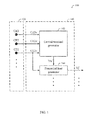
- FIG. 1 shows an ECG device according to an embodiment of the invention.
- FIG. 2 shows a schematic diagram illustrating how the electrodes of the electrode assembly of FIG. 1 may be attached to a patient's chest.
- FIG. 1 shows an ECG device according to an embodiment of the invention.
- the ECG device 100 includes an electrode assembly 120 and an ECG lead signal generating circuit 140.
- the electrode assembly 120 includes a plurality of electrodes to be attached to a patient's chest skin.
- the ECG lead signal generating circuit 140 generates at least one lead according to voltage levels of the electrodes.
- the ECG lead signal generating circuit 140 may pass the lead to a subsequent processor, which may then enable the waveform of the lead to be displayed or printed.
- the waveform may indicate the activities of the patient's heart.
- the electrode assembly 120 includes at least three cardio enclosure (CE) electrodes CE1, CE2, and CE3. These three electrodes are called CE electrodes because after being attached to the patient's chest, the three CE electrodes may form a triangle that substantially encloses the patient's heart (viewing from the patient's front).
- CE electrodes CE1, CE2, and CE3 one that's to the right of the heart may be referred to as a CR electrode, another that's to the left of the heart may be referred to as a CL electrode, and the other that's below the heart may be referred to as a CB electrode.
- the electrode assembly 120 may further contain some other optional electrodes not depicted in FIG. 1 .
- these optional electrodes may include a subset of a right leg drive electrode R, and precordial electrodes Ve1, Ve2, Ve3, Ve4, Ve5, and Ve6.
- the six precordial electrodes Ve1, Ve2, Ve3, Ve4, Ve5, and Ve6 are what conventionally used to generate six precordial leads V1, V2, V3, V4, V5, and V6 of a 12-lead ECG, respectively.
- the electrode assembly 120 may be implemented in a variety of ways.
- conductive wires may further be incorporated as a part of the electrode assembly 120.
- some of the connective wires may be tied in bundle style.
- wireless transmission may be adopted to eliminate the need of conductive wires and the electrode assembly 120 may employ wireless transmitting modules, for example, inside the electrodes.
- the ECG lead signal generating circuit 140 may perform signal processing on the electrical signals acquired by the electrodes in a remote place. It has to be emphasized that other various modifications made thereto without departing from the spirit and scope of this paragraph should all be perceived to be within the scope of the electrode assembly 120 of the invention.
- FIG. 2 shows a schematic diagram illustrating how the electrodes of the electrode assembly 120 may be attached to the patient's chest.
- the enclosed broken line 210 represents the heart in the patient's rib cage; the straight broken lines represent some imaginary anatomy lines; the small circles represent positions on the patient's chest where electrodes of the electrode assembly 120 may be attached to.
- position Ve1, CR1, or their vicinity is where the CR electrode (i.e. the right one of CE1, CE2, and CE3) may be attached to.
- Position CL1, CL2, CL3, or their vicinity is where the CL electrode (i.e. the left one of CE1, CE2, and CE3) may be attached to.
- Position Ve4, Ve5, Ve6, CB1, CB2, or their vicinity is where the CB electrode (i.e. the bottom one of CE1, CE2, and CE3) may be attached to.
- Positions Ve1, Ve2, Ve3, Ve4, Ve5, and Ve6 or their vicinity are where the optional precordial electrodes Ve1, Ve2, Ve3, Ve4, Ve5, and Ve6 may be attached to, respectively.
- the ECG lead signal generating circuit 140 includes a central terminal generator 142 and at least a precordial lead generator 144.
- the central terminal generator 142 uses three voltages CE1v, CE2v, and CE3v acquired by the three electrodes CE1, CE2, and CE3 respectively to generate a modified Wilson's central terminal Vw'.
- the central terminal generator 142 may average the three voltages CE1v CE2v, and CE3v to generate Vw'.
- the central terminal generator 142 may be an average circuit and Vw' may be equal to (CE1v + CE2v + CE3v) / 3.
- the CR electrode i.e. the right one of CE1, CE2, and CE3
- CR and Ve1 are merged as a merged electrode CRm.
- the merged electrode CRm may fulfill both the roles of CR and Ve1 in generating the relevant leads.
- the ECG lead signal generating circuit 140 of FIG. 1 may generate not only the modified Wilson's central terminal Vw' but also a modified precordial lead Vj', as shown in FIG. 1 .
- the electrode CE1 depicted in FIG. 1 is the CR electrode and is attached to position Ve1 depicted in FIG. 2
- Vj' may subtract Vw' from CE1v to generate Vj'.
- the precordial lead generator 144 may be a subtraction circuit and Vj' may be equal to CE1v - Vw'.
- the precordial electrode Ve1 for acquiring a precordial voltage Ve1v may be no longer needed since the function of Ve1v in deriving Vj' is realized by CE1v.
- the precordial electrode Ve1 cannot be omitted in deriving Vj' since by definition Vj' equals Ve1v - Vw'.
- Vj' may be (CE1v+ CE2v+ CE3v)/3.
- CE1v also functioning as Vo1v
- Vj' i.e. CE1v- Vw'
- CE1v- Vw' may be formulated as (CE1v- CE2v)/3 + (CE1v- CE3v)/3.
- the precordial lead generator may comprise two subtractors that derive the two terms (CE1v- CE2v) and (CE1v- CE3v), respectively and one adder to sum the aforementioned two terms.
- the central terminal generator 142 may be removed and the precordial lead generator 144 may generate Vj' according to CE1v, CE2v and CE3v, wherein CE1v, CE2v and CE3v are sufficient for generating Vj'.
- Vj1' the modified precordial lead, denoted as Vj1', generated according to CE1v, CE2v and CE3v but not according to Ve1v still bears similar characteristics as compared with the conventional modified precordial lead, denoted as Vj2', generated also according to Ve1v, in addition to CE1v, CE2v and CE3v.
- Vj1' may also help doctors make a correct diagnosis, just as Vj2'.
- Vj1' generated based on the proposed merged electrode concept may be as useful as Vj2' generated according to three cardio enclosure voltage and one precordial voltage for common practical applications.
- the CB electrode i.e. the bottom one of CE1, CE2, and CE3 is attached to one of positions Ve4, Ve5, and Ve6 or its vicinity, it may be said that CB and one of Ve4, Ve5, and Ve6 are merged as a merged electrode CBm.
- the merged electrode CBm may fulfill both the roles of CB and one of Vc4, Ve5, and Ve6 in generating the relevant leads.
- the ECG lead signal generating circuit 140 of FIG. 1 may generate not only the modified Wilson's central terminal Vw' but also a modified precordial lead V4', V5', or V6'. For example, if the electrode CE1 depicted in FIG.
- the precordial lead generator 144 of FIG. 1 may subtract Vw' from CE1v to generate V4', V5', or V6', which is labeled as Vj' in FIG. 1 .
- the precordial lead generator 144 of FIG. 1 may subtract Vw' from one of the merged electrodes' voltage (i.e. CE1v) to generate the modified precordial lead Vj', as also shown in FIG. 1 .
- the ECG lead signal generating circuit 140 of FIG. 1 may further include a second precordial lead generator that subtract Vw' from the voltage of the other of the merged electrodes (CE2v or CE3v) to generate another modified precordial lead Vk'.
- One of the variables j and k may be equal to 1 while the other may be equal to 4, 5, or 6. Note that for the sake of brevity, the second precordial lead generator is not drawn in FIG. 1 as it is easy to conceive how it can be fit into FIG. 1 .
- the central terminal generator 142 and the precordial lead generator 144 may be implemented by digital signal processors (DSP), application specific ICs (ASIC) or any form of electrical circuits.
- DSP digital signal processors
- ASIC application specific ICs
- the Vw' need not be sent to the precordial lead generator 144 through an electrically wired connection.
- the Vw' may be sent via wireless communication link so that the central terminal generator 142 and the precordial lead generator 144 may interact with each other remotely and wireless transceiver modules may be inside both of them.
- Each of positions Ve1, Ve4, Ve5, and Ve6 is a potential position for a merged electrode.
- position Ve1 is in a region of the fourth intercostal space at the right sternal border.
- Position Ve4 is in a region of the fifth intercostal space at the left mid-clavicular line.
- Position Ve5 is in a region of the fifth intercostal space at the left anterior axillary line.
- Position Ve6 is in a region of the fifth intercostal space at the left mid-axillary line.
- the ECG lead signal generating circuit 140 may further be configured to use voltages CRv, CLv, and CBv acquired respectively by the CR, CL, and CB electrodes to generate any of three modified limb leads I', II', and III', and any of three modified augmented limb leads aVR', aVL', and aVF'.
- the ECG lead signal generating circuit 140 may do so according to any of the following six equations.
- the ECG lead signal generating circuit 140 may be pure hardware. For example, it may include hardware average circuits and hardware subtraction circuits but no processors. Being pure hardware, the cost of the ECG lead signal generating circuit 140 may be relatively lower. In addition, the pure hardware does not generate leads through synthesis; instead, it generates leads directly based on the voltages it receives from the electrode assembly 120. This means that there is no synthesis parameter to be fine-tuned, making the ECG device 100 easier to use.
- the ECG device 100 may be able to generate up to 8+m modified leads using 3+m electrodes. These 8+m modified leads include 3 modified limb leads, 3 modified augmented limb leads, and 2+m modified precordial leads. If only one of the CR and CB electrodes is merged as a merged electrode CRm or CBm and the electrode assembly 120 further includes n other precordial electrodes (where n is equal to 0, 1, 2, 3, 4, or 5), the ECG device 100 may be able to generate 7+n modified leads using 3+n electrodes.
- 7+n modified leads include 3 modified limb leads, 3 modified augmented limb leads, and 1+n modified precordial leads.
- 3 electrodes LA, RA, and LL and pother precordial electrodes where p is equal to 0, 1, 2, 3, 4, 5, or 6
- a conventional ECG device may be able to generate only up to 6+p leads.
- 6+p leads include 3 limb leads, 3 augmented limb leads, and p precordial leads.
- the ECG device 100 of FIG. 1 is able to generate the same amount of leads with fewer electrodes. For example, if both the CR and CB electrodes are merged as merged electrodes CRm and CBm, it only takes 1 precordial electrode to generate 9 leads while the conventional ECG device requires 3 precordial electrodes. This means that the overall costs of the ECG device 100 may be relatively lower. In addition, because there are fewer electrodes to be attached to the patient's chest, the ECG device 100 is easier to use.
- the modified Wilson's central terminal Vw' is very similar to the Mason-Likar Wilson's central terminal Vw.
- substituting the latter with the former is a feasible approach.
- the modified precordial lead Vp' may still carry most of the information that the conventional precordial lead Vp would have carried, where p is equal to 1, 2, 3, 4, 5, or 6.
- the waveform of the modified precordial lead Vp' may also help a doctor make correct diagnosis.
- the modified limb leads I', II', and III', and the modified augmented limb leads aVR', aVL', and aVF' are very similar to the conventional limb leads I, II, and III, and the conventional augmented limb leads aVR, aVL, and aVF, respectively.
- substituting the latters with the formers is a feasible approach.
- the modified leads I', II', III', aVR', aVL', and aVF' may still carry most of the information that the conventional leads I, II, III, aVR, aVL, and aVF would have carried, respectively.
- the waveforms of the modified leads I, II, III, aVR, aVL, or aVF may also help a doctor make correct diagnosis.
Landscapes
- Health & Medical Sciences (AREA)
- Life Sciences & Earth Sciences (AREA)
- Heart & Thoracic Surgery (AREA)
- Medical Informatics (AREA)
- Biophysics (AREA)
- Pathology (AREA)
- Engineering & Computer Science (AREA)
- Biomedical Technology (AREA)
- Cardiology (AREA)
- Physics & Mathematics (AREA)
- Molecular Biology (AREA)
- Surgery (AREA)
- Animal Behavior & Ethology (AREA)
- General Health & Medical Sciences (AREA)
- Public Health (AREA)
- Veterinary Medicine (AREA)
- Electrotherapy Devices (AREA)
- Measurement And Recording Of Electrical Phenomena And Electrical Characteristics Of The Living Body (AREA)
Abstract
Description
- 1. Technical Field
- The invention relates generally to electrocardiography (ECG), and more particularly, to an ECG device, an ECG lead signal generating circuit, another ECG device, and related methods, and an ECG electrode assembly.
- 2. Related art
- An ECG device may generate electrical signals that indicate a person's heart activities. Each of the signals may be referred to as a lead or lead signal. By examining the waveforms of the leads with respect to time, a doctor may diagnose whether the patient has a heart disease.
- Nowadays, heart disease is becoming more prevalent and is causing health problems to countries around the world. One way to deal with this problem is to use the proposed ECG devices that are not only easier to use but also less expensive.
- An embodiment of the invention provides an ECG device. The ECG device comprises an electrode assembly and an ECG lead signal generating circuit. The electrode assembly comprises three cardio enclosure electrodes for acquiring three cardio enclosure voltages, respectively. The ECG lead signal generating circuit comprises a first precordial lead generator. The first precordial lead generator is configured to generate a first modified precordial lead according to the three cardio enclosure voltages, wherein the three cardio enclosure voltages are sufficient for generating the first modified precordial lead.
- Another embodiment of the invention provides an ECG signal processing method comprising the following steps. First, three cardio enclosure voltages are acquired from three cardio enclosure electrodes, respectively. Then, a first modified precordial lead is generated according to the three cardio enclosure voltages, wherein the three cardio enclosure voltages are sufficient for generating the first modified precordial lead.
- Still another embodiment of the invention provides an ECG lead signal generating circuit. The ECG lead signal generating circuit comprises a first precordial lead generator. The first precordial lead generator is configured to generate a first modified precordial lead according to three cardio enclosure voltages, wherein the three cardio enclosure voltages are sufficient for generating the first modified precordial lead.
- Another embodiment of the invention provides an ECG signal generating method comprising the following step. A first modified precordial lead is generated according to three cardio enclosure voltages, wherein the three cardio enclosure voltages are sufficient for generating the first modified precordial lead.
- Still another embodiment of the invention provides an ECG device. The ECG device comprises an electrode assembly and an ECG lead signal generating circuit. The electrode assembly comprises three cardio enclosure electrodes for acquiring three cardio enclosure voltages, respectively, and a precordial electrode for acquiring a precordial voltage. The ECG lead signal generating circuit comprises a first precordial lead generator. The first precordial lead generator is configured to generate a first modified precordial lead according to the three cardio enclosure voltages but not according to the precordial voltage.
- Another embodiment of the invention provides an ECG signal processing method comprising the following steps. First, three cardio enclosure voltages are acquired from three cardio enclosure electrodes, respectively, and a precordial voltage is acquired from a precordial electrode. Then, a first modified precordial lead is generated according to the three cardio enclosure voltages but not according to the precordial voltage.
- The other embodiment of the invention provides an ECG electrode assembly. The ECG electrode assembly comprises three cardio enclosure electrodes for acquiring three cardio enclosure voltages, wherein six modified leads and a modified precordial lead are able to be generated according to the three cardio enclosure voltages.
- Other features of the invention will be apparent from the accompanying drawings and from the detailed description which follows.
- The invention is fully illustrated by the subsequent detailed description and the accompanying drawings, in which like references indicate similar elements.
-
FIG. 1 shows an ECG device according to an embodiment of the invention. -
FIG. 2 shows a schematic diagram illustrating how the electrodes of the electrode assembly ofFIG. 1 may be attached to a patient's chest. -
FIG. 1 shows an ECG device according to an embodiment of the invention. TheECG device 100 includes anelectrode assembly 120 and an ECG leadsignal generating circuit 140. Theelectrode assembly 120 includes a plurality of electrodes to be attached to a patient's chest skin. The ECG leadsignal generating circuit 140 generates at least one lead according to voltage levels of the electrodes. The ECG leadsignal generating circuit 140 may pass the lead to a subsequent processor, which may then enable the waveform of the lead to be displayed or printed. The waveform may indicate the activities of the patient's heart. - In the embodiment shown in
FIG. 1 , theelectrode assembly 120 includes at least three cardio enclosure (CE) electrodes CE1, CE2, and CE3. These three electrodes are called CE electrodes because after being attached to the patient's chest, the three CE electrodes may form a triangle that substantially encloses the patient's heart (viewing from the patient's front). Among the three CE electrodes CE1, CE2, and CE3, one that's to the right of the heart may be referred to as a CR electrode, another that's to the left of the heart may be referred to as a CL electrode, and the other that's below the heart may be referred to as a CB electrode. - In addition to the electrodes CE1, CE2, and CE3, the
electrode assembly 120 may further contain some other optional electrodes not depicted inFIG. 1 . For example, these optional electrodes may include a subset of a right leg drive electrode R, and precordial electrodes Ve1, Ve2, Ve3, Ve4, Ve5, and Ve6. The six precordial electrodes Ve1, Ve2, Ve3, Ve4, Ve5, and Ve6 are what conventionally used to generate six precordial leads V1, V2, V3, V4, V5, and V6 of a 12-lead ECG, respectively. - In practice, the
electrode assembly 120 may be implemented in a variety of ways. For transmitting electrical signals acquired by the electrodes to the ECG leadsignal generating circuit 140, conductive wires may further be incorporated as a part of theelectrode assembly 120. To make the wire connections in better order, as an example, some of the connective wires may be tied in bundle style. However, in some situations wireless transmission may be adopted to eliminate the need of conductive wires and theelectrode assembly 120 may employ wireless transmitting modules, for example, inside the electrodes. In this way, the ECG leadsignal generating circuit 140 may perform signal processing on the electrical signals acquired by the electrodes in a remote place. It has to be emphasized that other various modifications made thereto without departing from the spirit and scope of this paragraph should all be perceived to be within the scope of theelectrode assembly 120 of the invention. -
FIG. 2 shows a schematic diagram illustrating how the electrodes of theelectrode assembly 120 may be attached to the patient's chest. InFIG. 2 , the enclosed broken line 210 represents the heart in the patient's rib cage; the straight broken lines represent some imaginary anatomy lines; the small circles represent positions on the patient's chest where electrodes of theelectrode assembly 120 may be attached to. - In
FIG. 2 , position Ve1, CR1, or their vicinity is where the CR electrode (i.e. the right one of CE1, CE2, and CE3) may be attached to. Position CL1, CL2, CL3, or their vicinity is where the CL electrode (i.e. the left one of CE1, CE2, and CE3) may be attached to. Position Ve4, Ve5, Ve6, CB1, CB2, or their vicinity is where the CB electrode (i.e. the bottom one of CE1, CE2, and CE3) may be attached to. Positions Ve1, Ve2, Ve3, Ve4, Ve5, and Ve6 or their vicinity are where the optional precordial electrodes Ve1, Ve2, Ve3, Ve4, Ve5, and Ve6 may be attached to, respectively. - Please refer back to
FIG. 1 . The ECG leadsignal generating circuit 140 includes acentral terminal generator 142 and at least aprecordial lead generator 144. Instead of using three voltages provided by a right arm (RA) electrode, a left arm (LA) electrode, and a left leg (LL) electrode to generate a Wilson's central terminal Vw in a conventional way, thecentral terminal generator 142 uses three voltages CE1v, CE2v, and CE3v acquired by the three electrodes CE1, CE2, and CE3 respectively to generate a modified Wilson's central terminal Vw'. For example, thecentral terminal generator 142 may average the three voltages CE1v CE2v, and CE3v to generate Vw'. In other words, thecentral terminal generator 142 may be an average circuit and Vw' may be equal to (CE1v + CE2v + CE3v) / 3. - If the CR electrode (i.e. the right one of CE1, CE2, and CE3) is attached to position Ve1 or its vicinity, it may be said that CR and Ve1 are merged as a merged electrode CRm. The merged electrode CRm may fulfill both the roles of CR and Ve1 in generating the relevant leads. Partly based on the voltage level of this merged electrode CRm, the ECG lead
signal generating circuit 140 ofFIG. 1 may generate not only the modified Wilson's central terminal Vw' but also a modified precordial lead Vj', as shown inFIG. 1 . For example, if the electrode CE1 depicted inFIG. 1 is the CR electrode and is attached to position Ve1 depicted inFIG. 2 , theprecordial lead generator 144 ofFIG. 1 may subtract Vw' from CE1v to generate Vj'. In other words, theprecordial lead generator 144 may be a subtraction circuit and Vj' may be equal to CE1v - Vw'. In this way, the precordial electrode Ve1 for acquiring a precordial voltage Ve1v may be no longer needed since the function of Ve1v in deriving Vj' is realized by CE1v. Without the merging electrode idea presented in this paragraph, the precordial electrode Ve1 cannot be omitted in deriving Vj' since by definition Vj' equals Ve1v - Vw'. - It has to be pointed out that, through some mathematical manipulation, there are other approaches to generate Vj'. As an example, consider Vw' to be (CE1v+ CE2v+ CE3v)/3. With CE1v also functioning as Vo1v, Vj' (i.e. CE1v- Vw') may be formulated as (CE1v- CE2v)/3 + (CE1v- CE3v)/3. As an example for generating Vj' without the
central terminal generator 142, the precordial lead generator may comprise two subtractors that derive the two terms (CE1v- CE2v) and (CE1v- CE3v), respectively and one adder to sum the aforementioned two terms. Of course, one can easily come up with different formulations for deriving Vj'; however, any of such variants not departing from the spirit of the disclosure above shall be regarded to fall within the scope of the invention. Also, the formulation provided in this example may be applied to other merged electrode cases described below and will be omitted later for the sake of brevity. - Therefore, according to previous two paragraphs, it can be said that the
central terminal generator 142 may be removed and theprecordial lead generator 144 may generate Vj' according to CE1v, CE2v and CE3v, wherein CE1v, CE2v and CE3v are sufficient for generating Vj'. Note that using the word sufficient means the modified precordial lead, denoted as Vj1', generated according to CE1v, CE2v and CE3v but not according to Ve1v still bears similar characteristics as compared with the conventional modified precordial lead, denoted as Vj2', generated also according to Ve1v, in addition to CE1v, CE2v and CE3v. To be more specific, according to experimental results, it can be shown the morphology and level of Vj1' and Vj2' are similar. Secondly, Vj1' may also help doctors make a correct diagnosis, just as Vj2'. This suggests Vj1' generated based on the proposed merged electrode concept may be as useful as Vj2' generated according to three cardio enclosure voltage and one precordial voltage for common practical applications. - If the CB electrode (i.e. the bottom one of CE1, CE2, and CE3) is attached to one of positions Ve4, Ve5, and Ve6 or its vicinity, it may be said that CB and one of Ve4, Ve5, and Ve6 are merged as a merged electrode CBm. The merged electrode CBm may fulfill both the roles of CB and one of Vc4, Ve5, and Ve6 in generating the relevant leads. Partly based on the voltage level of this merged electrode, the ECG lead
signal generating circuit 140 ofFIG. 1 may generate not only the modified Wilson's central terminal Vw' but also a modified precordial lead V4', V5', or V6'. For example, if the electrode CE1 depicted inFIG. 1 is the CB electrode and is attached to position Ve4, Ve5, or Ve6 depicted inFIG. 2 , theprecordial lead generator 144 ofFIG. 1 may subtract Vw' from CE1v to generate V4', V5', or V6', which is labeled as Vj' inFIG. 1 . - If both the CR and CB electrodes are merged respectively as merged electrodes CRm and CBm, the
precordial lead generator 144 ofFIG. 1 may subtract Vw' from one of the merged electrodes' voltage (i.e. CE1v) to generate the modified precordial lead Vj', as also shown inFIG. 1 . In addition, the ECG leadsignal generating circuit 140 ofFIG. 1 may further include a second precordial lead generator that subtract Vw' from the voltage of the other of the merged electrodes (CE2v or CE3v) to generate another modified precordial lead Vk'. One of the variables j and k may be equal to 1 while the other may be equal to 4, 5, or 6. Note that for the sake of brevity, the second precordial lead generator is not drawn inFIG. 1 as it is easy to conceive how it can be fit intoFIG. 1 . - In practice, there are several ways to implement the ECG lead
signal generating circuit 140. For instance, thecentral terminal generator 142 and theprecordial lead generator 144 may be implemented by digital signal processors (DSP), application specific ICs (ASIC) or any form of electrical circuits. Besides, the Vw' need not be sent to theprecordial lead generator 144 through an electrically wired connection. For instance, the Vw' may be sent via wireless communication link so that thecentral terminal generator 142 and theprecordial lead generator 144 may interact with each other remotely and wireless transceiver modules may be inside both of them. - Please refer to
FIG. 2 . Each of positions Ve1, Ve4, Ve5, and Ve6 is a potential position for a merged electrode. For example, position Ve1 is in a region of the fourth intercostal space at the right sternal border. Position Ve4 is in a region of the fifth intercostal space at the left mid-clavicular line. Position Ve5 is in a region of the fifth intercostal space at the left anterior axillary line. Position Ve6 is in a region of the fifth intercostal space at the left mid-axillary line. - Please refer back to
FIG. 1 . If theelectrode assembly 120 has a precordial electrode Vei (where i is equal to 1, 2, 3, 4, 5, or 6) that's not merged with any of the three CE electrodes, the ECG leadsignal generating circuit 140 may further include a lead signal generator that generate a modified precordial lead Vi' based on precordial voltage Veiv acquired by precordial electrode Vei and the modified Wilson's central terminal Vw'. Specifically, this lead signal generator may subtract Vw' from Veiv to generate Vi'. In other words, Vi' = Veiv -Vw'. With Vi' and the modified precordial lead Vj' depicted inFIG. 1 , the ECG leadsignal generating circuit 140 may generate up to six modified precordial leads. - In addition to at least one modified precordial lead, the ECG lead
signal generating circuit 140 may further be configured to use voltages CRv, CLv, and CBv acquired respectively by the CR, CL, and CB electrodes to generate any of three modified limb leads I', II', and III', and any of three modified augmented limb leads aVR', aVL', and aVF'. Specifically, the ECG leadsignal generating circuit 140 may do so according to any of the following six equations.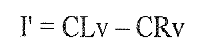



- The ECG lead
signal generating circuit 140 may be pure hardware. For example, it may include hardware average circuits and hardware subtraction circuits but no processors. Being pure hardware, the cost of the ECG leadsignal generating circuit 140 may be relatively lower. In addition, the pure hardware does not generate leads through synthesis; instead, it generates leads directly based on the voltages it receives from theelectrode assembly 120. This means that there is no synthesis parameter to be fine-tuned, making theECG device 100 easier to use. - If both the CR and CB electrodes are merged respectively as merged electrodes CRm and CBm and the
electrode assembly 120 further includes m other precordial electrodes (where m is equal to 0, 1, 2, 3, or 4), theECG device 100 may be able to generate up to 8+m modified leads using 3+m electrodes. These 8+m modified leads include 3 modified limb leads, 3 modified augmented limb leads, and 2+m modified precordial leads. If only one of the CR and CB electrodes is merged as a merged electrode CRm or CBm and theelectrode assembly 120 further includes n other precordial electrodes (where n is equal to 0, 1, 2, 3, 4, or 5), theECG device 100 may be able to generate 7+n modified leads using 3+n electrodes. These 7+n modified leads include 3 modified limb leads, 3 modified augmented limb leads, and 1+n modified precordial leads. In contrast, with 3 electrodes LA, RA, and LL and pother precordial electrodes (where p is equal to 0, 1, 2, 3, 4, 5, or 6), a conventional ECG device may be able to generate only up to 6+p leads. These 6+p leads include 3 limb leads, 3 augmented limb leads, and p precordial leads. - Apparently, because at least one of the CR and CB electrodes is merged as a merged electrode, the
ECG device 100 ofFIG. 1 is able to generate the same amount of leads with fewer electrodes. For example, if both the CR and CB electrodes are merged as merged electrodes CRm and CBm, it only takes 1 precordial electrode to generate 9 leads while the conventional ECG device requires 3 precordial electrodes. This means that the overall costs of theECG device 100 may be relatively lower. In addition, because there are fewer electrodes to be attached to the patient's chest, theECG device 100 is easier to use. - After conducting several experiments, it has been shown that the modified Wilson's central terminal Vw' is very similar to the Mason-Likar Wilson's central terminal Vw. As a result, substituting the latter with the former is a feasible approach. Even with the substitution, the modified precordial lead Vp' may still carry most of the information that the conventional precordial lead Vp would have carried, where p is equal to 1, 2, 3, 4, 5, or 6. In other words, just like the waveform of the conventional precordial lead Vp, the waveform of the modified precordial lead Vp' may also help a doctor make correct diagnosis.
- In addition, the experiments have also shown that the modified limb leads I', II', and III', and the modified augmented limb leads aVR', aVL', and aVF' are very similar to the conventional limb leads I, II, and III, and the conventional augmented limb leads aVR, aVL, and aVF, respectively. As a result, substituting the latters with the formers is a feasible approach. Even with the substitution, the modified leads I', II', III', aVR', aVL', and aVF' may still carry most of the information that the conventional leads I, II, III, aVR, aVL, and aVF would have carried, respectively. In other words, just like the waveforms of the conventional leads I, II, III, aVR, aVL, and aVF, the waveforms of the modified leads I, II, III, aVR, aVL, or aVF may also help a doctor make correct diagnosis.
- In the foregoing detailed description, the invention has been described with reference to specific exemplary embodiments thereof. It will be evident that various modifications may be made thereto without departing from the spirit and scope of the invention as set forth in the following claims. The detailed description and drawings are, accordingly, to be regarded in an illustrative sense rather than a restrictive sense.
Claims (22)
- An ECG device, comprising:an electrode assembly, comprising three cardio enclosure electrodes for acquiring three cardio enclosure voltages, respectively; andan ECG lead signal generating circuit, comprising:a first precordial lead generator, coupled to the electrode assembly, configured to generate a first modified precordial lead according to the three cardio enclosure voltages, wherein the three cardio enclosure voltages are sufficient for generating the first modified precordial lead.
- The ECG device of claim 1, wherein the ECG lead signal generating circuit further comprises a central terminal generator, configured to average the three cardio enclosure voltages to generate a modified Wilson's central terminal; and the first precordial lead generator is configured to subtract the modified Wilson's central terminal from a first one of the three cardio enclosure voltages to generate the first modified precordial lead.
- The ECG device of claim 1, wherein the electrode assembly further comprises n precordial electrodes for acquiring n precordial voltages, where n is equal to 0, 1, 2, 3, 4, or 5, and the ECG lead signal generating circuit is configured to generate 7+n modified leads according to the 3 cardio enclosure voltages and the n precordial voltages.
- An ECG signal processing method, comprising:acquiring three cardio enclosure voltages from three cardio enclosure electrodes, respectively; andgenerating a first modified precordial lead according to the three cardio enclosure voltages, wherein the three cardio enclosure voltages are sufficient for generating the first modified precordial lead.
- The ECG signal processing method of claim 4, further comprising generating a modified Wilson's central terminal by averaging the three cardio enclosure voltages; and
the first modified precordial lead is generated by subtracting the modified Wilson's central terminal from a first one of the three cardio enclosure voltages. - The ECG signal processing method of claim 4, wherein:a first one of the three cardio enclosure electrodes that acquires the first one of the three cardio enclosure voltages is attached to a region of the fourth intercostal space at the right sternal border.
- The ECG signal processing method of claim 4, wherein:a first one of the three cardio enclosure electrodes that acquires the first one of the three cardio enclosure voltages is attached to one of a first region of the fifth intercostal space at the left mid-clavicular line, a second region of the fifth intercostal space at the left anterior axillary line, and a third region of the fifth intercostal space at the left mid-axillary line.
- The ECG signal processing method of claim 4, further comprising acquiring n precordial voltages from n precordial electrodes, where n is equal to 0, 1, 2, 3, 4, or 5, and 7+n modified leads are generated according to the 3 cardio enclosure voltages and the n precordial voltages.
- An ECG lead signal generating circuit, comprising:a first precordial lead generator, configured to generate a first modified precordial lead according to three cardio enclosure voltages, wherein the three cardio enclosure voltages are sufficient for generating the first modified precordial lead.
- The ECG lead signal generating circuit of claim 9, further comprises a central terminal generator, configured to average the three cardio enclosure voltages to generate a modified Wilson's central terminal; and
the first precordial lead generator is configured to subtract the modified Wilson's central terminal from a first one of the three cardio enclosure voltages to generate the first modified precordial lead. - The ECG lead signal generating circuit of claim 9, wherein the ECG lead signal generating circuit is configured to receive the 3 cardio enclosure voltages and n precordial voltages to generate 7+n modified leads accordingly, where n is equal to 0, 1, 2, 3, 4, or 5.
- An ECG signal generating method, comprising:generating a first modified precordial lead according to three cardio enclosure voltages, wherein the three cardio enclosure voltages are sufficient for generating the first modified precordial lead.
- The ECG signal generating method of claim 12, further comprises generating a modified Wilson's central terminal by averaging the three cardio enclosure voltages; and
the first modified precordial lead is generated by subtracting the modified Wilson's central terminal from a first one of the three cardio enclosure voltages. - The ECG signal generating method of claim 12, further comprising receiving n precordial voltages, where n is equal to 0, 1, 2, 3, 4, or 5, and 7+n modified leads are generated according to the 3 cardio enclosure voltages and the n precordial voltages.
- An ECG device, comprising:an electrode assembly, comprising three cardio enclosure electrodes for acquiring three cardio enclosure voltages, respectively, and a precordial electrode for acquiring a precordial voltage; andan ECG lead signal generating circuit, comprising:a first precordial lead generator, coupled to the electrode assembly, configured to generate a first modified precordial lead according to the three cardio enclosure voltages but not according to the precordial voltage.
- The ECG device of claim 15, wherein the ECG lead signal generating circuit further comprises a central terminal generator, configured to average the three cardio enclosure voltages to generate a modified Wilson's central terminal; and the first precordial lead generator is configured to subtract the modified Wilson's central terminal from a first one of the three cardio enclosure voltages to generate the first modified precordial lead.
- The ECG device of claim 15, wherein the electrode assembly further comprises n precordial electrodes for acquiring n precordial voltages, where n is equal to 0, 1, 2, 3, 4, or 5, and the ECG lead signal generating circuit is configured to generate 7+n modified leads according to the 3 cardio enclosure voltages and the n precordial voltages.
- An ECG signal processing method, comprising:acquiring three cardio enclosure voltages from three cardio enclosure electrodes, respectively, and acquiring a precordial voltage from a precordial electrode; andgenerating a first modified precordial lead according to the three cardio enclosure voltages but not according to the precordial voltage.
- The ECG signal processing method of claim 18, further comprises generating a modified Wilson's central terminal by averaging the three cardio enclosure voltages; and
the first modified precordial lead is generated by subtracting the modified Wilson's central terminal from a first one of the three cardio enclosure voltages. - The ECG signal processing method of claim 18, further comprising acquiring n precordial voltages from n precordial electrodes, where n is equal to 0, 1, 2, 3, 4, or 5, and 7+n modified leads are generated according to the 3 cardio enclosure voltages and the n precordial voltages.
- An ECG electrode assembly, comprising:three cardio enclosure electrodes for acquiring three cardio enclosure voltages, wherein six modified leads and a modified precordial lead are able to be generated according to the three cardio enclosure voltages.
- The ECG electrode assembly of claim 21, further comprising n precordial electrodes for acquiring n precordial voltages, where n is equal to 0, 1, 2, 3, 4, or 5, and 7+n modified leads are able to be generated according to the 3 cardio enclosure voltages and the n precordial voltages.
Applications Claiming Priority (1)
| Application Number | Priority Date | Filing Date | Title |
|---|---|---|---|
| US14/048,057 US9167981B2 (en) | 2013-10-08 | 2013-10-08 | ECG device, ECG lead signal generating circuit, and related method |
Publications (1)
| Publication Number | Publication Date |
|---|---|
| EP2859843A1 true EP2859843A1 (en) | 2015-04-15 |
Family
ID=49518654
Family Applications (1)
| Application Number | Title | Priority Date | Filing Date |
|---|---|---|---|
| EP13188424.9A Withdrawn EP2859843A1 (en) | 2013-10-08 | 2013-10-14 | ECG device, ECG lead signal generating circuit, and related method |
Country Status (3)
| Country | Link |
|---|---|
| US (1) | US9167981B2 (en) |
| EP (1) | EP2859843A1 (en) |
| CN (1) | CN104510462B (en) |
Cited By (1)
| Publication number | Priority date | Publication date | Assignee | Title |
|---|---|---|---|---|
| EP3391814A1 (en) * | 2017-04-19 | 2018-10-24 | Siemens Healthcare GmbH | Reference methodology for ecg vector reconstruction |
Families Citing this family (3)
| Publication number | Priority date | Publication date | Assignee | Title |
|---|---|---|---|---|
| CN106388808B (en) * | 2015-06-26 | 2021-05-25 | 席剑 | Novel multichannel electrocardiogram acquisition scheme |
| JP7767288B2 (en) | 2019-12-23 | 2025-11-11 | アリメトリー リミテッド | Electrode Patch and Connection System |
| CN117643472A (en) * | 2022-09-05 | 2024-03-05 | 荣耀终端有限公司 | Multi-lead electrocardiograph detection method and electronic equipment |
Citations (6)
| Publication number | Priority date | Publication date | Assignee | Title |
|---|---|---|---|---|
| US4608987A (en) * | 1982-12-03 | 1986-09-02 | Physioventures, Inc. | Apparatus for transmitting ECG data |
| US20030233129A1 (en) * | 2002-06-11 | 2003-12-18 | Matos Jeffrey A. | System for cardiac resuscitation |
| US7266405B1 (en) * | 1999-08-23 | 2007-09-04 | Shl Telemedicine International Ltd. | Compact electrode assembly for a portable ECG signaling device |
| US20080064972A1 (en) * | 2004-10-25 | 2008-03-13 | Kwek Alfred T C | System, Method and Apparatus for Detecting a Cardiac Event |
| US20120010515A1 (en) * | 2007-08-07 | 2012-01-12 | Koninklijke Philips Electronics N.V. | Automated Identification of Culprit Coronary Artery |
| US20120165633A1 (en) * | 2010-12-28 | 2012-06-28 | Mohammad Khair | Leadless wireless ecg measurement system and method for measuring of bio-potential electrical activity of the heart |
Family Cites Families (5)
| Publication number | Priority date | Publication date | Assignee | Title |
|---|---|---|---|---|
| US5938597A (en) * | 1995-05-04 | 1999-08-17 | Stratbucker; Robert A. | Electrocardiograph bioelectric interface system and method of use |
| US5678545A (en) * | 1995-05-04 | 1997-10-21 | Stratbucker; Robert A. | Anisotropic adhesive multiple electrode system, and method of use |
| CN1124823C (en) * | 1995-07-28 | 2003-10-22 | 北京新兴生物医学工程研究发展中心 | Standard cardioelectric lead meauring method without wilson network |
| CN2436099Y (en) * | 2000-07-25 | 2001-06-27 | 安刚 | Cardioelectric detecting, monitoring remote transmitter |
| US20030045804A1 (en) * | 2001-08-31 | 2003-03-06 | G.E. Medical Systems Information Technologies | Method and apparatus for generating electrocardiogram precordial leads using a precordial central terminal |
-
2013
- 2013-10-08 US US14/048,057 patent/US9167981B2/en active Active
- 2013-10-14 EP EP13188424.9A patent/EP2859843A1/en not_active Withdrawn
-
2014
- 2014-03-06 CN CN201410081708.4A patent/CN104510462B/en active Active
Patent Citations (6)
| Publication number | Priority date | Publication date | Assignee | Title |
|---|---|---|---|---|
| US4608987A (en) * | 1982-12-03 | 1986-09-02 | Physioventures, Inc. | Apparatus for transmitting ECG data |
| US7266405B1 (en) * | 1999-08-23 | 2007-09-04 | Shl Telemedicine International Ltd. | Compact electrode assembly for a portable ECG signaling device |
| US20030233129A1 (en) * | 2002-06-11 | 2003-12-18 | Matos Jeffrey A. | System for cardiac resuscitation |
| US20080064972A1 (en) * | 2004-10-25 | 2008-03-13 | Kwek Alfred T C | System, Method and Apparatus for Detecting a Cardiac Event |
| US20120010515A1 (en) * | 2007-08-07 | 2012-01-12 | Koninklijke Philips Electronics N.V. | Automated Identification of Culprit Coronary Artery |
| US20120165633A1 (en) * | 2010-12-28 | 2012-06-28 | Mohammad Khair | Leadless wireless ecg measurement system and method for measuring of bio-potential electrical activity of the heart |
Cited By (1)
| Publication number | Priority date | Publication date | Assignee | Title |
|---|---|---|---|---|
| EP3391814A1 (en) * | 2017-04-19 | 2018-10-24 | Siemens Healthcare GmbH | Reference methodology for ecg vector reconstruction |
Also Published As
| Publication number | Publication date |
|---|---|
| CN104510462A (en) | 2015-04-15 |
| US9167981B2 (en) | 2015-10-27 |
| US20150099957A1 (en) | 2015-04-09 |
| CN104510462B (en) | 2017-05-17 |
Similar Documents
| Publication | Publication Date | Title |
|---|---|---|
| US6052615A (en) | Method and apparatus for sensing and analyzing electrical activity of the human heart using a four electrode arrangement | |
| US9622674B2 (en) | Method and system for generating twelve-lead electrocardiogram signals using three differential voltages | |
| Baquero et al. | Surface 12 lead electrocardiogram recordings using smart phone technology | |
| US9167981B2 (en) | ECG device, ECG lead signal generating circuit, and related method | |
| Drew | Pitfalls and artifacts in electrocardiography | |
| JP2003529407A (en) | Method and apparatus for reconstructing Frank leads from derived chest leads | |
| CN115886831B (en) | Multi-lead ECG detection method and electronic equipment | |
| US10085662B2 (en) | Device and method for digital-to-analog transformations and reconstructions of multi-channel electrocardiograms | |
| Crawford et al. | Practical aspects of ECG recording | |
| US20240057918A1 (en) | Electrocardiogram Apparatus | |
| Gargiulo et al. | Towards true unipolar ECG recording without the Wilson central terminal (preliminary results) | |
| Salinet et al. | A 64-lead body surface potential mapping system | |
| CN104545882B (en) | Electrocardiogram measuring device and synthesis electrocardio drawing generating method | |
| US20240407724A1 (en) | Medical diagnostic garment | |
| Hazrati et al. | Wireless brain signal recordings based on capacitive electrodes | |
| Toinga et al. | Development of a didactic platform for teaching the Einthoven's Triangle | |
| de Oliveira et al. | Portable electrocardiograph based on the integrated circuit ADS1294 using an android application as interface | |
| Rjoob et al. | Machine learning improves the detection of misplaced v1 and v2 electrodes during 12-lead electrocardiogram acquisition | |
| EP4287949A1 (en) | Screen printed electrodes for an electrocardiogram article | |
| Chiang et al. | A new 3-D display method for 12-lead ECG | |
| Mond et al. | Twisted leads: the footprints of malpositioned electrocardiographic leads | |
| Cao et al. | Design and evaluation of a novel wireless three-pad ECG system for generating conventional 12-lead signals | |
| CN208355461U (en) | electrocardiogram capturing device | |
| JP2020049180A (en) | Electrocardiographic measuring apparatus | |
| De Oliveira et al. | Portable electrocardiograph through android application |
Legal Events
| Date | Code | Title | Description |
|---|---|---|---|
| PUAI | Public reference made under article 153(3) epc to a published international application that has entered the european phase |
Free format text: ORIGINAL CODE: 0009012 |
|
| 17P | Request for examination filed |
Effective date: 20131014 |
|
| AK | Designated contracting states |
Kind code of ref document: A1 Designated state(s): AL AT BE BG CH CY CZ DE DK EE ES FI FR GB GR HR HU IE IS IT LI LT LU LV MC MK MT NL NO PL PT RO RS SE SI SK SM TR |
|
| AX | Request for extension of the european patent |
Extension state: BA ME |
|
| R17P | Request for examination filed (corrected) |
Effective date: 20150515 |
|
| RBV | Designated contracting states (corrected) |
Designated state(s): AL AT BE BG CH CY CZ DE DK EE ES FI FR GB GR HR HU IE IS IT LI LT LU LV MC MK MT NL NO PL PT RO RS SE SI SK SM TR |
|
| 17Q | First examination report despatched |
Effective date: 20151016 |
|
| STAA | Information on the status of an ep patent application or granted ep patent |
Free format text: STATUS: THE APPLICATION IS DEEMED TO BE WITHDRAWN |
|
| 18D | Application deemed to be withdrawn |
Effective date: 20181206 |