EP2858427A1 - Wireless communication system, wireless station, base station and communication method - Google Patents
Wireless communication system, wireless station, base station and communication method Download PDFInfo
- Publication number
- EP2858427A1 EP2858427A1 EP12877677.0A EP12877677A EP2858427A1 EP 2858427 A1 EP2858427 A1 EP 2858427A1 EP 12877677 A EP12877677 A EP 12877677A EP 2858427 A1 EP2858427 A1 EP 2858427A1
- Authority
- EP
- European Patent Office
- Prior art keywords
- wireless
- base station
- transition
- station
- control signal
- Prior art date
- Legal status (The legal status is an assumption and is not a legal conclusion. Google has not performed a legal analysis and makes no representation as to the accuracy of the status listed.)
- Ceased
Links
Images





Classifications
-
- H—ELECTRICITY
- H04—ELECTRIC COMMUNICATION TECHNIQUE
- H04W—WIRELESS COMMUNICATION NETWORKS
- H04W52/00—Power management, e.g. Transmission Power Control [TPC] or power classes
- H04W52/02—Power saving arrangements
- H04W52/0209—Power saving arrangements in terminal devices
- H04W52/0212—Power saving arrangements in terminal devices managed by the network, e.g. network or access point is leader and terminal is follower
- H04W52/0216—Power saving arrangements in terminal devices managed by the network, e.g. network or access point is leader and terminal is follower using a pre-established activity schedule, e.g. traffic indication frame
-
- H—ELECTRICITY
- H04—ELECTRIC COMMUNICATION TECHNIQUE
- H04W—WIRELESS COMMUNICATION NETWORKS
- H04W12/00—Security arrangements; Authentication; Protecting privacy or anonymity
- H04W12/10—Integrity
- H04W12/106—Packet or message integrity
-
- H—ELECTRICITY
- H04—ELECTRIC COMMUNICATION TECHNIQUE
- H04W—WIRELESS COMMUNICATION NETWORKS
- H04W72/00—Local resource management
- H04W72/20—Control channels or signalling for resource management
- H04W72/21—Control channels or signalling for resource management in the uplink direction of a wireless link, i.e. towards the network
-
- H—ELECTRICITY
- H04—ELECTRIC COMMUNICATION TECHNIQUE
- H04W—WIRELESS COMMUNICATION NETWORKS
- H04W72/00—Local resource management
- H04W72/20—Control channels or signalling for resource management
- H04W72/23—Control channels or signalling for resource management in the downlink direction of a wireless link, i.e. towards a terminal
-
- H—ELECTRICITY
- H04—ELECTRIC COMMUNICATION TECHNIQUE
- H04W—WIRELESS COMMUNICATION NETWORKS
- H04W76/00—Connection management
- H04W76/20—Manipulation of established connections
- H04W76/27—Transitions between radio resource control [RRC] states
-
- H—ELECTRICITY
- H04—ELECTRIC COMMUNICATION TECHNIQUE
- H04W—WIRELESS COMMUNICATION NETWORKS
- H04W88/00—Devices specially adapted for wireless communication networks, e.g. terminals, base stations or access point devices
- H04W88/08—Access point devices
-
- Y—GENERAL TAGGING OF NEW TECHNOLOGICAL DEVELOPMENTS; GENERAL TAGGING OF CROSS-SECTIONAL TECHNOLOGIES SPANNING OVER SEVERAL SECTIONS OF THE IPC; TECHNICAL SUBJECTS COVERED BY FORMER USPC CROSS-REFERENCE ART COLLECTIONS [XRACs] AND DIGESTS
- Y02—TECHNOLOGIES OR APPLICATIONS FOR MITIGATION OR ADAPTATION AGAINST CLIMATE CHANGE
- Y02D—CLIMATE CHANGE MITIGATION TECHNOLOGIES IN INFORMATION AND COMMUNICATION TECHNOLOGIES [ICT], I.E. INFORMATION AND COMMUNICATION TECHNOLOGIES AIMING AT THE REDUCTION OF THEIR OWN ENERGY USE
- Y02D30/00—Reducing energy consumption in communication networks
- Y02D30/70—Reducing energy consumption in communication networks in wireless communication networks
Definitions
- processing is performed at the radio resource control (RRC) layer and includes the configuration, reconfiguration, and release of connections between wireless stations and base stations (for example, refer to Patent Documents 1 and 2 below).
- RRC radio resource control
- an RRC connected mode (RRC Connected) and a RRC idle mode (RRC Idle) are specified as states of the RRC layer (for example, refer to Non-Patent Literature 1 below).
- the RRC connected mode for example, is a state in which data communication can be implemented between a wireless station and a base station.
- the RRC idle mode for example, is a state in which data communication between a wireless station and a base station is not possible.
- an object of the present invention is to provide a wireless communications system, a wireless station, a base station, and a communications method that can facilitate communication efficiency.
- a wireless communications system a wireless station, a base station, and a communications method are proposed that, after receiving a first control signal that includes classifying information, configure by a second control signal, transition of a communication mode and releases by a third control signal, the transition of the communication mode, and perform transition of a communication mode by communication mode configured by the second control signal, and release by the third control signal, the transition of the communication mode.
- the wireless station 101 and the base station 102 transition to the first mode (step S104).
- the wireless station 101 and the base station 102 perform data communication with each other (step S105).
- the wireless station 101 and the base station 102 transition to a second mode (step S106).
- the second mode is a non-communication mode in which data communication is not possible, e.g., the idle mode (idle).
- the wireless station 101 and the base station 102 transition to the first mode in which data communication is possible (step S107).
- the wireless station 101 and the base station 102 perform data communication with each other (step S108).
- the wireless station 101 and the base station 102 transition to the second mode in which data communication is not possible (step S109).
- the wireless station 101 and the base station 102 execute steps S107 to S109, each time the transition timing configured at step S103 arrives.
- notification of the wireless parameter used in the data communication at step S108 does not have to be given to the wireless station 101 by the base station 102, thereby enabling reduction of the control signal overhead accompanying state transition. Further, since random access does not have to be performed for the data communication at step S108, reduction of the control signal overhead accompanying state transition is possible. Therefore, communication efficiency can be facilitated.
- the data communication at steps S105, S108 may be the transmission of uplink data from the wireless station 101 to the base station 102, or the transmission of downlink data from the base station 102 to the wireless station 101. Further, the data communication at steps S105, S108 may be both the transmission of uplink data from the wireless station 101 to the base station 102 and the transmission of downlink data from the base station 102 to the wireless station 101.
- the wireless station 101 transmits a random access preamble to the base station 102 (step S201).
- the base station 102 determines based on the reception timing of the random access preamble, the transmission timing of the uplink signal from the wireless station 101.
- the determination of the transmission timing of the uplink signal from the wireless station 101 can be performed, for example, based on a timing difference of a reception window of the base station 102 and the timing at which the preamble is received.
- the base station 102 transmits to the wireless station 101, a random access response that includes information indicating the determined transmission timing (step S202).
- the base station 102 transmits to the wireless station 101, RRC connection reconfiguration for configuring reconnection (step S206).
- the wireless station 101 transmits RRC connection reconfiguration complete to the base station 102 (step S207).
- the wireless station 101 and the base station 102 execute data communication (step S208). For example, at step S208, the data 111 arising at step S201 is transmitted from the wireless station 101 to the base station 102. Subsequently, the wireless station 101 and the base station 102 transition from the connected mode to the idle mode.
- new data 112 that is to be transmitted to the base station 102 is assumed to arrive at the wireless station 101.
- the wireless station 101 waits until the timing for the transition to the connected mode, notified at step S204.
- the wireless station 101 transmits to the base station 102, a RRC connection re-establishment request that is a request for reconnection (step S209). Consequently, the wireless station 101 and the base station 102 transition to the connected mode from the idle mode.
- the base station 102 transmits RRC connection re-establishment to the wireless station 101 (step S210).
- the wireless station 101 and the base station 102 execute data communication (step S211).
- the data 112 arising at step S209 is transmitted from the wireless station 101 to the base station 102.
- the wireless station 101 and the base station 102 transition to the idle mode from the connected mode.
- a request to re-establish connection is issued to establish security. More specifically, the wireless station 101 transmits to the base station 102, a parameter related to security, via an RRC connection re-establishment request. Thus, it is desirable that the wireless station 101, even while in the idle mode, stores to the memory, these parameters related to security.
- the parameters related to security include a cell-radio network temporary identity (C-RNTI), a short message authentication code for integrity (short MAC-I), a physical cell identity (PCID), etc.
- C-RNTI cell-radio network temporary identity
- short MAC-I short message authentication code for integrity
- PCID physical cell identity
- a short MAC-I is a parameter used for verifying integrity of data (verifying that information is without errors).
- the short MAC-I for example, is included in the RRC connection re-establishment request at step S209.
- the base station 102 uses the MAC-I to verify the integrity of RRC connection re-establishment request.
- the short MAC-I is generated by calculating the ID of the cell in which the wireless station 101 is located or the C-RNTI of the wireless station 101 by a security algorithm shared by the wireless station 101 and the base station 102.
- the ID of the cell in which the wireless station 101 is located for example, includes the ID of the cell in which the wireless station 101 was located before issuing the RRC connection re-establishment request and/or the ID of the cell in which the wireless station 101 was located when issuing the RRC connection re-establishment request.
- a “delay Tolerant Access-v1020" in the RRC connection request can be used.
- a parameter newly specified the RRC connection request may be used. For example, “nm-Access” (non mobile access) may be specified in the "spare2" field of the RRC connection request, whereby notification that the wireless station 101 is a static device is given by "nm-Access”.
- the timing of transition from the connected mode to the idle mode can be the timing when a constant period elapses after the transition from the idle mode to the connected mode.
- the data communication at steps S208, S211 is completed by the time the constant period elapses after the transition from the idle mode to the connected mode.
- the timing of transition from the connected mode to the idle mode can be the timing at which data is transmitted/received after a given period or greater during the connected mode.
- the wireless station 101 and the base station 102 restart a timer at each transmission/reception of data and when the timer expires, transition to the idle mode.
- the period during which the connected mode is maintained can be established according to the state of communication.
- the RRC connection reconfiguration at step S206 may be used in the notification of the timing of the transition to the connected mode from the idle mode.
- notification of the timing of transition to the connected mode from the idle mode may also be given to the wireless station 101 by the base station 102.
- FIG. 3 is a diagram depicting one example of a configuration of the wireless station.
- the wireless station 101 for example, includes a control unit 310, a communications unit 321, and an antenna 322.
- the communications unit 321, via the antenna 322, performs transmission/reception processing of wirelessly transmitted signals.
- the communications unit 321, for example, processes radio frequency (RF) signals.
- RF radio frequency
- the control unit 310 performs various types of control of the wireless station 101.
- the control unit 310 for example, is a baseband processing unit that processes baseband signals.
- the control unit 310 includes a PHY control unit 311, a MAC control unit 312, an RRC control unit 313, and a call connection control unit 314.
- the RRC control unit 313 controls the operation of the wireless station 101.
- the RRC control unit 313 configures the wireless resource parameter (e.g., call setup) used for communication, and manages the communication state of the wireless station 101.
- the RRC control unit 313 performs a process to transition from the RRC idle mode to the RRC connected mode to enable communication, a handover process to connect to a suitable base station, etc.
- the RRC control unit 313 performs a process of notifying the base station 102 that the wireless station 101 is a static device, via the RRC connection request.
- the call connection control unit 314 controls management of the RRC state by the RRC control unit 313, according to the classification of the wireless station 101 and traffic type.
- FIG. 4 is a diagram depicting one example of a configuration of the base station.
- the base station 102 includes a control unit 410, a communications unit 421, an antenna 422, and a physical-line interface 423.
- the communications unit 421 transmits and receives wirelessly transmitted signals, via the antenna 422. Via the physical-line interface 423, the communications unit 421 further transmits and receives signals transmitted by a physical line for communication with higher level devices.
- the PHY control unit 411 processes signals when wireless transmission is performed. For example, the PHY control unit 411 determines the modulation and coding scheme of wireless signals.
- the MAC control unit 412 performs a process related to data scheduling.
- the call connection control unit 414 identifies the classification of the wireless station 101 and traffic type, and controls the management of the RRC state, based on the identification results.
- FIG. 6 is a flowchart depicting one example of operation of the base station according to the second embodiment.
- the base station 102 executes the following steps.
- the base station 102 performs call setup with the wireless station 101 (step S601).
- the call setup at step S601 for example, corresponds to the operations at steps S201 to S205 depicted in FIG. 2 .
- the base station 102 via the RRC connection request in the call setup at step S601, obtains from the wireless station 101, information indicating whether the wireless station 101 is a static device.
- the base station 102 judges based on the configuration information stored at step S604, whether the current time is the transition timing for the wireless station 101 to transition to the idle mode (step S607). If the current time is not the transition timing for the wireless station 101 to transition to the idle mode (step S607: NO), the base station 102 returns to step S606 and continues to perform the data communication.
- the base station 102 transmits to the wireless station 101, a MAC CE giving notification of Activation (step S901).
- the wireless station 101 transmits to the base station 102, an ACK, which is a response signal for the MAC CE transmitted at step S901 (step S902).
- the wireless station 101 and the base station 102 transition to the mode of performing state transition by a preconfigured timing.
- the method of transitioning states can be switched according to the state (e.g., moving state) of the wireless station 101. More specifically, a state of performing communication mode transition based on the configuration of the second control signal and a state of performing communication mode transition irrespective of the configuration of the second control signal can be switched between, according to the state of the wireless station 101.
- the display unit 1201, the input unit 1102, the communications interface 1203, the wireless communications unit 1205, the ROM 1206, and the main memory 1208 are connected, via the bus 1220, to the processor 1207.
- the antenna 422 depicted in FIG. 4 may be implemented by the antenna 1304.
- the physical-line interface 423 depicted in FIG. 4 may be implemented by the communications interface 1303.
- the communications unit 421 depicted in FIG. 4 may be implemented by the processor 1307 and the wireless communications unit 1305.
- the control unit 410 depicted in FIG. 4 may be implemented by the ROM 1306, the processor 1307, and the main memory 1308.
Landscapes
- Engineering & Computer Science (AREA)
- Computer Networks & Wireless Communication (AREA)
- Signal Processing (AREA)
- Computer Security & Cryptography (AREA)
- Mobile Radio Communication Systems (AREA)
Abstract
Description
- The embodiments discussed herein are related to a wireless communications system, a wireless station, a base station, and a communications method.
- In wireless communications systems, processing is performed at the radio resource control (RRC) layer and includes the configuration, reconfiguration, and release of connections between wireless stations and base stations (for example, refer to Patent Documents 1 and 2 below). For example, under the 3rd Generation Partnership Project (3GPP), an RRC connected mode (RRC Connected) and a RRC idle mode (RRC Idle) are specified as states of the RRC layer (for example, refer to Non-Patent Literature 1 below). The RRC connected mode, for example, is a state in which data communication can be implemented between a wireless station and a base station. The RRC idle mode, for example, is a state in which data communication between a wireless station and a base station is not possible.
-
- Patent Document 1: Japanese Laid-Open Patent Publication No.
2008-199223 - Patent Document 2: Published Japanese-Translation of
PCT Application, Publication No. 2010-514329 - Non-Patent Literature 1: 3GPP TS36.331, "Radio Resource Control (RRC) Protocol Specification", V10.4.0, Release 10, December 2011
- Nonetheless, with the conventional technologies above, even if the communication time is short or if a small amount of data is transmitted, overhead for a control signal arises accompanying the transition of the communication state and therefore, efficient communication cannot be performed in some cases.
- To solve the problems related to the conventional technologies, an object of the present invention is to provide a wireless communications system, a wireless station, a base station, and a communications method that can facilitate communication efficiency.
- To solve the problems above and achieve an object, according to one aspect of the present invention, a wireless communications system, a wireless station, a base station, and a communications method are proposed that, after receiving a first control signal that includes classifying information, configure by a second control signal, transition of a communication mode and releases by a third control signal, the transition of the communication mode, and perform transition of a communication mode by communication mode configured by the second control signal, and release by the third control signal, the transition of the communication mode.
- According to one aspect of the present invention, communication efficiency can be facilitated.
-
-
FIG. 1 is a sequence diagram depicting one example of operation of a wireless communications system according to a first embodiment; -
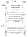
FIG. 2 is a sequence diagram depicting one example of operation of the wireless communications system according to a second embodiment; -
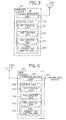
FIG. 3 is a diagram depicting one example of a configuration of a wireless station; -
FIG. 4 is a diagram depicting one example of a configuration of a base station; -
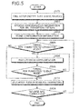
FIG. 5 is a flowchart depicting one example of operation of the wireless station according to the second embodiment; -
FIG. 6 is a flowchart depicting one example of operation of the base station according to the second embodiment; -
FIG. 7 is a sequence diagram depicting one example of operation of obtaining UE capability; -
FIG. 8 is a sequence diagram depicting one example of operation of the wireless communications system according to a fourth embodiment; -
FIG. 9 is a sequence diagram depicting one example of operation of transmission/reception of a MAC CE; -
FIG. 10 is a flowchart depicting one example of operation of the wireless station according to the fourth embodiment; -
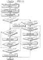
FIG. 11 is a flowchart depicting one example of operation of the base station according to the fourth embodiment; -
FIG. 12 is a diagram of one example a hardware configuration of the wireless station; and -
FIG. 13 is a diagram depicting one example of a hardware configuration of the base station. - Embodiments of a wireless communications system, a wireless station, a base station, and a communications method according to the present invention will be described in detail with reference to the accompanying drawings.
-
FIG. 1 is a sequence diagram depicting one example of operation of the wireless communications system according to a first embodiment. The wireless communications system according to the first embodiment includes awireless station 101 and abase station 102 depicted inFIG. 1 . Thebase station 102 is, for example, an evolved Node B (eNB) or a Home eNB which deploys a femtocell. Thewireless station 101 is, for example, a mobile station such as a user terminal (User Equipment (UE)). Thewireless station 101 and thebase station 102 wirelessly communication with each other. - The
wireless station 101 transmits to thebase station 102, a first control signal that includes classifying information (step S101). Classifying information is information indicating that thewireless station 101 is a specific classification (e.g., a static device). - The
base station 102 transmits to thewireless station 101, a second control signal that configures the timing of transition to the communication mode (step S102). More specifically, thebase station 102 determines the timing of transition of thewireless station 101 and thebase station 102 to the first mode. Thebase station 102 transmits to thewireless station 101, the second control signal that indicates the determined timing of transition. The first mode is a communication mode in which data communication is possible, e.g., the connected mode (connected). The timing of transition to the first mode includes multiple transition timings and for example, is the timing of a constant cycle. Thewireless station 101 and thebase station 102 respectively configure therein, the transition timing indicated by the second control signal transmitted at step S102 (step S103). - The
wireless station 101 and thebase station 102 transition to the first mode (step S104). Thewireless station 101 and thebase station 102 perform data communication with each other (step S105). Thewireless station 101 and thebase station 102 transition to a second mode (step S106). The second mode is a non-communication mode in which data communication is not possible, e.g., the idle mode (idle). - When the transition timing configured at step S103 arrives, the
wireless station 101 and thebase station 102 transition to the first mode in which data communication is possible (step S107). Thewireless station 101 and thebase station 102 perform data communication with each other (step S108). Thewireless station 101 and thebase station 102 transition to the second mode in which data communication is not possible (step S109). Subsequently, thewireless station 101 and thebase station 102 execute steps S107 to S109, each time the transition timing configured at step S103 arrives. - The
base station 102 transmits a third control signal to thewireless station 101, at an arbitrary timing (step S110). The third control signal is a signal instructing release of the transition timing configured at step S103. Thewireless station 101 and thebase station 102 release the transition timing configured at step S103 (step S111), ending a series of operations. - Thus, at the predetermined transition timing (step S102, S103), the
wireless station 101 and thebase station 102 transition to the first mode, thereby enabling reduction of the control signal overhead accompanying state transition. For example, at step S107, notification of the timing of transition to the first mode does not have to be newly given to thewireless station 101 from thebase station 102, thereby enabling reduction of the control signal overhead accompanying state transition and facilitating communication efficiency. For example, reduction of the power consumption of thewireless station 101 and thebase station 102 can be facilitated. - The
wireless station 101 is, for example, a wireless communications apparatus that periodically transmits a small amount of data. In this case, if notification of the timing of transition to the first mode is given to thewireless station 101 by thebase station 102 each time data is transmitted, the control signal overhead for the data to be transmitted becomes large, making efficient communication impossible. In contrast, at the predetermined transition timing (step S102, S103), thewireless station 101 and thebase station 102 transition to the first mode multiple times, whereby the control signal overhead for the data to be transmitted becomes relatively smaller, enabling efficient communications. - Further, the
wireless station 101 and thebase station 102 may store a wireless parameter used in the data communication at step S105. A wireless parameter is, for example, a parameter that indicates a communication scheme such as a modulation scheme or coding scheme. Thewireless station 101 and thebase station 102 also use the stored wireless parameter in the data communication at step S108. Thus, thewireless station 101 and thebase station 102 can communicate data at multiple timings, by the same wireless parameter. As a result, the control signal overhead accompanying state transition can be reduced. - For example, notification of the wireless parameter used in the data communication at step S108 does not have to be given to the
wireless station 101 by thebase station 102, thereby enabling reduction of the control signal overhead accompanying state transition. Further, since random access does not have to be performed for the data communication at step S108, reduction of the control signal overhead accompanying state transition is possible. Therefore, communication efficiency can be facilitated. - The
wireless station 101 is, for example, a stationary wireless communications apparatus that is fixed at a given location and performs wireless communication. In this case, changes in the wireless environment of thewireless station 101 and thebase station 102 are small and therefore, even if the wireless parameter is not updated each time data is communicated, stable wireless communication can be performed between thewireless station 101 and thebase station 102. - The data communication at steps S105, S108 may be the transmission of uplink data from the
wireless station 101 to thebase station 102, or the transmission of downlink data from thebase station 102 to thewireless station 101. Further, the data communication at steps S105, S108 may be both the transmission of uplink data from thewireless station 101 to thebase station 102 and the transmission of downlink data from thebase station 102 to thewireless station 101. - Thus, according to the wireless communications system of the first embodiment, the
base station 102, after receiving the first control signal that includes classifying information indicating the classification of thewireless station 101, configures the communication mode transition timing via the second control signal. Further, the configured communication mode transition timing is released by the third control signal transmitted by thebase station 102. As a result, when thewireless station 101 is of a given classification, the control signal overhead accompanying state transition is reduced, enabling communication efficiency to be facilitated. For example, reduced power consumption of thewireless station 101 and thebase station 102 can be facilitated. - Here, as one example, a wireless communications system that includes the
wireless station 101 and thebase station 102 has been described. Nonetheless, architecture of the wireless communications system is not limited hereto. For example, in the wireless communications system depicted inFIG. 1 , another example of architecture may be such that a relay station is deployed in place of thewireless station 101. Alternatively, in the wireless communications system depicted inFIG. 1 , a relay station may be deployed in place of thebase station 102. - Further, although a case has been described where the transition timing of the
wireless station 101 and thebase station 102 is configured by the transmission of the second control signal from thebase station 102 to thewireless station 101, operation is not limited hereto. For example, the transition timing of thewireless station 101 and thebase station 102 may be configured by the transmission of the second control signal from thewireless station 101 to thebase station 102. In this case, the transition timing of thewireless station 101 and thebase station 102 is determined by thewireless station 101. - Further, although a case has been described where the configuration of the transition timing is released by the transmission of the third control signal from the
base station 102 to thewireless station 101, operation is not limited hereto. For example, the configuration of the transition timing may be released by the transmission of the third control signal from thewireless station 101 to thebase station 102. In this case, the timing at which the configured transition timing is released is determined by thewireless station 101. - One example of a system to which the wireless communications system depicted in
FIG. 1 is applied will be described. The wireless communications system depicted inFIG. 1 is, for example, applicable to Long Term Evolution (LTE). Under LTE, a scheme based on orthogonal frequency division multiplexing (OFDM) is specified as a wireless access technique. - Under LTE, high-speed, wireless packet communication is possible, where the peak downlink transmission rate is 100 [Mb/s] or greater, and the peak uplink transmission rate is 50 [Mb/s] or greater. Aiming to realize even faster communication, the 3rd Generation Partnership Project (3GPP), an international standardizing body, has begun investigating LTE-Advanced (LTE-A) for wireless mobile communications systems, based on LTE.
- The wireless communications system depicted in
FIG. 1 can be applied to LTE-A. Under LTE-A, a peak downlink transmission rate of 1 [Gb/s] is targeted, a peak uplink transmission rate of 500 [Mb/s] is targeted, and technological investigation of wireless access schemes and network architecture is being conducted. - Under LTE-A (or LTE Rel-11), wireless stations which generate traffic that differs from the traffic observed in conventional systems are connected. For example, communication is assumed where various types of stationary, static devices such as electricity meters including sensors and gas meters are connected to a cellular network and perform communication. Such communication is called machine-type communication.
- Communication with a fixed timing can be given as one characteristic of traffic occurring with machine-type communication. For example, an electricity meter and a gas meter periodically transmit to a server, reports concerning the amount of electricity and gas used. Relatively low traffic volume is another quality of the traffic occurring with machine-type communication.
- Yet another characteristic of the traffic occurring with machine-type communication is that the static devices do not move, eliminating the importance of system design that considers mobility, which is the point of mobile communication.
-
FIG. 2 is a sequence diagram depicting one example of operation of the wireless communications system according to a second embodiment. Thewireless station 101 and thebase station 102 of the wireless communications system according to the second embodiment, for example, execute the following steps. During the initial state, thewireless station 101 and thebase station 102 are both assumed to be in an idle state. - When
data 111 that is to be transmitted to thebase station 102 arrives, thewireless station 101 transmits a random access preamble to the base station 102 (step S201). In response, thebase station 102 determines based on the reception timing of the random access preamble, the transmission timing of the uplink signal from thewireless station 101. The determination of the transmission timing of the uplink signal from thewireless station 101 can be performed, for example, based on a timing difference of a reception window of thebase station 102 and the timing at which the preamble is received. Thebase station 102 transmits to thewireless station 101, a random access response that includes information indicating the determined transmission timing (step S202). - Consequent to the random access procedures at steps S201, S202, synchronization is established in the L1 layer (physical layer) and L2 layer (media access control layer) of the
wireless station 101 and thebase station 102. - The
wireless station 101 transmits to thebase station 102, a call connection request (RRC connection request) that includes an identifier of thewireless station 101 and the reason for connection (step S203). Further, thewireless station 101, via the RRC connection request at step S203, notifies thebase station 102 that thewireless station 101 is a static device. - Thus, based on the identifier of the
wireless station 101 obtained from the RRC connection request, thebase station 102 identifies the wireless station that has come to be connected. In an attempt to setup RRC, thebase station 102 transmits to thewireless station 101, a call connection setup (RRC connection setup) that includes a wireless parameter (step S204). The wireless parameter is, for example, a parameter that indicates the communications scheme such as a modulation scheme or a coding scheme. Further, by the RRC connection setup at step S204, thebase station 102 notifies thewireless station 101 of the timing of transition to the connected mode from the idle mode. - In response, when the configuration of the wireless parameter included in the RRC connection setup is completed, the
wireless station 101 transitions to step S205. In other words, thewireless station 101 transmits call connection setup complete (RRC connection setup complete) to the base station 102 (step S205). As a result, RRC connection between thewireless station 101 and thebase station 102 is established, and the RRC state of thewireless station 101 and thebase station 102 transitions to the connected mode from the idle mode. - Next, the
base station 102 transmits to thewireless station 101, RRC connection reconfiguration for configuring reconnection (step S206). Next, thewireless station 101 transmits RRC connection reconfiguration complete to the base station 102 (step S207). - The
wireless station 101 and thebase station 102 execute data communication (step S208). For example, at step S208, thedata 111 arising at step S201 is transmitted from thewireless station 101 to thebase station 102. Subsequently, thewireless station 101 and thebase station 102 transition from the connected mode to the idle mode. - Next,
new data 112 that is to be transmitted to thebase station 102 is assumed to arrive at thewireless station 101. Thus, thewireless station 101 waits until the timing for the transition to the connected mode, notified at step S204. Thewireless station 101 transmits to thebase station 102, a RRC connection re-establishment request that is a request for reconnection (step S209). Consequently, thewireless station 101 and thebase station 102 transition to the connected mode from the idle mode. - Next, the
base station 102 transmits RRC connection re-establishment to the wireless station 101 (step S210). Thewireless station 101 and thebase station 102 execute data communication (step S211). For example, at step S211, thedata 112 arising at step S209 is transmitted from thewireless station 101 to thebase station 102. Subsequently, thewireless station 101 and thebase station 102 transition to the idle mode from the connected mode. - In the case of a transition, a request to re-establish connection is issued to establish security. More specifically, the
wireless station 101 transmits to thebase station 102, a parameter related to security, via an RRC connection re-establishment request. Thus, it is desirable that thewireless station 101, even while in the idle mode, stores to the memory, these parameters related to security. - The parameters related to security, for example, include a cell-radio network temporary identity (C-RNTI), a short message authentication code for integrity (short MAC-I), a physical cell identity (PCID), etc.
- A short MAC-I is a parameter used for verifying integrity of data (verifying that information is without errors). The short MAC-I, for example, is included in the RRC connection re-establishment request at step S209. The
base station 102 uses the MAC-I to verify the integrity of RRC connection re-establishment request. - The short MAC-I, for example, is generated by calculating the ID of the cell in which the
wireless station 101 is located or the C-RNTI of thewireless station 101 by a security algorithm shared by thewireless station 101 and thebase station 102. The ID of the cell in which thewireless station 101 is located, for example, includes the ID of the cell in which thewireless station 101 was located before issuing the RRC connection re-establishment request and/or the ID of the cell in which thewireless station 101 was located when issuing the RRC connection re-establishment request. - For the notification that the
wireless station 101 is a static device at step S203, for example, a "delay Tolerant Access-v1020" in the RRC connection request can be used. Further, for the notification that thewireless station 101 is a static device, a parameter newly specified the RRC connection request may be used. For example, "nm-Access" (non mobile access) may be specified in the "spare2" field of the RRC connection request, whereby notification that thewireless station 101 is a static device is given by "nm-Access". - The timing of transition from the connected mode to the idle mode, for example, can be the timing when a constant period elapses after the transition from the idle mode to the connected mode. In this case, the data communication at steps S208, S211 is completed by the time the constant period elapses after the transition from the idle mode to the connected mode.
- Alternatively, the timing of transition from the connected mode to the idle mode can be the timing at which data is transmitted/received after a given period or greater during the connected mode. For example, during the connected mode, the
wireless station 101 and thebase station 102 restart a timer at each transmission/reception of data and when the timer expires, transition to the idle mode. Thus, the period during which the connected mode is maintained can be established according to the state of communication. - Further, the RRC connection reconfiguration at step S206 may be used in the notification of the timing of the transition to the connected mode from the idle mode. When notification of the timing of transition to the connected mode from the idle mode is given, notification of the timing of transition from the connected mode to the idle mode may also be given to the
wireless station 101 by thebase station 102. -
FIG. 3 is a diagram depicting one example of a configuration of the wireless station. As depicted inFIG. 3 , thewireless station 101, for example, includes acontrol unit 310, acommunications unit 321, and anantenna 322. Thecommunications unit 321, via theantenna 322, performs transmission/reception processing of wirelessly transmitted signals. Thecommunications unit 321, for example, processes radio frequency (RF) signals. - The
control unit 310 performs various types of control of thewireless station 101. Thecontrol unit 310, for example, is a baseband processing unit that processes baseband signals. Thecontrol unit 310 includes aPHY control unit 311, aMAC control unit 312, anRRC control unit 313, and a callconnection control unit 314. - The
PHY control unit 311 processes signals when wireless transmission is performed. For example, thePHY control unit 311 performs wireless transmission according to the modulation and coding of a wireless signal notified by thebase station 102. TheMAC control unit 312 performs a process related to data scheduling based on wireless resources and timings instructed by thebase station 102. - The
RRC control unit 313 controls the operation of thewireless station 101. For example, theRRC control unit 313 configures the wireless resource parameter (e.g., call setup) used for communication, and manages the communication state of thewireless station 101. Further, theRRC control unit 313 performs a process to transition from the RRC idle mode to the RRC connected mode to enable communication, a handover process to connect to a suitable base station, etc. Further, theRRC control unit 313 performs a process of notifying thebase station 102 that thewireless station 101 is a static device, via the RRC connection request. - The call
connection control unit 314 controls management of the RRC state by theRRC control unit 313, according to the classification of thewireless station 101 and traffic type. -
FIG. 4 is a diagram depicting one example of a configuration of the base station. As depicted inFIG. 4 , thebase station 102 includes acontrol unit 410, acommunications unit 421, anantenna 422, and a physical-line interface 423. Thecommunications unit 421 transmits and receives wirelessly transmitted signals, via theantenna 422. Via the physical-line interface 423, thecommunications unit 421 further transmits and receives signals transmitted by a physical line for communication with higher level devices. Thecommunications unit 421, for example, performs transmission/reception processing of RF signals. - The
control unit 410 performs various types of control of the base station 10. Thecontrol unit 410, for example, is a baseband processing unit that processes baseband signals. Thecontrol unit 410 includes aPHY control unit 411, aMAC control unit 412, anRRC control unit 413, and a callconnection control unit 414. - The
PHY control unit 411 processes signals when wireless transmission is performed. For example, thePHY control unit 411 determines the modulation and coding scheme of wireless signals. TheMAC control unit 412 performs a process related to data scheduling. - The
RRC control unit 413 controls the operation of thebase station 102. For example, theRRC control unit 413 configures the wireless resource parameter (e.g., call setup) used for communication, and manages the communication state of thebase station 102. For example, theRRC control unit 413 performs a process to transition from the idle mode to the connected mode to enable communication, and a handover process for connection to a suitable base station. Further, theRRC control unit 413 obtains, by RRC connection request, information indicating that thewireless station 101 is a static device. - The call
connection control unit 414 identifies the classification of thewireless station 101 and traffic type, and controls the management of the RRC state, based on the identification results. -
FIG. 5 is a flowchart depicting one example of operation of the wireless station according to the second embodiment. Thewireless station 101, for example, executes the following steps. Thewireless station 101 performs call setup with the base station 102 (step S501). The call setup at step S501, for example, corresponds to the operations at steps S201 to S205 depicted in theFIG. 2 . Further, thewireless station 101, via the RRC connection request in the call setup at step S501, notifies thebase station 102 that thewireless station 101 is a static device. - The
wireless station 101 receives from thebase station 102, configuration information for an RRC transition pattern (step S502). An RRC transition pattern is, for example, the transition timing of the RRC state. Thewireless station 101 stores to the memory, the configuration information received at the step S502, for the RRC transition pattern (step S503). - The
wireless station 101 judges based on the configuration information stored at step S503, whether the current time is the transition timing for transitioning to the connected mode (step S504). If the current time is not the transition timing for transitioning to the connected mode (step S504: NO), thewireless station 101 proceeds to step S507. - At step S504, if the current time is the transition timing for transitioning to the connected mode (step S504: YES), the
wireless station 101 transitions to the connected mode and executes data communication with the base station 102 (step S505). The data communication at step S505, for example, includes the scheduling of data communication by theMAC control unit 312, the transmission or reception of radio waves by thePHY control unit 311, etc. - The
wireless station 101 judges based on the configuration information stored at step S503, whether the current time is the transition timing for transitioning to the idle mode (step S506). If the current time is not the transition timing for transitioning to the idle mode (step S506: NO), thewireless station 101 returns to step S505, and continues perform the data communication. - At step S506, if the current time is the transition timing for transitioning to the idle mode (step S506: YES), the
wireless station 101 transitions to the idle mode (step S507). Here, thewireless station 101 retains the wireless parameter configured in the call setup at step S501, and uses the same wireless parameter in the next transition to the connected mode. At step S507, if thewireless station 101 is already in the idle mode, thewireless station 101 maintains the idle mode. - The
wireless station 101 judges whether to release (detach) a non-access stratum (NAS) connection (step S508). If the NAS connection is not to be released (step S508: NO), thewireless station 101 returns to step S504. If the NAS connection is to be released (step S508: YES), thewireless station 101 ends a series of operations. -
FIG. 6 is a flowchart depicting one example of operation of the base station according to the second embodiment. Thebase station 102, for example, executes the following steps. Thebase station 102 performs call setup with the wireless station 101 (step S601). The call setup at step S601, for example, corresponds to the operations at steps S201 to S205 depicted inFIG. 2 . Further, thebase station 102, via the RRC connection request in the call setup at step S601, obtains from thewireless station 101, information indicating whether thewireless station 101 is a static device. - The
base station 102 judges based on the information obtained in the call setup at step S601, whether thewireless station 101 is a static device (step S602). If thewireless station 101 is a static device (step S602: YES), thebase station 102 transmits to thewireless station 101, configuration information for the RRC transition pattern (step S603). The RRC transition pattern is, for example, the transition timing of the RRC state. Next, thebase station 102 stores to the memory, the configuration information transmitted at the step S603, for RRC transition pattern (step S604). - The
base station 102 judges based on the configuration information stored at step S604, whether the current time is the transition timing for transitioning to the connected mode (step S605). If the current time is not the transition timing for transitioning to the connected mode (step S605: NO), thebase station 102 proceeds to step S608. - At step S605, if the current time is the transition timing for transitioning to the connected mode (step S605: YES), the
base station 102 judges that thewireless station 101 has transitioned to the connected mode and executes data communication with the wireless station 101 (step S606). The data communication at step S606, for example, includes the scheduling of data communication by theMAC control unit 412, and the transmission or the reception of radio waves by thePHY control unit 411. - The
base station 102 judges based on the configuration information stored at step S604, whether the current time is the transition timing for thewireless station 101 to transition to the idle mode (step S607). If the current time is not the transition timing for thewireless station 101 to transition to the idle mode (step S607: NO), thebase station 102 returns to step S606 and continues to perform the data communication. - At step S607, if the current time is the transition timing for transitioning to the idle mode (step S607: YES), the
base station 102 judges that thewireless station 101 has transitioned to the idle mode (step S608). Here, thebase station 102 retains the wireless parameter configured in the call setup at step S601, and uses the same wireless parameter in the next transition to the connected mode. At step S608, if thewireless station 101 is already in the idle mode, thebase station 102 maintains the idle mode. - The
base station 102 judges whether to release (detach) the NAS connection (step S609). If the NAS connection is not to be released (step S609: NO), thebase station 102 returns to step S605. If the NAS connection is to be released (step S609: YES), thebase station 102 ends a series of operations. - At step S602, if the
wireless station 101 is not a static device (step S602: NO), thebase station 102 judges whether thewireless station 101 transitions to the connected mode (step S610). At step S610, judgment of whether to transition to the connected mode can be performed, for example, based on whether there is a connection request from thewireless station 101. If thewireless station 101 is judged not to transition to the connected mode (step S610: NO), thebase station 102 proceeds to step S614. - At step S610, if the
wireless station 101 is judged to transition to the connected mode (step S610: YES), thebase station 102 judges that thewireless station 101 has transitioned to the connected mode, and executes data communication with the wireless station 101 (step S611). The data communication at step S610, for example, includes the scheduling of data communication by theMAC control unit 412, the transmission or reception of radio waves by thePHY control unit 411, etc. - The
base station 102 judges whether thewireless station 101 transitions to the idle mode (step S612). If thewireless station 101 is judged to not transition to the idle mode (step S612: NO), thebase station 102 returns to step S611 and continues to perform the data communication. - At step S612, if the
wireless station 101 is judged to transition to the idle mode (step S612: YES), thebase station 102 transmits to thewireless station 101, an RRC connection release, and thewireless station 101 transitions to the idle mode (step S613). - The
base station 102 judges whether to release the NAS connection (step S614). If the NAS connection is not to be released (step S614: NO), thebase station 102 returns to step S610. If the NAS connection is to be released (step S614: YES), thebase station 102 transmits to thewireless station 101, a control signal instructing the release of the NAS connection, and ends a series of operations. - In this manner, according to the wireless communications system of the second embodiment, the
base station 102 receives from thewireless station 101, a RRC connection request (first control signal) that includes classifying information indicating that thewireless station 101 is a static device (specific classification). In this case, thebase station 102 configures, via RRC connection setup or RRC connection reconfiguration (second control signal), the transition timing for transitioning to the connected mode (communication mode). Further, the transition to the configured communication mode is released by a control signal (third control signal) instructing the release of the NAS connection. As a result, if thewireless station 101 is not a static device, the RRC control signal overhead accompanying state transition is reduced, enabling communication efficiency to be facilitated. - In the wireless communications system according to a third embodiment, portions differing from the wireless communications system according to the second embodiment will be described.
- The
wireless station 101 according to the third embodiment notifies thebase station 102 that thewireless station 101 is a static device, via UE capability. UE capability is, for example, specified under LTE Rel-10, and is information that notifies thebase station 102, to which category thewireless station 101 belongs. As a result, thewireless station 101 can notify thebase station 102 of the communication performance of thewireless station 101. - For example, a category, "Category 9" can be newly configured for a static device, and the value of the data size can be configured to be smaller (e.g., 1/8) than that of "Category 1". The
wireless station 101 transmits to thebase station 102, the UE capability, which indicates "Category 9". As a result, thebase station 102 can judge that thewireless station 101 is a static device having a communication data size that is small. -
FIG. 7 is a sequence diagram depicting one example of operation of obtaining the UE capability. Thewireless station 101 and thebase station 102, for example, execute the following steps at the time of call setup, for example. Thebase station 102 transmits to thewireless station 101, a UE capability enquiry requesting the UE capability (step S701). - The
wireless station 101 transmits to thebase station 102, UE capability enquiry information that includes "Category 9" (step S702). As a result, thebase station 102 obtains the UE capability indicating "Category 9", and thebase station 102 can judge that thewireless station 101 is a static device. - In this manner, according to the wireless communications system of the third embodiment, the
wireless station 101 can notify thebase station 102, that thewireless station 101 is a static device, via the UE capability. - In the wireless communications system according a fourth embodiment, portions differing from the wireless communications system according to the second embodiment or the third embodiment will be described.
- Even if the
wireless station 101 is a static device, the static device may not always be static such as in the case of a health meter or security sensor. Thus, thebase station 102 transmits activation signals (Activation) and deactivation signals (Deactivation) to thewireless station 101. Activation is a signal instructing transition to a mode of performing state transition by a preconfigured timing. Deactivation is a third control signal instructing transition to a mode of configuring the transition timing for each data communication and performing state transition. - For example, even if the
wireless station 101 is not a static device and "Category 9" is set in the category of the UE capability, thebase station 102 can judge that the volume of data transmitted from thewireless station 101 is small. In this case, by transmitting Activation to thewireless station 101, thebase station 102 can transition to the mode of performing state transition by a preconfigured timing, even if thewireless station 101 is not a static device. - Further, although the
base station 102 performs communication by a mode of performing state transition by a preconfigured timing, if a mode of configuring the transition timing at each data communication and performing state transition is transitioned to, Deactivation is transmitted to thewireless station 101. - The transmission of Activation or Deactivation from the
base station 102, for example, can be performed by the transmission of a physical downlink control channel (PDCCH) by thePHY control unit 411 or theMAC control unit 412. The reception of Activation or Deactivation by thewireless station 101, for example, can be performed by the reception of the PDCCH by thePHY control unit 311 or theMAC control unit 312. -
FIG. 8 is a sequence diagram depicting one example of operation of the wireless communications system according to the fourth embodiment. Thewireless station 101 and thebase station 102 of the wireless communications system according to the fourth embodiment, for example, execute the following steps. In the initial state, thewireless station 101 and thebase station 102 are respectively in the idle mode (Idle). - Steps S801 to S805 depicted in
FIG. 8 are identical to steps S201 to S205 depicted inFIG. 2 . After step S805, thebase station 102 transmits Activation to the wireless station 101 (step S806). As a result, thewireless station 101 and thebase station 102 transition to the mode of performing state transition by a preconfigured timing. - Steps S807 to S812 depicted in
FIG. 8 are identical to steps S206 to S211 depicted inFIG. 2 . After step S812, thebase station 102 transmits Deactivation to the wireless station 101 (step S813). As a result, the mode of performing state transition by a preconfigured timing is released, and thewireless station 101 and thebase station 102 transition to the mode of configuring the transition timing at each data communication and performing state transition. - A PDCCH can be used at the control signal giving notification of Activation and Deactivation, for example. Alternatively, a MAC control element (CE) can be used as the control signal giving notification of Activation and Deactivation.
-
FIG. 9 is a sequence diagram depicting one example of operation of transmission/reception of a MAC CE. When a MAC CE is used as the control signal giving notification of Activation and Deactivation, thewireless station 101 and thebase station 102, for example, execute the following steps. - If the
wireless station 101 is not a static device and "Category 9" is set in the category of the UE capability, thebase station 102 transmits to thewireless station 101, a MAC CE giving notification of Activation (step S901). Thewireless station 101 transmits to thebase station 102, an ACK, which is a response signal for the MAC CE transmitted at step S901 (step S902). As a result, thewireless station 101 and thebase station 102 transition to the mode of performing state transition by a preconfigured timing. - Further, if the mode of performing state transition by a preconfigured timing is to be terminated, the
base station 102 transmits to thewireless station 101, a MAC CE giving notification of Deactivation (step S903). Thewireless station 101 transmits to thebase station 102, an ACK, which is a response signal for the MAC CE transmitted at step S903 (step S904). As a result, thewireless station 101 and thebase station 102 transition to the mode of configuring the transition timing at each data communication and performing state transition. -
FIG. 10 is a flowchart depicting one example of operation of the wireless station according to the fourth embodiment. If thewireless station 101 is static device, thewireless station 101 according to the fourth embodiment, for example, executes the steps depicted inFIG. 5 . If thewireless station 101 is not a static device, thewireless station 101 according to the fourth embodiment, for example, executes the following steps. Steps S1001 to S1003 depicted inFIG. 10 are identical to steps S501 to S503 depicted inFIG. 5 . However, at step S1001, thewireless station 101 does not notify thebase station 102 that thewireless station 101 is a static device. - After step S1003, the
wireless station 101 judges whether Activation via a PDCCH has been received from the base station 102 (step S1004). If Activation has not been received (step S1004: NO), thewireless station 101 ends a series of operations. If Activation has been received (step S1004: YES), thewireless station 101 proceeds to step S1005. Steps S1005 to S1007 depicted inFIG. 10 are identical to steps S504 to S506 depicted inFIG. 5 . - At step S1007, if the transition timing for transitioning to the idle mode has arrived (step S1007: YES), the
wireless station 101 judges whether Deactivation via a PDCCH has been received from the base station 102 (step S1008). If Deactivation has not been received (step S1008: NO), thewireless station 101 returns to step S1005. As a result, thewireless station 101 retains the wireless parameter configured in the call setup at step S1001, and uses the same wireless parameter for the next transition to the connected mode. If Deactivation has been received (step S1008: YES), thewireless station 101 ends a series of operations. -
FIG. 11 is a flowchart depicting one example of operation of the base station according to the fourth embodiment. Thebase station 102 according to the fourth embodiment, for example, executes the following steps. Thebase station 102 performs call setup with the wireless station 101 (step S1101). The call setup at step S1101, for example, corresponds to the operations at steps S201 to S205 depicted inFIG. 2 . Further, via the RRC connection request in the call setup at step S1101, thebase station 102 obtains from thewireless station 101, information indicating whether thewireless station 101 is a static device. - The
base station 102 transmits preconfiguration information of a RRC transition pattern to the wireless station 101 (step S1102). The RRC transition pattern is, for example, the transition timing of the RRC state. Thebase station 102 stores to the memory, the configuration information of the RRC transition pattern, transmitted at step S1102 (step S1103). Thebase station 102 judges based on the information obtained at step S1101, whether thewireless station 101 is a static device (step S1104). If thewireless station 101 is a static device (step S1104: YES), thebase station 102 proceeds to step S1105. Steps S1105 to S1107 are identical to steps S605 to S607 depicted inFIG. 6 . - At step S1107, if the transition timing for transitioning to the idle mode has arrived (step S1007: YES), the
base station 102 judges whether to transmit Deactivation (step S1108). Judgment of whether to transmit Deactivation to thewireless station 101, for example, can be performed based on a state such as the moving state of thewireless station 101. For example, if thebase station 102 obtains from thewireless station 101, information indicating the traveling speed of thewireless station 101 and the traveling speed of thewireless station 101 exceeds a threshold, thewireless station 101 is judged to be moving and Deactivation is transmitted. - At step S1108, if Deactivation is not to be transmitted (step S1108: NO), the
base station 102 returns to step S1105. Here, thebase station 102 retains the wireless parameter configured in the call setup at step S1101 and uses the same wireless parameter for the next transition to the connected mode. If Deactivation is to be transmitted (step S1108: YES), thebase station 102 transmits Deactivation to thewireless station 101, via a PDCCH (step S1109), ending a series of operations. - At step S1104, if the
wireless station 101 is not a static device (step S1104: NO), thebase station 102 judges whether to transmit Activation to the wireless station 101 (step S1110). The judgment of whether to transmit Activation to thewireless station 101, for example, can be performed based on a state such as the moving state of thewireless station 101. For example, if thebase station 102 obtains from thewireless station 101, information indicating the traveling speed of thewireless station 101 and the traveling speed of thewireless station 101 is less than or equal to a threshold for a given period or long, thewireless station 101 judges that thewireless station 101 is not moving and transmits Activation. - At step S1110, if Activation is not to be transmitted (step S1110: NO), the
base station 102 proceeds to step S1112. Steps S1112 to S1116 depicted inFIG. 11 are identical to steps S610 to S614 depicted inFIG. 6 . If Activation is to be transmitted (step S1110: YES), thebase station 102 transmits Activation to thewireless station 101, via a PDCCH (step S1111), and proceeds to step S1105. - In this manner, according to the wireless communications system of the fourth embodiment, when the
wireless station 101 is not a static device (the specific classification of a wireless station), the method of transitioning states can be switched according to the state (e.g., moving state) of thewireless station 101. More specifically, a state of performing communication mode transition based on the configuration of the second control signal and a state of performing communication mode transition irrespective of the configuration of the second control signal can be switched between, according to the state of thewireless station 101. - As a result, if the
wireless station 101 is a static device, a mode of state transition can be switched between a mode in which the state transition is performed by a predetermined configuration timing and a mode in which the state transition is performed by configuring the transition timing at each data communication, according to the state of thewireless station 101. For example, if thewireless station 101 is not moving, by configuring the mode of performing state transition by a predetermined configuration timing, communication efficiency can be facilitated. Further, if thewireless station 101 is moving, by configuring the mode of performing state transition by configuration at each data communication, improved communication quality can be facilitated. -
FIG. 12 is a diagram of one example a hardware configuration of the wireless station. Thewireless station 101 of each of the embodiments described above, for example, can be implemented by acommunications apparatus 1200 depicted inFIG. 12 . Thecommunications apparatus 1200 includes adisplay unit 1201, an input unit 1102, acommunications interface 1203, anantenna 1204, awireless communications unit 1205, read-only memory (ROM) 1206, aprocessor 1207, amain memory 1208, and abus 1220. - The
display unit 1201, the input unit 1102, thecommunications interface 1203, thewireless communications unit 1205, theROM 1206, and themain memory 1208 are connected, via thebus 1220, to theprocessor 1207. - The
display unit 1201 is a user interface that displays information for the operator. Thedisplay unit 1201, for example, is a liquid crystal display. The input unit 1102 is a user interface that receives input of information from the operator. The input unit 1102, for example, is a keypad or the like. The operator of thecommunications apparatus 1200 operates thecommunications apparatus 1200 by using thedisplay unit 1201 and the input unit 1102, such as to input a telephone number. - The
communications interface 1203, for example, is a speaker and a microphone, The operator of thecommunications apparatus 1200 uses thecommunications interface 1203 for audio telephone calls. - The
antenna 1204 is connected to thewireless communications unit 1205. Thewireless communications unit 1205 performs wireless communication via theantenna 1204 and under the control of theprocessor 1207. - The
ROM 1206, for example, stores programs for executing various types of processes. Theprocessor 1207 reads out various types of programs stored on theROM 1206, loads the read program onto themain memory 1208, and executes various types of processes. A central processing unit (CPU), a field programmable gate array (FPGA), and the like may be used as theprocessor 1207, for example. - The
antenna 322 depicted inFIG. 3 , for example, may be implemented by theantenna 1204. Thecommunications unit 321 depicted inFIG. 3 , for example, may be implemented by theprocessor 1207 and thewireless communications unit 1205. Thecontrol unit 310 depicted inFIG. 3 , for example, may be implemented by theROM 1206, theprocessor 1207, and themain memory 1208. -
FIG. 13 is a diagram depicting one example of a hardware configuration of the base station. Thebase station 102 according the embodiments described above, for example, may be implemented by acommunications apparatus 1300 depicted inFIG. 13 . Thecommunications apparatus 1300 includes adisplay unit 1301, aninput unit 1302, a communications interface 1303, anantenna 1304, awireless communications unit 1305,ROM 1306, aprocessor 1307,main memory 1308,storage 1309, and abus 1320. - The
display unit 1301, theinput unit 1302, the communications interface 1303, thewireless communications unit 1305, theROM 1306, themain memory 1308, and thestorage 1309 are connected, via thebus 1320, to theprocessor 1307. - The
display unit 1301 is a user interface that displays information for the operator. Thedisplay unit 1301, for example, is a monitor. Theinput unit 1302 is a user interface that receives the input of information from the operator. Theinput unit 1302, for example, is a keyboard. The operator of thecommunications apparatus 1300 operates thecommunications apparatus 1300 by using thedisplay unit 1301 and theinput unit 1302, such as for inputting information for a setup program. - The communications interface 1303, for example, is a communications interface for communicating with higher level stations. The communications interface 1303, for example, is a network interface, an analog/digital converter (ADC), etc.
- The
antenna 1304 is connected to thewireless communications unit 1305. Thewireless communications unit 1305 performs wireless communication, via theantenna 1304 and under the control of theprocessor 1307. - The
ROM 1306, for example, stores programs for executing various types of processes. Theprocessor 1307 reads out various types of programs stored on theROM 1306, loads the read program onto themain memory 1308, and executes various types processes. A CPU, FPGA, and the like may be used as theprocessor 1307, for example. Thestorage 1309, for example, is a storage apparatus such as a hard disk. For example, a function of a buffer is implemented by thestorage 1309 and theprocessor 1307. - The
antenna 422 depicted inFIG. 4 , for example, may be implemented by theantenna 1304. The physical-line interface 423 depicted inFIG. 4 , for example, may be implemented by the communications interface 1303. Thecommunications unit 421 depicted inFIG. 4 , for example, may be implemented by theprocessor 1307 and thewireless communications unit 1305. Thecontrol unit 410 depicted inFIG. 4 , for example, may be implemented by theROM 1306, theprocessor 1307, and themain memory 1308. - As described, the wireless communications system, the wireless station, the base station, and the communications method enable communication efficiency to be facilitated.
- In the mode of performing state transition by a preconfigured timing, the
wireless station 101, which is a static device, does not move and therefore, although deviation of uplink synchronization is low, the timing of uplink transmission may deviate gradually consequent to the precision of the clock of the static device. Therefore, operation may be such that when a given period has elapsed since the time when the connected mode is entered, thewireless station 101 and thebase station 102 again implement the random access procedure. -
- 101
- wireless station
- 102
- base station
- 111, 112
- data
- 310, 410
- control unit
- 311, 411
- PHY control unit
- 312, 412
- MAC control unit
- 313, 413
- RRC control unit
- 314, 414
- call connection control unit
- 321, 421
- communications unit
- 322, 422, 1204, 1304
- antenna
- 423
- physical-line interface
- 1200, 1300
- communications apparatus
- 1201, 1301
- display unit
- 1202, 1302
- input unit
- 1203, 1303
- communications interface
- 1205, 1305
- wireless communications unit
- 1206, 1306
- ROM
- 1207, 1307
- processor
- 1208, 1308
- main memory
- 1220, 1320
- bus
- 1309
- storage
Claims (11)
- A wireless communications system comprising:a base station; anda wireless station, whereinthe base station, after receiving a first control signal that includes classifying information, configures by a second control signal, transition of a communication mode and releases by a third control signal, the transition of the communication mode, andthe wireless station performs transition of a mode of communication by the communication mode configured by the second control signal, and releases by the third control signal, the transition of the communication mode.
- The wireless communications system according to claim 1, wherein
the first control signal is a signal that is transmitted from the wireless station and indicates that the wireless station is a wireless station of a specific classification. - The wireless communications system according to claim 1 or 2, wherein
the second control signal is a signal that is transmitted from the base station to the wireless station and indicates a plurality of timings for the base station and the wireless station to transition to a data-communication-enabled mode, and
the base station and the wireless station transition to the data-communication-enabled mode, at the plurality of timings indicated by the second control signal. - The wireless communications system according to claim 3, wherein
the base station and the wireless station perform the data communication at the plurality of timings, by a same wireless parameter. - The wireless communications system according to claim 3, wherein
the plurality of timings is a timing of a constant cycle, and
the wireless station periodically transmits data to the base station. - The wireless communications system according to claim 2, wherein
a state of performing the transition of the communication mode based on a configuration of the second control signal and a state of performing the transition of the communication mode irrespective of the configuration of the second control signal are switched between, according to a state of the wireless station and when the wireless station is not a wireless station of the specific classification. - A wireless station that performs wireless communication by preconfiguring transition of a communication mode, the wireless station comprising:a communications unit that transmits to a base station, a first control signal that includes classifying information; receives from the base station, a second control signal that configures the transition of the communication mode; and receives from the base station, a third control signal that releases the transition of the communication mode; anda control unit that performs control such that, after the second control signal is received, performs wireless communication by making the mode transition to the preconfigured communication mode.
- A base station that performs wireless communication by preconfiguring a transition of a communication mode, the base station comprising:a communications unit that receives from a wireless station, a first control signal that includes classifying information; transmits to the wireless station, a second control signal that configures the transition of the communication mode; and transmits to the wireless station, a third control signal that releases the transition of the communication mode; anda control unit that performs control such that after the second control signal is transmitted, performs wireless communication by making the mode transition to the preconfigured communication mode.
- A communications method of a wireless communications system that includes a base station and a wireless station, the communications method comprising:the base station, after receiving a first control signal that includes classifying information, configures a transition of a communication mode by a second control signal and releases the transition of the communication mode by a third control signal; andthe wireless station transits a mode of communication by the second control signal, and releases the transition of the communication mode by the third control signal.
- A communications method of a wireless station that performs wireless communication by preconfiguring a transition of a communication mode, the communications method comprising:transmitting to a base station, a first control signal that includes classifying information; receiving from the base station, a second control signal that configures the transition of the communication mode; and receiving from the base station, a third control signal that releases the transition of the communication mode; andperforming control such that after receiving the second control signal, wireless communication is performed by making the mode transit to the preconfigured communication mode.
- A communications method of a base station that performs wireless communication by preconfiguring transition of a communication mode, the communications method comprising:receiving from the wireless station, a first control signal that includes classifying information; transmitting to the wireless station, a second control signal that configures the transition of the communication mode; and transmitting to the wireless station, a third control signal that releases the transition of the communication mode; andperforming control such that after receiving the second control signal, wireless communication is performed by making the mode transit to the preconfigured communication mode.
Applications Claiming Priority (1)
| Application Number | Priority Date | Filing Date | Title |
|---|---|---|---|
| PCT/JP2012/063818 WO2013179400A1 (en) | 2012-05-29 | 2012-05-29 | Wireless communication system, wireless station, base station and communication method |
Publications (2)
| Publication Number | Publication Date |
|---|---|
| EP2858427A1 true EP2858427A1 (en) | 2015-04-08 |
| EP2858427A4 EP2858427A4 (en) | 2015-12-02 |
Family
ID=49672654
Family Applications (1)
| Application Number | Title | Priority Date | Filing Date |
|---|---|---|---|
| EP12877677.0A Ceased EP2858427A4 (en) | 2012-05-29 | 2012-05-29 | WIRELESS COMMUNICATION SYSTEM, WIRELESS STATION, BASE STATION AND COMMUNICATION METHOD |
Country Status (6)
| Country | Link |
|---|---|
| US (3) | US9736879B2 (en) |
| EP (1) | EP2858427A4 (en) |
| JP (1) | JP6140693B2 (en) |
| KR (3) | KR101723351B1 (en) |
| CN (2) | CN109963355B (en) |
| WO (1) | WO2013179400A1 (en) |
Families Citing this family (5)
| Publication number | Priority date | Publication date | Assignee | Title |
|---|---|---|---|---|
| US10517008B2 (en) * | 2014-09-18 | 2019-12-24 | Sony Corporation | Apparatus |
| US10659976B2 (en) * | 2016-06-29 | 2020-05-19 | Nokia Technologies Oy | Paging enhancement for signaling optimization |
| WO2019176068A1 (en) | 2018-03-15 | 2019-09-19 | 富士通株式会社 | Wireless communication system, base station, mobile station, and wireless communication method |
| JP7039739B2 (en) * | 2019-02-12 | 2022-03-22 | 京セラ株式会社 | Communication control method, user equipment, and base station |
| CN114449687A (en) * | 2020-10-31 | 2022-05-06 | 华为技术有限公司 | Communication method and device |
Family Cites Families (24)
| Publication number | Priority date | Publication date | Assignee | Title |
|---|---|---|---|---|
| JP3166796B2 (en) * | 1992-07-29 | 2001-05-14 | ソニー株式会社 | Cordless phone |
| FI91699C (en) * | 1992-08-14 | 1994-07-25 | Nokia Telecommunications Oy | A method for transmitting user data in packet form in a cellular radio system and a mobile station |
| JP3715197B2 (en) * | 2000-11-20 | 2005-11-09 | 三菱電機株式会社 | Power saving mode transition method and restart method for wireless communication system |
| JP4742842B2 (en) | 2005-12-13 | 2011-08-10 | 富士ゼロックス株式会社 | Image log function display program, image log function display method, image processing apparatus, and image processing system |
| JP5019400B2 (en) | 2006-04-25 | 2012-09-05 | サムスン エレクトロニクス カンパニー リミテッド | Wireless connection setting method and apparatus in mobile communication system |
| JP2008079235A (en) * | 2006-09-25 | 2008-04-03 | Kyocera Corp | Wireless communication system, wireless communication terminal, base station, and wireless communication method |
| US9137844B2 (en) * | 2007-10-04 | 2015-09-15 | Qualcomm Incorporated | Method and apparatus for handling user equipment capability information |
| KR101387480B1 (en) | 2007-01-11 | 2014-04-22 | 엘지전자 주식회사 | method for applying scheduling mechanism based on the communication condition and tranceiver supporting the same |
| JP5059440B2 (en) | 2007-02-09 | 2012-10-24 | 株式会社エヌ・ティ・ティ・ドコモ | Base station apparatus, user apparatus, and radio bearer setting method |
| US8072930B2 (en) * | 2007-04-25 | 2011-12-06 | Sony Corporation | Communication unit, system and method for saving power therein |
| ATE553628T1 (en) * | 2007-11-13 | 2012-04-15 | Research In Motion Ltd | METHOD AND APPARATUS FOR STATUS/MODE TRANSITIONS |
| JP5205093B2 (en) * | 2008-03-21 | 2013-06-05 | 株式会社エヌ・ティ・ティ・ドコモ | User apparatus and base station apparatus |
| JP2010130096A (en) * | 2008-11-25 | 2010-06-10 | Toshiba Corp | Wireless terminal, base station, wireless communication system and wireless communication method |
| EP2498552A4 (en) | 2009-11-02 | 2014-06-25 | Nec Corp | Communication device, communication system, communication device control method, and communication device control program |
| KR101477518B1 (en) * | 2010-01-06 | 2014-12-30 | 한국전자통신연구원 | Machine tyep communication system |
| GB2477118A (en) * | 2010-01-22 | 2011-07-27 | Reckitt Benckiser Corporate Services Ltd | Dynamically adjustable state transition timer |
| KR101674222B1 (en) | 2010-02-09 | 2016-11-09 | 엘지전자 주식회사 | Apparatus and method of reporting logged measurement in wireless communication system |
| JP5505496B2 (en) * | 2010-03-18 | 2014-05-28 | 富士通株式会社 | Wireless terminal device, communication device, wireless communication system, and communication method |
| WO2011129660A2 (en) * | 2010-04-15 | 2011-10-20 | 엘지전자 주식회사 | Method and apparatus for persistent resource allocation in a wireless access system |
| US8744534B2 (en) * | 2010-04-30 | 2014-06-03 | Apple Inc. | Methods and apparatus for preserving battery resources in a mobile communication device |
| CN102387492B (en) * | 2010-08-27 | 2014-01-22 | 上海贝尔股份有限公司 | Characteristic activation of machinery type communication and machinery equipment |
| WO2012034580A1 (en) | 2010-09-13 | 2012-03-22 | Nokia Siemens Networks Oy | Reduced radio resource control connectivity |
| CN102438292B (en) | 2010-09-29 | 2015-06-10 | 中兴通讯股份有限公司 | Radio resource control method and system |
| JP5652098B2 (en) * | 2010-10-04 | 2015-01-14 | ソニー株式会社 | Base station, wireless communication method, program, wireless communication system, and wireless terminal |
-
2012
- 2012-05-29 KR KR1020167010200A patent/KR101723351B1/en active Active
- 2012-05-29 CN CN201811474286.1A patent/CN109963355B/en active Active
- 2012-05-29 JP JP2014518135A patent/JP6140693B2/en active Active
- 2012-05-29 CN CN201280073505.XA patent/CN104350787B/en active Active
- 2012-05-29 KR KR1020177008523A patent/KR101815429B1/en active Active
- 2012-05-29 KR KR1020147032713A patent/KR20150003860A/en not_active Ceased
- 2012-05-29 WO PCT/JP2012/063818 patent/WO2013179400A1/en not_active Ceased
- 2012-05-29 EP EP12877677.0A patent/EP2858427A4/en not_active Ceased
-
2014
- 2014-11-24 US US14/551,441 patent/US9736879B2/en active Active
-
2017
- 2017-04-12 US US15/485,668 patent/US9942940B2/en active Active
-
2018
- 2018-02-22 US US15/902,645 patent/US10206243B2/en active Active
Also Published As
| Publication number | Publication date |
|---|---|
| WO2013179400A1 (en) | 2013-12-05 |
| US10206243B2 (en) | 2019-02-12 |
| CN109963355A (en) | 2019-07-02 |
| JPWO2013179400A1 (en) | 2016-01-14 |
| US20180184483A1 (en) | 2018-06-28 |
| US9736879B2 (en) | 2017-08-15 |
| JP6140693B2 (en) | 2017-05-31 |
| CN104350787A (en) | 2015-02-11 |
| US9942940B2 (en) | 2018-04-10 |
| CN104350787B (en) | 2018-12-18 |
| CN109963355B (en) | 2023-03-28 |
| KR101815429B1 (en) | 2018-01-04 |
| KR101723351B1 (en) | 2017-04-05 |
| US20150080006A1 (en) | 2015-03-19 |
| KR20170038942A (en) | 2017-04-07 |
| KR20160049038A (en) | 2016-05-04 |
| EP2858427A4 (en) | 2015-12-02 |
| KR20150003860A (en) | 2015-01-09 |
| US20170223681A1 (en) | 2017-08-03 |
Similar Documents
| Publication | Publication Date | Title |
|---|---|---|
| CN118176820B (en) | Method and apparatus for small data transmission (SDT) | |
| CA2775343C (en) | System and method for multi-carrier network operation | |
| CA2775371C (en) | System and method for multi-carrier network operation | |
| CN116171605B (en) | Systems and methods for improving paging reception by receiving CSI-RS/TRS indications via UE in idle/inactive mode. | |
| EP3174341A1 (en) | Methods and nodes for setting values of system parameters used in a wireless communication system | |
| US20120294694A1 (en) | Anchoring means | |
| US10206243B2 (en) | Wireless communications system, wireless station, base station, and communications method | |
| EP2962489B1 (en) | Delivery of measurements | |
| CN103999489A (en) | Network synchronisation of devices in a D2D cluster | |
| CN116114281B (en) | Generating a security key for handling data transmissions from a user equipment in an inactive state | |
| WO2022021296A1 (en) | Systems and methods to provide csi-rs/trs indication to ues in idle/inactive mode | |
| WO2011122045A1 (en) | Wireless communication base station, wireless communication device and wireless communication system | |
| EP2749063A1 (en) | Uplink load generation in communication networks | |
| EP2947937A1 (en) | Base station device, communi cation method, and terminal device | |
| JP6519671B2 (en) | Wireless communication system, wireless station and base station | |
| JP6278054B2 (en) | Wireless communication system, wireless station and base station | |
| CN103517399A (en) | Method and apparatus for carrier synchronization |
Legal Events
| Date | Code | Title | Description |
|---|---|---|---|
| PUAI | Public reference made under article 153(3) epc to a published international application that has entered the european phase |
Free format text: ORIGINAL CODE: 0009012 |
|
| 17P | Request for examination filed |
Effective date: 20141222 |
|
| AK | Designated contracting states |
Kind code of ref document: A1 Designated state(s): AL AT BE BG CH CY CZ DE DK EE ES FI FR GB GR HR HU IE IS IT LI LT LU LV MC MK MT NL NO PL PT RO RS SE SI SK SM TR |
|
| AX | Request for extension of the european patent |
Extension state: BA ME |
|
| DAX | Request for extension of the european patent (deleted) | ||
| RA4 | Supplementary search report drawn up and despatched (corrected) |
Effective date: 20151102 |
|
| RIC1 | Information provided on ipc code assigned before grant |
Ipc: H04W 52/02 20090101AFI20151027BHEP Ipc: H04W 76/04 20090101ALI20151027BHEP |
|
| STAA | Information on the status of an ep patent application or granted ep patent |
Free format text: STATUS: EXAMINATION IS IN PROGRESS |
|
| 17Q | First examination report despatched |
Effective date: 20181119 |
|
| REG | Reference to a national code |
Ref country code: DE Ref legal event code: R003 |
|
| STAA | Information on the status of an ep patent application or granted ep patent |
Free format text: STATUS: THE APPLICATION HAS BEEN REFUSED |
|
| 18R | Application refused |
Effective date: 20210322 |