EP2858405A1 - Method and device for determining uplink transmission interruption time - Google Patents
Method and device for determining uplink transmission interruption time Download PDFInfo
- Publication number
- EP2858405A1 EP2858405A1 EP20130800530 EP13800530A EP2858405A1 EP 2858405 A1 EP2858405 A1 EP 2858405A1 EP 20130800530 EP20130800530 EP 20130800530 EP 13800530 A EP13800530 A EP 13800530A EP 2858405 A1 EP2858405 A1 EP 2858405A1
- Authority
- EP
- European Patent Office
- Prior art keywords
- uplink transmission
- interruption time
- transmission interruption
- cell
- tdd
- Prior art date
- Legal status (The legal status is an assumption and is not a legal conclusion. Google has not performed a legal analysis and makes no representation as to the accuracy of the status listed.)
- Granted
Links
Images
Classifications
-
- H—ELECTRICITY
- H04—ELECTRIC COMMUNICATION TECHNIQUE
- H04L—TRANSMISSION OF DIGITAL INFORMATION, e.g. TELEGRAPHIC COMMUNICATION
- H04L43/00—Arrangements for monitoring or testing data switching networks
- H04L43/08—Monitoring or testing based on specific metrics, e.g. QoS, energy consumption or environmental parameters
- H04L43/0823—Errors, e.g. transmission errors
- H04L43/0847—Transmission error
-
- H—ELECTRICITY
- H04—ELECTRIC COMMUNICATION TECHNIQUE
- H04W—WIRELESS COMMUNICATION NETWORKS
- H04W76/00—Connection management
- H04W76/20—Manipulation of established connections
- H04W76/28—Discontinuous transmission [DTX]; Discontinuous reception [DRX]
-
- H—ELECTRICITY
- H04—ELECTRIC COMMUNICATION TECHNIQUE
- H04W—WIRELESS COMMUNICATION NETWORKS
- H04W72/00—Local resource management
- H04W72/20—Control channels or signalling for resource management
- H04W72/21—Control channels or signalling for resource management in the uplink direction of a wireless link, i.e. towards the network
-
- H—ELECTRICITY
- H04—ELECTRIC COMMUNICATION TECHNIQUE
- H04L—TRANSMISSION OF DIGITAL INFORMATION, e.g. TELEGRAPHIC COMMUNICATION
- H04L5/00—Arrangements affording multiple use of the transmission path
- H04L5/0001—Arrangements for dividing the transmission path
- H04L5/0003—Two-dimensional division
- H04L5/0005—Time-frequency
- H04L5/0007—Time-frequency the frequencies being orthogonal, e.g. OFDM(A) or DMT
- H04L5/001—Time-frequency the frequencies being orthogonal, e.g. OFDM(A) or DMT the frequencies being arranged in component carriers
-
- H—ELECTRICITY
- H04—ELECTRIC COMMUNICATION TECHNIQUE
- H04L—TRANSMISSION OF DIGITAL INFORMATION, e.g. TELEGRAPHIC COMMUNICATION
- H04L5/00—Arrangements affording multiple use of the transmission path
- H04L5/14—Two-way operation using the same type of signal, i.e. duplex
- H04L5/1469—Two-way operation using the same type of signal, i.e. duplex using time-sharing
-
- H—ELECTRICITY
- H04—ELECTRIC COMMUNICATION TECHNIQUE
- H04W—WIRELESS COMMUNICATION NETWORKS
- H04W24/00—Supervisory, monitoring or testing arrangements
- H04W24/08—Testing, supervising or monitoring using real traffic
-
- H—ELECTRICITY
- H04—ELECTRIC COMMUNICATION TECHNIQUE
- H04W—WIRELESS COMMUNICATION NETWORKS
- H04W72/00—Local resource management
- H04W72/04—Wireless resource allocation
- H04W72/044—Wireless resource allocation based on the type of the allocated resource
- H04W72/0453—Resources in frequency domain, e.g. a carrier in FDMA
-
- H—ELECTRICITY
- H04—ELECTRIC COMMUNICATION TECHNIQUE
- H04W—WIRELESS COMMUNICATION NETWORKS
- H04W72/00—Local resource management
- H04W72/12—Wireless traffic scheduling
- H04W72/1263—Mapping of traffic onto schedule, e.g. scheduled allocation or multiplexing of flows
-
- H—ELECTRICITY
- H04—ELECTRIC COMMUNICATION TECHNIQUE
- H04W—WIRELESS COMMUNICATION NETWORKS
- H04W74/00—Wireless channel access
- H04W74/002—Transmission of channel access control information
- H04W74/004—Transmission of channel access control information in the uplink, i.e. towards network
-
- H—ELECTRICITY
- H04—ELECTRIC COMMUNICATION TECHNIQUE
- H04W—WIRELESS COMMUNICATION NETWORKS
- H04W8/00—Network data management
- H04W8/22—Processing or transfer of terminal data, e.g. status or physical capabilities
-
- H—ELECTRICITY
- H04—ELECTRIC COMMUNICATION TECHNIQUE
- H04W—WIRELESS COMMUNICATION NETWORKS
- H04W72/00—Local resource management
- H04W72/02—Selection of wireless resources by user or terminal
Definitions
- the present invention relates to the field of communications and particularly to a method and a device for determining uplink transmission interruption time.
- Time Division Duplex (TDD) uplink/downlink (UL/DL) configurations are as depicted in Table 1. Seven kinds of TDD UL/DL configurations are defined for a TDD system in the physical layer standard, where D represents a DL sub-frame, U represents a UL sub-frame, and S represents a special sub-frame of the TDD system. Table 1 TDD UL/DL configurations TDD UL/DL configuration No.
- the TD UL/DL configuration of each cell is determined and can be notified to a User Equipment (UE) in a broadcast message.
- UE User Equipment
- a dynamic TDD UL/DL configuration is supported in the Long Tem Evolution (LTE) system, that is, transmission directions in a part or all of sub-frames in a radio frame are determined as scheduled. For example, if some sub-frame has no UL scheduling signaling or is not configured with a Physical Uplink Control Channel (PUCCH)/Sounding Reference Signal (SRS), then it can be considered as a downlink sub-frame; otherwise, it can be considered as an uplink sub-frame.
- PUCCH Physical Uplink Control Channel
- SRS Sounding Reference Signal
- the Carrier Aggregation (CA) technology has been proposed in the prior art. As compared with the LTE system, the peak rates in the Long Term Evolution-Advanced (LTE-A) are improved significantly, where 1Gbps in the downlink and 500Mbps in the uplink are required.
- LTE-A system is required to be well compatible with the LTE system.
- the carrier aggregation technology has been introduced to the LTE-A system to thereby accommodate the improved peak rates, compatibility with the LTE system and full use of spectrum resources as needed.
- a User Equipment (UE) can operate concurrently over a plurality of cells, where these cells can be consecutive or inconsecutive in frequency, and bandwidths of the respective cells may be the same or different. There is a limited bandwidth up to 20MHz of each cell for compatibility with the LTE system, and the number of cells that can be aggregated by one UE is typically up to 5 at present.
- serving cells configured by an evolved Node B (eNB) for the UE are referred to as serving cells. All the functions of the different serving cells may not be the same, so the serving cells are further categorized in the LTE-A system as follows: a Primary Cell (PCell) and a Secondary Cell (SCell), where only one of the plurality of cells aggregated by the UE is defined as the PCell.
- the PCell is selected by the eNB and configured to the UE in Radio Resource Control (RRC) signaling, and only the PCell is configured with a PUCCH. All the cells except the PCell aggregated by the UE are SCells.
- RRC Radio Resource Control
- the concept of the measurement gap has been proposed in the prior art.
- the LTE system needs to configure the UE to stop receiving and sending data over the current operating band for a period of time and to tune a transceiver to measure the channel quality at a different frequency or in a different system cell, where the period of time is referred to as the measurement gap.
- patterns of the measurement gap are as depicted in Table 2.
- Gap pattern configurations supported by UE Gap pattern Measurement Gap Length (MGL) (in ms) Repetitive periodicity of measurement gap (in ms) Shortest measurement period (in ms) for different frequency or different system in 480 ms 0 6 40 60 1 6 80 30
- the UE determines whether the UE needs the measurement gap when measuring some frequency point depends upon the UE capability.
- the UE signals the UE capability to the eNB in a UE capability report, where a measurement capability in the UE capability report signaling is reported per band combination, that is, a report is made on whether the UE operating in some band combination needs a measurement gap when measuring another band. Since the UE needs to tune the transceiver in the measurement gap to measure at a specified different frequency or frequency of a different system, the uplink/downlink transmission in the current serving cell needs to be interrupted.
- systems of the LTE-A R10 and earlier only support aggregation of cells in the same duplex mode or the same TDD UL/DL configuration by the UE, so the uplink transmission interruption time resulting from the measurement gap is the same for all the cells aggregated by the UE, and once uplink transmission interruption resulting from the measurement gap occurs, the UE can stop uplink transmission over all the cells without distinguishing one cell from another.
- Embodiments of the invention provide a method and a device for determining uplink transmission interruption time so as to determine the uplink transmission interruption time resulting from a measurement gap when cells in different duplex modes or different TDD UL/DL configurations are aggregated by a UE.
- an embodiment of the invention provides a method for determining uplink transmission interruption time, the method including:
- An embodiment of the invention further provides another method for determining uplink transmission interruption time, the method including:
- the uplink transmission interruption time of each cell aggregated by a UE can be determined to thereby determine definitively the uplink transmission interruption time resulting from the measurement gap so that the UE can know how to stop uplink transmission over the respective cells.
- the first embodiment of the invention provides a method for determining uplink transmission interruption time (i.e., uplink transmission interruption time resulting from a measurement gap), which can be applicable to system of the LTE-A R11 and later and in which cells in different duplex modes or different TDD UL/DL configurations are allowed to be aggregated by a UE.
- the method can include a process of determining, by a UE, uplink transmission interruption time and a process of determining, by a base station device, uplink transmission interruption time.
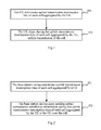
- Fig.1 is a flow chart of determining, by a UE, uplink transmission interruption time. As illustrated in Fig.1 , the method includes the following operations.
- Operation 101 the UE determines uplink transmission interruption time of each cell aggregated by the UE.
- the UE determines the uplink transmission interruption time of each cell aggregated by the UE in the following three approaches without any limitation thereto.
- the uplink transmission interruption time resulting from the measurement gap is determined based upon the UE.
- the UE determines uplink transmission interruption time corresponding to all the cells aggregated by the UE as the uplink transmission interruption time of each cell. For example, when three cells are aggregated by the UE, these three cells correspond to the same uplink transmission interruption time, so the uplink transmission interruption time is determined as the uplink transmission interruption time of each cell.
- the UE determines the uplink transmission interruption time corresponding to all the cells aggregated by the UE as the uplink transmission interruption time of each cell as follows:
- the UE determines uplink transmission interruption time resulting from the measurement gap over each cell aggregated by the UE according to the duplex mode and/or TDD UL/DL configuration of the each cell, and determines a union set or an intersection set of the uplink transmission interruption time over all cells as the uplink transmission interruption time of the each cell; or
- the UE and a base station device prescribe the uplink transmission interruption time resulting from the measurement gap to be (MGL + a specified value) ms
- the UE determines the uplink transmission interruption time of the each cell to be (MGL + the specified value) ms, for example, the specified value is 1ms; or
- the UE determines uplink transmission interruption time resulting from the measurement gap according to a reference duplex mode and/or TDD UL/DL configuration and takes the uplink transmission interruption time as the uplink transmission interruption time of each cell, where the reference duplex mode and/or TDD UL/DL configuration is any one of the following duplex modes and/or TDD UL/DL configurations:
- the explicit signaling can be RRC signaling, MAC signaling or physical layer signaling.
- the uplink transmission interruption time resulting from the measurement gap is associated with the duplex mode(s) and/or the TDD UL/DL configuration(s).
- the uplink transmission interruption time resulting from the measurement gap is MGL plus the first sub-frame subsequent to MGL.
- the uplink transmission interruption time resulting from the measurement gap is MGL plus the first sub-frame subsequent to MGL. In other situations, the uplink transmission interruption time resulting from the measurement gap is MGL.
- this approach in which the uplink transmission interruption time resulting from the measurement gap is determined based upon the UE, can be applicable to full-duplex and half-duplex UEs.
- the uplink transmission interruption time resulting from the measurement gap is determined based upon a set of same duplex configurations.
- the UE determines the uplink transmission interruption time respectively for each cell based upon a set of duplex configurations to which the each cell belongs, where the set of duplex configurations includes at least one aggregated cell, and when the set of duplex configurations includes a plurality of cells, the plurality of cells have the same duplex mode and/or TDD UL/DL configuration.
- each set of same duplex configurations includes one cell, which indicates that the respective cells aggregated by the UE adopt different duplex modes and/or TDD UL/DL configurations
- the event that the UE determines the uplink transmission interruption time respectively for each cell based upon the set of duplex configurations to which the each cell belongs is equivalent to that the UE determines the uplink transmission interruption time corresponding to each cell aggregated by the UE. That is, the uplink transmission interruption time resulting from the measurement gap is determined respectively for each cell according to its duplex mode.
- TDD UL/DL configuration needs to be further taken into account for TDD. For example, when three cells are aggregated by the UE and these three cells adopt different duplex modes and/or TDD UL/DL configurations, each of the three cells corresponds respectively to one uplink transmission interruption time.
- the UE determines the uplink transmission interruption time respectively for each cell based upon the set of duplex configurations to which the each cell belongs as follows: the UE determines uplink transmission interruption time according to a duplex mode and/or TDD UL/DL configuration in the set of duplex configurations, and takes the uplink transmission interruption time as the uplink transmission interruption time of each cell in the set of duplex configurations; or, the UE determines uplink transmission interruption time according to a reference duplex mode and/or TDD UL/DL configuration in the set of duplex configurations, and takes the uplink transmission interruption time as the uplink transmission interruption time of each cell in the set of duplex configurations, where the reference duplex mode and/or TDD UL/DL configuration is any one of the following duplex modes and/or TDD UL/DL configurations:
- the explicit signaling can be RRC signaling, MAC signaling or physical layer signaling.
- the uplink transmission interruption time resulting from the measurement gap is associated with the duplex mode(s) and/or the TDD UL/DL configuration(s).
- the uplink transmission interruption time resulting from the measurement gap is MGL plus the first sub-frame subsequent to MGL.
- the uplink transmission interruption time resulting from the measurement gap is MGL plus the first sub-frame subsequent to MGL. In other situations, the uplink transmission interruption time resulting from the measurement gap is MGL.
- this approach of determining the uplink transmission interruption time resulting from the measurement gap based upon the cell or the set of same duplex configurations can be applicable to the full-duplex UE.
- the uplink transmission interruption time resulting from the measurement gap is determined based upon the transceiver.
- the UE can determine the transceiver required to perform measurements and the aggregated cells served by the transceiver and determine the uplink transmission interruption time respectively for each aggregated cell served by the transceiver, and determine uplink transmission interruption time of aggregated cells served by other transceivers of the UE to be 0, that is, it is not necessary to determine the uplink transmission interruption time for the aggregated cells served by the other transceivers.
- the process of determining, by the UE, the transceiver required to perform measurements includes: when the UE and the base station device prescribe to tune the transceiver supporting the highest frequency, the UE determines the transceiver at the highest frequency as the transceiver required to perform measurements; or when the UE and the base station device prescribe to tune the transceiver supporting the lowest frequency, the UE determines the transceiver at the lowest frequency as the transceiver required to perform measurements; or when the base station device explicitly configures a transceiver to be tuned, the UE receives the explicit configuration information from the base station device to indicate the band corresponding to the transceiver required to perform measurements and determines the transceiver corresponding to the band as the transceiver required to perform measurements.
- the UE determines the uplink transmission interruption time of each aggregated cell served by the transceiver particularly as follows:
- the UE determines the uplink transmission interruption time resulting from the measurement gap over each of the aggregated cells served by the transceiver according to the duplex mode and/or TDD UL/DL configuration of each cell, and takes the determined uplink transmission interruption time as the uplink transmission interruption time corresponding to each cell; or
- the UE determines the uplink transmission interruption time resulting from the measurement gap over each of the aggregated cells served by the transceiver according to the duplex mode and/or TDD UL/DL configuration of each cell, and takes the union set of the uplink transmission interruption time over all the cells as the uplink transmission interruption time of each cell; or
- the UE determines the uplink transmission interruption time resulting from the measurement gap according to the reference duplex mode and/or TDD UL/DL configuration, and takes the uplink transmission interruption time as the uplink transmission interruption time of each aggregated cell served by the transceiver, where the reference duplex mode and/or TDD UL/DL configuration is any one of the following duplex modes and/or TDD UL/DL configurations:
- the explicit signaling can be RRC signaling, MAC signaling or physical layer signaling.
- the uplink transmission interruption time resulting from the measurement gap is associated with the duplex modes and the TDD UL/DL configurations of the cells corresponding to the transceiver or the reference duplex mode and TDD UL/DL configuration used by the cells corresponding to the transceiver.
- the uplink transmission interruption time resulting from the measurement gap is MGL plus the first sub-frame subsequent to MGL.
- the uplink transmission interruption time resulting from the measurement gap is MGL plus the first sub-frame subsequent to MGL. In other situations, the uplink transmission interruption time resulting from the measurement gap is MGL.
- this approach of determining the uplink transmission interruption time resulting from the measurement gap based upon the transceiver can be applicable to the UE with a plurality of transceivers and supporting the full-duplex mode.
- Operation 102 the UE stops, during the uplink transmission interruption time of each cell aggregated by the UE, uplink transmission of the cell.
- the UE stops uplink transmission of all the cells during the determined uplink transmission interruption time without adopting different uplink transmission processes for different cells.
- the UE stops uplink transmission of the cells corresponding to the determined uplink transmission interruption time, which is required to process uplink transmission differently from one cell to another.
- the UE stops uplink transmission of the cells corresponding to the determined transceiver, which is required to adopt different uplink transmission processes for different cells.
- the UE if the uplink transmission interruption time resulting from the measurement gap is determined based upon the UE, then during the uplink transmission interruption time determined based upon the measurement gap, the UE is not allowed for performing any uplink transmission but can process the UL grant.
- the UE stops uplink transmission of the cells as follows: during the uplink transmission interruption time of each cell aggregated by the UE, the UE stops transmitting one or any combination of the following information over the cell: a Physical Uplink Shared Channel (PUSCH), a PUCCH, a Physical Random Access Channel (PRACH) and a Sounding Reference Signal (SRS).
- PUSCH Physical Uplink Shared Channel
- PRACH Physical Random Access Channel
- SRS Sounding Reference Signal
- the PUCCH includes one or any combination of the following information: a Channel Quality Indicator (CQI), a Pre-coding Matrix Indicator (PMI), a Rank Indication (RI), a Scheduling Request (SR) and a Hybrid Automatic Repeat Request (HARQ) feedback.
- CQI Channel Quality Indicator
- PMI Pre-coding Matrix Indicator
- RI Rank Indication
- SR Scheduling Request
- HARQ Hybrid Automatic Repeat Request
- different duplex modes and/or different TDD UL/DL configurations can apply to the cells aggregated by the UE.
- different duplex modes and/or different TDD UL/DL configurations can apply to at least two cells.
- Fig.2 is a flow chart of determining, by a base station device, uplink transmission interruption time. As illustrated in Fig.2 , the method includes the following operations:
- Operation 201 the base station device determines uplink transmission interruption time of each cell aggregated by a UE.
- the base station device determines the uplink transmission interruption time of each cell aggregated by the UE in the following three approaches without any limitation thereto.
- the uplink transmission interruption time resulting from the measurement gap is determined based upon the UE.
- the base station device determines the uplink transmission interruption time corresponding to all the cells aggregated by the UE as the uplink transmission interruption time of each cell. For example, when three cells are aggregated by the UE, these three cells correspond to the same uplink transmission interruption time.
- the base station device determines the uplink transmission interruption time corresponding to all the cells aggregated by the UE as the uplink transmission interruption time of each cell as follows:
- the base station device determines the uplink transmission interruption time resulting from the measurement gap over each cell aggregated by the UE according to the duplex mode and/or TDD UL/DL configuration of the each cell, and determines a union set or an intersection set of the uplink transmission interruption time over all cells as the uplink transmission interruption time of the each cell; or
- the base station device determines the uplink transmission interruption time of each cell to be (MGL + the specified value) ms, for example, the specified value is 1ms; or
- the base station device determines the uplink transmission interruption time resulting from the measurement gap according to the reference duplex mode and/or TDD UL/DL configuration and takes the uplink transmission interruption time as the uplink transmission interruption time of each cell, where the reference duplex mode and/or TDD UL/DL configuration is any one of the following duplex modes and/or TDD UL/DL configurations:
- the explicit signaling can be RRC signaling, MAC signaling or physical layer signaling.
- the uplink transmission interruption time resulting from the measurement gap is associated with the duplex mode(s) and/or the TDD UL/DL configuration(s).
- the uplink transmission interruption time resulting from the measurement gap is MGL plus the first sub-frame subsequent to MGL.
- the uplink transmission interruption time resulting from the measurement gap is MGL plus the first sub-frame subsequent to MGL. In other situations, the uplink transmission interruption time resulting from the measurement gap is MGL.
- this approach in which the uplink transmission interruption time resulting from the measurement gap is determined based upon the UE, can be applicable to full-duplex and half-duplex UEs.
- the uplink transmission interruption time resulting from the measurement gap is determined based upon a set of same duplex configurations.
- the base station device determines the uplink transmission interruption time respectively for each cell based upon a set of duplex configurations to which the each cell belongs, where the set of duplex configurations includes at least one aggregated cell, and when the set of duplex configurations includes a plurality of cells, the plurality of cells have the same duplex mode and/or TDD UL/DL configuration.
- each set of same duplex configurations includes one cell, which indicates that the respective cells aggregated by the UE adopt different duplex modes and/or TDD UL/DL configurations
- the event that the base station device determines the uplink transmission interruption time respectively for each cell based upon the set of duplex configurations to which the each cell belongs is equivalent to that the base station device determines the uplink transmission interruption time corresponding to each cell aggregated by the UE. That is, the uplink transmission interruption time resulting from the measurement gap is determined respectively for each cell or each set of duplex configurations according to its duplex mode.
- TDD UL/DL configuration needs to be further taken into account for TDD. For example, when three cells are aggregated by the UE and these three cells adopt different duplex modes and/or TDD UL/DL configurations, each of the three cells corresponds respectively to one uplink transmission interruption time.
- the base station device determines the uplink transmission interruption time respectively for each cell based upon the set of duplex configurations to which the each cell belongs as follows: the base station device determines uplink transmission interruption time according to a duplex mode and/or TDD UL/DL configuration in the set of duplex configurations, and takes the uplink transmission interruption time as the uplink transmission interruption time of each cell in the set of duplex configurations; or, the base station device determines uplink transmission interruption time according to a reference duplex mode and/or TDD UL/DL configuration in the set of duplex configurations, and takes the uplink transmission interruption time as the uplink transmission interruption time of each cell in the set of duplex configurations, where the reference duplex mode and/or TDD UL/DL configuration is any one of the following duplex modes and/or TDD UL/DL configurations:
- the explicit signaling can be RRC signaling, MAC signaling or physical layer signaling.
- the uplink transmission interruption time resulting from the measurement gap is associated with the duplex mode(s) and/or the TDD UL/DL configuration(s).
- the uplink transmission interruption time resulting from the measurement gap is MGL plus the first sub-frame subsequent to MGL.
- the uplink transmission interruption time resulting from the measurement gap is MGL plus the first sub-frame subsequent to MGL. In other situations, the uplink transmission interruption time resulting from the measurement gap is MGL.
- this approach of determining the uplink transmission interruption time resulting from the measurement gap based upon the cell or for the set of same duplex configurations can be applicable to the full-duplex UE.
- the uplink transmission interruption time resulting from the measurement gap is determined based upon the transceiver.
- the base station device can determine the transceiver required to perform measurements and the aggregated cells served by the transceiver and determine the uplink transmission interruption time respectively for each aggregated cell served by the transceiver, and determine uplink transmission interruption time of aggregated cells served by other transceivers of the UE to be 0, that is, it is not necessary to determine the uplink transmission interruption time for the aggregated cells served by the other transceivers.
- the process of determining, by the base station device, the transceiver required to perform measurements of the UE includes: when the UE and the base station device prescribe to tune the transceiver supporting the highest frequency, the base station device determines the transceiver at the highest frequency as the transceiver required to perform measurements of the UE; or, when the UE and the base station device prescribe to tune the transceiver supporting the lowest frequency, the base station device determines the transceiver at the lowest frequency as the transceiver required to perform measurements of the UE; or, when the base station device explicitly configures a transceiver to be tuned, the base station device obtains a correspondence relationship between bands supported by the UE and the transceivers, determines one of the transceivers as the transceiver required to perform measurements of the UE, and notifies the UE of information about the band corresponding to the transceiver required to perform measurements via the explicit configuration information.
- the process of obtaining, by the base station device, the correspondence relationship between bands supported by the UE and transceivers includes: the base station device obtains the correspondence relationship between bands supported by the UE and transceivers from the correspondence relationship between bands and transceivers reported in the UE capability, i.e., in an explicit manner; or the base station device obtains the correspondence relationship between bands supported by the UE and transceivers from the measurement gap capability reported based upon a band combination in the UE capability, i.e., in an implicit manner.
- the measurement gap capability reported based upon band combination in the existing UE capability is restrained so that the base station device obtains implicitly the correspondence relationship between the transceivers and the bands or determines different transceivers for different bands by default. For example, for each band combination, if the UE has other transceivers available in addition to the transceiver corresponding to the cells contained in the band combination, then the measurement gap is not required when the measurement capability is reported based upon the band combination. In other situations, it is necessary to determine from the UE capability whether the measurement gap is required for the measurement.
- the base station device determines the uplink transmission interruption time of each aggregated cell served by the transceiver particularly as follows:
- the base station device determines the uplink transmission interruption time resulting from the measurement gap over each aggregated cell served by the transceiver according to the duplex mode and/or TDD UL/DL configuration of each cell, and takes the determined uplink transmission interruption time as the uplink transmission interruption time of each cell; or
- the base station device determines the uplink transmission interruption time resulting from the measurement gap over each of the aggregated cells served by the transceiver according to the duplex mode and/or TDD UL/DL configuration of each cell, and takes the union set of the uplink transmission interruption time over all the cells as the uplink transmission interruption time of each cell; or
- the base station device determines the uplink transmission interruption time resulting from the measurement gap according to the reference duplex mode and/or TDD UL/DL configuration, and takes the uplink transmission interruption time as the uplink transmission interruption time of each aggregated cell served by the transceiver, where the reference duplex mode and/or TDD UL/DL configuration is any one of the following duplex modes and/or TDD UL/DL configurations:
- the explicit signaling can be RRC signaling, MAC signaling or physical layer signaling.
- the uplink transmission interruption time resulting from the measurement gap is associated with the duplex modes and the TDD UL/DL configurations of the cells corresponding to the transceiver or the reference duplex mode and TDD UL/DL configuration used by the cells corresponding to the transceiver.
- the uplink transmission interruption time resulting from the measurement gap is MGL plus the first sub-frame subsequent to MGL.
- the uplink transmission interruption time resulting from the measurement gap is MGL plus the first sub-frame subsequent to MGL. In other situations, the uplink transmission interruption time resulting from the measurement gap is MGL.
- this approach of determining the uplink transmission interruption time resulting from the measurement gap based upon the transceiver can be applicable to the UE with a plurality of transceivers and supporting the full-duplex mode.
- Operation 202 the base station device stops sending uplink transmission scheduling information during the uplink transmission interruption time of each cell aggregated by the UE to the UE over the cell.
- the base station device stops sending the uplink transmission scheduling information during the uplink transmission interruption time of any one of the cells aggregated by the UE to the UE over all the aggregated cells without adopting different uplink transmission processes for different cells.
- the base station device stops sending the uplink transmission scheduling information during the uplink transmission interruption time of each of the aggregated cells to the UE, which is required to process uplink transmission differently from one cell to another.
- the base station device stops sending the uplink transmission scheduling information during the uplink transmission interruption time of the aggregated cells corresponding to the determined transceiver, which is required to adopt different uplink transmission processes for different cells.
- different duplex modes and/or different TDD UL/DL configurations can apply to the cells aggregated by the UE.
- different duplex modes and/or different TDD UL/DL configurations can apply to at least two cells.
- the uplink transmission interruption time resulting from the measurement gap is determined based upon the UE.
- the uplink transmission interruption time of each cell is a union set of the uplink transmission interruption time over all the cells aggregated by the UE.
- the Cell 1 and the Cell 2 use the second TDD UL/DL configuration and the third TDD UL/DL configuration respectively.
- the UE operating in the current band combination needs the measurement gap when measuring at a frequency f, so the base station device needs to configure the measurement gap when configuring the UE to measure at the frequency f.
- the uplink transmission interruption time over each of the Cell 1 and the Cell 2 can be determined respectively according to the mechanism of determining the uplink transmission interruption time resulting from the measurement gap.
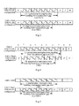
- Fig.3 is a schematic diagram of determining uplink transmission interruption time over each of the Cell 1 and the Cell 2.
- the uplink transmission interruption time resulting from the measurement gap over the Cell 1 is different from that over the Cell 2.
- the uplink transmission interruption time resulting from the measurement gap can be determined based upon the UE.
- a method for determining the uplink transmission interruption time resulting from the measurement gap based upon the UE is to take the union set of the uplink transmission interruption time of all the cells aggregated by the UE as the uplink transmission interruption time of each cell aggregated by the UE.
- Sub-frames denoted by diagonals in Fig.3 relate to the uplink transmission interruption time resulting from the measurement gap over the Cell 1.
- the UE is not allowed for transmission of a PUSCH and/or a PUCCH (including a CQI/PMI/RI/SR/HARQ feedback) and/or an SRS and/or a PRACH, etc., during the uplink transmission interruption time. Moreover if there is a UL grant in the uplink transmission interruption time of some cell, then the UE can process the UL grant over the cell.
- the embodiment above has been described by way of an example where the union set of the uplink transmission interruption time of all the cells aggregated by the UE is taken as the uplink transmission interruption time of each cell aggregated by the UE.
- the method for determining the uplink transmission interruption time resulting from the measurement gap based upon the UE can alternatively be modified to take the intersection set of the uplink transmission interruption time of all the cells aggregated by the UE as the uplink transmission interruption time of each cell aggregated by the UE, and in this case, the UE can be required to be provided with at least two transceivers.
- the uplink transmission interruption time resulting from the measurement gap is determined based upon the UE.
- the uplink transmission interruption time of each cell is a union set of the uplink transmission interruption time over all the cells aggregated by the UE, and the TDD cell adopts a dynamic UL/DL configuration.
- the sub-frames 1 and 4 of the Cell 1 are fixed DL sub-frames
- the sub-frame 2 is a fixed UL sub-frame
- the sub-frames 0 and 3 are dynamic sub-frames.
- the Cell 2 adopts the fixed third TDD UL/DL configuration.
- the UE operating in the current band combination needs the measurement gap when measuring at a frequency f, so the base station device needs to configure the measurement gap when configuring the UE to measure at the frequency f.
- the uplink transmission interruption time over each of the Cell 1 and the Cell 2 can be determined respectively according to the mechanism of determining the uplink transmission interruption time resulting from the measurement gap.
- Fig.4 is a schematic diagram of determining the uplink transmission interruption time over each of Cell 1 and Cell 2. Since the Cell 2 adopts the fixed TDD UL/DL configuration, there is a fixed uplink transmission interruption time resulting from the measurement gap. For the Cell 1, however, if the sub-frames 0, 3, 5 and 8 are sub-frames of which transmission directions can be determined dynamically, then the sub-frame 0 and the sub-frame 8 are considered as downlink sub-frames because a PDCCH is received therein, and the sub-frame 3 and the sub-frame 5 are considered as uplink sub-frames because no PDCCH is received therein.
- a downlink sub-frame is prior to the measurement gap and a UL sub-frame is subsequent to the measurement gap, so the uplink transmission interruption time resulting from the measurement gap over the Cell 1 is longer than the uplink transmission interruption time resulting from the measurement gap over the cell 2 by 1ms.
- the uplink transmission interruption time resulting from the measurement gap over the Cell 1 is different from that over the Cell 2.
- the uplink transmission interruption time resulting from the measurement gap can be determined based upon the UE.
- a method for determining the uplink transmission interruption time resulting from the measurement gap based upon the UE is to take a union set of uplink transmission interruption time of all the cells aggregated by the UE as the uplink transmission interruption time of each cell aggregated by the UE.
- Sub-frames denoted by diagonals in Fig.4 relate to the uplink transmission interruption time resulting from the measurement gap over the Cell 1.
- the UE is not allowed for transmission of a PUSCH and/or a PUCCH (including a CQI/PMI/RI/SR/HARQ feedback) and/or an SRS and/or a PRACH, etc., during the uplink transmission interruption time. Moreover if there is a UL grant in the uplink transmission interruption time of some cell, then the UE can process the UL grant over the cell.
- the embodiment above has been described by way of an example where the union set of the uplink transmission interruption time of all the cells aggregated by the UE is taken as the uplink transmission interruption time of each cell aggregated by the UE.
- the method for determining the uplink transmission interruption time resulting from the measurement gap based upon the UE can alternatively be modified to take the intersection set of the uplink transmission interruption time of all the cells aggregated by the UE as the uplink transmission interruption time of each cell aggregated by the UE, and in this case, the UE can be required to be provided with at least two transceivers.
- the uplink transmission interruption time resulting from the measurement gap is determined based upon the set of same duplex configurations (and also the same UL/DL configurations for TDD).
- the Cell 1 and the Cell 2 use the FDD and the third TDD UL/DL configuration respectively.
- the UE needs the measurement gap when measuring at a frequency f when both the Cell 1 and the Cell 2 are aggregated by the UE.
- the base station device needs to configure the measurement gap when configuring the UE to measure at the frequency f.
- the uplink transmission interruption time over each of the Cell 1 and the Cell 2 can be determined respectively in the mechanism of determining the uplink transmission interruption time resulting from the measurement gap.
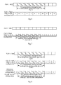
- Fig.5 is a schematic diagram of determining the uplink transmission interruption time over each of the Cell 1 and the Cell 2.
- the uplink transmission interruption time resulting from the measurement gap over the Cell 1 is different from that over the Cell 2.
- the transmission of PUCCH/PUSCH/SRS/PRACH over the Cell 1 is not allowed to be performed in the sub-frames denoted by diagonals over the Cell 1
- the transmission of PUCCH/PUSCH/SRS/PRACH over the Cell 2 is not allowed to be performed in the sub-frames denoted by diagonals over the Cell 2.
- the factor of a plurality of transceivers is taken into account, e.g., an implicitly reported correspondence relationship between bands and transceivers.
- the Cell 1 and the Cell 2 use the FDD and the third TDD UL/DL configuration respectively, and the Cell 1 and the Cell 2 use separate transceivers respectively.
- the UE reports the UE capability
- the UE reports the correspondence relationship between bands and transceivers to the base station device, for example, the band 1 corresponding to the Cell 1 relates to the transceiver 1, and the band 2 corresponding to the Cell 2 relates to the transceiver 2.
- the base station device needs to take into account the UE capability reported by the UE when configuring measurements at different frequencies or in different systems. If the reported UE capability indicates that the UE in the current operating band combination needs the measurement gap when measuring at a frequency f, then the base station device needs to configure the measurement gap when configuring the UE to measure at the frequency f. If the UE is provided with a plurality of transceivers and supports the full-duplex mode, then although the base station device configures the measurement gap, the UE only needs to tune one of the transceivers for measurement at different frequencies or in different systems, that is, the UE only needs to interrupt uplink/downlink data transmission of the transceiver without any influence upon uplink/downlink data transmission of the other transceivers.
- Fig.6 is a schematic diagram of determining the uplink transmission interruption time over the Cell 1.
- the base station device and the UE can prescribe a specific one of the plurality of transceivers with transmission thereof to be interrupted, for example, the transceiver supporting the lowest or the highest frequency is interrupted, or the base station device can configure a transceiver to be interrupted in explicit signaling (RRC/MACK/L1).
- the factor of a plurality of transceivers is taken into account, e.g., an implicitly reported correspondence relationship between bands and transceivers.
- the Cell 1 and the Cell 2 are located in the band 1 and the band 2 respectively, and use the FDD and the third TDD UL/DL configuration respectively.
- the UE reports no need of the measurement gap as reporting the measurement capability at a frequency f for the band 1, and reports no need of the measurement gap as reporting the measurement capability at the frequency f for the band 2, but reports a need of the measurement gap as reporting the measurement capability at the frequency f for the combination of the band 1 and the band 2.
- the base station device can determine implicitly from the reported UE capability the correspondence relationship between bands and transceivers, i.e., different transceivers respectively for the Cell 1 and the Cell 2.
- the base station device needs take into account the UE capability reported by the UE when configuring measurements at different frequencies or in different systems. If the reported UE capability indicates that the UE in the current operating band combination needs the measurement gap when measuring at the frequency f, then the base station device needs to configure the measurement gap when configuring the UE to measure at the frequency f. If the UE is provided with a plurality of transceivers and supports the full-duplex mode, then although the base station device configures the measurement gap, the UE only needs to tune one of the transceivers for measurement at different frequencies or in different systems, that is, the UE only needs to interrupt uplink/downlink data transmission of the transceiver without any influence upon uplink/downlink data transmission of the other transceivers.
- Fig.7 is a schematic diagram of determining the uplink transmission interruption time over the Cell 2.
- the base station device and the UE can prescribe a specific one of the plurality of transceivers with transmission thereof to be interrupted, for example, the transceiver supporting the lowest or the highest frequency is interrupted, or the base station device can configure a transceiver or a cell to be interrupted in explicit signaling (RRC/MACK/L1).
- the uplink transmission interruption time resulting from the measurement gap is determined based upon the UE, where the reference TDD UL/DL configuration is used for determining the uplink transmission interruption time resulting from the measurement gap.
- the base station device needs to configure the measurement gap when configuring the UE to measure at the frequency f.
- the uplink transmission interruption time resulting from the measurement gap is determined according to the reference TDD UL/DL configuration (e.g., the second TDD UL/DL configuration) and taken as the uplink transmission interruption time over each of the Cell 1 and the Cell 2, as illustrated in Fig. 8 .
- the reference TDD UL/DL configuration e.g., the second TDD UL/DL configuration
- the UE is not allowed for transmission of a PUSCH and/or a PUCCH (including a CQI/PMI/RI/SR/HARQ feedback) and/or an SRS and/or a PRACH, etc., during the uplink transmission interruption time. Moreover, if there is a UL grant in the uplink transmission interruption time of some cell, then the UE can process the UL grant over the cell.
- an embodiment of the invention further provides a UE.
- the UE includes:
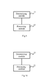
- a determining module 11 configured to determine uplink transmission interruption time of each cell aggregated by the UE.
- a processing module 12 configured to stop, during the uplink transmission interruption time of each cell aggregated by the UE, uplink transmission of the cell.
- the determining module 11 is particularly configured to determine uplink transmission interruption time corresponding to all cells aggregated by the UE as the uplink transmission interruption time of each cell; or to determine the uplink transmission interruption time respectively for each cell aggregated by the UE; or to determine a transceiver required to perform measurements and aggregated cells served by the transceiver, to determine uplink transmission interruption time of the respective aggregated cells served by the transceiver, and to determine uplink transmission interruption time of aggregated cells served by other transceivers of the UE to be 0.
- the determining module 11 is configured to determine uplink transmission interruption time resulting from a measurement gap over each cell aggregated by the UE according to a duplex mode and/or TDD UL/DL configuration of the each cell, and to determine a union set or an intersection set of the uplink transmission interruption time over all cells as the uplink transmission interruption time of the each cell; or to determine the uplink transmission interruption time of each cell to be a Measurement Gap Length (MGL) plus a specified value; or to determine uplink transmission interruption time resulting from a measurement gap according to a reference duplex mode and/or TDD UL/DL configuration, and to take the uplink transmission interruption time as the uplink transmission interruption time of the each cell.
- MNL Measurement Gap Length
- the determining module 11 is configured to determine the uplink transmission interruption time respectively for each cell based upon a set of duplex configurations to which the each cell belongs, where the set of duplex configurations includes at least one aggregated cell, and when the set of duplex configurations includes a plurality of cells, the plurality of cells have a same duplex mode and/or TDD UL/DL configuration.
- the determining module 11 is configured to determine uplink transmission interruption time according to a duplex mode and/or TDD UL/DL configuration in the set of duplex configurations, and to take the uplink transmission interruption time as the uplink transmission interruption time of each cell in the set of duplex configurations; or to determine uplink transmission interruption time according to a reference duplex mode and/or TDD UL/DL configuration in the set of duplex configurations, and to take the uplink transmission interruption time as the uplink transmission interruption time of each cell in the set of duplex configurations.
- the determining module 11 is configured to determine a transceiver at a highest frequency as the transceiver required to perform the measurements; or to determine a transceiver at a lowest frequency as the transceiver required to perform the measurements; or to receive explicit configuration information from a base station device to indicate a band corresponding to the transceiver required to perform the measurements, and to determine a transceiver corresponding to the band as the transceiver required to perform the measurements.
- the determining module 11 is configured to determine uplink transmission interruption time resulting from a measurement gap over each aggregated cell served by the transceiver according to a duplex mode and/or TDD UL/DL configuration of the each cell, and to take the determined uplink transmission interruption time as the uplink transmission interruption time corresponding to the each cell; or
- the reference duplex mode and/or TDD UL/DL configuration particularly includes:
- a duplex mode and/or a TDD UL/DL configuration of a PCell A duplex mode and/or a TDD UL/DL configuration of a PCell
- a duplex mode and/or a TDD UL/DL configuration configured by an OAM or
- a duplex mode and/or a TDD UL/DL configuration notified by the base station device to the UE via an explicit signaling is notified by the base station device to the UE via an explicit signaling.
- the processing module 12 is particularly configured to stop, during the uplink transmission interruption time of each cell aggregated by the UE, transmitting one or any combination of the following information over the cell: a PUSCH, a PUCCH, a PRACH and an SRS.
- the PUCCH includes one or any combination of the following information: a CQI, a PMI, an RI, an SR and an HARQ feedback.
- the cells aggregated by the UE use different duplex modes and/or different TDD UL/DL configurations.
- the respective modules of the device according to the invention can be integrated or can be deployed separately.
- the modules above can be combined into one module or can be further divided into a plurality of sub-modules.
- an embodiment of the invention further provides a base station device, and as illustrated in Fig. 10 , the base station device includes:
- a determining module 21 configured to determine uplink transmission interruption time of each cell aggregated by a UE.
- a processing module 22 configured to stop sending uplink transmission scheduling information during the uplink transmission interruption time of each cell aggregated by the UE to the UE over the cell.
- the determining module 21 is particularly configured to determine uplink transmission interruption time corresponding to all cells aggregated by the UE as the uplink transmission interruption time of each cell; or to determine the uplink transmission interruption time respectively for each cell aggregated by the UE; or to determine a transceiver required to perform measurements of the UE and aggregated cells served by the transceiver, to determine uplink transmission interruption time of the respective aggregated cells served by the transceiver, and to determine uplink transmission interruption time of aggregated cells served by other transceivers of the UE to be 0.
- the determining module 21 is configured to determine uplink transmission interruption time resulting from a measurement gap over each cell aggregated by the UE according to a duplex mode and/or TDD UL/DL configuration of the each cell, and to determine a union set or an intersection set of the uplink transmission interruption time over all cells as the uplink transmission interruption time of the each cell; or to determine the uplink transmission interruption time of each cell to be a Measurement Gap Length (MGL) plus a specified value; or to determine uplink transmission interruption time resulting from a measurement gap according to a reference duplex mode and/or TDD UL/DL configuration, and to take the uplink transmission interruption time as the uplink transmission interruption time of the each cell.
- MNL Measurement Gap Length
- the determining module 21 is configured to determine the uplink transmission interruption time respectively for each cell aggregated by the UE based upon a set of duplex configurations to which the each cell belongs, where the set of duplex configurations includes at least one aggregated cell, and when the set of duplex configurations includes a plurality of cells, the plurality of cells have a same duplex mode and/or TDD UL/DL configuration.
- the determining module 21 is configured to determine uplink transmission interruption time according to a duplex mode and/or TDD UL/DL configuration in the set of duplex configurations, and to take the uplink transmission interruption time as the uplink transmission interruption time of each cell in the set of duplex configurations; or to determine uplink transmission interruption time according to a reference duplex mode and/or TDD UL/DL configuration in the set of duplex configurations, and to take the uplink transmission interruption time as the uplink transmission interruption time of each cell in the set of duplex configurations.
- the determining module 21 is configured to determine a transceiver at a highest frequency as the transceiver required to perform the measurements of the UE; or to determine a transceiver at a lowest frequency as the transceiver required to perform the measurements of the UE; or to obtain a correspondence relationship between bands supported by the UE and transceivers, to determine one of a plurality of transceivers as the transceiver required to perform the measurements of the UE, and to notify the UE of information about a band corresponding to the transceiver required to perform the measurements via explicit configuration information.
- the determining module 21 is further configured to obtain the correspondence relationship between bands supported by the UE and transceivers from a correspondence relationship between bands and transceivers reported in the UE capability; or to obtain the correspondence relationship between bands supported by the UE and transceivers from a measurement gap capability reported based upon a band combination in the UE capability.
- the determining module 21 is further configured to determine uplink transmission interruption time resulting from a measurement gap over each aggregated cell served by the transceiver according to a duplex mode and/or TDD UL/DL configuration of the each cell, and to take the determined uplink transmission interruption time as the uplink transmission interruption time corresponding to the each cell; or
- the reference duplex mode and/or TDD UL/DL configuration particularly includes:
- a duplex mode and/or a TDD UL/DL configuration configured by an OAM and
- a duplex mode and/or a TDD UL/DL configuration determined and notified by the base station device to the UE via an explicit signaling.
- the cells aggregated by the UE use different duplex modes and/or different TDD UL/DL configurations.
- the respective modules of the device according to the invention can be integrated or can be deployed separately.
- the modules above can be combined into one module or can be further divided into a plurality of sub-modules.
- modules in the devices of the embodiments can be distributed in the devices of the embodiments as described in the embodiments or located in one or more devices different from those of the embodiments given corresponding variations.
- the modules of the foregoing embodiments can be integrated together or deployed separately or can be combined into one module or further subdivided into a plurality of sub-modules.
Landscapes
- Engineering & Computer Science (AREA)
- Signal Processing (AREA)
- Computer Networks & Wireless Communication (AREA)
- Environmental & Geological Engineering (AREA)
- Databases & Information Systems (AREA)
- Mobile Radio Communication Systems (AREA)
Description
- The present invention relates to the field of communications and particularly to a method and a device for determining uplink transmission interruption time.
- Time Division Duplex (TDD) uplink/downlink (UL/DL) configurations are as depicted in Table 1. Seven kinds of TDD UL/DL configurations are defined for a TDD system in the physical layer standard, where D represents a DL sub-frame, U represents a UL sub-frame, and S represents a special sub-frame of the TDD system.
Table 1 TDD UL/DL configurations TDD UL/DL configuration No. Serial number of sub-frame 0 1 2 3 4 5 6 7 8 9 0 D S U U U D S U U U 1 D S U U D D S U U D 2 D S U D D D S U D D 3 D S U U U D D D D D 4 D S U U D D D D D D 5 D S U D D D D D D D 6 D S U U U D S U U D - Typically the TD UL/DL configuration of each cell is determined and can be notified to a User Equipment (UE) in a broadcast message. However in order to utilize resources more flexibly, a dynamic TDD UL/DL configuration is supported in the Long Tem Evolution (LTE) system, that is, transmission directions in a part or all of sub-frames in a radio frame are determined as scheduled. For example, if some sub-frame has no UL scheduling signaling or is not configured with a Physical Uplink Control Channel (PUCCH)/Sounding Reference Signal (SRS), then it can be considered as a downlink sub-frame; otherwise, it can be considered as an uplink sub-frame.
- The Carrier Aggregation (CA) technology has been proposed in the prior art. As compared with the LTE system, the peak rates in the Long Term Evolution-Advanced (LTE-A) are improved significantly, where 1Gbps in the downlink and 500Mbps in the uplink are required. The LTE-A system is required to be well compatible with the LTE system. The carrier aggregation technology has been introduced to the LTE-A system to thereby accommodate the improved peak rates, compatibility with the LTE system and full use of spectrum resources as needed. With the CA technology, a User Equipment (UE) can operate concurrently over a plurality of cells, where these cells can be consecutive or inconsecutive in frequency, and bandwidths of the respective cells may be the same or different. There is a limited bandwidth up to 20MHz of each cell for compatibility with the LTE system, and the number of cells that can be aggregated by one UE is typically up to 5 at present.
- In the CA system, cells configured by an evolved Node B (eNB) for the UE are referred to as serving cells. All the functions of the different serving cells may not be the same, so the serving cells are further categorized in the LTE-A system as follows: a Primary Cell (PCell) and a Secondary Cell (SCell), where only one of the plurality of cells aggregated by the UE is defined as the PCell. The PCell is selected by the eNB and configured to the UE in Radio Resource Control (RRC) signaling, and only the PCell is configured with a PUCCH. All the cells except the PCell aggregated by the UE are SCells.
- The concept of the measurement gap has been proposed in the prior art. In order to perform a cell handover between different frequencies or different systems, the LTE system needs to configure the UE to stop receiving and sending data over the current operating band for a period of time and to tune a transceiver to measure the channel quality at a different frequency or in a different system cell, where the period of time is referred to as the measurement gap. Moreover in the LTE system, patterns of the measurement gap are as depicted in Table 2.
Table 2 Gap pattern configurations supported by UE Gap pattern Measurement Gap Length (MGL) (in ms) Repetitive periodicity of measurement gap (in ms) Shortest measurement period (in ms) for different frequency or different system in 480 ms 0 6 40 60 1 6 80 30 - It shall be noted that in the LTE-A R10, whether the UE needs the measurement gap when measuring some frequency point depends upon the UE capability. The UE signals the UE capability to the eNB in a UE capability report, where a measurement capability in the UE capability report signaling is reported per band combination, that is, a report is made on whether the UE operating in some band combination needs a measurement gap when measuring another band. Since the UE needs to tune the transceiver in the measurement gap to measure at a specified different frequency or frequency of a different system, the uplink/downlink transmission in the current serving cell needs to be interrupted.
- In the prior art, systems of the LTE-A R10 and earlier only support aggregation of cells in the same duplex mode or the same TDD UL/DL configuration by the UE, so the uplink transmission interruption time resulting from the measurement gap is the same for all the cells aggregated by the UE, and once uplink transmission interruption resulting from the measurement gap occurs, the UE can stop uplink transmission over all the cells without distinguishing one cell from another.
- The inventors have identified, during making of the technical solution of the invention, at least the following problems in the prior art:
- In systems of the LTE-A R11 and later, cells in different duplex modes or different TDD UL/DL configurations are allowed to be aggregated by the UE, so the uplink transmission interruption time resulting from the measurement gap may not be the same for all the cells aggregated by the UE. In the prior art, there is no solution how the UE shall stop uplink transmission over the respective cells when the uplink transmission interruption resulting from the measurement gap occurs.
- Embodiments of the invention provide a method and a device for determining uplink transmission interruption time so as to determine the uplink transmission interruption time resulting from a measurement gap when cells in different duplex modes or different TDD UL/DL configurations are aggregated by a UE.
- In order to attain the object above, an embodiment of the invention provides a method for determining uplink transmission interruption time, the method including:
- a UE determining uplink transmission interruption time of each cell aggregated by the UE; and
- the UE stopping, during the uplink transmission interruption time of each cell aggregated by the UE, uplink transmission of the cell.
- An embodiment of the invention further provides another method for determining uplink transmission interruption time, the method including:
- a base station device determining uplink transmission interruption time of each cell aggregated by a UE; and
- the base station device stopping sending uplink transmission scheduling information during the uplink transmission interruption time of each cell aggregated by the UE to the UE over the cell.
- An embodiment of the invention further provides a UE including:
- a determining module configured to determine uplink transmission interruption time of each cell aggregated by the UE; and
- a processing module configured to stop, during the uplink transmission interruption time of each cell aggregated by the UE, uplink transmission of the cell.
- An embodiment of the invention further provides a base station device including:
- a determining module configured to determine uplink transmission interruption time of each cell aggregated by a UE; and
- a processing module configured to stop sending uplink transmission scheduling information during the uplink transmission interruption time of each cell aggregated by the UE to the UE over the cell.
- As can be apparent from the technical solution above, the uplink transmission interruption time of each cell aggregated by a UE can be determined to thereby determine definitively the uplink transmission interruption time resulting from the measurement gap so that the UE can know how to stop uplink transmission over the respective cells.
- In order to illustrate the technical solution of the invention more clearly, the drawings required to be used in the description of the embodiments will be briefly introduced below, and apparently the drawings to be described below are merely illustrative of some of the embodiments of the invention, and those ordinarily skilled in the art can derive other drawings from these drawings without any inventive effort.
-
Fig.1 is a schematic flow chart of determining, by a UE, uplink transmission interruption time according to a first embodiment of the invention; -
Fig.2 is a schematic flow chart of determining, by a base station device, uplink transmission interruption time according to the first embodiment of the invention; -
Fig.3 is a schematic diagram of determining uplink transmission interruption time over each ofCell 1 andCell 2 according to a second embodiment of the invention; -
Fig.4 is a schematic diagram of determining uplink transmission interruption time over each ofCell 1 andCell 2 according to a third embodiment of the invention; -
Fig.5 is a schematic diagram of determining uplink transmission interruption time over each ofCell 1 andCell 2 according to a fourth embodiment of the invention; -
Fig.6 is a schematic diagram of determining uplink transmission interruption time overCell 1 according to a fifth embodiment of the invention; -
Fig.7 is a schematic diagram of determining uplink transmission interruption time overCell 2 according to a sixth embodiment of the invention; -
Fig.8 is a schematic diagram of determining uplink transmission interruption time over each ofCell 1 andCell 2 according to a seventh embodiment of the invention; -
Fig.9 is a schematic structural diagram of a user equipment according to an eighth embodiment of the invention; and -
Fig.10 is a schematic structural diagram of a base station device according to a ninth embodiment of the invention. - The technical solution according to the embodiments of the invention will be described below clearly and fully with reference to the drawings. Apparently the described embodiments are only a part, but not all, of the embodiments of the invention. Based upon the embodiments of the invention, all the other embodiments derived by those ordinarily skilled in the art without any inventive effort shall fall into the scope of the invention.
- The first embodiment of the invention provides a method for determining uplink transmission interruption time (i.e., uplink transmission interruption time resulting from a measurement gap), which can be applicable to system of the LTE-A R11 and later and in which cells in different duplex modes or different TDD UL/DL configurations are allowed to be aggregated by a UE. The method can include a process of determining, by a UE, uplink transmission interruption time and a process of determining, by a base station device, uplink transmission interruption time.
-
Fig.1 is a flow chart of determining, by a UE, uplink transmission interruption time. As illustrated inFig.1 , the method includes the following operations. - Operation 101: the UE determines uplink transmission interruption time of each cell aggregated by the UE.
- In an embodiment of the invention, the UE determines the uplink transmission interruption time of each cell aggregated by the UE in the following three approaches without any limitation thereto.
- In a first approach, the uplink transmission interruption time resulting from the measurement gap is determined based upon the UE.
- In this first approach, the UE determines uplink transmission interruption time corresponding to all the cells aggregated by the UE as the uplink transmission interruption time of each cell. For example, when three cells are aggregated by the UE, these three cells correspond to the same uplink transmission interruption time, so the uplink transmission interruption time is determined as the uplink transmission interruption time of each cell.
- Particularly the UE determines the uplink transmission interruption time corresponding to all the cells aggregated by the UE as the uplink transmission interruption time of each cell as follows:
- The UE determines uplink transmission interruption time resulting from the measurement gap over each cell aggregated by the UE according to the duplex mode and/or TDD UL/DL configuration of the each cell, and determines a union set or an intersection set of the uplink transmission interruption time over all cells as the uplink transmission interruption time of the each cell; or
- When the UE and a base station device prescribe the uplink transmission interruption time resulting from the measurement gap to be (MGL + a specified value) ms, the UE determines the uplink transmission interruption time of the each cell to be (MGL + the specified value) ms, for example, the specified value is 1ms; or
- The UE determines uplink transmission interruption time resulting from the measurement gap according to a reference duplex mode and/or TDD UL/DL configuration and takes the uplink transmission interruption time as the uplink transmission interruption time of each cell, where the reference duplex mode and/or TDD UL/DL configuration is any one of the following duplex modes and/or TDD UL/DL configurations:
- 1) A duplex mode and/or a TDD UL/DL configuration of a PCell;
- 2) A duplex mode and/or a TDD UL/DL configuration prescribed by the base station device and the UE;
- 3) A duplex mode and/or a TDD UL/DL configuration configured by an Operation Administration and Maintenance (OAM) entity; and
- 4) A duplex mode and/or a TDD UL/DL configuration notified by the base station device to the UE via an explicit signaling.
- The explicit signaling can be RRC signaling, MAC signaling or physical layer signaling.
- In an embodiment of the invention, in the processes of determining the uplink transmission interruption time of each cell according to the duplex mode and/or the TDD UL/DL configuration of each cell and of determining the uplink transmission interruption time of each cell according to the reference duplex mode and/or TDD UL/DL configuration, the uplink transmission interruption time resulting from the measurement gap is associated with the duplex mode(s) and/or the TDD UL/DL configuration(s). For FDD, the uplink transmission interruption time resulting from the measurement gap is MGL plus the first sub-frame subsequent to MGL. For TDD, if the sub-frame prior to the measurement gap is a DL sub-frame and the first sub-frame subsequent to the measurement gap is a UL sub-frame, then the uplink transmission interruption time resulting from the measurement gap is MGL plus the first sub-frame subsequent to MGL. In other situations, the uplink transmission interruption time resulting from the measurement gap is MGL.
- It shall be noted that this approach, in which the uplink transmission interruption time resulting from the measurement gap is determined based upon the UE, can be applicable to full-duplex and half-duplex UEs.
- In a second approach, the uplink transmission interruption time resulting from the measurement gap is determined based upon a set of same duplex configurations.
- In this second approach, the UE determines the uplink transmission interruption time respectively for each cell based upon a set of duplex configurations to which the each cell belongs, where the set of duplex configurations includes at least one aggregated cell, and when the set of duplex configurations includes a plurality of cells, the plurality of cells have the same duplex mode and/or TDD UL/DL configuration.
- When each set of same duplex configurations includes one cell, which indicates that the respective cells aggregated by the UE adopt different duplex modes and/or TDD UL/DL configurations, the event that the UE determines the uplink transmission interruption time respectively for each cell based upon the set of duplex configurations to which the each cell belongs is equivalent to that the UE determines the uplink transmission interruption time corresponding to each cell aggregated by the UE. That is, the uplink transmission interruption time resulting from the measurement gap is determined respectively for each cell according to its duplex mode. Its TDD UL/DL configuration needs to be further taken into account for TDD. For example, when three cells are aggregated by the UE and these three cells adopt different duplex modes and/or TDD UL/DL configurations, each of the three cells corresponds respectively to one uplink transmission interruption time.
- Furthermore, the UE determines the uplink transmission interruption time respectively for each cell based upon the set of duplex configurations to which the each cell belongs as follows: the UE determines uplink transmission interruption time according to a duplex mode and/or TDD UL/DL configuration in the set of duplex configurations, and takes the uplink transmission interruption time as the uplink transmission interruption time of each cell in the set of duplex configurations; or, the UE determines uplink transmission interruption time according to a reference duplex mode and/or TDD UL/DL configuration in the set of duplex configurations, and takes the uplink transmission interruption time as the uplink transmission interruption time of each cell in the set of duplex configurations, where the reference duplex mode and/or TDD UL/DL configuration is any one of the following duplex modes and/or TDD UL/DL configurations:
- 1) A duplex mode and/or a TDD UL/DL configuration of a PCell;
- 2) A duplex mode and/or a TDD UL/DL configuration prescribed by the base station device and the UE;
- 3) A duplex mode and/or a TDD UL/DL configuration configured by an OAM entity; and
- 4) A duplex mode and/or a TDD UL/DL configuration notified by the base station device to the UE via an explicit signaling.
- The explicit signaling can be RRC signaling, MAC signaling or physical layer signaling.
- In an embodiment of the invention, in the process in which the UE determines the uplink transmission interruption time corresponding to each cell in the set of duplex configurations according to the duplex mode and/or the TDD UL/DL configuration in the set of duplex configurations or according to the reference duplex mode and/or TDD UL/DL configuration in the set of duplex configurations, the uplink transmission interruption time resulting from the measurement gap is associated with the duplex mode(s) and/or the TDD UL/DL configuration(s). For FDD, the uplink transmission interruption time resulting from the measurement gap is MGL plus the first sub-frame subsequent to MGL. For TDD, if the sub-frame prior to the measurement gap is a DL sub-frame and the first sub-frame subsequent to the measurement gap is a UL sub-frame, then the uplink transmission interruption time resulting from the measurement gap is MGL plus the first sub-frame subsequent to MGL. In other situations, the uplink transmission interruption time resulting from the measurement gap is MGL.
- It shall be noted that this approach of determining the uplink transmission interruption time resulting from the measurement gap based upon the cell or the set of same duplex configurations can be applicable to the full-duplex UE.
- In a third approach, the uplink transmission interruption time resulting from the measurement gap is determined based upon the transceiver.
- It is only necessary to tune one of transceivers for different frequencies/different systems without interrupting transmission of uplink/downlink data in cells supported by the other transceivers, so in the third approach, the UE can determine the transceiver required to perform measurements and the aggregated cells served by the transceiver and determine the uplink transmission interruption time respectively for each aggregated cell served by the transceiver, and determine uplink transmission interruption time of aggregated cells served by other transceivers of the UE to be 0, that is, it is not necessary to determine the uplink transmission interruption time for the aggregated cells served by the other transceivers.
- Furthermore, the process of determining, by the UE, the transceiver required to perform measurements (i.e., a specific transceiver to be tuned) includes: when the UE and the base station device prescribe to tune the transceiver supporting the highest frequency, the UE determines the transceiver at the highest frequency as the transceiver required to perform measurements; or when the UE and the base station device prescribe to tune the transceiver supporting the lowest frequency, the UE determines the transceiver at the lowest frequency as the transceiver required to perform measurements; or when the base station device explicitly configures a transceiver to be tuned, the UE receives the explicit configuration information from the base station device to indicate the band corresponding to the transceiver required to perform measurements and determines the transceiver corresponding to the band as the transceiver required to perform measurements.
- In an embodiment of the invention, the UE determines the uplink transmission interruption time of each aggregated cell served by the transceiver particularly as follows:
- The UE determines the uplink transmission interruption time resulting from the measurement gap over each of the aggregated cells served by the transceiver according to the duplex mode and/or TDD UL/DL configuration of each cell, and takes the determined uplink transmission interruption time as the uplink transmission interruption time corresponding to each cell; or
- The UE determines the uplink transmission interruption time resulting from the measurement gap over each of the aggregated cells served by the transceiver according to the duplex mode and/or TDD UL/DL configuration of each cell, and takes the union set of the uplink transmission interruption time over all the cells as the uplink transmission interruption time of each cell; or
- The UE determines the uplink transmission interruption time resulting from the measurement gap according to the reference duplex mode and/or TDD UL/DL configuration, and takes the uplink transmission interruption time as the uplink transmission interruption time of each aggregated cell served by the transceiver, where the reference duplex mode and/or TDD UL/DL configuration is any one of the following duplex modes and/or TDD UL/DL configurations:
- 1) A duplex mode and/or a TDD UL/DL configuration of a PCell;
- 2) A duplex mode and/or a TDD UL/DL configuration prescribed by the base station device and the UE;
- 3) A duplex mode and/or a TDD UL/DL configuration configured by an OAM entity; and
- 4) A duplex mode and/or a TDD UL/DL configuration notified by the base station device to the UE via an explicit signaling.
- The explicit signaling can be RRC signaling, MAC signaling or physical layer signaling.
- In an embodiment of the invention, in the process in which the UE determines the uplink transmission interruption time of each of the aggregated cells served by the transceiver, the uplink transmission interruption time resulting from the measurement gap is associated with the duplex modes and the TDD UL/DL configurations of the cells corresponding to the transceiver or the reference duplex mode and TDD UL/DL configuration used by the cells corresponding to the transceiver. For FDD, the uplink transmission interruption time resulting from the measurement gap is MGL plus the first sub-frame subsequent to MGL. For TDD, if the sub-frame prior to the measurement gap is a DL sub-frame and the first sub-frame subsequent to the measurement gap is a UL sub-frame, then the uplink transmission interruption time resulting from the measurement gap is MGL plus the first sub-frame subsequent to MGL. In other situations, the uplink transmission interruption time resulting from the measurement gap is MGL.
- It shall be noted that this approach of determining the uplink transmission interruption time resulting from the measurement gap based upon the transceiver can be applicable to the UE with a plurality of transceivers and supporting the full-duplex mode.
- Operation 102: the UE stops, during the uplink transmission interruption time of each cell aggregated by the UE, uplink transmission of the cell. For the first approach above, the UE stops uplink transmission of all the cells during the determined uplink transmission interruption time without adopting different uplink transmission processes for different cells. For the second approach above, during the uplink transmission interruption time, the UE stops uplink transmission of the cells corresponding to the determined uplink transmission interruption time, which is required to process uplink transmission differently from one cell to another. For the third approach above, during the determined uplink transmission interruption time, the UE stops uplink transmission of the cells corresponding to the determined transceiver, which is required to adopt different uplink transmission processes for different cells.
- In an embodiment of the invention, if the uplink transmission interruption time resulting from the measurement gap is determined based upon the UE, then during the uplink transmission interruption time determined based upon the measurement gap, the UE is not allowed for performing any uplink transmission but can process the UL grant. Thus during the uplink transmission interruption time of the respective cells aggregated by the UE, the UE stops uplink transmission of the cells as follows: during the uplink transmission interruption time of each cell aggregated by the UE, the UE stops transmitting one or any combination of the following information over the cell: a Physical Uplink Shared Channel (PUSCH), a PUCCH, a Physical Random Access Channel (PRACH) and a Sounding Reference Signal (SRS).
- Furthermore, the PUCCH includes one or any combination of the following information: a Channel Quality Indicator (CQI), a Pre-coding Matrix Indicator (PMI), a Rank Indication (RI), a Scheduling Request (SR) and a Hybrid Automatic Repeat Request (HARQ) feedback.
- In an embodiment of the invention, different duplex modes and/or different TDD UL/DL configurations can apply to the cells aggregated by the UE. For example, different duplex modes and/or different TDD UL/DL configurations can apply to at least two cells.
-
Fig.2 is a flow chart of determining, by a base station device, uplink transmission interruption time. As illustrated inFig.2 , the method includes the following operations: - Operation 201: the base station device determines uplink transmission interruption time of each cell aggregated by a UE.
- In an embodiment of the invention, the base station device determines the uplink transmission interruption time of each cell aggregated by the UE in the following three approaches without any limitation thereto.
- In a first approach, the uplink transmission interruption time resulting from the measurement gap is determined based upon the UE.
- In this first approach, the base station device determines the uplink transmission interruption time corresponding to all the cells aggregated by the UE as the uplink transmission interruption time of each cell. For example, when three cells are aggregated by the UE, these three cells correspond to the same uplink transmission interruption time.
- Particularly the base station device determines the uplink transmission interruption time corresponding to all the cells aggregated by the UE as the uplink transmission interruption time of each cell as follows:
- The base station device determines the uplink transmission interruption time resulting from the measurement gap over each cell aggregated by the UE according to the duplex mode and/or TDD UL/DL configuration of the each cell, and determines a union set or an intersection set of the uplink transmission interruption time over all cells as the uplink transmission interruption time of the each cell; or
- When the UE and the base station device prescribe the uplink transmission interruption time resulting from the measurement gap to be (MGL + a specified value) ms, the base station device determines the uplink transmission interruption time of each cell to be (MGL + the specified value) ms, for example, the specified value is 1ms; or
- The base station device determines the uplink transmission interruption time resulting from the measurement gap according to the reference duplex mode and/or TDD UL/DL configuration and takes the uplink transmission interruption time as the uplink transmission interruption time of each cell, where the reference duplex mode and/or TDD UL/DL configuration is any one of the following duplex modes and/or TDD UL/DL configurations:
- 1) A duplex mode and/or a TDD UL/DL configuration of a PCell;
- 2) A duplex mode and/or a TDD UL/DL configuration prescribed by the base station device and the UE;
- 3) A duplex mode and/or a TDD UL/DL configuration configured by an OAM entity; and
- 4) A duplex mode and/or a TDD UL/DL configuration notified by the base station device to the UE via an explicit signaling.
- The explicit signaling can be RRC signaling, MAC signaling or physical layer signaling.
- In an embodiment of the invention, in the processes of determining the uplink transmission interruption time of each cell according to the duplex mode and/or the TDD UL/DL configuration of each cell and of determining the uplink transmission interruption time of each cell according to the reference duplex mode and/or TDD UL/DL configuration, the uplink transmission interruption time resulting from the measurement gap is associated with the duplex mode(s) and/or the TDD UL/DL configuration(s). For FDD, the uplink transmission interruption time resulting from the measurement gap is MGL plus the first sub-frame subsequent to MGL. For TDD, if the sub-frame prior to the measurement gap is a DL sub-frame and the first sub-frame subsequent to the measurement gap is a UL sub-frame, then the uplink transmission interruption time resulting from the measurement gap is MGL plus the first sub-frame subsequent to MGL. In other situations, the uplink transmission interruption time resulting from the measurement gap is MGL.
- It shall be noted that this approach, in which the uplink transmission interruption time resulting from the measurement gap is determined based upon the UE, can be applicable to full-duplex and half-duplex UEs.
- In a second approach, the uplink transmission interruption time resulting from the measurement gap is determined based upon a set of same duplex configurations.
- In this second approach, the base station device determines the uplink transmission interruption time respectively for each cell based upon a set of duplex configurations to which the each cell belongs, where the set of duplex configurations includes at least one aggregated cell, and when the set of duplex configurations includes a plurality of cells, the plurality of cells have the same duplex mode and/or TDD UL/DL configuration.
- When each set of same duplex configurations includes one cell, which indicates that the respective cells aggregated by the UE adopt different duplex modes and/or TDD UL/DL configurations, the event that the base station device determines the uplink transmission interruption time respectively for each cell based upon the set of duplex configurations to which the each cell belongs is equivalent to that the base station device determines the uplink transmission interruption time corresponding to each cell aggregated by the UE. That is, the uplink transmission interruption time resulting from the measurement gap is determined respectively for each cell or each set of duplex configurations according to its duplex mode. Its TDD UL/DL configuration needs to be further taken into account for TDD. For example, when three cells are aggregated by the UE and these three cells adopt different duplex modes and/or TDD UL/DL configurations, each of the three cells corresponds respectively to one uplink transmission interruption time.
- Furthermore, the base station device determines the uplink transmission interruption time respectively for each cell based upon the set of duplex configurations to which the each cell belongs as follows: the base station device determines uplink transmission interruption time according to a duplex mode and/or TDD UL/DL configuration in the set of duplex configurations, and takes the uplink transmission interruption time as the uplink transmission interruption time of each cell in the set of duplex configurations; or, the base station device determines uplink transmission interruption time according to a reference duplex mode and/or TDD UL/DL configuration in the set of duplex configurations, and takes the uplink transmission interruption time as the uplink transmission interruption time of each cell in the set of duplex configurations, where the reference duplex mode and/or TDD UL/DL configuration is any one of the following duplex modes and/or TDD UL/DL configurations:
- 1) A duplex mode and/or a TDD UL/DL configuration of a PCell;
- 2) A duplex mode and/or a TDD UL/DL configuration prescribed by the base station device and the UE;
- 3) A duplex mode and/or a TDD UL/DL configuration configured by an OAM entity; and
- 4) A duplex mode and/or a TDD UL/DL configuration notified by the base station device to the UE via an explicit signaling.
- The explicit signaling can be RRC signaling, MAC signaling or physical layer signaling.
- In an embodiment of the invention, in the process in which the base station device determines the uplink transmission interruption time corresponding to each cell in the set of duplex configurations according to the duplex mode and/or the TDD UL/DL configuration in the set of duplex configurations or according to the reference duplex mode and/or TDD UL/DL configuration in the set of duplex configurations, the uplink transmission interruption time resulting from the measurement gap is associated with the duplex mode(s) and/or the TDD UL/DL configuration(s). For FDD, the uplink transmission interruption time resulting from the measurement gap is MGL plus the first sub-frame subsequent to MGL. For TDD, if the sub-frame prior to the measurement gap is a DL sub-frame and the first sub-frame subsequent to the measurement gap is a UL sub-frame, then the uplink transmission interruption time resulting from the measurement gap is MGL plus the first sub-frame subsequent to MGL. In other situations, the uplink transmission interruption time resulting from the measurement gap is MGL.
- It shall be noted that this approach of determining the uplink transmission interruption time resulting from the measurement gap based upon the cell or for the set of same duplex configurations can be applicable to the full-duplex UE.
- In a third approach, the uplink transmission interruption time resulting from the measurement gap is determined based upon the transceiver.
- It is only necessary to tune one of transceivers for different frequencies/different systems without interrupting transmission of uplink/downlink data in cells supported by the other transceivers, so in the third approach, the base station device can determine the transceiver required to perform measurements and the aggregated cells served by the transceiver and determine the uplink transmission interruption time respectively for each aggregated cell served by the transceiver, and determine uplink transmission interruption time of aggregated cells served by other transceivers of the UE to be 0, that is, it is not necessary to determine the uplink transmission interruption time for the aggregated cells served by the other transceivers.
- Furthermore, the process of determining, by the base station device, the transceiver required to perform measurements of the UE (i.e., a specific transceiver to be tuned) includes: when the UE and the base station device prescribe to tune the transceiver supporting the highest frequency, the base station device determines the transceiver at the highest frequency as the transceiver required to perform measurements of the UE; or, when the UE and the base station device prescribe to tune the transceiver supporting the lowest frequency, the base station device determines the transceiver at the lowest frequency as the transceiver required to perform measurements of the UE; or, when the base station device explicitly configures a transceiver to be tuned, the base station device obtains a correspondence relationship between bands supported by the UE and the transceivers, determines one of the transceivers as the transceiver required to perform measurements of the UE, and notifies the UE of information about the band corresponding to the transceiver required to perform measurements via the explicit configuration information.
- It shall be noted that the process of obtaining, by the base station device, the correspondence relationship between bands supported by the UE and transceivers includes: the base station device obtains the correspondence relationship between bands supported by the UE and transceivers from the correspondence relationship between bands and transceivers reported in the UE capability, i.e., in an explicit manner; or the base station device obtains the correspondence relationship between bands supported by the UE and transceivers from the measurement gap capability reported based upon a band combination in the UE capability, i.e., in an implicit manner.
- In the implicit manner, the measurement gap capability reported based upon band combination in the existing UE capability is restrained so that the base station device obtains implicitly the correspondence relationship between the transceivers and the bands or determines different transceivers for different bands by default. For example, for each band combination, if the UE has other transceivers available in addition to the transceiver corresponding to the cells contained in the band combination, then the measurement gap is not required when the measurement capability is reported based upon the band combination. In other situations, it is necessary to determine from the UE capability whether the measurement gap is required for the measurement.
- In an embodiment of the invention, the base station device determines the uplink transmission interruption time of each aggregated cell served by the transceiver particularly as follows:
- The base station device determines the uplink transmission interruption time resulting from the measurement gap over each aggregated cell served by the transceiver according to the duplex mode and/or TDD UL/DL configuration of each cell, and takes the determined uplink transmission interruption time as the uplink transmission interruption time of each cell; or
- The base station device determines the uplink transmission interruption time resulting from the measurement gap over each of the aggregated cells served by the transceiver according to the duplex mode and/or TDD UL/DL configuration of each cell, and takes the union set of the uplink transmission interruption time over all the cells as the uplink transmission interruption time of each cell; or
- The base station device determines the uplink transmission interruption time resulting from the measurement gap according to the reference duplex mode and/or TDD UL/DL configuration, and takes the uplink transmission interruption time as the uplink transmission interruption time of each aggregated cell served by the transceiver, where the reference duplex mode and/or TDD UL/DL configuration is any one of the following duplex modes and/or TDD UL/DL configurations:
- 1) A duplex mode and/or a TDD UL/DL configuration of a PCell;
- 2) A duplex mode and/or a TDD UL/DL configuration prescribed by the base station device and the UE;
- 3) A duplex mode and/or a TDD UL/DL configuration configured by an OAM entity; and
- 4) A duplex mode and/or a TDD UL/DL configuration notified by the base station device to the UE via an explicit signaling.
- The explicit signaling can be RRC signaling, MAC signaling or physical layer signaling.
- In an embodiment of the invention, in the process in which the base station device determines the uplink transmission interruption time of each of the aggregated cells served by the transceiver, the uplink transmission interruption time resulting from the measurement gap is associated with the duplex modes and the TDD UL/DL configurations of the cells corresponding to the transceiver or the reference duplex mode and TDD UL/DL configuration used by the cells corresponding to the transceiver. For FDD, the uplink transmission interruption time resulting from the measurement gap is MGL plus the first sub-frame subsequent to MGL. For TDD, if the sub-frame prior to the measurement gap is a DL sub-frame and the first sub-frame subsequent to the measurement gap is a UL sub-frame, then the uplink transmission interruption time resulting from the measurement gap is MGL plus the first sub-frame subsequent to MGL. In other situations, the uplink transmission interruption time resulting from the measurement gap is MGL.
- It shall be noted that this approach of determining the uplink transmission interruption time resulting from the measurement gap based upon the transceiver can be applicable to the UE with a plurality of transceivers and supporting the full-duplex mode.
- Operation 202: the base station device stops sending uplink transmission scheduling information during the uplink transmission interruption time of each cell aggregated by the UE to the UE over the cell. For the first approach above, the base station device stops sending the uplink transmission scheduling information during the uplink transmission interruption time of any one of the cells aggregated by the UE to the UE over all the aggregated cells without adopting different uplink transmission processes for different cells. For the second approach above, the base station device stops sending the uplink transmission scheduling information during the uplink transmission interruption time of each of the aggregated cells to the UE, which is required to process uplink transmission differently from one cell to another. For the third approach above, the base station device stops sending the uplink transmission scheduling information during the uplink transmission interruption time of the aggregated cells corresponding to the determined transceiver, which is required to adopt different uplink transmission processes for different cells.
- In an embodiment of the invention, different duplex modes and/or different TDD UL/DL configurations can apply to the cells aggregated by the UE. For example, different duplex modes and/or different TDD UL/DL configurations can apply to at least two cells.
- The embodiments of the invention will be described below in details in particular application scenarios.
- In the embodiment of the invention, the uplink transmission interruption time resulting from the measurement gap is determined based upon the UE. In this embodiment, the uplink transmission interruption time of each cell is a union set of the uplink transmission interruption time over all the cells aggregated by the UE.
- It is assumed that two TDD cells, denoted respectively as
Cell 1 andCell 2, are aggregated by the UE, and theCell 1 and theCell 2 use the second TDD UL/DL configuration and the third TDD UL/DL configuration respectively. As per the UE capability reported by the UE, the UE operating in the current band combination needs the measurement gap when measuring at a frequency f, so the base station device needs to configure the measurement gap when configuring the UE to measure at the frequency f. However since theCell 1 and theCell 2 use the different TDD UL/DL configurations respectively, the uplink transmission interruption time over each of theCell 1 and theCell 2 can be determined respectively according to the mechanism of determining the uplink transmission interruption time resulting from the measurement gap. -
Fig.3 is a schematic diagram of determining uplink transmission interruption time over each of theCell 1 and theCell 2. As can be apparent fromFig.3 , the uplink transmission interruption time resulting from the measurement gap over theCell 1 is different from that over theCell 2. Moreover in order to facilitate processing of the measurement gap by the base station device and to simplify the particular implementation of the base station device, the uplink transmission interruption time resulting from the measurement gap can be determined based upon the UE. A method for determining the uplink transmission interruption time resulting from the measurement gap based upon the UE is to take the union set of the uplink transmission interruption time of all the cells aggregated by the UE as the uplink transmission interruption time of each cell aggregated by the UE. Sub-frames denoted by diagonals inFig.3 relate to the uplink transmission interruption time resulting from the measurement gap over theCell 1. - The UE is not allowed for transmission of a PUSCH and/or a PUCCH (including a CQI/PMI/RI/SR/HARQ feedback) and/or an SRS and/or a PRACH, etc., during the uplink transmission interruption time. Moreover if there is a UL grant in the uplink transmission interruption time of some cell, then the UE can process the UL grant over the cell.
- It shall be noted that the embodiment above has been described by way of an example where the union set of the uplink transmission interruption time of all the cells aggregated by the UE is taken as the uplink transmission interruption time of each cell aggregated by the UE. In other embodiments of the invention, the method for determining the uplink transmission interruption time resulting from the measurement gap based upon the UE can alternatively be modified to take the intersection set of the uplink transmission interruption time of all the cells aggregated by the UE as the uplink transmission interruption time of each cell aggregated by the UE, and in this case, the UE can be required to be provided with at least two transceivers.
- In the embodiment of the invention, the uplink transmission interruption time resulting from the measurement gap is determined based upon the UE. In this embodiment, the uplink transmission interruption time of each cell is a union set of the uplink transmission interruption time over all the cells aggregated by the UE, and the TDD cell adopts a dynamic UL/DL configuration.
- It is assumed that two TDD cells, denoted respectively as a
Cell 1 and aCell 2, are aggregated by the UE and theCell 1 adopts the dynamic TDD configuration. In one radio frame, thesub-frames Cell 1 are fixed DL sub-frames, thesub-frame 2 is a fixed UL sub-frame, and thesub-frames Cell 2 adopts the fixed third TDD UL/DL configuration. As per the UE capability reported by the UE, the UE operating in the current band combination needs the measurement gap when measuring at a frequency f, so the base station device needs to configure the measurement gap when configuring the UE to measure at the frequency f. However since theCell 1 and theCell 2 use the different TDD UL/DL configurations respectively, the uplink transmission interruption time over each of theCell 1 and theCell 2 can be determined respectively according to the mechanism of determining the uplink transmission interruption time resulting from the measurement gap. -
Fig.4 is a schematic diagram of determining the uplink transmission interruption time over each ofCell 1 andCell 2. Since theCell 2 adopts the fixed TDD UL/DL configuration, there is a fixed uplink transmission interruption time resulting from the measurement gap. For theCell 1, however, if thesub-frames sub-frame 0 and thesub-frame 8 are considered as downlink sub-frames because a PDCCH is received therein, and thesub-frame 3 and thesub-frame 5 are considered as uplink sub-frames because no PDCCH is received therein. Moreover a downlink sub-frame is prior to the measurement gap and a UL sub-frame is subsequent to the measurement gap, so the uplink transmission interruption time resulting from the measurement gap over theCell 1 is longer than the uplink transmission interruption time resulting from the measurement gap over thecell 2 by 1ms. - As can be apparent from
Fig.4 , the uplink transmission interruption time resulting from the measurement gap over theCell 1 is different from that over theCell 2. Moreover in order to facilitate processing of the measurement gap by the base station device and to simplify the particular implementation of the base station device, the uplink transmission interruption time resulting from the measurement gap can be determined based upon the UE. A method for determining the uplink transmission interruption time resulting from the measurement gap based upon the UE is to take a union set of uplink transmission interruption time of all the cells aggregated by the UE as the uplink transmission interruption time of each cell aggregated by the UE. Sub-frames denoted by diagonals inFig.4 relate to the uplink transmission interruption time resulting from the measurement gap over theCell 1. - The UE is not allowed for transmission of a PUSCH and/or a PUCCH (including a CQI/PMI/RI/SR/HARQ feedback) and/or an SRS and/or a PRACH, etc., during the uplink transmission interruption time. Moreover if there is a UL grant in the uplink transmission interruption time of some cell, then the UE can process the UL grant over the cell.
- It shall be noted that the embodiment above has been described by way of an example where the union set of the uplink transmission interruption time of all the cells aggregated by the UE is taken as the uplink transmission interruption time of each cell aggregated by the UE. In other embodiments of the invention, the method for determining the uplink transmission interruption time resulting from the measurement gap based upon the UE can alternatively be modified to take the intersection set of the uplink transmission interruption time of all the cells aggregated by the UE as the uplink transmission interruption time of each cell aggregated by the UE, and in this case, the UE can be required to be provided with at least two transceivers.
- In the embodiment of the invention, the uplink transmission interruption time resulting from the measurement gap is determined based upon the set of same duplex configurations (and also the same UL/DL configurations for TDD).
- It is assumed that two cells, denoted respectively as
Cell 1 andCell 2, are aggregated by a UE, and theCell 1 and theCell 2 use the FDD and the third TDD UL/DL configuration respectively. As per the UE capability reported by the UE, the UE needs the measurement gap when measuring at a frequency f when both theCell 1 and theCell 2 are aggregated by the UE. Thus the base station device needs to configure the measurement gap when configuring the UE to measure at the frequency f. However since theCell 1 and theCell 2 use the different duplex modes respectively, the uplink transmission interruption time over each of theCell 1 and theCell 2 can be determined respectively in the mechanism of determining the uplink transmission interruption time resulting from the measurement gap. -
Fig.5 is a schematic diagram of determining the uplink transmission interruption time over each of theCell 1 and theCell 2. As can be apparent fromFig.5 , the uplink transmission interruption time resulting from the measurement gap over theCell 1 is different from that over theCell 2. Thus in view of the influence of the measurement gap on uplink data transmission, if the UE supports the full-duplex mode and uplink transmission is allowed to be processed differently for the different cells, then the transmission of PUCCH/PUSCH/SRS/PRACH over theCell 1 is not allowed to be performed in the sub-frames denoted by diagonals over theCell 1, whereas the transmission of PUCCH/PUSCH/SRS/PRACH over theCell 2 is not allowed to be performed in the sub-frames denoted by diagonals over theCell 2. - In the embodiment of the invention, when the influence of the measurement gap on the uplink transmission is determined, the factor of a plurality of transceivers is taken into account, e.g., an implicitly reported correspondence relationship between bands and transceivers.
- It is assumed that two cells, denoted respectively as
Cell 1 andCell 2, are aggregated by the UE, theCell 1 and theCell 2 use the FDD and the third TDD UL/DL configuration respectively, and theCell 1 and theCell 2 use separate transceivers respectively. When the UE reports the UE capability, the UE reports the correspondence relationship between bands and transceivers to the base station device, for example, theband 1 corresponding to theCell 1 relates to thetransceiver 1, and theband 2 corresponding to theCell 2 relates to thetransceiver 2. - The base station device needs to take into account the UE capability reported by the UE when configuring measurements at different frequencies or in different systems. If the reported UE capability indicates that the UE in the current operating band combination needs the measurement gap when measuring at a frequency f, then the base station device needs to configure the measurement gap when configuring the UE to measure at the frequency f. If the UE is provided with a plurality of transceivers and supports the full-duplex mode, then although the base station device configures the measurement gap, the UE only needs to tune one of the transceivers for measurement at different frequencies or in different systems, that is, the UE only needs to interrupt uplink/downlink data transmission of the transceiver without any influence upon uplink/downlink data transmission of the other transceivers. For example, if the data transmission of the
transceiver 1 is interrupted, then the base station device can schedule theCell 2 normally to perform the uplink/downlink data transmission during the measurement gap.Fig.6 is a schematic diagram of determining the uplink transmission interruption time over theCell 1. - It shall be noted that the base station device and the UE can prescribe a specific one of the plurality of transceivers with transmission thereof to be interrupted, for example, the transceiver supporting the lowest or the highest frequency is interrupted, or the base station device can configure a transceiver to be interrupted in explicit signaling (RRC/MACK/L1).
- In the embodiment of the invention, when the influence of the measurement gap on the uplink transmission is determined, the factor of a plurality of transceivers is taken into account, e.g., an implicitly reported correspondence relationship between bands and transceivers.
- It is assumed that two cells, denoted respectively as
Cell 1 andCell 2, are aggregated by the UE. TheCell 1 and theCell 2 are located in theband 1 and theband 2 respectively, and use the FDD and the third TDD UL/DL configuration respectively. When reporting the UE capability, the UE reports no need of the measurement gap as reporting the measurement capability at a frequency f for theband 1, and reports no need of the measurement gap as reporting the measurement capability at the frequency f for theband 2, but reports a need of the measurement gap as reporting the measurement capability at the frequency f for the combination of theband 1 and theband 2. The base station device can determine implicitly from the reported UE capability the correspondence relationship between bands and transceivers, i.e., different transceivers respectively for theCell 1 and theCell 2. - The base station device needs take into account the UE capability reported by the UE when configuring measurements at different frequencies or in different systems. If the reported UE capability indicates that the UE in the current operating band combination needs the measurement gap when measuring at the frequency f, then the base station device needs to configure the measurement gap when configuring the UE to measure at the frequency f. If the UE is provided with a plurality of transceivers and supports the full-duplex mode, then although the base station device configures the measurement gap, the UE only needs to tune one of the transceivers for measurement at different frequencies or in different systems, that is, the UE only needs to interrupt uplink/downlink data transmission of the transceiver without any influence upon uplink/downlink data transmission of the other transceivers. For example, if the data transmission of the
transceiver 2 is interrupted, then the base station device can schedule theCell 1 normally to perform the uplink/downlink data transmission during the measurement gap.Fig.7 is a schematic diagram of determining the uplink transmission interruption time over theCell 2. - It shall be noted that the base station device and the UE can prescribe a specific one of the plurality of transceivers with transmission thereof to be interrupted, for example, the transceiver supporting the lowest or the highest frequency is interrupted, or the base station device can configure a transceiver or a cell to be interrupted in explicit signaling (RRC/MACK/L1).
- In the embodiment of the invention, the uplink transmission interruption time resulting from the measurement gap is determined based upon the UE, where the reference TDD UL/DL configuration is used for determining the uplink transmission interruption time resulting from the measurement gap.
- It is assumed that two cells, denoted respectively as
Cell 1 andCell 2, are aggregated by the UE, and theCell 1 and theCell 2 use the FDD and the third TDD UL/DL configuration respectively. As per the UE capability reported by the UE, when both theCell 1 and theCell 2 are aggregated by the UE, the measurement gap is necessary to measure at a frequency f. Thus the base station device needs to configure the measurement gap when configuring the UE to measure at the frequency f. However since theCell 1 and theCell 2 use the different duplex modes respectively, the uplink transmission interruption time resulting from the measurement gap is determined according to the reference TDD UL/DL configuration (e.g., the second TDD UL/DL configuration) and taken as the uplink transmission interruption time over each of theCell 1 and theCell 2, as illustrated inFig. 8 . - The UE is not allowed for transmission of a PUSCH and/or a PUCCH (including a CQI/PMI/RI/SR/HARQ feedback) and/or an SRS and/or a PRACH, etc., during the uplink transmission interruption time. Moreover, if there is a UL grant in the uplink transmission interruption time of some cell, then the UE can process the UL grant over the cell.
- Based upon the same inventive idea as the methods described above, an embodiment of the invention further provides a UE. As illustrated in
Fig.9 , the UE includes: - A determining
module 11 configured to determine uplink transmission interruption time of each cell aggregated by the UE; and - A
processing module 12 configured to stop, during the uplink transmission interruption time of each cell aggregated by the UE, uplink transmission of the cell. - The determining
module 11 is particularly configured to determine uplink transmission interruption time corresponding to all cells aggregated by the UE as the uplink transmission interruption time of each cell; or to determine the uplink transmission interruption time respectively for each cell aggregated by the UE; or to determine a transceiver required to perform measurements and aggregated cells served by the transceiver, to determine uplink transmission interruption time of the respective aggregated cells served by the transceiver, and to determine uplink transmission interruption time of aggregated cells served by other transceivers of the UE to be 0. - The determining
module 11 is configured to determine uplink transmission interruption time resulting from a measurement gap over each cell aggregated by the UE according to a duplex mode and/or TDD UL/DL configuration of the each cell, and to determine a union set or an intersection set of the uplink transmission interruption time over all cells as the uplink transmission interruption time of the each cell; or to determine the uplink transmission interruption time of each cell to be a Measurement Gap Length (MGL) plus a specified value; or to determine uplink transmission interruption time resulting from a measurement gap according to a reference duplex mode and/or TDD UL/DL configuration, and to take the uplink transmission interruption time as the uplink transmission interruption time of the each cell. - The determining
module 11 is configured to determine the uplink transmission interruption time respectively for each cell based upon a set of duplex configurations to which the each cell belongs, where the set of duplex configurations includes at least one aggregated cell, and when the set of duplex configurations includes a plurality of cells, the plurality of cells have a same duplex mode and/or TDD UL/DL configuration. - The determining
module 11 is configured to determine uplink transmission interruption time according to a duplex mode and/or TDD UL/DL configuration in the set of duplex configurations, and to take the uplink transmission interruption time as the uplink transmission interruption time of each cell in the set of duplex configurations; or to determine uplink transmission interruption time according to a reference duplex mode and/or TDD UL/DL configuration in the set of duplex configurations, and to take the uplink transmission interruption time as the uplink transmission interruption time of each cell in the set of duplex configurations. - The determining
module 11 is configured to determine a transceiver at a highest frequency as the transceiver required to perform the measurements; or to determine a transceiver at a lowest frequency as the transceiver required to perform the measurements; or to receive explicit configuration information from a base station device to indicate a band corresponding to the transceiver required to perform the measurements, and to determine a transceiver corresponding to the band as the transceiver required to perform the measurements. - The determining
module 11 is configured to determine uplink transmission interruption time resulting from a measurement gap over each aggregated cell served by the transceiver according to a duplex mode and/or TDD UL/DL configuration of the each cell, and to take the determined uplink transmission interruption time as the uplink transmission interruption time corresponding to the each cell; or - To determine uplink transmission interruption time resulting from a measurement gap over each aggregated cell served by the transceiver according to a duplex mode and/or TDD UL/DL configuration of the each cell, and to take a union set of the uplink transmission interruption time over the respective cells as the uplink transmission interruption time of the each cell; or
- To determine uplink transmission interruption time resulting from a measurement gap according to a reference duplex mode and/or TDD UL/DL configuration, and to take the uplink transmission interruption time as the uplink transmission interruption time of the respective aggregated cells served by the transceiver.
- In an embodiment of the invention, the reference duplex mode and/or TDD UL/DL configuration particularly includes:
- A duplex mode and/or a TDD UL/DL configuration of a PCell; or
- A duplex mode and/or a TDD UL/DL configuration prescribed by the base station device and the UE; or
- A duplex mode and/or a TDD UL/DL configuration configured by an OAM; or
- A duplex mode and/or a TDD UL/DL configuration notified by the base station device to the UE via an explicit signaling.
- The
processing module 12 is particularly configured to stop, during the uplink transmission interruption time of each cell aggregated by the UE, transmitting one or any combination of the following information over the cell: a PUSCH, a PUCCH, a PRACH and an SRS. The PUCCH includes one or any combination of the following information: a CQI, a PMI, an RI, an SR and an HARQ feedback. - In an embodiment of the invention, the cells aggregated by the UE use different duplex modes and/or different TDD UL/DL configurations.
- In this case, the respective modules of the device according to the invention can be integrated or can be deployed separately. The modules above can be combined into one module or can be further divided into a plurality of sub-modules.
- Based upon the same inventive idea as the methods described above, an embodiment of the invention further provides a base station device, and as illustrated in
Fig. 10 , the base station device includes: - A determining
module 21 configured to determine uplink transmission interruption time of each cell aggregated by a UE; and - A processing module 22 configured to stop sending uplink transmission scheduling information during the uplink transmission interruption time of each cell aggregated by the UE to the UE over the cell.
- The determining
module 21 is particularly configured to determine uplink transmission interruption time corresponding to all cells aggregated by the UE as the uplink transmission interruption time of each cell; or to determine the uplink transmission interruption time respectively for each cell aggregated by the UE; or to determine a transceiver required to perform measurements of the UE and aggregated cells served by the transceiver, to determine uplink transmission interruption time of the respective aggregated cells served by the transceiver, and to determine uplink transmission interruption time of aggregated cells served by other transceivers of the UE to be 0. - The determining
module 21 is configured to determine uplink transmission interruption time resulting from a measurement gap over each cell aggregated by the UE according to a duplex mode and/or TDD UL/DL configuration of the each cell, and to determine a union set or an intersection set of the uplink transmission interruption time over all cells as the uplink transmission interruption time of the each cell; or to determine the uplink transmission interruption time of each cell to be a Measurement Gap Length (MGL) plus a specified value; or to determine uplink transmission interruption time resulting from a measurement gap according to a reference duplex mode and/or TDD UL/DL configuration, and to take the uplink transmission interruption time as the uplink transmission interruption time of the each cell. - The determining
module 21 is configured to determine the uplink transmission interruption time respectively for each cell aggregated by the UE based upon a set of duplex configurations to which the each cell belongs, where the set of duplex configurations includes at least one aggregated cell, and when the set of duplex configurations includes a plurality of cells, the plurality of cells have a same duplex mode and/or TDD UL/DL configuration. - The determining
module 21 is configured to determine uplink transmission interruption time according to a duplex mode and/or TDD UL/DL configuration in the set of duplex configurations, and to take the uplink transmission interruption time as the uplink transmission interruption time of each cell in the set of duplex configurations; or to determine uplink transmission interruption time according to a reference duplex mode and/or TDD UL/DL configuration in the set of duplex configurations, and to take the uplink transmission interruption time as the uplink transmission interruption time of each cell in the set of duplex configurations. - The determining
module 21 is configured to determine a transceiver at a highest frequency as the transceiver required to perform the measurements of the UE; or to determine a transceiver at a lowest frequency as the transceiver required to perform the measurements of the UE; or to obtain a correspondence relationship between bands supported by the UE and transceivers, to determine one of a plurality of transceivers as the transceiver required to perform the measurements of the UE, and to notify the UE of information about a band corresponding to the transceiver required to perform the measurements via explicit configuration information. - The determining
module 21 is further configured to obtain the correspondence relationship between bands supported by the UE and transceivers from a correspondence relationship between bands and transceivers reported in the UE capability; or to obtain the correspondence relationship between bands supported by the UE and transceivers from a measurement gap capability reported based upon a band combination in the UE capability. - The determining
module 21 is further configured to determine uplink transmission interruption time resulting from a measurement gap over each aggregated cell served by the transceiver according to a duplex mode and/or TDD UL/DL configuration of the each cell, and to take the determined uplink transmission interruption time as the uplink transmission interruption time corresponding to the each cell; or - To determine uplink transmission interruption time resulting from a measurement gap over each aggregated cell served by the transceiver according to a duplex mode and/or TDD UL/DL configuration of the each cell, and to take a union set of the uplink transmission interruption time over all the cells aggregated by the UE as the uplink transmission interruption time of each cell; or
- To determine uplink transmission interruption time resulting from a measurement gap according to a reference duplex mode and/or TDD UL/DL configuration, and to take the uplink transmission interruption time as the uplink transmission interruption time of the respective aggregated cells served by the transceiver.
- In an embodiment of the invention, the reference duplex mode and/or TDD UL/DL configuration particularly includes:
- A duplex mode and/or a TDD UL/DL configuration of a PCell;
- A duplex mode and/or a TDD UL/DL configuration prescribed by the base station device and the UE;
- A duplex mode and/or a TDD UL/DL configuration configured by an OAM; and
- A duplex mode and/or a TDD UL/DL configuration determined and notified by the base station device to the UE via an explicit signaling.
- In an embodiment of the invention, the cells aggregated by the UE use different duplex modes and/or different TDD UL/DL configurations.
- In this case, the respective modules of the device according to the invention can be integrated or can be deployed separately. The modules above can be combined into one module or can be further divided into a plurality of sub-modules.
- Those skilled in the art can clearly appreciate from the foregoing description of the embodiments that the invention can be implemented in software plus a necessary general hardware platform or, of course, in hardware, although the former implementation is preferred in many cases. Based upon such understanding, the technical solutions of the invention in essence or the part thereof contributing to the prior art can be embodied in the form of a software product which can be stored in a storage medium and which includes several instructions to cause a computer device (e.g., a personal computer, a server, a network device, etc.) to perform the methods according to the respective embodiments of the invention.
- Those skilled in the art can appreciate that the drawings are merely schematic diagrams of the preferred embodiments of the invention, and the modules or the operations in the drawings may not be necessary to implement the invention.
- Those skilled in the art can appreciate that the modules in the devices of the embodiments can be distributed in the devices of the embodiments as described in the embodiments or located in one or more devices different from those of the embodiments given corresponding variations. The modules of the foregoing embodiments can be integrated together or deployed separately or can be combined into one module or further subdivided into a plurality of sub-modules.
- The embodiments of the invention have been numbered only for the sake of description but will not suggest any superiority of one embodiment to another.
- The foregoing disclosure is merely illustrative of several embodiments of the invention, but the invention will not be limited thereto, and any variations that can occur to those skilled in the art shall fall into the scope of the invention.
Claims (32)
- A method for determining uplink transmission interruption time, comprising:a User Equipment, UE, determining uplink transmission interruption time of each cell aggregated by the UE; andthe UE stopping, during the uplink transmission interruption time of each cell aggregated by the UE, uplink transmission of the cell.
- The method according to claim 1, wherein the UE determining the uplink transmission interruption time of each cell aggregated by the UE comprises:the UE determining uplink transmission interruption time corresponding to all cells aggregated by the UE as the uplink transmission interruption time of each cell; orthe UE determining the uplink transmission interruption time respectively for each cell aggregated by the UE; orthe UE determining a transceiver required to perform measurements and aggregated cells served by the transceiver, determining uplink transmission interruption time of the respective aggregated cells served by the transceiver, and determining uplink transmission interruption time of aggregated cells served by other transceivers of the UE to be 0.
- The method according to claim 2, wherein the UE determining the uplink transmission interruption time corresponding to all the cells aggregated by the UE as the uplink transmission interruption time of each cell comprises:the UE determining uplink transmission interruption time resulting from a measurement gap over each cell aggregated by the UE according to a duplex mode and/or Time Division Duplex, TDD, uplink/downlink, UL/DL, configuration of the each cell, and determining a union set or an intersection set of the uplink transmission interruption time over all cells as the uplink transmission interruption time of the each cell; orthe UE determining the uplink transmission interruption time of each cell to be a Measurement Gap Length, MGL, plus a specified value; orthe UE determining uplink transmission interruption time resulting from a measurement gap according to a reference duplex mode and/or TDD UL/DL configuration, and taking the uplink transmission interruption time as the uplink transmission interruption time of the each cell.
- The method according to claim 2, wherein the UE determining the uplink transmission interruption time respectively for each cell aggregated by the UE comprises:the UE determining the uplink transmission interruption time respectively for each cell based upon a set of duplex configurations to which the each cell belongs, wherein the set of duplex configurations includes at least one aggregated cell, and when the set of duplex configurations includes a plurality of cells, the plurality of cells have a same duplex mode and/or TDD UL/DL configuration;wherein the UE determining the uplink transmission interruption time respectively for each cell based upon the set of duplex configurations to which the each cell belongs comprises:the UE determining uplink transmission interruption time according to a duplex mode and/or TDD UL/DL configuration in the set of duplex configurations, and taking the uplink transmission interruption time as the uplink transmission interruption time of each cell in the set of duplex configurations; orthe UE determining uplink transmission interruption time according to a reference duplex mode and/or TDD UL/DL configuration in the set of duplex configurations, and taking the uplink transmission interruption time as the uplink transmission interruption time of each cell in the set of duplex configurations.
- The method according to claim 2, wherein the UE determining the transceiver required to perform the measurements comprises:the UE determining a transceiver at a highest frequency as the transceiver required to perform the measurements; orthe UE determining a transceiver at a lowest frequency as the transceiver required to perform the measurements; orthe UE receiving explicit configuration information from a base station device to indicate a band corresponding to the transceiver required to perform the measurements, and determining a transceiver corresponding to the band as the transceiver required to perform the measurements.
- The method according to claim 2, wherein the UE determining the uplink transmission interruption time of the respective aggregated cells served by the transceiver comprises:the UE determining uplink transmission interruption time resulting from a measurement gap over each aggregated cell served by the transceiver according to a duplex mode and/or TDD UL/DL configuration of the each cell, and taking the determined uplink transmission interruption time as the uplink transmission interruption time corresponding to the each cell; orthe UE determining uplink transmission interruption time resulting from a measurement gap over each aggregated cell served by the transceiver according to a duplex mode and/or TDD UL/DL configuration of the each cell, and taking a union set of the uplink transmission interruption time over the respective cells as the uplink transmission interruption time of the each cell; orthe UE determining uplink transmission interruption time resulting from a measurement gap according to a reference duplex mode and/or TDD UL/DL configuration, and taking the uplink transmission interruption time as the uplink transmission interruption time of the respective aggregated cells served by the transceiver.
- The method according to claim 3, 4 or 6, wherein the reference duplex mode and/or TDD UL/DL configuration includes:a duplex mode and/or a TDD UL/DL configuration of a PCell; ora duplex mode and/or a TDD UL/DL configuration prescribed by a base station device and the UE; ora duplex mode and/or a TDD UL/DL configuration configured by an Operation Administration and Maintenance, OAM; ora duplex mode and/or a TDD UL/DL configuration notified by the base station device to the UE via an explicit signaling.
- The method according to any one of claims 1 to 6, wherein the UE stopping, during the uplink transmission interruption time of each cell aggregated by the UE, the uplink transmission of the cell comprises:the UE stopping, during the uplink transmission interruption time of each cell aggregated by the UE, transmitting one or any combination of the following information over the cell: a Physical Uplink Shared Channel, PUSCH, a Physical Uplink Control Channel, PUCCH, a Physical Random Access Channel, PRACH, and a Sounding Reference Signal, SRS;wherein the PUCCH includes one or any combination of the following information: a Channel Quality Indicator, CQI, a Pre-coding Matrix Indicator, PMI, a Rank Indication, RI, a Scheduling Request, SR, and a Hybrid Automatic Repeat Request, HARQ, feedback.
- A method for determining uplink transmission interruption time, comprising:a base station device determining uplink transmission interruption time of each cell aggregated by a User Equipment, UE; andthe base station device stopping sending uplink transmission scheduling information during the uplink transmission interruption time of each cell aggregated by the UE to the UE over the cell.
- The method according to claim 9, wherein the base station device determining the uplink transmission interruption time of each cell aggregated by the UE comprises:the base station device determining uplink transmission interruption time corresponding to all cells aggregated by the UE as the uplink transmission interruption time of each cell; orthe base station device determining the uplink transmission interruption time respectively for each cell aggregated by the UE; orthe base station device determining a transceiver required to perform measurements of the UE and aggregated cells served by the transceiver, determining uplink transmission interruption time of the respective aggregated cells served by the transceiver, and determining uplink transmission interruption time of aggregated cells served by other transceivers of the UE to be 0.
- The method according to claim 10, wherein the base station device determining the uplink transmission interruption time corresponding to all the cells aggregated by the UE as the uplink transmission interruption time of each cell comprises:the base station device determining uplink transmission interruption time resulting from a measurement gap over each cell aggregated by the UE according to a duplex mode and/or Time Division Duplex, TDD, uplink/downlink, UL/DL, configuration of the each cell, and determining a union set or an intersection set of the uplink transmission interruption time over all cells as the uplink transmission interruption time of the each cell; orthe base station device determining the uplink transmission interruption time of each cell to be a Measurement Gap Length, MGL, plus a specified value; orthe base station device determining uplink transmission interruption time resulting from a measurement gap according to a reference duplex mode and/or TDD UL/DL configuration, and taking the uplink transmission interruption time as the uplink transmission interruption time of the each cell.
- The method according to claim 10, wherein the base station device determining the uplink transmission interruption time respectively for each cell aggregated by the UE comprises:the base station device determining the uplink transmission interruption time respectively for each cell aggregated by the UE based upon a set of duplex configurations to which the each cell belongs, wherein the set of duplex configurations includes at least one aggregated cell, and when the set of duplex configurations includes a plurality of cells, the plurality of cells have a same duplex mode and/or TDD UL/DL configuration;wherein the base station device determining the uplink transmission interruption time respectively for each cell aggregated by the UE based upon the set of duplex configurations to which the each cell belongs comprises:the base station device determining uplink transmission interruption time according to a duplex mode and/or TDD UL/DL configuration in the set of duplex configurations, and taking the uplink transmission interruption time as the uplink transmission interruption time of each cell in the set of duplex configurations; orthe base station device determining uplink transmission interruption time according to a reference duplex mode and/or TDD UL/DL configuration in the set of duplex configurations, and taking the uplink transmission interruption time as the uplink transmission interruption time of each cell in the set of duplex configurations.
- The method according to claim 10, wherein the base station device determining the transceiver required to perform the measurements of the UE comprises:the base station device determining a transceiver at a highest frequency as the transceiver required to perform the measurements of the UE; orthe base station device determining a transceiver at a lowest frequency as the transceiver required to perform the measurements of the UE; orthe base station device obtaining a correspondence relationship between bands supported by the UE and transceivers, determining one of a plurality of transceivers as the transceiver required to perform the measurements of the UE, and notifying the UE of information about a band corresponding to the transceiver required to perform the measurements via explicit configuration information.
- The method according to claim 13, wherein the base station device obtaining the correspondence relationship between bands supported by the UE and transceivers comprises:the base station device obtaining the correspondence relationship between bands supported by the UE and transceivers from a correspondence relationship between bands and transceivers reported in a UE capability; orthe base station device obtaining the correspondence relationship between bands supported by the UE and transceivers from a measurement gap capability reported based upon a band combination in a UE capability.
- The method according to claim 10, wherein the base station device determining the uplink transmission interruption time of the respective aggregated cells served by the transceiver comprises:the base station device determining uplink transmission interruption time resulting from a measurement gap over each aggregated cell served by the transceiver according to a duplex mode and/or TDD UL/DL configuration of the each cell, and taking the determined uplink transmission interruption time as the uplink transmission interruption time corresponding to the each cell; orthe base station device determining uplink transmission interruption time resulting from a measurement gap over each aggregated cell served by the transceiver according to a duplex mode and/or TDD UL/DL configuration of the each cell, and taking a union set of the uplink transmission interruption time over the respective cells as the uplink transmission interruption time of the each cell; orthe base station device determining uplink transmission interruption time resulting from a measurement gap according to a reference duplex mode and/or TDD UL/DL configuration, and taking the uplink transmission interruption time as the uplink transmission interruption time of the respective aggregated cells served by the transceiver.
- The method according to claim 11, 12 or 15, wherein the reference duplex mode and/or TDD UL/DL configuration includes:a duplex mode and/or a TDD UL/DL configuration of a PCell; ora duplex mode and/or a TDD UL/DL configuration prescribed by the base station device and the UE; ora duplex mode and/or a TDD UL/DL configuration configured by an OAM; ora duplex mode and/or a TDD UL/DL configuration determined and notified by the base station device to the UE via an explicit signaling.
- A User Equipment, UE, comprising:a determining module configured to determine uplink transmission interruption time of each cell aggregated by the UE; anda processing module configured to stop, during the uplink transmission interruption time of each cell aggregated by the UE, uplink transmission of the cell.
- The UE according to claim 17, wherein:the determining module is particularly configured to determine uplink transmission interruption time corresponding to all cells aggregated by the UE as the uplink transmission interruption time of each cell; orto determine the uplink transmission interruption time respectively for each cell aggregated by the UE; orto determine a transceiver required to perform measurements and aggregated cells served by the transceiver, to determine uplink transmission interruption time of the respective aggregated cells served by the transceiver, and to determine uplink transmission interruption time of aggregated cells served by other transceivers of the UE to be 0.
- The UE according to claim 18, wherein:the determining module is configured to determine uplink transmission interruption time resulting from a measurement gap over each cell aggregated by the UE according to a duplex mode and/or Time Division Duplex, TDD, uplink/downlink, UL/DL, configuration of the each cell, and to determine a union set or an intersection set of the uplink transmission interruption time over all cells as the uplink transmission interruption time of the each cell; orto determine the uplink transmission interruption time of each cell to be a Measurement Gap Length, MGL, plus a specified value; orto determine uplink transmission interruption time resulting from a measurement gap according to a reference duplex mode and/or TDD UL/DL configuration, and to take the uplink transmission interruption time as the uplink transmission interruption time of the each cell.
- The UE according to claim 18, wherein the determining module is configured to determine the uplink transmission interruption time respectively for each cell based upon a set of duplex configurations to which the each cell belongs, wherein the set of duplex configurations includes at least one aggregated cell, and when the set of duplex configurations includes a plurality of cells, the plurality of cells have a same duplex mode and/or TDD UL/DL configuration;
wherein the determining module is configured to determine uplink transmission interruption time according to a duplex mode and/or TDD UL/DL configuration in the set of duplex configurations, and to take the uplink transmission interruption time as the uplink transmission interruption time of each cell in the set of duplex configurations; or to determine uplink transmission interruption time according to a reference duplex mode and/or TDD UL/DL configuration in the set of duplex configurations, and to take the uplink transmission interruption time as the uplink transmission interruption time of each cell in the set of duplex configurations. - The UE according to claim 18, wherein:the determining module is configured to determine a transceiver at a highest frequency as the transceiver required to perform the measurements; orto determine a transceiver at a lowest frequency as the transceiver required to perform the measurements; orto receive explicit configuration information from a base station device to indicate a band corresponding to the transceiver required to perform the measurements, and to determine a transceiver corresponding to the band as the transceiver required to perform the measurements.
- The UE according to claim 18, wherein:the determining module is configured to determine uplink transmission interruption time resulting from a measurement gap over each aggregated cell served by the transceiver according to a duplex mode and/or TDD UL/DL configuration of the each cell, and to take the determined uplink transmission interruption time as the uplink transmission interruption time corresponding to the each cell; orto determine uplink transmission interruption time resulting from a measurement gap over each aggregated cell served by the transceiver according to a duplex mode and/or TDD UL/DL configuration of the each cell, and to take a union set of the uplink transmission interruption time over the respective cells as the uplink transmission interruption time of the each cell; orto determine uplink transmission interruption time resulting from a measurement gap according to a reference duplex mode and/or TDD UL/DL configuration, and to take the uplink transmission interruption time as the uplink transmission interruption time of the respective aggregated cells served by the transceiver.
- The UE according to claim 19, 20 or 22, wherein the reference duplex mode and/or TDD UL/DL configuration particularly includes:a duplex mode and/or a TDD UL/DL configuration of a PCell; ora duplex mode and/or a TDD UL/DL configuration prescribed by a base station device and the UE; ora duplex mode and/or a TDD UL/DL configuration configured by an Operation Administration and Maintenance, OAM; ora duplex mode and/or a TDD UL/DL configuration notified by the base station device to the UE via an explicit signaling.
- The UE according to any one of claims 17 to 22, wherein:the processing module is particularly configured to stop, during the uplink transmission interruption time of each cell aggregated by the UE, transmitting one or any combination of the following information over the cell: a Physical Uplink Shared Channel, PUSCH, a Physical Uplink Control Channel, PUCCH, a Physical Random Access Channel, PRACH, and a Sounding Reference Signal, SRS;wherein the PUCCH includes one or any combination of the following information: a Channel Quality Indicator, CQI, a Pre-coding Matrix Indicator, PMI, a Rank Indication, RI, a Scheduling Request, SR, and a Hybrid Automatic Repeat Request, HARQ, feedback.
- A base station device, comprising:a determining module configured to determine uplink transmission interruption time of each cell aggregated by a User Equipment, UE; anda processing module configured to stop sending uplink transmission scheduling information during the uplink transmission interruption time of each cell aggregated by the UE to the UE over the cell.
- The base station device according to claim 25, wherein:the determining module is configured to determine uplink transmission interruption time corresponding to all cells aggregated by the UE as the uplink transmission interruption time of each cell; orto determine the uplink transmission interruption time respectively for each cell aggregated by the UE; orto determine a transceiver required to perform measurements of the UE and aggregated cells served by the transceiver, to determine uplink transmission interruption time of the respective aggregated cells served by the transceiver, and to determine uplink transmission interruption time of aggregated cells served by other transceivers of the UE to be 0.
- The base station device according to claim 26, wherein:the determining module is configured to determine uplink transmission interruption time resulting from a measurement gap over each cell aggregated by the UE according to a duplex mode and/or Time Division Duplex, TDD, uplink/downlink, UL/DL, configuration of the each cell, and to determine a union set or an intersection set of the uplink transmission interruption time over all cells as the uplink transmission interruption time of the each cell; orto determine the uplink transmission interruption time of each cell to be a Measurement Gap Length, MGL, plus a specified value; orto determine uplink transmission interruption time resulting from a measurement gap according to a reference duplex mode and/or TDD UL/DL configuration, and to take the uplink transmission interruption time as the uplink transmission interruption time of the each cell.
- The base station device according to claim 26, wherein:the determining module is configured to determine the uplink transmission interruption time respectively for each cell aggregated by the UE based upon a set of duplex configurations to which the each cell belongs, wherein the set of duplex configurations includes at least one aggregated cell, and when the set of duplex configurations includes a plurality of cells, the plurality of cells have a same duplex mode and/or TDD UL/DL configuration;wherein the determining module is configured to determine uplink transmission interruption time according to a duplex mode and/or TDD UL/DL configuration in the set of duplex configurations, and to take the uplink transmission interruption time as the uplink transmission interruption time of each cell in the set of duplex configurations; or to determine uplink transmission interruption time according to a reference duplex mode and/or TDD UL/DL configuration in the set of duplex configurations, and to take the uplink transmission interruption time as the uplink transmission interruption time of each cell in the set of duplex configurations.
- The base station device according to claim 25, wherein:the determining module is further configured to determine a transceiver at a highest frequency as the transceiver required to perform the measurements of the UE; orto determine a transceiver at a lowest frequency as the transceiver required to perform the measurements of the UE; orto obtain a correspondence relationship between bands supported by the UE and transceivers, to determine one of a plurality of transceivers as the transceiver required to perform the measurements of the UE, and to notify the UE of information about a band corresponding to the transceiver required to perform the measurements via explicit configuration information.
- The base station device according to claim 29, wherein:the determining module is further configured to obtain the correspondence relationship between bands supported by the UE and transceivers from a correspondence relationship between bands and transceivers reported in a UE capability; orto obtain the correspondence relationship between bands supported by the UE and transceivers from a measurement gap capability reported based upon a band combination in a UE capability.
- The base station device according to claim 26, wherein:the determining module is further configured to determine uplink transmission interruption time resulting from a measurement gap over each aggregated cell served by the transceiver according to a duplex mode and/or TDD UL/DL configuration of the each cell, and to take the determined uplink transmission interruption time as the uplink transmission interruption time corresponding to the each cell; orto determine uplink transmission interruption time resulting from a measurement gap over each aggregated cell served by the transceiver according to a duplex mode and/or TDD UL/DL configuration of the each cell, and to take a union set of the uplink transmission interruption time over the respective cells as the uplink transmission interruption time of the each cell; orto determine uplink transmission interruption time resulting from a measurement gap according to a reference duplex mode and/or TDD UL/DL configuration, and to take the uplink transmission interruption time as the uplink transmission interruption time of the respective aggregated cells served by the transceiver.
- The base station device according to claim 27, 28 or 31, wherein the reference duplex mode and/or TDD UL/DL configuration particularly includes:a duplex mode and/or a TDD UL/DL configuration of a PCell; ora duplex mode and/or a TDD UL/DL configuration prescribed by the base station device and the UE; ora duplex mode and/or a TDD UL/DL configuration configured by an OAM; ora duplex mode and/or a TDD UL/DL configuration determined and notified by the base station device to the UE via an explicit signaling.
Applications Claiming Priority (3)
| Application Number | Priority Date | Filing Date | Title |
|---|---|---|---|
| CN201210182245 | 2012-06-05 | ||
| CN201310090631.2A CN103476055B (en) | 2012-06-05 | 2013-03-20 | Method for determining uplink transmission interruption time, and equipment |
| PCT/CN2013/076766 WO2013182047A1 (en) | 2012-06-05 | 2013-06-05 | Method and device for determining uplink transmission interruption time |
Publications (3)
| Publication Number | Publication Date |
|---|---|
| EP2858405A1 true EP2858405A1 (en) | 2015-04-08 |
| EP2858405A4 EP2858405A4 (en) | 2015-12-02 |
| EP2858405B1 EP2858405B1 (en) | 2018-01-31 |
Family
ID=49711374
Family Applications (1)
| Application Number | Title | Priority Date | Filing Date |
|---|---|---|---|
| EP13800530.1A Active EP2858405B1 (en) | 2012-06-05 | 2013-06-05 | Method and device for determining uplink transmission interruption time |
Country Status (6)
| Country | Link |
|---|---|
| US (1) | US20150188793A1 (en) |
| EP (1) | EP2858405B1 (en) |
| KR (1) | KR101669072B1 (en) |
| CN (1) | CN103476055B (en) |
| ES (1) | ES2660439T3 (en) |
| WO (1) | WO2013182047A1 (en) |
Cited By (2)
| Publication number | Priority date | Publication date | Assignee | Title |
|---|---|---|---|---|
| WO2016163841A1 (en) * | 2015-04-10 | 2016-10-13 | 엘지전자(주) | Method for reporting channel state information in wireless communication system and device therefor |
| EP4268528A4 (en) * | 2021-01-14 | 2024-03-13 | Apple Inc. | UPLINK GAP CONFIGURATION SYSTEMS AND METHODS FOR CALIBRATION OF A TRANSCEIVER AND TRANSMIT POWER MANAGEMENT |
Families Citing this family (14)
| Publication number | Priority date | Publication date | Assignee | Title |
|---|---|---|---|---|
| JP6214957B2 (en) * | 2013-07-30 | 2017-10-18 | 株式会社Nttドコモ | Mobile station and radio base station |
| CN106465165B (en) * | 2014-02-07 | 2019-12-10 | 诺基亚技术有限公司 | Method and apparatus for network-user equipment synchronization of interruption gaps |
| US9942881B2 (en) * | 2014-03-14 | 2018-04-10 | Telefonaktiebolaget Lm Ericsson (Publ) | Uplink multi-TTI scheduling in TDD system |
| EP3123649A1 (en) * | 2014-03-24 | 2017-02-01 | Telefonaktiebolaget LM Ericsson (publ) | Adapting primary cell interruption based on a target quality |
| CN105308891B (en) * | 2014-05-23 | 2019-03-01 | 华为技术有限公司 | A device and method for determining the transmission direction of a secondary carrier |
| US10003990B2 (en) * | 2014-06-25 | 2018-06-19 | Intel Corporation | Communication device and method for transmitting data in accordance with a retransmission protocol |
| EP3245828A4 (en) * | 2015-01-13 | 2018-08-22 | LG Electronics Inc. | Method for de-configuring a cell from pucch resource in a carrier aggregation system and a device therefor |
| CN106211230A (en) * | 2015-05-07 | 2016-12-07 | 中兴通讯股份有限公司 | A kind of method and apparatus calculating secondary cell group measurement interval |
| EP3397000A4 (en) * | 2015-12-25 | 2018-12-05 | NTT DoCoMo, Inc. | User terminal, wireless base station, and wireless communication method |
| US11172389B2 (en) * | 2016-03-31 | 2021-11-09 | Intel Corporation | Measurement gap configuration |
| CN117715196A (en) * | 2016-08-09 | 2024-03-15 | 三菱电机株式会社 | Communication Systems |
| CN108512638A (en) * | 2017-02-27 | 2018-09-07 | 中国移动通信有限公司研究院 | A kind of method for processing business and terminal of terminal |
| US10631308B2 (en) * | 2017-08-18 | 2020-04-21 | FG Innovation Company Limited | Methods and devices for data transmission without grant during measurement gap |
| US20210135770A1 (en) * | 2019-10-30 | 2021-05-06 | Nokia Technologies Oy | UE Full Duplex Calibration For Mobile Systems |
Family Cites Families (21)
| Publication number | Priority date | Publication date | Assignee | Title |
|---|---|---|---|---|
| WO2008041832A1 (en) * | 2006-10-05 | 2008-04-10 | Samsung Electronics Co., Ltd. | Gap scheduling method based on minimum gap patterns in long term evolution system |
| WO2010078365A1 (en) * | 2008-12-30 | 2010-07-08 | Interdigital Patent Holdings, Inc. | Discontinuous reception for carrier aggregation |
| CN101784075B (en) * | 2009-01-21 | 2012-09-19 | 电信科学技术研究院 | Method for allocating measurement gap, base station and terminal |
| CN101873646B (en) * | 2009-04-27 | 2012-12-26 | 电信科学技术研究院 | Measurement gap configuration method and device of multi-carrier polymerization system |
| CN101895908A (en) * | 2009-05-21 | 2010-11-24 | 创新音速股份有限公司 | Measurement time slot configuration method and communication device |
| US8848547B2 (en) * | 2009-06-22 | 2014-09-30 | Nokia Corporation | Apparatus and method for signaling between a user equipment and a wireless network |
| US8885577B2 (en) * | 2009-06-23 | 2014-11-11 | Motorola Mobility Llc | Method of assigning and managing gaps for reading system information of neighboring cells |
| US20110199908A1 (en) * | 2010-02-15 | 2011-08-18 | Nokia Corporation | Methods and Apparatuses for Measurement Gap Pattern for Carrier Aggregation |
| EP2367385B1 (en) * | 2010-03-19 | 2012-05-16 | Telefonaktiebolaget L M Ericsson (publ) | Technique for automatic gain control in a multi-carrier communication system |
| US9526048B2 (en) * | 2010-05-04 | 2016-12-20 | Acer Incorporated | Method of handling measurement gap configuration and communication device thereof |
| CN102378210A (en) * | 2010-08-17 | 2012-03-14 | 中兴通讯股份有限公司 | Method and system for measuring carriers in multi-carrier system |
| CN102448107B (en) * | 2010-09-30 | 2014-11-19 | 华为技术有限公司 | Measuring-clearance configuration method, terminal and network equipment |
| WO2012064262A1 (en) * | 2010-11-09 | 2012-05-18 | Telefonaktiebolaget L M Ericsson (Publ) | Method and devices for configuring measurement gap pattern in a communication system |
| US8619845B2 (en) * | 2010-12-03 | 2013-12-31 | Qualcomm Incorporated | Optimizing data rate of multi-band multi-carrier communication systems |
| US8891402B2 (en) * | 2011-09-30 | 2014-11-18 | Sharp Kabushiki Kaisha | Devices for reporting uplink information |
| WO2013051989A1 (en) * | 2011-10-07 | 2013-04-11 | Telefonaktiebolaget L M Ericsson (Publ) | Methods, user equipment and evolved node b for inactivating uplink transmissions |
| CN102440051A (en) | 2011-10-27 | 2012-05-02 | 华为技术有限公司 | Method, base station, and terminal for allocating multi-carrier resources |
| US9794118B2 (en) * | 2011-11-29 | 2017-10-17 | Telefonaktoebolaget Lm Ericsson (Publ) | Method and apparatus for operating configuration adaptation for interruption of signal transmission |
| TW201340756A (en) * | 2012-03-19 | 2013-10-01 | Innovative Sonic Corp | Method and apparatus for logging and reporting events that could cause accessibility problems in a wireless communication network |
| US9143984B2 (en) * | 2012-04-13 | 2015-09-22 | Intel Corporation | Mapping of enhanced physical downlink control channels in a wireless communication network |
| US9252863B2 (en) * | 2013-04-04 | 2016-02-02 | Mbit Wireless, Inc. | Method and apparatus for adaptive antenna sharing |
-
2013
- 2013-03-20 CN CN201310090631.2A patent/CN103476055B/en active Active
- 2013-06-05 US US14/405,783 patent/US20150188793A1/en not_active Abandoned
- 2013-06-05 EP EP13800530.1A patent/EP2858405B1/en active Active
- 2013-06-05 ES ES13800530.1T patent/ES2660439T3/en active Active
- 2013-06-05 WO PCT/CN2013/076766 patent/WO2013182047A1/en not_active Ceased
- 2013-06-05 KR KR1020157000098A patent/KR101669072B1/en active Active
Cited By (8)
| Publication number | Priority date | Publication date | Assignee | Title |
|---|---|---|---|---|
| WO2016163841A1 (en) * | 2015-04-10 | 2016-10-13 | 엘지전자(주) | Method for reporting channel state information in wireless communication system and device therefor |
| US10361757B2 (en) | 2015-04-10 | 2019-07-23 | Lg Electronics Inc. | Method for reporting channel state information in wireless communication system and device therefor |
| US10536199B2 (en) | 2015-04-10 | 2020-01-14 | Lg Electronics Inc. | Method for reporting channel state information in wireless communication system and device therefor |
| US10938455B2 (en) | 2015-04-10 | 2021-03-02 | Lg Electronics Inc. | Method for reporting channel state information in wireless communication system and device therefor |
| CN112865847A (en) * | 2015-04-10 | 2021-05-28 | Lg 电子株式会社 | Method for reporting channel state information in wireless communication system and apparatus therefor |
| CN112865847B (en) * | 2015-04-10 | 2023-09-12 | Lg 电子株式会社 | Method and device for reporting channel status information in wireless communication system |
| EP4268528A4 (en) * | 2021-01-14 | 2024-03-13 | Apple Inc. | UPLINK GAP CONFIGURATION SYSTEMS AND METHODS FOR CALIBRATION OF A TRANSCEIVER AND TRANSMIT POWER MANAGEMENT |
| US12526791B2 (en) | 2021-01-14 | 2026-01-13 | Apple Inc. | Systems and methods for uplink gap configuration for transceiver calibration and transmit power management |
Also Published As
| Publication number | Publication date |
|---|---|
| CN103476055A (en) | 2013-12-25 |
| KR20150029675A (en) | 2015-03-18 |
| ES2660439T3 (en) | 2018-03-22 |
| EP2858405B1 (en) | 2018-01-31 |
| US20150188793A1 (en) | 2015-07-02 |
| CN103476055B (en) | 2017-02-08 |
| WO2013182047A1 (en) | 2013-12-12 |
| KR101669072B1 (en) | 2016-10-25 |
| EP2858405A4 (en) | 2015-12-02 |
Similar Documents
| Publication | Publication Date | Title |
|---|---|---|
| EP2858405B1 (en) | Method and device for determining uplink transmission interruption time | |
| US12382487B2 (en) | Sounding reference signal triggering for enhanced carrier aggregation | |
| US10638467B2 (en) | User equipments, base stations and methods | |
| EP2871883B1 (en) | Dci transmission method and device under cross-band carrier aggregation | |
| US10849116B2 (en) | Reducing blind decoding in enhanced carrier aggregation | |
| US10455482B2 (en) | Flexible adjustment of uplink and downlink ratio configuration | |
| US10257737B2 (en) | Method for terminal for reporting channel status information and apparatus for the method in wireless communication system supporting carrier aggregation | |
| US11882565B2 (en) | Carrier aggregation enhancements for new radio (NR) | |
| US10433288B2 (en) | Uplink control information transmitting method and user equipment, and uplink control information receiving method and base station | |
| US9699668B2 (en) | Methods for measuring and transmitting downlink signals and apparatuses therefor | |
| US10433200B2 (en) | Method for terminal for reporting channel status information in wireless communication system supporting carrier aggregation, and apparatus for the method | |
| US9743389B2 (en) | Physical uplink control channel resource allocation for multiple channel state indicators colliding in same subframe | |
| US9763233B2 (en) | User apparatus and uplink control information transmission method | |
| KR101805563B1 (en) | Ack/nack feedback bit number determination method and device | |
| EP2995113B1 (en) | Measurements in a wireless system | |
| EP4135466A1 (en) | Uplink information sending method and apparatus, base station, and user equipment | |
| US12538149B2 (en) | Beam failure recovery method and apparatus, and device | |
| CN103874085A (en) | Data transmission controlling method and equipment | |
| EP4250836A2 (en) | Enhancing group communication services | |
| US11991541B2 (en) | Link failure recovery method and apparatus | |
| HK1192991B (en) | Base station, user equipment and methods therein for control timing configuration assignment in a multiple cell communications network |
Legal Events
| Date | Code | Title | Description |
|---|---|---|---|
| PUAI | Public reference made under article 153(3) epc to a published international application that has entered the european phase |
Free format text: ORIGINAL CODE: 0009012 |
|
| 17P | Request for examination filed |
Effective date: 20150102 |
|
| AK | Designated contracting states |
Kind code of ref document: A1 Designated state(s): AL AT BE BG CH CY CZ DE DK EE ES FI FR GB GR HR HU IE IS IT LI LT LU LV MC MK MT NL NO PL PT RO RS SE SI SK SM TR |
|
| AX | Request for extension of the european patent |
Extension state: BA ME |
|
| DAX | Request for extension of the european patent (deleted) | ||
| RA4 | Supplementary search report drawn up and despatched (corrected) |
Effective date: 20151103 |
|
| RIC1 | Information provided on ipc code assigned before grant |
Ipc: H04L 5/14 20060101ALI20151028BHEP Ipc: H04W 24/08 20090101AFI20151028BHEP |
|
| STAA | Information on the status of an ep patent application or granted ep patent |
Free format text: STATUS: EXAMINATION IS IN PROGRESS |
|
| 17Q | First examination report despatched |
Effective date: 20161202 |
|
| GRAP | Despatch of communication of intention to grant a patent |
Free format text: ORIGINAL CODE: EPIDOSNIGR1 |
|
| STAA | Information on the status of an ep patent application or granted ep patent |
Free format text: STATUS: GRANT OF PATENT IS INTENDED |
|
| INTG | Intention to grant announced |
Effective date: 20170818 |
|
| GRAS | Grant fee paid |
Free format text: ORIGINAL CODE: EPIDOSNIGR3 |
|
| GRAA | (expected) grant |
Free format text: ORIGINAL CODE: 0009210 |
|
| STAA | Information on the status of an ep patent application or granted ep patent |
Free format text: STATUS: THE PATENT HAS BEEN GRANTED |
|
| AK | Designated contracting states |
Kind code of ref document: B1 Designated state(s): AL AT BE BG CH CY CZ DE DK EE ES FI FR GB GR HR HU IE IS IT LI LT LU LV MC MK MT NL NO PL PT RO RS SE SI SK SM TR |
|
| REG | Reference to a national code |
Ref country code: GB Ref legal event code: FG4D Ref country code: CH Ref legal event code: EP |
|
| REG | Reference to a national code |
Ref country code: NL Ref legal event code: FP |
|
| REG | Reference to a national code |
Ref country code: AT Ref legal event code: REF Ref document number: 968362 Country of ref document: AT Kind code of ref document: T Effective date: 20180215 |
|
| REG | Reference to a national code |
Ref country code: IE Ref legal event code: FG4D |
|
| REG | Reference to a national code |
Ref country code: DE Ref legal event code: R096 Ref document number: 602013032713 Country of ref document: DE |
|
| REG | Reference to a national code |
Ref country code: ES Ref legal event code: FG2A Ref document number: 2660439 Country of ref document: ES Kind code of ref document: T3 Effective date: 20180322 |
|
| REG | Reference to a national code |
Ref country code: LT Ref legal event code: MG4D |
|
| REG | Reference to a national code |
Ref country code: AT Ref legal event code: MK05 Ref document number: 968362 Country of ref document: AT Kind code of ref document: T Effective date: 20180131 |
|
| REG | Reference to a national code |
Ref country code: FR Ref legal event code: PLFP Year of fee payment: 6 |
|
| PG25 | Lapsed in a contracting state [announced via postgrant information from national office to epo] |
Ref country code: HR Free format text: LAPSE BECAUSE OF FAILURE TO SUBMIT A TRANSLATION OF THE DESCRIPTION OR TO PAY THE FEE WITHIN THE PRESCRIBED TIME-LIMIT Effective date: 20180131 Ref country code: NO Free format text: LAPSE BECAUSE OF FAILURE TO SUBMIT A TRANSLATION OF THE DESCRIPTION OR TO PAY THE FEE WITHIN THE PRESCRIBED TIME-LIMIT Effective date: 20180430 Ref country code: FI Free format text: LAPSE BECAUSE OF FAILURE TO SUBMIT A TRANSLATION OF THE DESCRIPTION OR TO PAY THE FEE WITHIN THE PRESCRIBED TIME-LIMIT Effective date: 20180131 Ref country code: LT Free format text: LAPSE BECAUSE OF FAILURE TO SUBMIT A TRANSLATION OF THE DESCRIPTION OR TO PAY THE FEE WITHIN THE PRESCRIBED TIME-LIMIT Effective date: 20180131 |
|
| PG25 | Lapsed in a contracting state [announced via postgrant information from national office to epo] |
Ref country code: PL Free format text: LAPSE BECAUSE OF FAILURE TO SUBMIT A TRANSLATION OF THE DESCRIPTION OR TO PAY THE FEE WITHIN THE PRESCRIBED TIME-LIMIT Effective date: 20180131 Ref country code: BG Free format text: LAPSE BECAUSE OF FAILURE TO SUBMIT A TRANSLATION OF THE DESCRIPTION OR TO PAY THE FEE WITHIN THE PRESCRIBED TIME-LIMIT Effective date: 20180430 Ref country code: IS Free format text: LAPSE BECAUSE OF FAILURE TO SUBMIT A TRANSLATION OF THE DESCRIPTION OR TO PAY THE FEE WITHIN THE PRESCRIBED TIME-LIMIT Effective date: 20180531 Ref country code: AT Free format text: LAPSE BECAUSE OF FAILURE TO SUBMIT A TRANSLATION OF THE DESCRIPTION OR TO PAY THE FEE WITHIN THE PRESCRIBED TIME-LIMIT Effective date: 20180131 Ref country code: RS Free format text: LAPSE BECAUSE OF FAILURE TO SUBMIT A TRANSLATION OF THE DESCRIPTION OR TO PAY THE FEE WITHIN THE PRESCRIBED TIME-LIMIT Effective date: 20180131 Ref country code: GR Free format text: LAPSE BECAUSE OF FAILURE TO SUBMIT A TRANSLATION OF THE DESCRIPTION OR TO PAY THE FEE WITHIN THE PRESCRIBED TIME-LIMIT Effective date: 20180501 Ref country code: SE Free format text: LAPSE BECAUSE OF FAILURE TO SUBMIT A TRANSLATION OF THE DESCRIPTION OR TO PAY THE FEE WITHIN THE PRESCRIBED TIME-LIMIT Effective date: 20180131 Ref country code: LV Free format text: LAPSE BECAUSE OF FAILURE TO SUBMIT A TRANSLATION OF THE DESCRIPTION OR TO PAY THE FEE WITHIN THE PRESCRIBED TIME-LIMIT Effective date: 20180131 |
|
| PG25 | Lapsed in a contracting state [announced via postgrant information from national office to epo] |
Ref country code: AL Free format text: LAPSE BECAUSE OF FAILURE TO SUBMIT A TRANSLATION OF THE DESCRIPTION OR TO PAY THE FEE WITHIN THE PRESCRIBED TIME-LIMIT Effective date: 20180131 Ref country code: EE Free format text: LAPSE BECAUSE OF FAILURE TO SUBMIT A TRANSLATION OF THE DESCRIPTION OR TO PAY THE FEE WITHIN THE PRESCRIBED TIME-LIMIT Effective date: 20180131 Ref country code: RO Free format text: LAPSE BECAUSE OF FAILURE TO SUBMIT A TRANSLATION OF THE DESCRIPTION OR TO PAY THE FEE WITHIN THE PRESCRIBED TIME-LIMIT Effective date: 20180131 |
|
| REG | Reference to a national code |
Ref country code: DE Ref legal event code: R097 Ref document number: 602013032713 Country of ref document: DE |
|
| PG25 | Lapsed in a contracting state [announced via postgrant information from national office to epo] |
Ref country code: CZ Free format text: LAPSE BECAUSE OF FAILURE TO SUBMIT A TRANSLATION OF THE DESCRIPTION OR TO PAY THE FEE WITHIN THE PRESCRIBED TIME-LIMIT Effective date: 20180131 Ref country code: DK Free format text: LAPSE BECAUSE OF FAILURE TO SUBMIT A TRANSLATION OF THE DESCRIPTION OR TO PAY THE FEE WITHIN THE PRESCRIBED TIME-LIMIT Effective date: 20180131 Ref country code: SK Free format text: LAPSE BECAUSE OF FAILURE TO SUBMIT A TRANSLATION OF THE DESCRIPTION OR TO PAY THE FEE WITHIN THE PRESCRIBED TIME-LIMIT Effective date: 20180131 Ref country code: SM Free format text: LAPSE BECAUSE OF FAILURE TO SUBMIT A TRANSLATION OF THE DESCRIPTION OR TO PAY THE FEE WITHIN THE PRESCRIBED TIME-LIMIT Effective date: 20180131 |
|
| PLBE | No opposition filed within time limit |
Free format text: ORIGINAL CODE: 0009261 |
|
| STAA | Information on the status of an ep patent application or granted ep patent |
Free format text: STATUS: NO OPPOSITION FILED WITHIN TIME LIMIT |
|
| 26N | No opposition filed |
Effective date: 20181102 |
|
| REG | Reference to a national code |
Ref country code: CH Ref legal event code: PL |
|
| PG25 | Lapsed in a contracting state [announced via postgrant information from national office to epo] |
Ref country code: SI Free format text: LAPSE BECAUSE OF FAILURE TO SUBMIT A TRANSLATION OF THE DESCRIPTION OR TO PAY THE FEE WITHIN THE PRESCRIBED TIME-LIMIT Effective date: 20180131 |
|
| REG | Reference to a national code |
Ref country code: IE Ref legal event code: MM4A |
|
| PG25 | Lapsed in a contracting state [announced via postgrant information from national office to epo] |
Ref country code: LU Free format text: LAPSE BECAUSE OF NON-PAYMENT OF DUE FEES Effective date: 20180605 Ref country code: MC Free format text: LAPSE BECAUSE OF FAILURE TO SUBMIT A TRANSLATION OF THE DESCRIPTION OR TO PAY THE FEE WITHIN THE PRESCRIBED TIME-LIMIT Effective date: 20180131 |
|
| PG25 | Lapsed in a contracting state [announced via postgrant information from national office to epo] |
Ref country code: CH Free format text: LAPSE BECAUSE OF NON-PAYMENT OF DUE FEES Effective date: 20180630 Ref country code: LI Free format text: LAPSE BECAUSE OF NON-PAYMENT OF DUE FEES Effective date: 20180630 Ref country code: IE Free format text: LAPSE BECAUSE OF NON-PAYMENT OF DUE FEES Effective date: 20180605 |
|
| PG25 | Lapsed in a contracting state [announced via postgrant information from national office to epo] |
Ref country code: MT Free format text: LAPSE BECAUSE OF NON-PAYMENT OF DUE FEES Effective date: 20180605 |
|
| PG25 | Lapsed in a contracting state [announced via postgrant information from national office to epo] |
Ref country code: TR Free format text: LAPSE BECAUSE OF FAILURE TO SUBMIT A TRANSLATION OF THE DESCRIPTION OR TO PAY THE FEE WITHIN THE PRESCRIBED TIME-LIMIT Effective date: 20180131 |
|
| PG25 | Lapsed in a contracting state [announced via postgrant information from national office to epo] |
Ref country code: PT Free format text: LAPSE BECAUSE OF FAILURE TO SUBMIT A TRANSLATION OF THE DESCRIPTION OR TO PAY THE FEE WITHIN THE PRESCRIBED TIME-LIMIT Effective date: 20180131 |
|
| PG25 | Lapsed in a contracting state [announced via postgrant information from national office to epo] |
Ref country code: CY Free format text: LAPSE BECAUSE OF FAILURE TO SUBMIT A TRANSLATION OF THE DESCRIPTION OR TO PAY THE FEE WITHIN THE PRESCRIBED TIME-LIMIT Effective date: 20180131 Ref country code: HU Free format text: LAPSE BECAUSE OF FAILURE TO SUBMIT A TRANSLATION OF THE DESCRIPTION OR TO PAY THE FEE WITHIN THE PRESCRIBED TIME-LIMIT; INVALID AB INITIO Effective date: 20130605 Ref country code: MK Free format text: LAPSE BECAUSE OF NON-PAYMENT OF DUE FEES Effective date: 20180131 |
|
| REG | Reference to a national code |
Ref country code: DE Ref legal event code: R081 Ref document number: 602013032713 Country of ref document: DE Owner name: DATANG MOBILE COMMUNICATIONS EQUIPMENT CO., LT, CN Free format text: FORMER OWNER: CHINA ACADEMY OF TELECOMMUNICATIONS TECHNOLOGY, HAIDIAN, DISTRICT BEIJING, CN |
|
| REG | Reference to a national code |
Ref country code: NL Ref legal event code: PD Owner name: DATANG MOBILE COMMUNICATIONS EQUIPMENT CO., LTD.; CN Free format text: DETAILS ASSIGNMENT: CHANGE OF OWNER(S), ASSIGNMENT; FORMER OWNER NAME: CHINA ACADEMY OF TELECOMMUNICATIONS TECHNOLOGY Effective date: 20210730 |
|
| REG | Reference to a national code |
Ref country code: ES Ref legal event code: PC2A Owner name: DATANG MOBILE COMMUNICATIONS EQUIPMENT CO., LTD Effective date: 20210826 |
|
| REG | Reference to a national code |
Ref country code: BE Ref legal event code: PD Owner name: DATANG MOBILE COMMUNICATIONS EQUIPMENT CO., LTD.; CN Free format text: DETAILS ASSIGNMENT: CHANGE OF OWNER(S), ASSIGNMENT; FORMER OWNER NAME: CHINA ACADEMY OF TELECOMMUNICATIONS TECHNOLOGY Effective date: 20210816 |
|
| REG | Reference to a national code |
Ref country code: GB Ref legal event code: 732E Free format text: REGISTERED BETWEEN 20211007 AND 20211013 |
|
| P01 | Opt-out of the competence of the unified patent court (upc) registered |
Effective date: 20230512 |
|
| PGFP | Annual fee paid to national office [announced via postgrant information from national office to epo] |
Ref country code: DE Payment date: 20250618 Year of fee payment: 13 |
|
| PGFP | Annual fee paid to national office [announced via postgrant information from national office to epo] |
Ref country code: GB Payment date: 20250618 Year of fee payment: 13 |
|
| PGFP | Annual fee paid to national office [announced via postgrant information from national office to epo] |
Ref country code: NL Payment date: 20250618 Year of fee payment: 13 Ref country code: BE Payment date: 20250618 Year of fee payment: 13 |
|
| PGFP | Annual fee paid to national office [announced via postgrant information from national office to epo] |
Ref country code: FR Payment date: 20250624 Year of fee payment: 13 |
|
| PGFP | Annual fee paid to national office [announced via postgrant information from national office to epo] |
Ref country code: ES Payment date: 20250728 Year of fee payment: 13 |
|
| PGFP | Annual fee paid to national office [announced via postgrant information from national office to epo] |
Ref country code: IT Payment date: 20250624 Year of fee payment: 13 |