EP2858379A1 - Voice reverberation reduction method and device based on dual microphones - Google Patents
Voice reverberation reduction method and device based on dual microphones Download PDFInfo
- Publication number
- EP2858379A1 EP2858379A1 EP13863250.0A EP13863250A EP2858379A1 EP 2858379 A1 EP2858379 A1 EP 2858379A1 EP 13863250 A EP13863250 A EP 13863250A EP 2858379 A1 EP2858379 A1 EP 2858379A1
- Authority
- EP
- European Patent Office
- Prior art keywords
- input signal
- reverberation
- microphone input
- primary microphone
- frequency
- Prior art date
- Legal status (The legal status is an assumption and is not a legal conclusion. Google has not performed a legal analysis and makes no representation as to the accuracy of the status listed.)
- Granted
Links
Images




Classifications
-
- H—ELECTRICITY
- H04—ELECTRIC COMMUNICATION TECHNIQUE
- H04R—LOUDSPEAKERS, MICROPHONES, GRAMOPHONE PICK-UPS OR LIKE ACOUSTIC ELECTROMECHANICAL TRANSDUCERS; ELECTRIC HEARING AIDS; PUBLIC ADDRESS SYSTEMS
- H04R3/00—Circuits for transducers
- H04R3/02—Circuits for transducers for preventing acoustic reaction, i.e. acoustic oscillatory feedback
-
- H—ELECTRICITY
- H04—ELECTRIC COMMUNICATION TECHNIQUE
- H04R—LOUDSPEAKERS, MICROPHONES, GRAMOPHONE PICK-UPS OR LIKE ACOUSTIC ELECTROMECHANICAL TRANSDUCERS; ELECTRIC HEARING AIDS; PUBLIC ADDRESS SYSTEMS
- H04R3/00—Circuits for transducers
- H04R3/002—Damping circuit arrangements for transducers, e.g. motional feedback circuits
-
- G—PHYSICS
- G10—MUSICAL INSTRUMENTS; ACOUSTICS
- G10L—SPEECH ANALYSIS TECHNIQUES OR SPEECH SYNTHESIS; SPEECH RECOGNITION; SPEECH OR VOICE PROCESSING TECHNIQUES; SPEECH OR AUDIO CODING OR DECODING
- G10L21/00—Speech or voice signal processing techniques to produce another audible or non-audible signal, e.g. visual or tactile, in order to modify its quality or its intelligibility
- G10L21/02—Speech enhancement, e.g. noise reduction or echo cancellation
-
- H—ELECTRICITY
- H04—ELECTRIC COMMUNICATION TECHNIQUE
- H04R—LOUDSPEAKERS, MICROPHONES, GRAMOPHONE PICK-UPS OR LIKE ACOUSTIC ELECTROMECHANICAL TRANSDUCERS; ELECTRIC HEARING AIDS; PUBLIC ADDRESS SYSTEMS
- H04R3/00—Circuits for transducers
- H04R3/005—Circuits for transducers for combining the signals of two or more microphones
-
- H—ELECTRICITY
- H04—ELECTRIC COMMUNICATION TECHNIQUE
- H04R—LOUDSPEAKERS, MICROPHONES, GRAMOPHONE PICK-UPS OR LIKE ACOUSTIC ELECTROMECHANICAL TRANSDUCERS; ELECTRIC HEARING AIDS; PUBLIC ADDRESS SYSTEMS
- H04R3/00—Circuits for transducers
- H04R3/04—Circuits for transducers for correcting frequency response
-
- G—PHYSICS
- G10—MUSICAL INSTRUMENTS; ACOUSTICS
- G10L—SPEECH ANALYSIS TECHNIQUES OR SPEECH SYNTHESIS; SPEECH RECOGNITION; SPEECH OR VOICE PROCESSING TECHNIQUES; SPEECH OR AUDIO CODING OR DECODING
- G10L21/00—Speech or voice signal processing techniques to produce another audible or non-audible signal, e.g. visual or tactile, in order to modify its quality or its intelligibility
- G10L21/02—Speech enhancement, e.g. noise reduction or echo cancellation
- G10L21/0208—Noise filtering
- G10L2021/02082—Noise filtering the noise being echo, reverberation of the speech
-
- G—PHYSICS
- G10—MUSICAL INSTRUMENTS; ACOUSTICS
- G10L—SPEECH ANALYSIS TECHNIQUES OR SPEECH SYNTHESIS; SPEECH RECOGNITION; SPEECH OR VOICE PROCESSING TECHNIQUES; SPEECH OR AUDIO CODING OR DECODING
- G10L21/00—Speech or voice signal processing techniques to produce another audible or non-audible signal, e.g. visual or tactile, in order to modify its quality or its intelligibility
- G10L21/02—Speech enhancement, e.g. noise reduction or echo cancellation
- G10L21/0208—Noise filtering
- G10L21/0216—Noise filtering characterised by the method used for estimating noise
- G10L2021/02161—Number of inputs available containing the signal or the noise to be suppressed
- G10L2021/02165—Two microphones, one receiving mainly the noise signal and the other one mainly the speech signal
-
- H—ELECTRICITY
- H04—ELECTRIC COMMUNICATION TECHNIQUE
- H04R—LOUDSPEAKERS, MICROPHONES, GRAMOPHONE PICK-UPS OR LIKE ACOUSTIC ELECTROMECHANICAL TRANSDUCERS; ELECTRIC HEARING AIDS; PUBLIC ADDRESS SYSTEMS
- H04R2225/00—Details of deaf aids covered by H04R25/00, not provided for in any of its subgroups
- H04R2225/43—Signal processing in hearing aids to enhance the speech intelligibility
-
- H—ELECTRICITY
- H04—ELECTRIC COMMUNICATION TECHNIQUE
- H04R—LOUDSPEAKERS, MICROPHONES, GRAMOPHONE PICK-UPS OR LIKE ACOUSTIC ELECTROMECHANICAL TRANSDUCERS; ELECTRIC HEARING AIDS; PUBLIC ADDRESS SYSTEMS
- H04R2227/00—Details of public address [PA] systems covered by H04R27/00 but not provided for in any of its subgroups
- H04R2227/009—Signal processing in [PA] systems to enhance the speech intelligibility
-
- H—ELECTRICITY
- H04—ELECTRIC COMMUNICATION TECHNIQUE
- H04R—LOUDSPEAKERS, MICROPHONES, GRAMOPHONE PICK-UPS OR LIKE ACOUSTIC ELECTROMECHANICAL TRANSDUCERS; ELECTRIC HEARING AIDS; PUBLIC ADDRESS SYSTEMS
- H04R2410/00—Microphones
- H04R2410/05—Noise reduction with a separate noise microphone
Definitions
- the present invention relates to the technical field of voice enhancement, and more particularly, to a method and a device for reducing voice reverberation based on double microphones.
- the sounds reaching the microphone further comprise the sound signals through one or more reflections in addition to the direct sounds directly from the sound source.
- These non-direct sounds constitute reverberation signals.
- the sound signals through one or a few reflections are called early reflection signals, which constitute early reverberation signals that can enhance the voice.
- the sound signals through multiple reflections are called late reflection signals, which constitute late reverberation signals. Strong late reverberation will reduce the intelligibility of the voice.
- the voice intelligibility In some hands-free voice communication, if the caller is far from the microphone, the voice intelligibility will be decreased due to room reverberation, resulting in poor call quality. Thus, some technique is needed to reduce reverberation and improve voice intelligibility.
- the signals received by a microphone comprise direct sound signals and reverberation signals.
- the reverberation includes early reverberation and late reverberation. It is mainly late reverberation that reduces the voice intelligibility, while early reverberation can generally enhance the voice. Therefore, the key to enhance the intelligibility is to reduce the late reverberation singals.
- the method for eliminating reverberation by spectral subtraction based on double microphones has drawn more attention.
- two channels of signals are obtained using an adaptive beamforming (GSC) structure, wherein the first channel of signals are output of the delay-sum beamformer, and the second channel of signals are output of the blocking matrix.
- GSC adaptive beamforming
- the reverberation of the first channel of signals is estimated by the energy envelopes of the two channels of signals via an adaptive filter, and then the reverberation is removed using a spectral subtraction method.
- a method and a device for reducing voice reverberation based on double microphones of the present invention is provided to overcome or at least partially overcome the above problems.
- a method for reducing voice reverberation based on double microphones comprising:
- a device for reducing voice reverberation based on double microphones which frame-by-frame processes the signals received by a primary microphone and a secondary microphone, the device comprising: a reverberation spectrum estimation unit and a spectral subtraction unit, wherein:
- the intensity of spectral subtraction is adjusted according to the strength of the reverberation, less or even no spectral subtraction is made when the reverberation is weak, which ensures that the voice is not damaged on the condition that the reverberation is weak and the voice intelligibility is originally high.
- this scheme does not require accurate estimation of DOA (Direction Of Arrival) of direct sound, and therefore, it does not require the microphones to have high consistency, and the acoustic design is not strictly limited.
- the present invention proposes a scheme of removing reverberation based on double mics, which makes full use of the approximate relationship between the reverberation and the spatial transfer function between double mics, estimates the late reverberation and judges the strength of the reverberation using the spatial transfer function between double mics, thereby obtaining the nearly optimum voice quality with the cooperation of a spectral subtraction module in a variety of reverberation circumstances while satisfying the intelligibility.
- neither separation of direct sound nor DOA estimation is required in the scheme of the present invention, so it does not require consistency in mics and thus relaxes acoustic design.
- the basic principle of the present invention is: to estimate late reverberation through the tail section of the transfer function between the double mics, thus, the direct sound and early reverberation can be retained better in the spectral subtraction.
- the energy difference between the head section and the tail section of the transfer function between the double mics is further used to estimate the degree of reverberation in a room so as to adjust the intensity of spectral subtraction; and when the reverberation is weak, less or even no spectral subtraction is made so as to protect voice quality.
- Fig. 1 is a schematic diagram showing a transfer function from an excitation signal to a mic input signal in an embodiment of the present invention.
- the maximum peak value corresponds to a direct sound.
- a point having a distance from the maximum peak is regarded as a boundary point between early reflection and late reflection, the portion from the maximum peak to the boundary point corresponds to early reverberation, and the portion after the boundary point corresponds to late reverberation.
- the boundary point is 50ms.
- w(t) is the transfer function from the excitation signal to the mic input signal.
- the transfer function in 0 ⁇ 50ms corresponds to direct sound and early reverberation portion, the transfer function after 50ms corresponds to late reverberation portion. The stronger the reverberation is, the smaller the value of C 50 is.
- the enhancement of C 50 upon the removal of reverberation can reflect the effect of the removal of reverberation.
- C 50 can be used as an indicator for objectively evaluating the removal of reverberation.
- the principle for reverberation estimation based on double mics is as follows: the input signal of the primary mic is recorded as x 2 ( t ) , the input signal of the secondary mic is recorded as x 1 ( t ), the transfer function from the secondary mic to the primary mic is recorded as h ( t ) , as shown in Fig. 2.
- Fig. 2 is a schematic diagram showing a transfer function h ( t ) from a secondary mic to a primary mic in an embodiment of the present invention.
- the tail section h r ( t ) of h ( t ) reflects the multiple spatial reflections of a signal, so the convolution signal r ⁇ ( t ) of the tail section h r ( t ) of h ( t ) and the secondary mic input signal x 1 ( t ) is similar to the late reverberation component of the primary mic, and can be used as an estimation signal of the late reverberation component of the primary mic.
- a point is selected on h ( t ) as a boundary point between h d ( t ) and h r ( t ) , and the values of h ( t ) before the boundary point is set to 0, h r ( t ) can be obtained.
- the range of the distance from the boundary point to the maximum peak of h ( t ) can be set to be 30ms ⁇ 80ms (experience values). According to experience, if the distance from the boundary point to the maximum peak of h ( t ) is greater than or equal to 50ms, the late reverberation estimation signal r ⁇ ( t ) of the primary mic does not have direct sound and residual of the early reflection component at all, which can reduce the damage to voice. Therefore, in the embodiments of the present invention, 50ms is taken as the boundary point as example for description.
- Fig. 3 is a schematic flow diagram showing a method for reducing voice reverberation based on double mics in an embodiment of the present invention.
- the method mainly comprises a section of reverberation estimation and a section of spectral subtraction, which is specifically processed frame-by-frame as follows:
- the late reverberation can be effectively removed from the input signal of the primary mic while retaining its early reverberation, which improves the voice quality.
- the intensity of spectral subtraction is adjusted according to the strength of the reverberation, less or even no spectral subtraction is made when the reverberation is weak, which ensures that the voice quality is protected from damage on the condition that the reverberation is weak and the voice intelligibility is originally high.
- this scheme does not require accurate estimation of DOA of direct sound, and therefore, it does not require the mics to have high consistency, and the acoustic design is not strictly limited.
- the late reverberation estimation signal of the primary mic input signal has the problem of underestimation in the low frequency portion, and thus a low-pass filter is designed according to different distances between mics to correspondingly frequency compensate the late reverberation estimation signal. See the embodiment shown in Fig. 4 for detail.
- Fig. 4 is an overall schematic flow diagram showing a method for reducing voice reverberation based on double mics in another embodiment of the present invention.
- the input of the entire system is a secondary mic input signal x 1 ( t ) and a primary mic input signal x 2 ( t ), and the output is reverberation-removed signal x d ( t ) .
- Two parts are included: a reverberation spectrum estimation process and a spectral subtraction process.
- a step of frequency compensation to the late reverberation estimation signal is added into Fig. 4 (in Fig. 4 , the step of frequency compensation to the late reverberation estimation signal is step 1.45, and the step of time-frequency domain conversion is stilled marked as step 1.5).
- this method is described in detail with reference to Fig. 4 .
- the transfer function H of the frequency domain is transferred by inverse Fourier transform, so the transfer function h ( t ) of the time domain is obtained.
- h ( t ) can be calculated by different methods such as adaptive filtering method, etc., and it is not described in detail.
- a boundary point between the early reverberation and the late reverberation is taken from the time axis of the transfer function h ( t ) .
- the value of the transfer function h ( t ) before the boundary point is set to be 0, and then tail section h r ( t ) of the transfer function h ( t ) is obtained.
- a point is selected from h ( t ) , the distance from this point to the maximum peak of h ( t ) is set to be 50ms, and the value of h ( t ) before this point is set to be 0 and recorded as h r ( t ) .
- the regulatory factor ⁇ of the gain function is calculated by judging the strength of the reverberation.
- h ( t ) is the transfer function from the secondary mic to the primary mic
- T is the designated boundary point on the time axis of h ( t ) .
- This boundary point T is not necessarily a boundary point between the early reverberation and the late reverberation, but the portion before the boundary point T must include direct sound and may also include some or all of the early reverberation.
- Fig. 5a is a schematic diagram showing a transfer function from a secondary mic to a primary mic when the distance from the sound source to the primary mic is 0.5m in an embodiment of the present invention.
- the value of T ranges from 20ms to 50ms.
- Fig. 5b is a schematic diagram showing a transfer function from a secondary mic to a primary mic when the distance from the sound source to the primary mic is 1m in an embodiment of the present invention.
- the value of T ranges from 20ms to 50ms.
- Fig. 5c is a schematic diagram showing a transfer function from a secondary mic to a primary mic when the distance from the sound source to the primary mic is 2m in an embodiment of the present invention.
- the value of T ranges from 20ms to 50ms.
- the voice intelligibility index C 50 5.4dB
- ⁇ 3.7dB when T is taken as 50ms (i.e., the boundary point T is the time point having a distance of 50ms to the maximum peak of h ( t )) .
- Fig. 5d is a schematic diagram showing a transfer function from a secondary mic to a primary mic when the distance from the sound source to the primary mic is 4m in an embodiment of the present invention.
- the value of T ranges from 20ms to 50ms.
- Figs. 5a to 5d show that the energy of the head section of the transfer function from the secondary mic to the primary mic becomes lower while the energy of the tail section becomes higher.
- the logarithm ⁇ of the ratio of the head section and the tail section can reflect the strength of the reverberation. As the reverberation becomes stronger, the value of ⁇ becomes smaller. Therefore, the strength of the reverberation can be judged according to the value of ⁇ , and thus the regulatory factor ⁇ of the gain function can be calculated.
- ⁇ 1 and ⁇ 2 are predetermined values and empirical values.
- ⁇ 1 is 9dB
- ⁇ 2 is 2dB (the distance between mics is 6cm).
- the late reverberation estimation signal r ⁇ ( t ) of the primary mic input signal is underestimated in the low frequency portion.
- the late reverberation estimation signal r ⁇ ( t ) of the primary mic input signal is frequency compensated.
- the distance between the primary and secondary mics will affect the late reverberation estimation signal r ⁇ ( t ). Therefore, in the embodiment of the present invention, a low-pass filter is designed according to the different distances between mics to correspondingly frequency compensate the late reverberation estimation signal, thereby obtaining the compensated late reverberation estimation signal r ⁇ _ EQ ( t ).
- Fig. 6a is a schematic diagram showing the amplitude-frequency characteristics of the frequency compensation filter when the distance between the primary and secondary mics is 6cm in an embodiment of the present invention.
- Fig. 6b is a schematic diagram showing the amplitude-frequency characteristics of the frequency compensation filter when the distance between the primary and secondary mics is 18cm in an embodiment of the present invention.
- the greater the distance between the primary mic and the secondary mic is, the less the degree of frequency compensation to the low frequency portion of the late reverberation estimation signal r ⁇ ( t ) of the primary mic input signal is.
- gain function G ( l,k ) can be regulated by the regulatory factor ⁇ of the gain function.
- Fig. 7a is a diagram showing the time domain of the primary mic input signal in an embodiment of the present invention
- Fig. 7b is a diagram showing the time domain of the primary mic after removal of reverberation in an embodiment of the present invention
- Fig. 7c is a diagram showing the speech spectrum of the primary mic input signal in an embodiment of the present invention
- Fig. 7d is a diagram showing the speech spectrum of the primary mic after removal of reverberation in an embodiment of the present invention.
- C 50 of the primary mic input signal before removal of reverberation is 6.8dB.
- C 50 after removal of reverberation is 10.5dB.
- C 50 is increased by 3.7dB.
- Fig. 8 is a diagram showing the composition and structure of a device for reducing voice reverberation based on double mics in an embodiment of the present invention, which frame-by-frame processes the signals received by a primary mic and a secondary mic.
- the device comprises: a reverberation spectrum estimation unit 700 and a spectral subtraction unit 800, wherein:
- the reverberation spectrum estimation unit 700 firstly frequency compensates the late reverberation estimation signal of the primary mic input signal and then coverts the frequency compensated signal from time domain to frequency domain to obtain a late reverberation spectrum of the primary mic input signal, and finally outputs it to the spectral subtraction unit 800.
- Fig. 9 is a schematic diagram showing the detailed composition and structure of a device for reducing voice reverberation based on double mics and the input and output thereof in a preferred embodiment of the present invention.
- the device for reducing voice reverberation based on double mics comprises a reverberation spectrum estimation unit 91 and a spectral subtraction unit 92, wherein the reverberation spectrum estimation unit 91 comprises: a transfer function calculation unit 911, a transfer function tail section calculation unit 912, a reverberation strength judgment unit 913, a late reverberation estimation unit 914, a frequency compensation unit 915 and a first time-frequency conversion unit 916; and the spectral subtraction unit 92 comprises: a second time-frequency conversion unit 921, a gain function calculation unit 922, a reverberation removing unit 923, a frequency-time conversion unit 924 and an overlapping unit 925.
- the transfer function calculation unit 911 is for receiving a primary mic input signal and a secondary mic input signal, calculating a transfer function h ( t ) from the secondary mic to the primary mic according to the primary mic input signal and the secondary mic input signal, and outputting the transfer function h ( t ) to the transfer function tail section calculation unit 912 and the reverberation strength judgment unit 913.
- the transfer function tail section calculation unit 912 is for obtaining a tail section h r ( t ) of the transfer function h ( t ) and outputting it to the late reverberation estimation unit 914.
- the transfer function tail section calculation unit 912 specifically takes a boundary point between early reverberation and late reverberation on the time axis of the transfer function h ( t ) and sets the values of the transfer function h ( t ) before the boundary point to be 0, thereby obtaining a tail section h r ( t ) of the transfer function h ( t ) .
- the reverberation strength judgment unit 913 is for judging the strength of reverberation according to the transfer function h ( t ) , calculating a regulatory factor ⁇ of the gain function, and output it to the gain function calculation unit. Specifically, the reverberation strength judgment unit 913 calculates the parameter ⁇ indicating the strength of reverberation according to the aforementioned formula (5).
- ⁇ 10 ⁇ log ⁇ ⁇ 0 T h 2 t ⁇ d t ⁇ T ⁇ h 2 t ⁇ d t ⁇ d B , where h ( t ) is transfer function from the secondary mic to the primary mic, and T is designated boundary point on the time axis of h ( t ) .
- the reverberation strength judgment unit 913 calculates the regulatory factor ⁇ of the gain function according to the aforementioned formula (6).
- ⁇ ⁇ 0 ⁇ > ⁇ 1 2 ⁇ ⁇ 1 - ⁇ / ⁇ 1 - ⁇ 2 ⁇ 2 ⁇ ⁇ ⁇ ⁇ 1 2 ⁇ ⁇ ⁇ 2 , where ⁇ 1 and ⁇ 2 are predetermined values.
- ⁇ 1 is 9dB
- ⁇ 2 is 2dB (the distance between mics is 6cm).
- the late reverberation estimation unit 914 is for receiving the secondary mic input signal, obtaining a late reverberation estimation signal of the primary mic input signal with the convolution of the secondary mic input signal and h r ( t ) , and outputting it to the frequency compensation unit 915.
- the frequency compensation unit 915 is for frequency compensating the late reverberation estimation signal of the primary mic input signal, and outputting the frequency compensated signal to the first time-frequency conversion unit 916.
- the first time-frequency conversion unit 916 is for converting the frequency compensated late reverberation estimation signal of the primary mic input signal from time domain to frequency domain to obtain a late reverberation spectrum of the primary mic input signal, and outputting it to the gain function calculation unit 922.
- the second time-frequency conversion unit 921 is for receiving the primary mic input signal, converting it from time domain to frequency domain to obtain a frequency spectrum of the primary mic input signal, and output it to the gain function calculation unit 922 and the reverberation removing unit 923.
- the gain function calculation unit 922 is for calculating a gain function according to the frequency spectrum output by the second time-frequency conversion unit 921, the regulatory factor ⁇ of the gain function output by the reverberation strength judgment unit 913 and the late reverberation spectrum of the primary mic input signal output by the first time-frequency conversion unit 916, and outputting the gain function to the reverberation removing unit 923.
- the gain function calculation unit 922 may calculate the gain function G ( l,k ) according to the aforementioned formula (10).
- G l k X 2 l k 2 - ⁇ ⁇ R ⁇ l k 2 X 2 l k 2 , where l is frame number, k is frequency point number, ⁇ is regulatory factor of the gain function, R is late reverberation spectrum of the primary mic input signal, and X 2 is frequency spectrum of the primary mic input signal.
- the reverberation removing unit 923 is for using the frequency spectrum of the primary mic input signal to multiply by the gain function to obtain a reverberation-removed frequency spectrum of the primary mic input signal, and output it to the frequency-time conversion unit 924.
- the reverberation removing unit 923 calculates the reverberation-removed frequency spectrum D ( l,k ) of the primary mic input signal according to the aforementioned formula (11).
- D ( l,k ) G ( l,k ) ⁇
- the frequency-time conversion unit 924 is for converting the reverberation-removed frequency spectrum of the primary mic input signal from frequency domain to time domain to obtain a reverberation-removed time domain signal of the primary mic input signal, and output it to the overlapping and summing unit 925.
- the overlapping and summing unit 925 is for frame-by-frame overlapping and summing the time domain signal output by the frequency-time conversion unit 924 to obtain a reverberation-removed continuous signal of the primary mic input signal.
- the reverberation spectrum estimation unit of the device is for receiving a primary mic input signal x 2 ( t ) and a secondary mic input signal x 1 ( t ); calculating a transfer function h ( t ) from the secondary mic to the primary mic according to x 2 ( t ) and x 1 ( t ), obtaining a tail section h r ( t ) of h ( t ) , judging the strength of reverberation according to h ( t ) , calculating a regulatory factor ⁇ of gain function to output it to the spectral subtraction unit of the device, obtaining a late reverberation estimation signal r ⁇ ( t ) of x 2 ( t ) with the convolution of x 1 ( t ) and h r ( t ) , converting r
- the spectral subtraction unit of the device is for converting x 2 ( t ) from time domain to frequency domain to obtain a frequency spectrum of x 2 ( t ), calculating a gain function according to the frequency spectrum of x 2 ( t ) , ⁇ and R ⁇ , using the frequency spectrum of x 2 ( t ) to multiply by the gain function to obtain a reverberation-removed frequency spectrum of x 2 ( t ), converting from frequency domain to time domain to obtain a reverberation-removed time domain signal of x 2 ( t ) .
- the late reverberation can be effectively removed from the input signal x 2 ( t ) of the primary mic while retaining its early reverberation, which improves the voice quality.
- the intensity of spectral subtraction is adjusted according to the strength of the reverberation, less or even no spectral subtraction is made when the reverberation is weak, which ensures that the voice will not be damaged and the voice quality is protected on the condition that the reverberation is weak and the voice intelligibility is originally high.
- this scheme does not require accurate estimation of DOA of direct sound, and therefore, it does not require the mics to have high consistency, and the acoustic design is not strictly limited.
Landscapes
- Engineering & Computer Science (AREA)
- Physics & Mathematics (AREA)
- Signal Processing (AREA)
- Acoustics & Sound (AREA)
- Health & Medical Sciences (AREA)
- Otolaryngology (AREA)
- General Health & Medical Sciences (AREA)
- Human Computer Interaction (AREA)
- Audiology, Speech & Language Pathology (AREA)
- Multimedia (AREA)
- Quality & Reliability (AREA)
- Computational Linguistics (AREA)
- Circuit For Audible Band Transducer (AREA)
- Cable Transmission Systems, Equalization Of Radio And Reduction Of Echo (AREA)
Abstract
Description
- The present invention relates to the technical field of voice enhancement, and more particularly, to a method and a device for reducing voice reverberation based on double microphones.
- During the process of indoor propagation of sound signal, due to the sound reflection caused by hard interfaces such as walls and floors, the sounds reaching the microphone further comprise the sound signals through one or more reflections in addition to the direct sounds directly from the sound source. These non-direct sounds constitute reverberation signals. The sound signals through one or a few reflections are called early reflection signals, which constitute early reverberation signals that can enhance the voice. The sound signals through multiple reflections are called late reflection signals, which constitute late reverberation signals. Strong late reverberation will reduce the intelligibility of the voice.
- In some hands-free voice communication, if the caller is far from the microphone, the voice intelligibility will be decreased due to room reverberation, resulting in poor call quality. Thus, some technique is needed to reduce reverberation and improve voice intelligibility. The signals received by a microphone comprise direct sound signals and reverberation signals. According to the foregoing, the reverberation includes early reverberation and late reverberation. It is mainly late reverberation that reduces the voice intelligibility, while early reverberation can generally enhance the voice. Therefore, the key to enhance the intelligibility is to reduce the late reverberation singals.
- In various reverberation reduction techniques, the method for eliminating reverberation by spectral subtraction based on double microphones has drawn more attention. In the existing method for eliminating reverberation by spectral subtraction based on double microphones, two channels of signals are obtained using an adaptive beamforming (GSC) structure, wherein the first channel of signals are output of the delay-sum beamformer, and the second channel of signals are output of the blocking matrix. The reverberation of the first channel of signals is estimated by the energy envelopes of the two channels of signals via an adaptive filter, and then the reverberation is removed using a spectral subtraction method. This method has several disadvantages:
- 1) it will remove the early reverberation, and thus the processed sound will become thin;
- 2) it does not judge the strength of the reverberation and uses the same spectral subtraction process in different reverberation cases, which may damage the voice quality in the case of weak reverberation and higher original voice intelligibility; and
- 3) it requires an accurate estimation of the direction of arrival of the direct sound, so as to separate the direct sound, and thus, it requires high consistence of the microphones and strict limits to the acoustic design.
- In view of the above problem, a method and a device for reducing voice reverberation based on double microphones of the present invention is provided to overcome or at least partially overcome the above problems.
- According to one aspect of the present invention, a method for reducing voice reverberation based on double microphones is provided, the method comprising:
- receiving a primary microphone input signal and a secondary microphone input signal, which are processed frame-by-frame as follows:
- calculating a transfer function h(t) from the secondary microphone to the primary microphone according to the primary microphone input signal and the secondary microphone input signal;
- obtaining a tail section hr (t) of the transfer function h(t), judging the strength of reverberation according to the transfer function h(t) and calculating a regulatory factor β of a gain function;
- obtaining a late reverberation estimation signal of the primary microphone input signal with the convolution of the secondary microphone input signal and hr (t);
- converting the late reverberation estimation signal of the primary microphone input signal from time domain to frequency domain to obtain a late reverberation spectrum of the primary microphone input signal; converting the primary microphone input signal from time domain to frequency domain to obtain a frequency spectrum of the primary microphone input signal;
- calculating the gain function according to the frequency spectrum of the primary microphone input signal, the regulatory factor β of the gain function and the late reverberation spectrum of the primary microphone input signal;
- using the frequency spectrum of the primary microphone input signal to multiply by the gain function to obtain a reverberation-removed frequency spectrum of the primary microphone input signal;
- converting the reverberation-removed frequency spectrum of the primary microphone input signal from frequency domain to time domain to obtain a reverberation-removed time domain signal of the primary microphone input signal;
- outputting a reverberation-removed continuous signal of the primary microphone input signal after frame-by-frame overlapping and summing the reverberation-removed time domain signal of the primary microphone input signal.
- According to another aspect of the present invention, a device for reducing voice reverberation based on double microphones is provided, which frame-by-frame processes the signals received by a primary microphone and a secondary microphone, the device comprising: a reverberation spectrum estimation unit and a spectral subtraction unit, wherein:
- the reverberation spectrum estimation unit is for receiving a primary microphone input signal and a secondary microphone input signal; calculating a transfer function h(t) from the secondary microphone to the primary microphone according to the primary microphone input signal and the secondary microphone input signal, obtaining a tail section hr (t) of the transfer function h(t), judging the strength of reverberation according to the transfer function h(t), calculating a regulatory factor β of a gain function to output it to the spectral subtraction unit, obtaining a late reverberation estimation signal of the primary microphone input signal with the convolution of the secondary microphone input signal and hr (t), converting the late reverberation estimation signal of the primary microphone input signal from time domain to frequency domain to obtain a late reverberation spectrum of the primary microphone input signal and output it to the spectral subtraction unit;
- the spectral subtraction unit is for receiving the primary microphone input signal and the regulatory factor β of the gain function output by the reverberation spectrum estimation unit as well as the late reverberation spectrum of the primary microphone input signal, converting the primary microphone input signal from time domain to frequency domain to obtain a frequency spectrum of the primary microphone input signal, calculating the gain function according to the frequency spectrum of the primary microphone input signal, the regulatory factor β of the gain function and the late reverberation spectrum of the primary microphone input signal, using the frequency spectrum of the primary microphone input signal to multiply by the gain function to obtain a reverberation-removed frequency spectrum of the primary microphone input signal, converting the reverberation-removed frequency spectrum of the primary microphone input signal from frequency domain to time domain to obtain a reverberation-removed time domain signal of the primary microphone input signal, and outputting a reverberation-removed continuous signal of the primary microphone input signal after frame-by-frame overlapping and summing the reverberation-removed time domain signal of the primary microphone input signal.
- According to the foregoing, by means of calculating a transfer function h(t) from the secondary microphone to the primary microphone according to the primary microphone input signal and the secondary microphone input signal, taking a tail section hr (t) of the transfer function h(t), judging the strength of reverberation according to the transfer function h(t), calculating a regulatory factor β of the gain function; and obtaining a late reverberation estimation signal of the primary microphone input signal with the convolution of the secondary microphone input signal and hr (t), calculating the gain function according to the frequency spectrum of the primary microphone input signal, the regulatory factor of the gain function and the late reverberation spectrum of the primary microphone input signal, and using the frequency spectrum of the primary microphone input signal to multiply by the gain function to obtain a reverberation-removed frequency spectrum of the primary microphone input signal, namely, subtracting the late reverberation estimation spectrum of the primary microphone input signal from the frequency spectrum of the primary microphone input signal by spectral subtraction method, the present invention can effectively remove from the primary microphone input signal its late reverberation while retaining its early reverberation, without resulting in thinness of the processed sound, thereby improving the voice quality. Meanwhile, in the estimation of late reverberation, the intensity of spectral subtraction is adjusted according to the strength of the reverberation, less or even no spectral subtraction is made when the reverberation is weak, which ensures that the voice is not damaged on the condition that the reverberation is weak and the voice intelligibility is originally high. In addition, this scheme does not require accurate estimation of DOA (Direction Of Arrival) of direct sound, and therefore, it does not require the microphones to have high consistency, and the acoustic design is not strictly limited.
-
-
Fig. 1 is a schematic diagram showing a transfer function from an excitation signal to a microphone input signal in an embodiment of the present invention; -
Fig. 2 is a schematic diagram showing a transfer function from a secondary microphone to a primary microphone in an embodiment of the present invention; -
Fig. 3 is a schematic flow diagram showing a method for reducing voice reverberation based on double microphones in an embodiment of the present invention; -
Fig. 4 is an overall schematic flow diagram showing a method for reducing voice reverberation based on double microphones in another embodiment of the present invention; -
Fig. 5a is a schematic diagram showing a transfer function from a secondary microphone to a primary microphone when the distance from the sound source to the primary microphone is 0.5m in an embodiment of the present invention; -
Fig. 5b is a schematic diagram showing a transfer function from a secondary microphone to a primary microphone when the distance from the sound source to the primary microphone is 1m in an embodiment of the present invention; -
Fig. 5c is a schematic diagram showing a transfer function from a secondary microphone to a primary microphone when the distance from the sound source to the primary microphone is 2m in an embodiment of the present invention; -
Fig. 5d is a schematic diagram showing a transfer function from a secondary microphone to a primary microphone when the distance from the sound source to the primary microphone is 4m in an embodiment of the present invention; -
Fig. 6a is a schematic diagram showing the amplitude-frequency characteristics of the frequency compensation filter when the distance between the primary and secondary microphones is 6cm in an embodiment of the present invention; -
Fig. 6b is a schematic diagram showing the amplitude-frequency characteristics of the frequency compensation filter when the distance between the primary and secondary microphones is 18cm in an embodiment of the present invention; -
Fig. 7a is a diagram showing the time domain of the primary microphone input signal in an embodiment of the present invention; -
Fig. 7b is a diagram showing the time domain of the primary microphone after removal of reverberation in an embodiment of the present invention; -
Fig. 7c is a diagram showing the speech spectrum of the primary microphone input signal in an embodiment of the present invention; -
Fig. 7d is a diagram showing the speech spectrum of the primary microphone after removal of reverberation in an embodiment of the present invention; -
Fig. 8 is a diagram showing the composition and structure of a device for reducing voice reverberation based on double microphones in an embodiment of the present invention; and -
Fig. 9 is a schematic diagram showing the detailed composition and structure of a device for reducing voice reverberation based on double microphones and the input and output thereof in a preferred embodiment of the present invention. - First of all, it is needed to declare that: to make the application documents briefly, "microphone" is referred to as "mic" in the present application documents.
- According to the analysis of the prior art, in order to better reduce reverberation, the direct sound and early reverberation need to be protected while removing late reverberation, and therefore, the estimation of late reverberation and the judgment of reverberation strength need to be accurate and stable.
- The present invention proposes a scheme of removing reverberation based on double mics, which makes full use of the approximate relationship between the reverberation and the spatial transfer function between double mics, estimates the late reverberation and judges the strength of the reverberation using the spatial transfer function between double mics, thereby obtaining the nearly optimum voice quality with the cooperation of a spectral subtraction module in a variety of reverberation circumstances while satisfying the intelligibility. In addition, neither separation of direct sound nor DOA estimation is required in the scheme of the present invention, so it does not require consistency in mics and thus relaxes acoustic design.
- The basic principle of the present invention is: to estimate late reverberation through the tail section of the transfer function between the double mics, thus, the direct sound and early reverberation can be retained better in the spectral subtraction. In addition, when estimating the late reverberation, the energy difference between the head section and the tail section of the transfer function between the double mics is further used to estimate the degree of reverberation in a room so as to adjust the intensity of spectral subtraction; and when the reverberation is weak, less or even no spectral subtraction is made so as to protect voice quality.
- To make the technical scheme of the present invention clearer, the technical principles of the present invention is analyzed in below.
- The early reverberation signal can enhance the voice, while the late reverberation will reduce voice intelligibility.
Fig. 1 is a schematic diagram showing a transfer function from an excitation signal to a mic input signal in an embodiment of the present invention. Referring toFig. 1 , on the transfer function from an excitation signal to a mic input signal, the maximum peak value corresponds to a direct sound. Generally, a point having a distance from the maximum peak is regarded as a boundary point between early reflection and late reflection, the portion from the maximum peak to the boundary point corresponds to early reverberation, and the portion after the boundary point corresponds to late reverberation. InFig. 1 , the boundary point is 50ms. - If the excitation signal is recorded as s(t), the mic input signal is recorded as x(t), the transfer function from the excitation signal to the mic input signal is recorded as tf(t), the transfer function corresponding to the direct sound and early reverberation portion is recorded as tfd (t), and the transfer function corresponding to the late reverberation portion is recorded as tfr (t), the mic input signal can be expressed as a convolution of the excitation signal and the transfer function, i.e., x(t) = s(t)*tf(t), the direct sound and early reverberation component of the mic input signal can be expressed as xd(t) = s(t)*tfd (t), and the late reverberation component of the mic input signal can be expressed as xr (t) = s(t)*tfr (t). Thus, the mic input signal can also be expressed as x(t) = s(t)*tf(t) = s(t)*(tfd (t)+tfr (t)) = xd (t)+xr (t).
- The voice intelligibility can be represented using C 50, which is calculated as:

where w(t) is the transfer function from the excitation signal to the mic input signal. The transfer function in 0~50ms corresponds to direct sound and early reverberation portion, the transfer function after 50ms corresponds to late reverberation portion. The stronger the reverberation is, the smaller the value of C 50 is. The enhancement of C 50 upon the removal of reverberation can reflect the effect of the removal of reverberation. Thus, C 50 can be used as an indicator for objectively evaluating the removal of reverberation. - In the present invention, the principle for reverberation estimation based on double mics (a primary mic and a secondary mic) is as follows: the input signal of the primary mic is recorded as x 2(t), the input signal of the secondary mic is recorded as x 1(t), the transfer function from the secondary mic to the primary mic is recorded as h(t), as shown in
Fig. 2. Fig. 2 is a schematic diagram showing a transfer function h(t) from a secondary mic to a primary mic in an embodiment of the present invention. - The input signal x 2(t) of the primary mic is equal to the convolution of the input signal x 1(t) of the secondary mic and the transfer function h(t):

h(t) can be divided into a head section and a tail section:
where hd (t) represents the head section of h(t), and hr (t) represents the tail section of h(t). - The tail section hr (t) of h(t) reflects the multiple spatial reflections of a signal, so the convolution signal r̂(t) of the tail section hr (t) of h(t) and the secondary mic input signal x 1(t) is similar to the late reverberation component of the primary mic, and can be used as an estimation signal of the late reverberation component of the primary mic. A point is selected on h(t) as a boundary point between hd (t) and hr (t), and the values of h(t) before the boundary point is set to 0, hr (t) can be obtained. The range of the distance from the boundary point to the maximum peak of h(t) can be set to be 30ms ~ 80ms (experience values). According to experience, if the distance from the boundary point to the maximum peak of h(t) is greater than or equal to 50ms, the late reverberation estimation signal r̂(t) of the primary mic does not have direct sound and residual of the early reflection component at all, which can reduce the damage to voice. Therefore, in the embodiments of the present invention, 50ms is taken as the boundary point as example for description.
- To make the object, technical scheme and advantages of the present invention clearer, the embodiments of the present application are described in further detail with reference to the drawings.
-
Fig. 3 is a schematic flow diagram showing a method for reducing voice reverberation based on double mics in an embodiment of the present invention. As shown inFig. 3 , the method mainly comprises a section of reverberation estimation and a section of spectral subtraction, which is specifically processed frame-by-frame as follows: - 1.1, receiving a primary mic input signal x 2(t) and a secondary mic input signal x 1(t), calculating a transfer function h(t) from the secondary mic to the primary mic according to the primary mic input signal and the secondary mic input signal;
- 1.2, obtaining a tail section hr (t) of the transfer function h(t);
- 1.3, judging the strength of reverberation according to the transfer function h(t), and calculating a regulatory factor β of a gain function;
- 1.4, obtaining a late reverberation estimation signal r̂(t) of the primary mic input signal with the convolution of the secondary mic input signal and hr (t);
- 1.5, converting the late reverberation estimation signal r̂(t) of the primary mic input signal from time domain to frequency domain to obtain a late reverberation spectrum R of the primary mic input signal;
- 2.1, converting the primary mic input signal x 2(t) from time domain to frequency domain to obtain a frequency spectrum X 2 of the primary mic input signal;
- 2.2, calculating a gain function G according to the frequency spectrum X 2 of the primary mic input signal, the regulatory factor β of the gain function and the late reverberation spectrum R of the primary mic input signal;
- 2.3, using the frequency spectrum X 2 of the primary mic input signal to multiply by the gain function G to obtain a reverberation-removed frequency spectrum D of the primary mic input signal;
- 2.4, converting the reverberation-removed frequency spectrum D of the primary mic input signal from frequency domain to time domain to obtain a reverberation-removed time domain signal d(t) of the primary mic input signal;
- 2.5, outputting a reverberation-removed continuous signal xd (t) of the primary mic input signal after frame-by-frame overlapping and summing the reverberation-removed time domain signal of the primary mic input signal.
- In the method shown in
Fig. 3 , by means of obtaining a late reverberation estimation signal of the primary mic input signal with the convolution of the secondary mic input signal and hr (t), and then subtracting the late reverberation estimation spectrum of the primary mic input signal from the frequency spectrum of the primary mic input signal by spectral subtraction method, the late reverberation can be effectively removed from the input signal of the primary mic while retaining its early reverberation, which improves the voice quality. Meanwhile, in the scheme shown inFig. 3 , in the estimation of late reverberation, the intensity of spectral subtraction is adjusted according to the strength of the reverberation, less or even no spectral subtraction is made when the reverberation is weak, which ensures that the voice quality is protected from damage on the condition that the reverberation is weak and the voice intelligibility is originally high. In addition, this scheme does not require accurate estimation of DOA of direct sound, and therefore, it does not require the mics to have high consistency, and the acoustic design is not strictly limited. - In one embodiment of the present invention, on the basis of the scheme shown in
Fig. 3 , it is further considered that compared with the real late reverberation component of the primary mic input signal, the late reverberation estimation signal of the primary mic input signal has the problem of underestimation in the low frequency portion, and thus a low-pass filter is designed according to different distances between mics to correspondingly frequency compensate the late reverberation estimation signal. See the embodiment shown inFig. 4 for detail. -
Fig. 4 is an overall schematic flow diagram showing a method for reducing voice reverberation based on double mics in another embodiment of the present invention. As shown inFig. 4 , the input of the entire system is a secondary mic input signal x 1(t) and a primary mic input signal x 2(t), and the output is reverberation-removed signal xd (t). Two parts are included: a reverberation spectrum estimation process and a spectral subtraction process. Compared with the method shown inFig. 3 , a step of frequency compensation to the late reverberation estimation signal is added intoFig. 4 (inFig. 4 , the step of frequency compensation to the late reverberation estimation signal is step 1.45, and the step of time-frequency domain conversion is stilled marked as step 1.5). In the following, this method is described in detail with reference toFig. 4 . -
- Input: input signal x 1(t) of the secondary mic, and input signal x2 (t) of the primary mic;
- Output: regulatory factor β of the gain function (as an input of the spectral subtraction process), and late reverberation spectrum R of the primary mic input signal (as an input of the spectral subtraction process);
- Reverberation spectrum estimation includes six steps: 1.1, 1.2, 1.3, 1.4, 1.45 and 1.5.
-
- Input: input signal x 2(t) of the primary mic, regulatory factor β of the gain function (an output in the reverberation spectrum estimation process), and late reverberation spectrum R̂ of the primary mic (an output in the reverberation spectrum estimation process);
- Output: reverberation-removed signal xd (t) of the primary mic input signal (also an output of the entire system);
- The spectral subtraction process includes five steps: 2.1, 2.2, 2.3, 2.4 and 2.5.
- In the following, each step and relationship between steps in the reverberation spectral estimation process and spectrum subtraction process will be explained in detail.
-
- Input of 1.1: input signal x 1(t) of the secondary mic and input signal x 2(t) of the primary mic.
- Output of 1.1: transfer function h(t) from the secondary mic to the primary mic (as input of 1.2).
- In one embodiment of the present invention, transfer function H is calculated using the cross power spectrum P x
2 x1 of the secondary mic input signal x 1(t) and the primary mic input signal x 2(t) and the power spectrum P x1 x1 of the secondary mic input signal x 1(t):
- The transfer function H of the frequency domain is transferred by inverse Fourier transform, so the transfer function h(t) of the time domain is obtained.
- In other embodiments the present invention, h(t) can be calculated by different methods such as adaptive filtering method, etc., and it is not described in detail.
-
- Input of 1.2: transfer function h(t) from the secondary mic to the primary mic (output of 1.1).
- Output of 1.2: tail section hr(t) of the transfer function from the secondary mic to the primary mic (as input of 1.4).
- In an embodiment of the present invention, a boundary point between the early reverberation and the late reverberation is taken from the time axis of the transfer function h(t). The value of the transfer function h(t) before the boundary point is set to be 0, and then tail section hr (t) of the transfer function h(t) is obtained. In a preferred embodiment of the present invention, a point is selected from h(t), the distance from this point to the maximum peak of h(t) is set to be 50ms, and the value of h(t) before this point is set to be 0 and recorded as hr (t).
-
- Input of 1.3: transfer function h(t) from the secondary mic to the primary mic (output of 1.1).
- Output of 1.3: regulatory factor β of the gain function (as an input of the spectral subtraction process).
- In order to reduce the damage to the voice caused by removal of reverberation when the reverberation is weak, in step 1.3, the regulatory factor β of the gain function is calculated by judging the strength of the reverberation. In an embodiment of the present invention, logarithm is taken of the ratio of the energy of the head section of the transfer function from the secondary mic to the primary mic to the energy of the tail section, which is recorded as ρ :

where h(t) is the transfer function from the secondary mic to the primary mic, and T is the designated boundary point on the time axis of h(t). This boundary point T is not necessarily a boundary point between the early reverberation and the late reverberation, but the portion before the boundary point T must include direct sound and may also include some or all of the early reverberation. -
Fig. 5a is a schematic diagram showing a transfer function from a secondary mic to a primary mic when the distance from the sound source to the primary mic is 0.5m in an embodiment of the present invention. When the distance from the sound source to the primary mic L=0.5m, the value of T ranges from 20ms to 50ms. Here, the voice intelligibility index C50=12.3dB, ρ =9.4dB when T is taken as 50ms (i.e., the boundary point T is the time point having a distance of 50ms to the maximum peak of h(t)). -
Fig. 5b is a schematic diagram showing a transfer function from a secondary mic to a primary mic when the distance from the sound source to the primary mic is 1m in an embodiment of the present invention. When the distance from the sound source to the primary mic L=1m, the value of T ranges from 20ms to 50ms. Here, the voice intelligibility index C50=8.1dB, ρ=6.0dB when T is taken as 50ms (i.e., the boundary point T is the time point having a distance of 50ms to the maximum peak of h(t)). -
Fig. 5c is a schematic diagram showing a transfer function from a secondary mic to a primary mic when the distance from the sound source to the primary mic is 2m in an embodiment of the present invention. When the distance from the sound source to the primary mic L=2m, the value of T ranges from 20ms to 50ms. Here, the voice intelligibility index C50=5.4dB, ρ =3.7dB when T is taken as 50ms (i.e., the boundary point T is the time point having a distance of 50ms to the maximum peak of h(t)). -
Fig. 5d is a schematic diagram showing a transfer function from a secondary mic to a primary mic when the distance from the sound source to the primary mic is 4m in an embodiment of the present invention. When the distance from the sound source to the primary mic L=4m, the value of T ranges from 20ms to 50ms. Here, the voice intelligibility index C50=4.5dB, ρ =2.2dB when T is taken as 50ms (i.e., the boundary point T is the time point having a distance of 50ms to the maximum peak of h(t)). - The farther the sound source is away from the mic, the stronger the reverberation is.
Figs. 5a to 5d show that the energy of the head section of the transfer function from the secondary mic to the primary mic becomes lower while the energy of the tail section becomes higher. The logarithm ρ of the ratio of the head section and the tail section can reflect the strength of the reverberation. As the reverberation becomes stronger, the value of ρ becomes smaller. Therefore, the strength of the reverberation can be judged according to the value of ρ, and thus the regulatory factor β of the gain function can be calculated. - β can be calculated by many ways. Formula (6) is an empirical formula for calculating β in an embodiment of the present invention:

- ρ 1 and ρ 2 are predetermined values and empirical values. In the embodiment of the present invention, ρ 1 is 9dB, and ρ 2 is 2dB (the distance between mics is 6cm).
-
- Input of 1.4: secondary mic input signal x 1(t), and tail section hr (t) of the transfer function from the secondary mic to the primary mic (output of 1.2).
- Output of 1.4: late reverberation estimation signal r̂(t) of the primary mic input signal (as input of 1.45).
- To be specific, the formula is:

-
- Input of 1.45: late reverberation estimation signal r̂(t) of the primary mic input signal (output of 1.4).
- Output of 1.45: frequency compensated late reverberation estimation signal r̂_EQ(t) of the primary mic input signal (as input of 1.5)
- Compared with the real late reverberation component of the primary mic input signal, the late reverberation estimation signal r̂(t) of the primary mic input signal is underestimated in the low frequency portion. Thus, in the present invention, the late reverberation estimation signal r̂(t) of the primary mic input signal is frequency compensated. The distance between the primary and secondary mics will affect the late reverberation estimation signal r̂(t). Therefore, in the embodiment of the present invention, a low-pass filter is designed according to the different distances between mics to correspondingly frequency compensate the late reverberation estimation signal, thereby obtaining the compensated late reverberation estimation signal r̂_EQ(t).
-
Fig. 6a is a schematic diagram showing the amplitude-frequency characteristics of the frequency compensation filter when the distance between the primary and secondary mics is 6cm in an embodiment of the present invention.Fig. 6b is a schematic diagram showing the amplitude-frequency characteristics of the frequency compensation filter when the distance between the primary and secondary mics is 18cm in an embodiment of the present invention. As can be seen, in the embodiment of the present invention, the greater the distance between the primary mic and the secondary mic is, the less the degree of frequency compensation to the low frequency portion of the late reverberation estimation signal r̂(t) of the primary mic input signal is. -
- Input of 1.5: frequency compensated late reverberation estimation signal r̂_EQ(t) of the primary mic input signal (output of 1.45).
- Output of 1.5: late reverberation spectrum R of the primary mic input signal (as an input of the spectral subtraction process).
- By converting the frequency compensated late reverberation estimation signal r̂_EQ(t) of the primary mic to frequency domain, a late reverberation spectrum R of the primary mic input signal can be obtained:

-
- Input of 2.1: input signal x 2(t) of the primary mic.
- Output of 2.1: frequency spectrum X 2 of the primary mic input signal (as input of 2.2).
- The specific formula is as follows:

-
- Input of 2.2: frequency spectrum X 2 of the primary mic input signal (output of 2.1), late reverberation spectrum R of the primary mic (output of 1.5 in the reverberation spectrum estimation process), regulatory factor β of the gain function (output of 1.3 in the reverberation spectrum estimation process).
- Output of 2.2: gain function G (as an input of 2.3)
- In an embodiment of the present invention, gain function G(l, k) is calculated using power spectral subtraction method according to the following formula:

where l is frame number, k is frequency point number, β is regulatory factor of the gain function, R is late reverberation spectrum of the primary mic input signal, and X 2 is frequency spectrum of the primary mic input signal. - According to the formula (10), gain function G(l,k) can be regulated by the regulatory factor β of the gain function. Thus, less or even no spectral subtraction is made when the reverberation is weak, which ensures that the voice will not be damaged and the voice quality is protected on the condition that the reverberation is weak and the voice intelligibility is originally high.
-
- Input of 2.3: frequency spectrum X 2 of the primary mic input signal (output of 2.1), and gain function G (output of 2.2).
- Output of 2.3: reverberation-removed frequency spectrum D of the primary mic input signal (as input of 2.4).
- To be specific, the reverberation-removed frequency spectrum D(l,k) of the primary mic input signal is calculated by the following formula:

where l is frame number, k is frequency point number, |X 2(l,k)| is amplitude spectrum of the primary mic input signal, G(l, k) is gain function, and phase(l,k) is phase of the primary mic input signal. -
- Input of 2.4: reverberation-removed frequency spectrum D of the primary mic input signal (output of 2.3).
- Output of 2.4: reverberation-removed time domain signal d(t) of the primary mic input signal (as input of 2.5).
-
- Input of 2.5: reverberation-removed time domain signal d(t) of the primary mic input signal (output of 2.4).
- Output of 2.5: reverberation-removed continuous signal xd (t) of the primary mic input signal (output of the entire system).
-
Fig. 7a is a diagram showing the time domain of the primary mic input signal in an embodiment of the present invention;Fig. 7b is a diagram showing the time domain of the primary mic after removal of reverberation in an embodiment of the present invention;Fig. 7c is a diagram showing the speech spectrum of the primary mic input signal in an embodiment of the present invention; andFig. 7d is a diagram showing the speech spectrum of the primary mic after removal of reverberation in an embodiment of the present invention. - Referring to
Figs. 7a-7d , in this embodiment, when the primary and secondary mics face the sound source directly, the vertical distance from the sound source to the double mics is 2m, and the distance between the primary and secondary mics is 18cm, C50 of the primary mic input signal before removal of reverberation is 6.8dB. Using the scheme shown inFig. 4 , C 50 after removal of reverberation is 10.5dB. As can be seen, by means of the scheme of the present invention, C 50 is increased by 3.7dB. -
Fig. 8 is a diagram showing the composition and structure of a device for reducing voice reverberation based on double mics in an embodiment of the present invention, which frame-by-frame processes the signals received by a primary mic and a secondary mic. Referring toFig. 8 , the device comprises: a reverberationspectrum estimation unit 700 and aspectral subtraction unit 800, wherein: - the reverberation
spectrum estimation unit 700 is for receiving a primary mic input signal and a secondary mic input signal; calculating a transfer function h(t) from the secondary mic to the primary mic according to the primary mic input signal and the secondary mic input signal, obtaining a tail section hr (t) of the transfer function h(t), judging the strength of reverberation according to the transfer function h(t), calculating a regulatory factor β of a gain function to output it to thespectral subtraction unit 800, obtaining a late reverberation estimation signal of the primary mic input signal with the convolution of the secondary mic input signal and hr (t), converting the late reverberation estimation signal of the primary mic input signal from time domain to frequency domain to obtain a late reverberation spectrum of the primary mic input signal and output it to thespectral subtraction unit 800; - the
spectral subtraction unit 800 is for receiving the primary mic input signal and the regulatory factor β of the gain function output by the reverberationspectrum estimation unit 700 as well as the late reverberation spectrum of the primary mic input signal, converting the primary mic input signal from time domain to frequency domain to obtain a frequency spectrum of the primary mic input signal, calculating the gain function according to the frequency spectrum of the primary mic input signal, the regulatory factor β of the gain function and the late reverberation spectrum of the primary mic input signal, using the frequency spectrum of the primary mic input signal to multiply by the gain function to obtain a reverberation-removed frequency spectrum of the primary mic input signal, converting the reverberation-removed frequency spectrum of the primary mic input signal from frequency domain to time domain to obtain a reverberation-removed time domain signal of the primary mic input signal, and outputting a reverberation-removed continuous signal of the primary mic input signal after frame-by-frame overlapping and summing the reverberation-removed time domain signal of the primary mic input signal. - In one embodiment of the present invention, after obtaining a late reverberation estimation signal of the primary mic input signal with the convolution of the secondary mic input signal and hr (t), the reverberation
spectrum estimation unit 700 firstly frequency compensates the late reverberation estimation signal of the primary mic input signal and then coverts the frequency compensated signal from time domain to frequency domain to obtain a late reverberation spectrum of the primary mic input signal, and finally outputs it to thespectral subtraction unit 800. -
Fig. 9 is a schematic diagram showing the detailed composition and structure of a device for reducing voice reverberation based on double mics and the input and output thereof in a preferred embodiment of the present invention. Referring toFig. 9 , the device for reducing voice reverberation based on double mics comprises a reverberationspectrum estimation unit 91 and aspectral subtraction unit 92, wherein the reverberationspectrum estimation unit 91 comprises: a transferfunction calculation unit 911, a transfer function tailsection calculation unit 912, a reverberationstrength judgment unit 913, a latereverberation estimation unit 914, afrequency compensation unit 915 and a first time-frequency conversion unit 916; and thespectral subtraction unit 92 comprises: a second time-frequency conversion unit 921, a gainfunction calculation unit 922, areverberation removing unit 923, a frequency-time conversion unit 924 and an overlappingunit 925. - The transfer
function calculation unit 911 is for receiving a primary mic input signal and a secondary mic input signal, calculating a transfer function h(t) from the secondary mic to the primary mic according to the primary mic input signal and the secondary mic input signal, and outputting the transfer function h(t) to the transfer function tailsection calculation unit 912 and the reverberationstrength judgment unit 913. - The transfer function tail
section calculation unit 912 is for obtaining a tail section hr (t) of the transfer function h(t) and outputting it to the latereverberation estimation unit 914. The transfer function tailsection calculation unit 912 specifically takes a boundary point between early reverberation and late reverberation on the time axis of the transfer function h(t) and sets the values of the transfer function h(t) before the boundary point to be 0, thereby obtaining a tail section hr (t) of the transfer function h(t). - The reverberation
strength judgment unit 913 is for judging the strength of reverberation according to the transfer function h(t), calculating a regulatory factor β of the gain function, and output it to the gain function calculation unit. Specifically, the reverberationstrength judgment unit 913 calculates the parameter ρ indicating the strength of reverberation according to the aforementioned formula (5). - Namely,

- Then, the reverberation
strength judgment unit 913 calculates the regulatory factor β of the gain function according to the aforementioned formula (6). - Namely,

- The late
reverberation estimation unit 914 is for receiving the secondary mic input signal, obtaining a late reverberation estimation signal of the primary mic input signal with the convolution of the secondary mic input signal and hr (t), and outputting it to thefrequency compensation unit 915. - The
frequency compensation unit 915 is for frequency compensating the late reverberation estimation signal of the primary mic input signal, and outputting the frequency compensated signal to the first time-frequency conversion unit 916. The greater the distance between the primary mic and the secondary mic is, the less the degree of frequency compensation by thefrequency compensation unit 915 to the late reverberation estimation signal of the primary mic input signal is. - The first time-
frequency conversion unit 916 is for converting the frequency compensated late reverberation estimation signal of the primary mic input signal from time domain to frequency domain to obtain a late reverberation spectrum of the primary mic input signal, and outputting it to the gainfunction calculation unit 922. - The second time-
frequency conversion unit 921 is for receiving the primary mic input signal, converting it from time domain to frequency domain to obtain a frequency spectrum of the primary mic input signal, and output it to the gainfunction calculation unit 922 and thereverberation removing unit 923. - The gain
function calculation unit 922 is for calculating a gain function according to the frequency spectrum output by the second time-frequency conversion unit 921, the regulatory factor β of the gain function output by the reverberationstrength judgment unit 913 and the late reverberation spectrum of the primary mic input signal output by the first time-frequency conversion unit 916, and outputting the gain function to thereverberation removing unit 923. The gainfunction calculation unit 922 may calculate the gain function G(l,k) according to the aforementioned formula (10). - Namely,

- The
reverberation removing unit 923 is for using the frequency spectrum of the primary mic input signal to multiply by the gain function to obtain a reverberation-removed frequency spectrum of the primary mic input signal, and output it to the frequency-time conversion unit 924. In this embodiment, thereverberation removing unit 923 calculates the reverberation-removed frequency spectrum D(l,k) of the primary mic input signal according to the aforementioned formula (11). - Namely, D(l,k) = G(l,k)·|X 2(l,k)|·exp(j·phase(l,k)), where l is frame number, k is frequency point number, |X 2(l,k)| is amplitude of the primary mic input signal, G(l, k) is gain function, and phase(l,k) is phase of the primary mic input signal.
- The frequency-
time conversion unit 924 is for converting the reverberation-removed frequency spectrum of the primary mic input signal from frequency domain to time domain to obtain a reverberation-removed time domain signal of the primary mic input signal, and output it to the overlapping and summingunit 925. - The overlapping and summing
unit 925 is for frame-by-frame overlapping and summing the time domain signal output by the frequency-time conversion unit 924 to obtain a reverberation-removed continuous signal of the primary mic input signal. - To sum up, the device for reducing voice reverberation based on double mics frame-by-frame processes the signals received by a primary mic and a secondary mic. The reverberation spectrum estimation unit of the device is for receiving a primary mic input signal x 2(t) and a secondary mic input signal x 1(t); calculating a transfer function h(t) from the secondary mic to the primary mic according to x 2(t) and x 1(t), obtaining a tail section hr (t) of h(t), judging the strength of reverberation according to h(t), calculating a regulatory factor β of gain function to output it to the spectral subtraction unit of the device, obtaining a late reverberation estimation signal r̂(t) of x 2(t) with the convolution of x 1(t) and hr (t), converting r̂(t) from time domain to frequency domain to obtain a late reverberation spectrum R of x 2(t) and output it to the spectral subtraction unit of the device. The spectral subtraction unit of the device is for converting x 2(t) from time domain to frequency domain to obtain a frequency spectrum of x 2(t), calculating a gain function according to the frequency spectrum of x 2(t), β and R̂, using the frequency spectrum of x 2(t) to multiply by the gain function to obtain a reverberation-removed frequency spectrum of x 2(t), converting from frequency domain to time domain to obtain a reverberation-removed time domain signal of x 2(t) . In this scheme of the present invention, by means of obtaining a late reverberation estimation signal r̂(t) of the primary mic input signal x 2(t) with the convolution of the secondary mic input signal x 1(t) and hr (t), and then subtracting the late reverberation estimation spectrum R of the primary mic input signal from the frequency spectrum of the primary mic input signal x 2(t) by spectral subtraction method, the late reverberation can be effectively removed from the input signal x2 (t) of the primary mic while retaining its early reverberation, which improves the voice quality. Meanwhile, in the present invention, in the estimation of late reverberation, the intensity of spectral subtraction is adjusted according to the strength of the reverberation, less or even no spectral subtraction is made when the reverberation is weak, which ensures that the voice will not be damaged and the voice quality is protected on the condition that the reverberation is weak and the voice intelligibility is originally high. In addition, this scheme does not require accurate estimation of DOA of direct sound, and therefore, it does not require the mics to have high consistency, and the acoustic design is not strictly limited.
- As can be seen, by means of the technical scheme of the present invention, voice is effectively protected while removing reverberation, the strength of reverberation in the room can be automatically estimated, right treatment is selected according to different environments, and therefore, near-optimal voice quality is achieved. Additionally, there is no strict restriction on the mic consistency and the acoustic design, so its application is more flexible and convenient.
- The foregoing is only a preferred embodiment of the present invention, and it is not used for limiting the protection scope of the present invention. Any modification, equivalent replacement and improvement within the spirit and principles of the present invention should be included in the protection scope of the present invention.

Claims (10)
- A method for reducing voice reverberation based on double microphones, characterized in that the method comprises:receiving a primary microphone input signal and a secondary microphone input signal, which are processed frame-by-frame as follows:calculating a transfer function h(t) from the secondary microphone to the primary microphone according to the primary microphone input signal and the secondary microphone input signal;obtaining a tail section hr (t) of the transfer function h(t), judging the strength of reverberation according to the transfer function h(t) and calculating a regulatory factor β of a gain function;obtaining a late reverberation estimation signal of the primary microphone input signal with the convolution of the secondary microphone input signal and hr (t);converting the late reverberation estimation signal of the primary microphone input signal from time domain to frequency domain to obtain a late reverberation spectrum of the primary microphone input signal; converting the primary microphone input signal from time domain to frequency domain to obtain a frequency spectrum of the primary microphone input signal;calculating the gain function according to the frequency spectrum of the primary microphone input signal, the regulatory factor β of the gain function and the late reverberation spectrum of the primary microphone input signal;using the frequency spectrum of the primary microphone input signal to multiply by the gain function to obtain a reverberation-removed frequency spectrum of the primary microphone input signal;converting the reverberation-removed frequency spectrum of the primary microphone input signal from frequency domain to time domain to obtain a reverberation-removed time domain signal of the primary microphone input signal;outputting a reverberation-removed continuous signal of the primary microphone input signal after frame-by-frame overlapping and summing the reverberation-removed time domain signal of the primary microphone input signal.
- The method of claim 1, characterized in that after obtaining a late reverberation estimation signal of the primary microphone input signal and before converting from time domain to frequency domain, the method further comprises:frequency compensating the late reverberation estimation signal of the primary microphone input signal, wherein the greater the distance between the primary microphone and the secondary microphone is, the less the degree of frequency compensation to the late reverberation estimation signal of the primary microphone input signal is; andconverting the frequency compensated signal from time domain to frequency domain to obtain a late reverberation spectrum of the primary microphone input signal.
- The method of claim 1, characterized in that judging the strength of reverberation according to the transfer function h(t) specifically is calculating parameter β indicating the strength of reverberation according to the following formula:

where h(t) is transfer function from the secondary microphone to the primary microphone, and T is designated boundary point on the time axis of h(t).
calculating a regulatory factor β of the gain function specifically is calculating according to the following formula:
where ρ 1 and ρ 2 are predetermined values. - The method of claim 1, characterized in that calculating a gain function according to the frequency spectrum of the primary microphone input signal, the regulatory factor β of the gain function and the late reverberation spectrum of the primary microphone input signal specifically is calculating a gain function G(l,k) according to the following formula:

where l is frame number, k is frequency point number, β is regulatory factor of the gain function, R is late reverberation spectrum of the primary microphone input signal, and X 2 is frequency spectrum of the primary microphone input signal. - The method of claim 1, characterized in that acquiring a tail section hr(t) of the transfer function h(t) comprises: taking a boundary point between the early reverberation and the late reverberation on the time axis of the transfer function h(t), and setting the value of the transfer function h(t) before the boundary point to be 0, thereby obtaining the tail section hr(t) of the transfer function h(t).
- A device for reducing voice reverberation based on double microphones, characterized in that the device frame-by-frame processes the signals received by a primary microphone and a secondary microphone, the device comprising: a reverberation spectrum estimation unit and a spectral subtraction unit, wherein:the reverberation spectrum estimation unit is for receiving a primary microphone input signal and a secondary microphone input signal; calculating a transfer function h(t) from the secondary microphone to the primary microphone according to the primary microphone input signal and the secondary microphone input signal, obtaining a tail section hr (t) of the transfer function h(t), judging the strength of reverberation according to the transfer function h(t), calculating a regulatory factor β of a gain function to output it to the spectral subtraction unit, obtaining a late reverberation estimation signal of the primary microphone input signal with the convolution of the secondary microphone input signal and hr (t), converting the late reverberation estimation signal of the primary microphone input signal from time domain to frequency domain to obtain a late reverberation spectrum of the primary microphone input signal and output it to the spectral subtraction unit;the spectral subtraction unit is for receiving the primary microphone input signal and the regulatory factor β of the gain function output by the reverberation spectrum estimation unit as well as the late reverberation spectrum of the primary microphone input signal, converting the primary microphone input signal from time domain to frequency domain to obtain a frequency spectrum of the primary microphone input signal, calculating a gain function according to the frequency spectrum of the primary microphone input signal, the regulatory factor β of the gain function and the late reverberation spectrum of the primary microphone input signal, using the frequency spectrum of the primary microphone input signal to multiply by the gain function to obtain a reverberation-removed frequency spectrum of the primary microphone input signal, converting the reverberation-removed frequency spectrum of the primary microphone input signal from frequency domain to time domain to obtain a reverberation-removed time domain signal of the primary microphone input signal, and outputting a reverberation-removed continuous signal of the primary microphone input signal after frame-by-frame overlapping and summing the reverberation-removed time domain signal of the primary microphone input signal.
- The device of claim 6, characterized in that the reverberation spectrum estimation unit comprises: a transfer function calculation unit, a transfer function tail section calculation unit, a reverberation strength judgment unit, a late reverberation estimation unit, and a first time-frequency conversion unit; in addition, the reverberation spectrum estimation unit further comprises a frequency compensation unit; the spectral subtraction unit comprises: a second time-frequency conversion unit, a gain function calculation unit, a reverberation removing unit, a frequency-time conversion unit and an overlapping and summing unit; wherein:the transfer function calculation unit is for receiving a primary microphone input signal and a secondary microphone input signal, calculating a transfer function h(t) from the secondary microphone to the primary microphone according to the primary microphone input signal and the secondary microphone input signal, and outputting the transfer function h(t) to the transfer function tail section calculation unit and the reverberation strength judgment unit;the transfer function tail section calculation unit is for obtaining a tail section hr (t) of the transfer function h(t) and outputting it to the late reverberation estimation unit;the reverberation strength judgment unit is for judging the strength of reverberation according to the transfer function h(t), calculating the regulatory factor β of the gain function, and output it to the gain function calculation unit;the late reverberation estimation unit is for receiving the secondary microphone input signal, obtaining a late reverberation estimation signal of the primary microphone input signal with the convolution of the secondary microphone input signal and hr (t), and outputting it to the frequency compensation unit;the frequency compensation unit is for frequency compensating the late reverberation estimation signal of the primary microphone input signal, and outputting the frequency compensated signal to the first time-frequency conversion unit, wherein the greater the distance between the primary microphone and the secondary microphone is, the less the degree of frequency compensation to the late reverberation estimation signal of the primary microphone input signal is;the first time-frequency conversion unit is for converting the frequency compensated late reverberation estimation signal of the primary microphone input signal from time domain to frequency domain to obtain a late reverberation spectrum of the primary microphone input signal, and output it to the gain function calculation unit;the second time-frequency conversion unit is for receiving the primary microphone input signal, converting it from time domain to frequency domain to obtain a frequency spectrum of the primary microphone input signal, and output it to the gain function calculation unit;the gain function calculation unit is for calculating the gain function according to the frequency spectrum of the primary microphone input signal output by the second time-frequency conversion unit, the regulatory factor β of the gain function output by the reverberation strength judgment unit and the late reverberation spectrum of the primary microphone input signal output by the first time-frequency conversion unit, and outputting the gain function to the reverberation removing unit;the reverberation removing unit is for using the frequency spectrum of the primary microphone input signal to multiply by the gain function to obtain a reverberation-removed frequency spectrum of the primary microphone input signal, and outputting it to the frequency-time conversion unit;the frequency-time conversion unit is for converting the reverberation-removed frequency spectrum of the primary microphone input signal from frequency domain to time domain to obtain a reverberation-removed time domain signal of the primary microphone input signal, and output it to the overlapping and summing unit; andthe overlapping and summing unit is for outputting a reverberation-removed continuous signal of the primary microphone input signal after frame-by-frame overlapping and summing the reverberation-removed time domain signal of the primary microphone input signal.
- The device of claim 7, characterized in that the reverberation strength judgment unit is for calculating parameter ρ indicating the strength of reverberation according to the following formula:
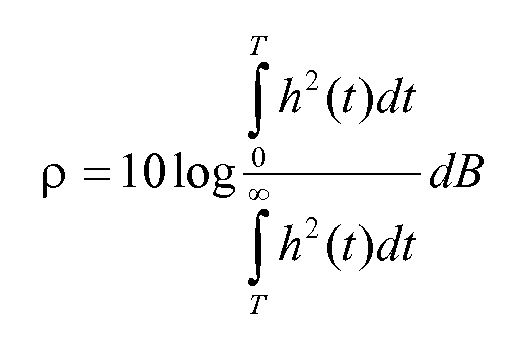
where h(t) is transfer function from the secondary microphone to the primary microphone, and T is designated boundary point on the time axis of h(t);
and then calculating regulatory factor β of the gain function according to the following formula:
where ρ 1 and ρ 2 are predetermined values. - The device of claim 7, characterized in that the gain function calculation unit is for calculating the gain function G(l,k) according to the following formula:

where l is frame number, k is frequency point number, β is regulatory factor of the gain function, R is late reverberation spectrum of the primary microphone input signal, and X 2 is frequency spectrum of the primary microphone input signal. - The device of claim 7, characterized in that the transfer function tail section calculation unit is specifically for taking a boundary point between early reverberation and late reverberation on the time axis of the transfer function h(t) and setting the values of the transfer function h(t) before the boundary point to be 0, thereby obtaining the tail section hr (t) of the transfer function h(t).
Applications Claiming Priority (2)
| Application Number | Priority Date | Filing Date | Title |
|---|---|---|---|
| CN201210536578.XA CN103067821B (en) | 2012-12-12 | 2012-12-12 | Method of and device for reducing voice reverberation based on double microphones |
| PCT/CN2013/001557 WO2014089914A1 (en) | 2012-12-12 | 2013-12-12 | Voice reverberation reduction method and device based on dual microphones |
Publications (3)
| Publication Number | Publication Date |
|---|---|
| EP2858379A1 true EP2858379A1 (en) | 2015-04-08 |
| EP2858379A4 EP2858379A4 (en) | 2015-11-11 |
| EP2858379B1 EP2858379B1 (en) | 2018-10-31 |
Family
ID=48110252
Family Applications (1)
| Application Number | Title | Priority Date | Filing Date |
|---|---|---|---|
| EP13863250.0A Active EP2858379B1 (en) | 2012-12-12 | 2013-12-12 | Voice reverberation reduction method and device based on dual microphones |
Country Status (7)
| Country | Link |
|---|---|
| US (1) | US9414157B2 (en) |
| EP (1) | EP2858379B1 (en) |
| JP (1) | JP5785674B2 (en) |
| KR (1) | KR101502297B1 (en) |
| CN (1) | CN103067821B (en) |
| DK (1) | DK2858379T3 (en) |
| WO (1) | WO2014089914A1 (en) |
Families Citing this family (11)
| Publication number | Priority date | Publication date | Assignee | Title |
|---|---|---|---|---|
| CN103067821B (en) * | 2012-12-12 | 2015-03-11 | 歌尔声学股份有限公司 | Method of and device for reducing voice reverberation based on double microphones |
| CN104156553B (en) * | 2014-05-09 | 2018-08-17 | 哈尔滨工业大学深圳研究生院 | Coherent signal Wave arrival direction estimating method and system without Sources number estimation |
| CN105848052B (en) * | 2015-01-16 | 2019-10-11 | 宇龙计算机通信科技(深圳)有限公司 | A microphone switching method and terminal |
| GB2549103B (en) * | 2016-04-04 | 2021-05-05 | Toshiba Res Europe Limited | A speech processing system and speech processing method |
| CN110660404B (en) * | 2019-09-19 | 2021-12-07 | 北京声加科技有限公司 | Voice communication and interactive application system and method based on null filtering preprocessing |
| EP3809726B1 (en) * | 2019-10-17 | 2025-12-31 | Bang & Olufsen A/S | ECHO-BASED SPACE ESTIMATION |
| CN111179958A (en) * | 2020-01-08 | 2020-05-19 | 厦门亿联网络技术股份有限公司 | Method and system for inhibiting late reverberation of voice |
| CN112053698A (en) * | 2020-07-31 | 2020-12-08 | 出门问问信息科技有限公司 | Voice conversion method and device |
| CN113542980B (en) * | 2021-07-21 | 2023-03-31 | 深圳市悦尔声学有限公司 | Method for inhibiting loudspeaker crosstalk |
| CN115019819B (en) * | 2022-05-30 | 2025-06-24 | 万兴科技(湖南)有限公司 | Audio processing method, device, equipment and medium based on gain compensation |
| CN115278455B (en) * | 2022-06-27 | 2025-06-17 | 深圳市奥维克通讯技术有限公司 | Audio processing method, device, conference microphone and computer-readable storage medium |
Family Cites Families (16)
| Publication number | Priority date | Publication date | Assignee | Title |
|---|---|---|---|---|
| JP3649847B2 (en) * | 1996-03-25 | 2005-05-18 | 日本電信電話株式会社 | Reverberation removal method and apparatus |
| BR9702254B1 (en) * | 1996-05-31 | 2009-12-01 | system for suppressing an interfering component in an input signal and speakerphone. | |
| US6549586B2 (en) * | 1999-04-12 | 2003-04-15 | Telefonaktiebolaget L M Ericsson | System and method for dual microphone signal noise reduction using spectral subtraction |
| EP1879181B1 (en) * | 2006-07-11 | 2014-05-21 | Nuance Communications, Inc. | Method for compensation audio signal components in a vehicle communication system and system therefor |
| JP5166117B2 (en) * | 2008-05-20 | 2013-03-21 | 株式会社船井電機新応用技術研究所 | Voice input device, manufacturing method thereof, and information processing system |
| EP2211564B1 (en) * | 2009-01-23 | 2014-09-10 | Harman Becker Automotive Systems GmbH | Passenger compartment communication system |
| US8233352B2 (en) * | 2009-08-17 | 2012-07-31 | Broadcom Corporation | Audio source localization system and method |
| US8897455B2 (en) * | 2010-02-18 | 2014-11-25 | Qualcomm Incorporated | Microphone array subset selection for robust noise reduction |
| CN101976565A (en) | 2010-07-09 | 2011-02-16 | 瑞声声学科技(深圳)有限公司 | Dual-microphone-based speech enhancement device and method |
| JP2012048133A (en) | 2010-08-30 | 2012-03-08 | Nippon Telegr & Teleph Corp <Ntt> | Reverberation removal method, reverberation removal device and program |
| JP5594133B2 (en) * | 2010-12-28 | 2014-09-24 | ソニー株式会社 | Audio signal processing apparatus, audio signal processing method, and program |
| CN102347028A (en) * | 2011-07-14 | 2012-02-08 | 瑞声声学科技(深圳)有限公司 | Double-microphone speech enhancer and speech enhancement method thereof |
| CN203243506U (en) * | 2012-12-12 | 2013-10-16 | 歌尔声学股份有限公司 | Voice reverberation reducing device based on two microphones |
| CN103067821B (en) * | 2012-12-12 | 2015-03-11 | 歌尔声学股份有限公司 | Method of and device for reducing voice reverberation based on double microphones |
| CN103087821B (en) | 2013-01-15 | 2016-09-07 | 武汉工业学院 | A kind of rice bran oil refining method retaining oryzanol |
| US9100762B2 (en) * | 2013-05-22 | 2015-08-04 | Gn Resound A/S | Hearing aid with improved localization |
-
2012
- 2012-12-12 CN CN201210536578.XA patent/CN103067821B/en active Active
-
2013
- 2013-12-12 WO PCT/CN2013/001557 patent/WO2014089914A1/en not_active Ceased
- 2013-12-12 EP EP13863250.0A patent/EP2858379B1/en active Active
- 2013-12-12 DK DK13863250.0T patent/DK2858379T3/en active
- 2013-12-12 KR KR1020147036443A patent/KR101502297B1/en active Active
- 2013-12-12 US US14/411,651 patent/US9414157B2/en active Active
- 2013-12-12 JP JP2015524601A patent/JP5785674B2/en active Active
Non-Patent Citations (6)
| Title |
|---|
| KNAPP C H ET AL: "The generalized correlation method for estimation of time delay", IEEE TRANSACTIONS ON ACOUSTICS, SPEECH AND SIGNAL PROCESSING, IEEE INC. NEW YORK, USA, vol. ASSP-24, no. 4, 1 August 1976 (1976-08-01), pages 320 - 327, XP002281206, ISSN: 0096-3518, DOI: 10.1109/TASSP.1976.1162830 * |
| LEBART K ET AL: "A NEW METHOD BASED ON SPECTRAL SUBTRACTION FOR SPEECH DEREVERBERATION", ACUSTICA, S. HIRZEL VERLAG, STUTTGART, DE, vol. 87, no. 3, 1 May 2001 (2001-05-01), pages 359 - 366, XP009053193, ISSN: 0001-7884 * |
| LIM J S ET AL: "ENHANCEMENT AND BANDWIDTH COMPRESSION OF NOISY SPEECH", PROCEEDINGS OF THE IEEE, IEEE. NEW YORK, US, vol. 67, no. 12, 1 December 1979 (1979-12-01), pages 1586 - 1604, XP000891496, ISSN: 0018-9219 * |
| MIYOSHI M ET AL: "INVERSE FILTERING OF ROOM ACOUSTICS", IEEE TRANSACTIONS ON ACOUSTICS, SPEECH AND SIGNAL PROCESSING, IEEE INC. NEW YORK, USA, vol. 36, no. 2, 1 February 1988 (1988-02-01), pages 145 - 152, XP000005739, ISSN: 0096-3518, DOI: 10.1109/29.1509 * |
| NATHALIE VIRAG: "Single Channel Speech Enhancement Based on Masking Properties of the Human Auditory System", IEEE TRANSACTIONS ON SPEECH AND AUDIO PROCESSING, IEEE SERVICE CENTER, NEW YORK, NY, US, vol. 7, no. 2, 1 March 1999 (1999-03-01), XP011054357, ISSN: 1063-6676 * |
| See also references of WO2014089914A1 * |
Also Published As
| Publication number | Publication date |
|---|---|
| US20150189431A1 (en) | 2015-07-02 |
| JP2015523609A (en) | 2015-08-13 |
| US9414157B2 (en) | 2016-08-09 |
| WO2014089914A1 (en) | 2014-06-19 |
| CN103067821A (en) | 2013-04-24 |
| EP2858379A4 (en) | 2015-11-11 |
| KR20150008925A (en) | 2015-01-23 |
| DK2858379T3 (en) | 2019-01-21 |
| EP2858379B1 (en) | 2018-10-31 |
| JP5785674B2 (en) | 2015-09-30 |
| CN103067821B (en) | 2015-03-11 |
| KR101502297B1 (en) | 2015-03-12 |
Similar Documents
| Publication | Publication Date | Title |
|---|---|---|
| EP2858379B1 (en) | Voice reverberation reduction method and device based on dual microphones | |
| EP2701145B1 (en) | Noise estimation for use with noise reduction and echo cancellation in personal communication | |
| US9768829B2 (en) | Methods for processing audio signals and circuit arrangements therefor | |
| US9685172B2 (en) | Method and device for suppressing residual echoes based on inverse transmitter receiver distance and delay for speech signals directly incident on a transmitter array | |
| EP2393463B1 (en) | Multiple microphone based directional sound filter | |
| EP3833041A1 (en) | Earphone signal processing method and system, and earphone | |
| US8867759B2 (en) | System and method for utilizing inter-microphone level differences for speech enhancement | |
| EP2237271B1 (en) | Method for determining a signal component for reducing noise in an input signal | |
| EP3120355B1 (en) | Noise suppression | |
| EP2141695B1 (en) | Speech sound enhancement device | |
| US8712075B2 (en) | Spatially pre-processed target-to-jammer ratio weighted filter and method thereof | |
| US8218780B2 (en) | Methods and systems for blind dereverberation | |
| EP2905778A1 (en) | Echo cancellation method and device | |
| US7555075B2 (en) | Adjustable noise suppression system | |
| CN103874002A (en) | Audio processing device comprising reduced artifacts | |
| CN104157295A (en) | Method used for detecting and suppressing transient noise | |
| CN103295582B (en) | Noise suppressing method and system thereof | |
| CN203243506U (en) | Voice reverberation reducing device based on two microphones | |
| Yu et al. | Speech enhancement based on the generalized sidelobe cancellation and spectral subtraction for a microphone array | |
| EP2816817B1 (en) | Sound field spatial stabilizer with spectral coherence compensation | |
| EP2816818B1 (en) | Sound field spatial stabilizer with echo spectral coherence compensation | |
| Ngo et al. | Variable speech distortion weighted multichannel wiener filter based on soft output voice activity detection for noise reduction in hearing aids | |
| EP2816816B1 (en) | Sound field spatial stabilizer with structured noise compensation | |
| JP4209348B2 (en) | Echo suppression method, apparatus for implementing this method, program, and recording medium |
Legal Events
| Date | Code | Title | Description |
|---|---|---|---|
| PUAI | Public reference made under article 153(3) epc to a published international application that has entered the european phase |
Free format text: ORIGINAL CODE: 0009012 |
|
| 17P | Request for examination filed |
Effective date: 20141231 |
|
| AK | Designated contracting states |
Kind code of ref document: A1 Designated state(s): AL AT BE BG CH CY CZ DE DK EE ES FI FR GB GR HR HU IE IS IT LI LT LU LV MC MK MT NL NO PL PT RO RS SE SI SK SM TR |
|
| AX | Request for extension of the european patent |
Extension state: BA ME |
|
| RA4 | Supplementary search report drawn up and despatched (corrected) |
Effective date: 20151012 |
|
| RIC1 | Information provided on ipc code assigned before grant |
Ipc: H04R 3/00 20060101AFI20151006BHEP Ipc: G10L 21/02 20130101ALI20151006BHEP |
|
| 17Q | First examination report despatched |
Effective date: 20151214 |
|
| DAX | Request for extension of the european patent (deleted) | ||
| STAA | Information on the status of an ep patent application or granted ep patent |
Free format text: STATUS: EXAMINATION IS IN PROGRESS |
|
| GRAP | Despatch of communication of intention to grant a patent |
Free format text: ORIGINAL CODE: EPIDOSNIGR1 |
|
| STAA | Information on the status of an ep patent application or granted ep patent |
Free format text: STATUS: GRANT OF PATENT IS INTENDED |
|
| INTG | Intention to grant announced |
Effective date: 20180704 |
|
| GRAS | Grant fee paid |
Free format text: ORIGINAL CODE: EPIDOSNIGR3 |
|
| GRAJ | Information related to disapproval of communication of intention to grant by the applicant or resumption of examination proceedings by the epo deleted |
Free format text: ORIGINAL CODE: EPIDOSDIGR1 |
|
| GRAL | Information related to payment of fee for publishing/printing deleted |
Free format text: ORIGINAL CODE: EPIDOSDIGR3 |
|
| STAA | Information on the status of an ep patent application or granted ep patent |
Free format text: STATUS: EXAMINATION IS IN PROGRESS |
|
| INTC | Intention to grant announced (deleted) | ||
| GRAR | Information related to intention to grant a patent recorded |
Free format text: ORIGINAL CODE: EPIDOSNIGR71 |
|
| STAA | Information on the status of an ep patent application or granted ep patent |
Free format text: STATUS: GRANT OF PATENT IS INTENDED |
|
| GRAA | (expected) grant |
Free format text: ORIGINAL CODE: 0009210 |
|
| STAA | Information on the status of an ep patent application or granted ep patent |
Free format text: STATUS: THE PATENT HAS BEEN GRANTED |
|
| AK | Designated contracting states |
Kind code of ref document: B1 Designated state(s): AL AT BE BG CH CY CZ DE DK EE ES FI FR GB GR HR HU IE IS IT LI LT LU LV MC MK MT NL NO PL PT RO RS SE SI SK SM TR |
|
| INTG | Intention to grant announced |
Effective date: 20180921 |
|
| REG | Reference to a national code |
Ref country code: CH Ref legal event code: EP Ref country code: GB Ref legal event code: FG4D |
|
| REG | Reference to a national code |
Ref country code: AT Ref legal event code: REF Ref document number: 1060837 Country of ref document: AT Kind code of ref document: T Effective date: 20181115 |
|
| REG | Reference to a national code |
Ref country code: DE Ref legal event code: R096 Ref document number: 602013046126 Country of ref document: DE |
|
| REG | Reference to a national code |
Ref country code: IE Ref legal event code: FG4D |
|
| REG | Reference to a national code |
Ref country code: DK Ref legal event code: T3 Effective date: 20190107 |
|
| REG | Reference to a national code |
Ref country code: NL Ref legal event code: MP Effective date: 20181031 |
|
| REG | Reference to a national code |
Ref country code: LT Ref legal event code: MG4D |
|
| REG | Reference to a national code |
Ref country code: AT Ref legal event code: MK05 Ref document number: 1060837 Country of ref document: AT Kind code of ref document: T Effective date: 20181031 |
|
| PG25 | Lapsed in a contracting state [announced via postgrant information from national office to epo] |
Ref country code: FI Free format text: LAPSE BECAUSE OF FAILURE TO SUBMIT A TRANSLATION OF THE DESCRIPTION OR TO PAY THE FEE WITHIN THE PRESCRIBED TIME-LIMIT Effective date: 20181031 Ref country code: IS Free format text: LAPSE BECAUSE OF FAILURE TO SUBMIT A TRANSLATION OF THE DESCRIPTION OR TO PAY THE FEE WITHIN THE PRESCRIBED TIME-LIMIT Effective date: 20190228 Ref country code: AT Free format text: LAPSE BECAUSE OF FAILURE TO SUBMIT A TRANSLATION OF THE DESCRIPTION OR TO PAY THE FEE WITHIN THE PRESCRIBED TIME-LIMIT Effective date: 20181031 Ref country code: NO Free format text: LAPSE BECAUSE OF FAILURE TO SUBMIT A TRANSLATION OF THE DESCRIPTION OR TO PAY THE FEE WITHIN THE PRESCRIBED TIME-LIMIT Effective date: 20190131 Ref country code: LV Free format text: LAPSE BECAUSE OF FAILURE TO SUBMIT A TRANSLATION OF THE DESCRIPTION OR TO PAY THE FEE WITHIN THE PRESCRIBED TIME-LIMIT Effective date: 20181031 Ref country code: PL Free format text: LAPSE BECAUSE OF FAILURE TO SUBMIT A TRANSLATION OF THE DESCRIPTION OR TO PAY THE FEE WITHIN THE PRESCRIBED TIME-LIMIT Effective date: 20181031 Ref country code: LT Free format text: LAPSE BECAUSE OF FAILURE TO SUBMIT A TRANSLATION OF THE DESCRIPTION OR TO PAY THE FEE WITHIN THE PRESCRIBED TIME-LIMIT Effective date: 20181031 Ref country code: HR Free format text: LAPSE BECAUSE OF FAILURE TO SUBMIT A TRANSLATION OF THE DESCRIPTION OR TO PAY THE FEE WITHIN THE PRESCRIBED TIME-LIMIT Effective date: 20181031 Ref country code: ES Free format text: LAPSE BECAUSE OF FAILURE TO SUBMIT A TRANSLATION OF THE DESCRIPTION OR TO PAY THE FEE WITHIN THE PRESCRIBED TIME-LIMIT Effective date: 20181031 Ref country code: BG Free format text: LAPSE BECAUSE OF FAILURE TO SUBMIT A TRANSLATION OF THE DESCRIPTION OR TO PAY THE FEE WITHIN THE PRESCRIBED TIME-LIMIT Effective date: 20190131 |
|
| PG25 | Lapsed in a contracting state [announced via postgrant information from national office to epo] |
Ref country code: AL Free format text: LAPSE BECAUSE OF FAILURE TO SUBMIT A TRANSLATION OF THE DESCRIPTION OR TO PAY THE FEE WITHIN THE PRESCRIBED TIME-LIMIT Effective date: 20181031 Ref country code: NL Free format text: LAPSE BECAUSE OF FAILURE TO SUBMIT A TRANSLATION OF THE DESCRIPTION OR TO PAY THE FEE WITHIN THE PRESCRIBED TIME-LIMIT Effective date: 20181031 Ref country code: PT Free format text: LAPSE BECAUSE OF FAILURE TO SUBMIT A TRANSLATION OF THE DESCRIPTION OR TO PAY THE FEE WITHIN THE PRESCRIBED TIME-LIMIT Effective date: 20190301 Ref country code: GR Free format text: LAPSE BECAUSE OF FAILURE TO SUBMIT A TRANSLATION OF THE DESCRIPTION OR TO PAY THE FEE WITHIN THE PRESCRIBED TIME-LIMIT Effective date: 20190201 Ref country code: SE Free format text: LAPSE BECAUSE OF FAILURE TO SUBMIT A TRANSLATION OF THE DESCRIPTION OR TO PAY THE FEE WITHIN THE PRESCRIBED TIME-LIMIT Effective date: 20181031 Ref country code: RS Free format text: LAPSE BECAUSE OF FAILURE TO SUBMIT A TRANSLATION OF THE DESCRIPTION OR TO PAY THE FEE WITHIN THE PRESCRIBED TIME-LIMIT Effective date: 20181031 |
|
| PG25 | Lapsed in a contracting state [announced via postgrant information from national office to epo] |
Ref country code: IT Free format text: LAPSE BECAUSE OF FAILURE TO SUBMIT A TRANSLATION OF THE DESCRIPTION OR TO PAY THE FEE WITHIN THE PRESCRIBED TIME-LIMIT Effective date: 20181031 Ref country code: CZ Free format text: LAPSE BECAUSE OF FAILURE TO SUBMIT A TRANSLATION OF THE DESCRIPTION OR TO PAY THE FEE WITHIN THE PRESCRIBED TIME-LIMIT Effective date: 20181031 |
|
| REG | Reference to a national code |
Ref country code: CH Ref legal event code: PL |
|
| REG | Reference to a national code |
Ref country code: DE Ref legal event code: R097 Ref document number: 602013046126 Country of ref document: DE |
|
| PG25 | Lapsed in a contracting state [announced via postgrant information from national office to epo] |
Ref country code: SM Free format text: LAPSE BECAUSE OF FAILURE TO SUBMIT A TRANSLATION OF THE DESCRIPTION OR TO PAY THE FEE WITHIN THE PRESCRIBED TIME-LIMIT Effective date: 20181031 Ref country code: EE Free format text: LAPSE BECAUSE OF FAILURE TO SUBMIT A TRANSLATION OF THE DESCRIPTION OR TO PAY THE FEE WITHIN THE PRESCRIBED TIME-LIMIT Effective date: 20181031 Ref country code: SK Free format text: LAPSE BECAUSE OF FAILURE TO SUBMIT A TRANSLATION OF THE DESCRIPTION OR TO PAY THE FEE WITHIN THE PRESCRIBED TIME-LIMIT Effective date: 20181031 Ref country code: RO Free format text: LAPSE BECAUSE OF FAILURE TO SUBMIT A TRANSLATION OF THE DESCRIPTION OR TO PAY THE FEE WITHIN THE PRESCRIBED TIME-LIMIT Effective date: 20181031 Ref country code: LU Free format text: LAPSE BECAUSE OF NON-PAYMENT OF DUE FEES Effective date: 20181212 Ref country code: MC Free format text: LAPSE BECAUSE OF FAILURE TO SUBMIT A TRANSLATION OF THE DESCRIPTION OR TO PAY THE FEE WITHIN THE PRESCRIBED TIME-LIMIT Effective date: 20181031 |
|
| PLBE | No opposition filed within time limit |
Free format text: ORIGINAL CODE: 0009261 |
|
| STAA | Information on the status of an ep patent application or granted ep patent |
Free format text: STATUS: NO OPPOSITION FILED WITHIN TIME LIMIT |
|
| REG | Reference to a national code |
Ref country code: IE Ref legal event code: MM4A |
|
| REG | Reference to a national code |
Ref country code: BE Ref legal event code: MM Effective date: 20181231 |
|
| 26N | No opposition filed |
Effective date: 20190801 |
|
| PG25 | Lapsed in a contracting state [announced via postgrant information from national office to epo] |
Ref country code: IE Free format text: LAPSE BECAUSE OF NON-PAYMENT OF DUE FEES Effective date: 20181212 Ref country code: SI Free format text: LAPSE BECAUSE OF FAILURE TO SUBMIT A TRANSLATION OF THE DESCRIPTION OR TO PAY THE FEE WITHIN THE PRESCRIBED TIME-LIMIT Effective date: 20181031 |
|
| PG25 | Lapsed in a contracting state [announced via postgrant information from national office to epo] |
Ref country code: BE Free format text: LAPSE BECAUSE OF NON-PAYMENT OF DUE FEES Effective date: 20181231 |
|
| PG25 | Lapsed in a contracting state [announced via postgrant information from national office to epo] |
Ref country code: CH Free format text: LAPSE BECAUSE OF NON-PAYMENT OF DUE FEES Effective date: 20181231 Ref country code: LI Free format text: LAPSE BECAUSE OF NON-PAYMENT OF DUE FEES Effective date: 20181231 |
|
| PG25 | Lapsed in a contracting state [announced via postgrant information from national office to epo] |
Ref country code: MT Free format text: LAPSE BECAUSE OF NON-PAYMENT OF DUE FEES Effective date: 20181212 |
|
| PG25 | Lapsed in a contracting state [announced via postgrant information from national office to epo] |
Ref country code: TR Free format text: LAPSE BECAUSE OF FAILURE TO SUBMIT A TRANSLATION OF THE DESCRIPTION OR TO PAY THE FEE WITHIN THE PRESCRIBED TIME-LIMIT Effective date: 20181031 |
|
| PG25 | Lapsed in a contracting state [announced via postgrant information from national office to epo] |
Ref country code: HU Free format text: LAPSE BECAUSE OF FAILURE TO SUBMIT A TRANSLATION OF THE DESCRIPTION OR TO PAY THE FEE WITHIN THE PRESCRIBED TIME-LIMIT; INVALID AB INITIO Effective date: 20131212 |
|
| PG25 | Lapsed in a contracting state [announced via postgrant information from national office to epo] |
Ref country code: MK Free format text: LAPSE BECAUSE OF NON-PAYMENT OF DUE FEES Effective date: 20181031 Ref country code: CY Free format text: LAPSE BECAUSE OF FAILURE TO SUBMIT A TRANSLATION OF THE DESCRIPTION OR TO PAY THE FEE WITHIN THE PRESCRIBED TIME-LIMIT Effective date: 20181031 |
|
| REG | Reference to a national code |
Ref country code: DE Ref legal event code: R082 Ref document number: 602013046126 Country of ref document: DE Representative=s name: LKGLOBAL | LORENZ & KOPF PARTG MBB PATENTANWAE, DE Ref country code: DE Ref legal event code: R081 Ref document number: 602013046126 Country of ref document: DE Owner name: WEIFANG GOERTEK MICROELECTRONICS CO., LTD., WE, CN Free format text: FORMER OWNER: GOERTEK INC., WEIFANG, SHANDONG, CN |
|
| REG | Reference to a national code |
Ref country code: GB Ref legal event code: 732E Free format text: REGISTERED BETWEEN 20201015 AND 20201021 |
|
| PGFP | Annual fee paid to national office [announced via postgrant information from national office to epo] |
Ref country code: GB Payment date: 20251229 Year of fee payment: 13 |
|
| PGFP | Annual fee paid to national office [announced via postgrant information from national office to epo] |
Ref country code: DK Payment date: 20251127 Year of fee payment: 13 |
|
| PGFP | Annual fee paid to national office [announced via postgrant information from national office to epo] |
Ref country code: FR Payment date: 20251230 Year of fee payment: 13 |
|
| PGFP | Annual fee paid to national office [announced via postgrant information from national office to epo] |
Ref country code: DE Payment date: 20251231 Year of fee payment: 13 |