EP2858124A1 - Bridged solar cell and solar power generation system - Google Patents
Bridged solar cell and solar power generation system Download PDFInfo
- Publication number
- EP2858124A1 EP2858124A1 EP12877403.1A EP12877403A EP2858124A1 EP 2858124 A1 EP2858124 A1 EP 2858124A1 EP 12877403 A EP12877403 A EP 12877403A EP 2858124 A1 EP2858124 A1 EP 2858124A1
- Authority
- EP
- European Patent Office
- Prior art keywords
- solar cell
- bus bar
- insulation film
- bar electrodes
- bridged
- Prior art date
- Legal status (The legal status is an assumption and is not a legal conclusion. Google has not performed a legal analysis and makes no representation as to the accuracy of the status listed.)
- Granted
Links
Images


Classifications
-
- H—ELECTRICITY
- H10—SEMICONDUCTOR DEVICES; ELECTRIC SOLID-STATE DEVICES NOT OTHERWISE PROVIDED FOR
- H10F—INORGANIC SEMICONDUCTOR DEVICES SENSITIVE TO INFRARED RADIATION, LIGHT, ELECTROMAGNETIC RADIATION OF SHORTER WAVELENGTH OR CORPUSCULAR RADIATION
- H10F77/00—Constructional details of devices covered by this subclass
- H10F77/20—Electrodes
- H10F77/206—Electrodes for devices having potential barriers
- H10F77/211—Electrodes for devices having potential barriers for photovoltaic cells
- H10F77/215—Geometries of grid contacts
-
- H—ELECTRICITY
- H02—GENERATION; CONVERSION OR DISTRIBUTION OF ELECTRIC POWER
- H02S—GENERATION OF ELECTRIC POWER BY CONVERSION OF INFRARED RADIATION, VISIBLE LIGHT OR ULTRAVIOLET LIGHT, e.g. USING PHOTOVOLTAIC [PV] MODULES
- H02S40/00—Components or accessories in combination with PV modules, not provided for in groups H02S10/00 - H02S30/00
- H02S40/30—Electrical components
- H02S40/36—Electrical components characterised by special electrical interconnection means between two or more PV modules, e.g. electrical module-to-module connection
-
- H—ELECTRICITY
- H10—SEMICONDUCTOR DEVICES; ELECTRIC SOLID-STATE DEVICES NOT OTHERWISE PROVIDED FOR
- H10F—INORGANIC SEMICONDUCTOR DEVICES SENSITIVE TO INFRARED RADIATION, LIGHT, ELECTROMAGNETIC RADIATION OF SHORTER WAVELENGTH OR CORPUSCULAR RADIATION
- H10F19/00—Integrated devices, or assemblies of multiple devices, comprising at least one photovoltaic cell covered by group H10F10/00, e.g. photovoltaic modules
- H10F19/90—Structures for connecting between photovoltaic cells, e.g. interconnections or insulating spacers
- H10F19/902—Structures for connecting between photovoltaic cells, e.g. interconnections or insulating spacers for series or parallel connection of photovoltaic cells
-
- H—ELECTRICITY
- H10—SEMICONDUCTOR DEVICES; ELECTRIC SOLID-STATE DEVICES NOT OTHERWISE PROVIDED FOR
- H10F—INORGANIC SEMICONDUCTOR DEVICES SENSITIVE TO INFRARED RADIATION, LIGHT, ELECTROMAGNETIC RADIATION OF SHORTER WAVELENGTH OR CORPUSCULAR RADIATION
- H10F19/00—Integrated devices, or assemblies of multiple devices, comprising at least one photovoltaic cell covered by group H10F10/00, e.g. photovoltaic modules
- H10F19/90—Structures for connecting between photovoltaic cells, e.g. interconnections or insulating spacers
- H10F19/902—Structures for connecting between photovoltaic cells, e.g. interconnections or insulating spacers for series or parallel connection of photovoltaic cells
- H10F19/904—Structures for connecting between photovoltaic cells, e.g. interconnections or insulating spacers for series or parallel connection of photovoltaic cells characterised by the shapes of the structures
-
- H—ELECTRICITY
- H10—SEMICONDUCTOR DEVICES; ELECTRIC SOLID-STATE DEVICES NOT OTHERWISE PROVIDED FOR
- H10F—INORGANIC SEMICONDUCTOR DEVICES SENSITIVE TO INFRARED RADIATION, LIGHT, ELECTROMAGNETIC RADIATION OF SHORTER WAVELENGTH OR CORPUSCULAR RADIATION
- H10F77/00—Constructional details of devices covered by this subclass
- H10F77/93—Interconnections
- H10F77/933—Interconnections for devices having potential barriers
- H10F77/935—Interconnections for devices having potential barriers for photovoltaic devices or modules
- H10F77/937—Busbar structures for modules
-
- Y—GENERAL TAGGING OF NEW TECHNOLOGICAL DEVELOPMENTS; GENERAL TAGGING OF CROSS-SECTIONAL TECHNOLOGIES SPANNING OVER SEVERAL SECTIONS OF THE IPC; TECHNICAL SUBJECTS COVERED BY FORMER USPC CROSS-REFERENCE ART COLLECTIONS [XRACs] AND DIGESTS
- Y02—TECHNOLOGIES OR APPLICATIONS FOR MITIGATION OR ADAPTATION AGAINST CLIMATE CHANGE
- Y02E—REDUCTION OF GREENHOUSE GAS [GHG] EMISSIONS, RELATED TO ENERGY GENERATION, TRANSMISSION OR DISTRIBUTION
- Y02E10/00—Energy generation through renewable energy sources
- Y02E10/50—Photovoltaic [PV] energy
-
- Y—GENERAL TAGGING OF NEW TECHNOLOGICAL DEVELOPMENTS; GENERAL TAGGING OF CROSS-SECTIONAL TECHNOLOGIES SPANNING OVER SEVERAL SECTIONS OF THE IPC; TECHNICAL SUBJECTS COVERED BY FORMER USPC CROSS-REFERENCE ART COLLECTIONS [XRACs] AND DIGESTS
- Y02—TECHNOLOGIES OR APPLICATIONS FOR MITIGATION OR ADAPTATION AGAINST CLIMATE CHANGE
- Y02E—REDUCTION OF GREENHOUSE GAS [GHG] EMISSIONS, RELATED TO ENERGY GENERATION, TRANSMISSION OR DISTRIBUTION
- Y02E10/00—Energy generation through renewable energy sources
- Y02E10/50—Photovoltaic [PV] energy
- Y02E10/547—Monocrystalline silicon PV cells
Definitions
- the present disclosure relates to a bridged solar cell and a solar power generation system.
- a bridged solar cell includes a substrate, a first set of bus bar electrodes, a second set of bus bar electrodes, a first welding member, a first insulation film, a third set of bus bar electrodes, and a second welding member.
- the substrate has a front surface and a back surface.
- the first set of bus bar electrodes is disposed on the front surface along a first direction.
- the second set of bus bar electrodes is disposed on the back surface along a second direction different from the first direction and electrically connected to the first set of bus bar electrodes via the substrate.
- the first welding member is electrically connected to the second set of bus bar electrodes.
- the first insulation film is disposed on the back surface.
- the third set of bus bar electrodes is disposed on the first insulation film along the second direction so as to be insulated from the substrate.
- the second welding member is disposed on the first insulation film and electrically connected to the third set of bus bar electrodes.
- the portion of the first welding member extended onto the second insulation film and the portion of the second welding member covered by the second insulation film are respectively located at two opposite surfaces of the second insulation film.
- the second welding member includes a coupling portion and a terminal portion.
- the coupling portion is coupled to the third set of bus bar electrodes.
- the terminal portion is connected to the coupling portion.
- the coupling portion and the terminal portion form an L-shaped structure or a T-shaped structure.
- a solar power generation system includes a plurality of solar cell modules.
- Each of the solar cell modules includes a first solar cell string and a junction box.
- the first solar cell string includes a plurality of first solar cells and a first bridged solar cell.
- the first solar cells and the first bridged solar cell are connected in series along a first direction.
- the first bridged solar cell includes a substrate, a first set of bus bar electrodes, a second set of bus bar electrodes, a first welding member, a first insulation film, a third set of bus bar electrodes, and a second welding member.
- the substrate has a front surface and a back surface.
- the first set of bus bar electrodes is disposed on the front surface along the first direction.
- the junction box is disposed on the back surface.
- An improved solar power generation system is provided. Particularly, the direction along which two sets of bus bar electrodes are disposed on a back surface of a bridged solar cell is different from the direction along which bus bar electrodes are disposed on a front surface of the bridged solar cell (e.g., the direction along which the sets of bus bar electrodes are disposed on the back surface of a bridged solar cell is perpendicular to the direction along which the bus bar electrodes are disposed on the front surface of the bridged solar cell).
- Fig. 1 is a schematic diagram of a solar power generation system 1 according to an embodiment of the disclosure.
- the solar power generation system 1 includes a plurality of solar cell modules 10 and an inverter 12.
- the solar cell modules 10 of the solar power generation system 1 are arranged in two rows from the inverter 12 substantially along a direction.
- the positive and negative terminals of the inverter 12 of the solar power generation system 1 are respectively connected to the two rows of the solar cell modules 10, and the two solar cell modules 10 farthest from the inverter 12 respectively in the two rows of the solar cell modules 10 are coupled to each other so as to form a complete loop.
- each of the solar cell modules 10 of the solar power generation system 1 includes junction boxes 108.
- Fig. 2 is a schematic diagram of a solar cell module 10 in Fig. 1 .
- Fig. 3 is a partial schematic diagram of an embodiment of a first bridged solar cell 100 and a second bridged solar cell 104 in Fig. 2 .
- Fig. 4 is a partial sectional view of the first bridged solar cell 100 and the second bridged solar cell 104 along line 4-4' in Fig. 3 .
- each of the solar cell modules 10 includes a first solar cell string 10a.
- the first solar cell string 10a of the solar cell module 10 includes a plurality of first solar cells 102 and at least one first bridged solar cell 100 (the first solar cell string 10a includes only one first bridged solar cell 100 in this embodiment).
- the first solar cells 102 of the first solar cell string 10a are electrically connected in series along a first direction D1, and the first bridged solar cell 100 is electrically connected to an end of the first solar cells 102 (i.e., the upper end of the first solar cells 102 shown in Fig. 2 ).
- the first bridged solar cell 100 of the solar cell module 10 includes a substrate 100a, a first set of bus bar electrodes 100b, a second set of bus bar electrodes 100c, a first welding member 100d, a first insulation film 100e, a third set of bus bar electrodes 100g, and a second welding member 100f.
- the substrate 100a of the first bridged solar cell 100 has a front surface 100a1 and a back surface 100a2.
- the first set of bus bar electrodes 100b of the first bridged solar cell 100 is disposed on the front surface 100a1 of the substrate 100a along the first direction D1.
- the substrate 100 of the first bridged solar cell 100 can electrically interconnect the first set of bus bar electrodes 100b and the second set of bus bar electrodes 100c.
- the substrate 100 includes an N-type semiconductor layer and a P-type semiconductor layer (not shown).
- the N-type semiconductor layer of the substrate 100 is electrically connected to the first set of bus bar electrodes 100b
- the P-type semiconductor layer of the substrate 100 is electrically connected to the second set of bus bar electrodes 100c.
- the N-type semiconductor layer of the substrate 100 can be stimulated to emit free electrons after receiving light. Due to the potential difference, the free electrons flow to holes in the P-type semiconductor layer, thereby generating a current and thus electrically interconnecting the first set of bus bar electrodes 100b and the second set of bus bar electrodes 100c.
- the first welding member 100d of the first bridged solar cell 100 is electrically connected to the second set of bus bar electrodes 100c.
- the first insulation film 100e of the first bridged solar cell 100 is disposed on the back surface 100a2 of the substrate 100a.
- the third set of bus bar electrodes 100g of the first bridged solar cell 100 is disposed on the first insulation film 100e along the second direction D2 so as to be insulated from the substrate 100a.
- the second welding member 100f of the first bridged solar cell 100 is disposed on the first insulation film 100e and electrically connected to the third set of bus bar electrodes 100g.
- the first welding member 100d of the first bridged solar cell 100 includes a coupling portion 100d1 and a terminal portion 100d2.
- the coupling portion 100d1 of the first welding member 100d is coupled to the second set of bus bar electrodes 100c.
- the terminal portion 100d2 of the first welding member 100d is connected to the coupling portion 100d1.
- the coupling portion 100d1 and the terminal portion 100d2 of the first welding member 100d form an L-shaped structure, but the invention is not limited in this regard.
- the second welding member 100f of the first bridged solar cell 100 includes a coupling portion 100f1 and a terminal portion 100f2.
- the coupling portion 100f1 of the second welding member 100f is coupled to the third set of bus bar electrodes 100g.
- the terminal portion 100f2 of the second welding member 100f is connected to the coupling portion 100f1.
- the coupling portion 100f1 and the terminal portion 100f2 of the second welding member 100f form an L-shaped structure.
- the junction box 108 of the solar cell module 10 can be electrically connected to the terminal portion 100d2 of the first welding member 100d and the terminal portion 100f2 of the second welding member 100f, thereby electrically connecting to another junction box 108 of another adjacent solar cell module 10.
- each of the solar cell modules 10 further includes a second solar cell string 10b.
- the second solar cell string 10b of the solar cell module 10 includes a plurality of second solar cells 106 and at least one second bridged solar cell 104 (the second solar cell string 10b includes only one second bridged solar cell 104 in this embodiment).
- the second solar cells 106 of the second solar cell string 10b are electrically connected in series along the first direction D1, and the second bridged solar cell 104 is electrically connected to an end of the second solar cells 106 (i.e., the upper end of the second solar cells 106 shown in Fig. 2 ).
- the second bridged solar cell 104 of the second solar cell string 10b includes another substrate 104a.
- the substrate 104a of the second bridged solar cell 104 has another front surface 104a1.
- the third set of bus bar electrodes 100g of the first bridged solar cell 100 is extended onto the front surface 104a1 of the substrate 104a of the second bridged solar cell 104 from the back surface 100a2 of the substrate 100a.
- the third set of bus bar electrodes 100g of the first bridged solar cell 100 that is located on the back surface 100a2 of the substrate 100a are directly extended onto the another front surface 104a1 of the second bridged solar cell 104 of the second solar cell string 10b and act as the bus bar electrodes on the front surface 100a1 of the second bridged solar cell 104.
- the third set of bus bar electrodes 100g is shared by the first bridged solar cell 100 and the second bridged solar cell 104, and is electrically connected to the back surface 100a2 of the substrate 100a of the first bridged solar cell 100 and the front surface 104a1 of the substrate 104a of the second bridged solar cell 104.
- the third set of bus bar electrodes 100g is described as a component included in the first bridged solar cell 100 above, the third set of bus bar electrodes 100g can also be regarded as a component included in the second bridged solar cell 104.
- the solar power generation system 1 of the disclosure does not need to utilize a region adjacent to an upper edge and a region adjacent to a lower edge of a glass substrate (not shown) of each of the solar cell modules 10 for electrical connection by using bussing ribbons. Accordingly, not only can the total area of the glass substrates of the solar cell modules 10 be reduced, but the total length of the bussing ribbons used in the solar cell modules 10 can also be reduced, so as to achieve the advantages of saving costs of related materials and reducing energy loss. For example, because bussing ribbons need to be installed in the regions respectively adjacent to the upper and lower edges of a glass substrate of a conventional solar cell module, the length and width of the glass substrate of the conventional solar cell module are respectively 1668 mm and 1000 mm. In contrast, bussing ribbons for electrical connection are unnecessary in the solar cell module 10 of the disclosure, and so the length and width of the glass substrate used in the solar cell module 10 can be reduced to 1611 mm and 983 mm respectively.
- the first bridged solar cell 100 of the first solar cell string 10a further includes a packaging member 100h adhered under the first insulation film 100e and located between the first insulation film 100e and the back surface 100a2 of the substrate 100a.
- the first insulation film 100e of the first bridged solar cell 100 has a protruding portion 100e1.
- the protruding portion 100e1 of the first insulation film 100e protrudes outwardly from an edge of the back surface 100a2 of the substrate 100a.
- the third set of bus bar electrodes 100g of the first bridged solar cell 100 is extended away from the first insulation film 100e from the protruding portion 100e1, and is extended onto the front surface 104a1 of the substrate 104a of the second bridged solar cell 104.
- the third set of bus bar electrodes 100g are prevented from directly contacting the substrate 100a by the protruding portion 100e1 of the first insulation film 100e, thereby preventing the third set of bus bar electrodes 100g from being electrically connected to the substrate 100a.
- junction boxes 108 of each of the solar cell modules 10 are disposed on the back surface 100a2 of the substrate 100a of the first bridged solar cell 100, but the disclosure is not limited in this regard.
- Fig. 5 is a partial schematic diagram of a first bridged solar cell 300 and a second bridged solar cell 304 according to another embodiment of the disclosure.
- Fig. 6 is a partial sectional view of the first bridged solar cell 300 and the second bridged solar cell 304 along line 6-6' in Fig. 5 .
- the second set of bus bar electrodes 300c of the first bridged solar cell 300 is disposed on a back surface 300a2 of the substrate 300a along the second direction D2 different from the first direction D1 and electrically connected to the first set of bus bar electrodes via the substrate 300a (see Fig. 2 ).
- the first welding member 300d of the first bridged solar cell 300 is electrically connected to the second set of bus bar electrodes 300c.
- the first insulation film 300e of the first bridged solar cell 300 is disposed on the back surface 300a2 of the substrate 300a.
- the third set of bus bar electrodes 300h of the first bridged solar cell 300 is disposed on the first insulation film 300e along the second direction D2 so as to be insulated from the substrate 300a.
- the packaging member 300i of the first bridged solar cell 300 is adhered under the first insulation film 300e and located between the first insulation film 300e and the back surface 300a2 of the substrate 300a.
- the first insulation film 300e of the first bridged solar cell 300 has a protruding portion 300e1.
- the protruding portion 300e1 of the first insulation film 300e protrudes outwardly from an edge of the back surface 300a2 of the substrate 300a.
- the third set of bus bar electrodes 300h of the first bridged solar cell 300 is extended away from the first insulation film 300e from the protruding portion 300e1, and is extended onto another front surface 304a1 of another substrate 304a of the second bridged solar cell 304.
- the first bridged solar cell 300 can prevent the third set of bus bar electrodes 300h from directly contacting the substrate 300a by the protruding portion 300e1 of the first insulation film 300e, thereby preventing the third set of bus bar electrodes 300h from being electrically connected to the substrate 300a.
- the second welding member 300f of the first bridged solar cell 300 is disposed on the first insulation film 300e and electrically connected to the third set of bus bar electrodes 300h.
- the first welding member 300d of the first bridged solar cell 300 includes a coupling portion 300d1 and a terminal portion 300d2.
- the coupling portion 300d1 of the first welding member 300d is coupled to the second set of bus bar electrodes 300c.
- the terminal portion 300d2 of the first welding member 300d is connected to the coupling portion 300d1.
- the coupling portion 300d1 and the terminal portion 300d2 of the first welding member 300d form a T-shaped structure, but the invention is not limited in this regard.
- the second welding member 300f of the first bridged solar cell 300 includes a coupling portion 300f1 and a terminal portion 300f2.
- the coupling portion 300f1 of the second welding member 300f is coupled to the third set of bus bar electrodes 300h.
- the terminal portion 300f2 of the second welding member 300f is connected to the coupling portion.
- the coupling portion 300f1 and the terminal portion 300f2 of the second welding member 300f form a T-shaped structure. Therefore, the junction box 108 of the solar cell module 10 can be electrically connected to the terminal portion 300d2 of the first welding member 300d and the terminal portion 300f2 of the second welding member 300f, thereby electrically connecting to another junction box 108 of another adjacent solar cell module 10.
- assembly workers pass the terminal portion 300d2 of the first welding member 300d and the terminal portion 300f2 of the second welding member 300f through a back sheet (not shown) before electrically connecting to the junction box 108.
- the terminal portion 300d2 of the first welding member 300d and the terminal portion 300f2 of the second welding member 300f face the same direction (i.e., to the right in Fig. 5 ).
- the terminal portion 100d2 of the first welding member 100d and the terminal portion 100f2 of the second welding member 100f face different directions (i.e., the terminal portion 100d2 faces the right and the terminal portion 100f2 faces the left in Fig. 3 ).
- assembly workers can realize smoother assembly during the process of passing the terminal portion 300d2 and the terminal portion 300f2 through the back sheet due to the fact that these elements face the same direction, as described above.
- the advantage of the terminal portion 300d2 and the terminal portion 300f2 facing the same direction is that convenience during assembly may be realized.
- the first bridged solar cell 300 further includes a second insulation film 300g.
- the second insulation film 300g of the first bridged solar cell 300 is disposed on the first insulation film 300e and covers a portion of the second welding member 300f (the central part of the coupling portion 300f1 of the second welding member 300f in Fig. 5 ).
- a portion of the first welding member 300d (the end part of the terminal portion of the second welding member 300f in Fig. 5 ) of the first bridged solar cell 300 is extended onto the second insulation film 300g and insulated from the second welding member 300f by the second insulation film 300g.
- the portion of the first welding member 300d of the first bridged solar cell 300 extended onto the second insulation film 300g i.e., the end part of the terminal portion of the second welding member 300f in Fig. 5
- the portion of the second welding member 300f covered by the second insulation film 300g i.e., the central part of the coupling portion 300f1 of the second welding member 300f in Fig. 5
- the distance between the terminal portion 300d2 of the first welding member 300d and the terminal portion 300f2 of the second welding member 300f can be reduced. Therefore, each of the solar cell modules 10 in the solar power generation system 1 of the disclosure can adopt small-sized junction boxes, thereby reducing the overall costs of the solar power generation system 1.
- the foregoing second insulation film 300g can be omitted from the configuration of the first bridged solar cell 300.
- the purpose of adopting small-sized junction boxes 108 can also be achieved by appropriately adjusting the shapes of the terminal portion 300d2 and the terminal portion 300f2 to reduce the distance between the terminal portion 300d2 and the terminal portion 300f2.
- a bridged solar cell used in a solar power generation system is such that the direction along which bus bar electrodes are disposed on a back surface (which is referred to also as a shadow-side surface in the disclosure) of the bridged solar cell is different from the direction along which bus bar electrodes are disposed on a front surface (which is referred to also as an incident light-side surface in the disclosure) of the bridged solar cell (e.g., the direction along which two sets of bus bar electrodes are disposed on the back surface of a bridged solar cell is made to be perpendicular to the direction along which the bus bar electrodes are disposed on the front surface of the bridged solar cell).
- one set of bus bar electrodes on the back surface of a bridged solar cell of a solar cell string of a solar cell module can be directly extended onto a front surface of another bridged solar cell in another solar cell string of the solar cell module and act as the bus bar electrodes on the front surface of the another bridged solar cell when the solar cell strings are made to be electrically connected in series.
- another set of bus bar electrodes on the back surface of the bridged solar cell of the solar cell string of the solar cell module can be electrically connected to another bridged solar cell in another solar cell module by using welding members and a junction box. Accordingly, not only can the area of the glass substrate of the solar cell module be reduced, but the total length of the used bussing ribbons in the solar cell module can also be reduced, so as to achieve the advantages of saving costs of related materials and minimizing energy loss.
- a bridged solar cell provided by the disclosure can be used to electrically connect two solar cell strings in a solar cell module.
- the bus bar electrodes on the back surface of the bridged solar cell can be directly extended onto a front surface of another bridged solar cell in another solar cell string and act as the bus bar electrodes on the front surface of the another bridged solar cell, and so it is unnecessary to electrically connect the solar cell module to an external element (i.e., to another solar cell module) using bussing ribbons disposed at a region adjacent to an upper edge and a region adjacent to a lower edge of a glass substrate of the solar cell module. Accordingly, not only can the area of the glass substrate of the solar cell module be reduced, but the total length of the used bussing ribbons in the solar cell module can also be reduced, so as to achieve the advantages of saving costs of related materials and minimizing energy loss.
Landscapes
- Photovoltaic Devices (AREA)
Abstract
Description
- The present disclosure relates to a bridged solar cell and a solar power generation system.
- Owing to the shortage of fossil fuels, awareness of the importance of environmental protection is increasing. Therefore, many have been actively developing technologies related to alternative energy and renewable energy in recent years, with the hope that the dependence on fossil fuels and the impact on the environment caused by using fossil energy can be reduced. Among the various kinds of technologies related to alternative energy and renewable energy, the solar cell is a technology that is receiving much attention. The reason for the interest in this technology is that solar cells can directly convert solar energy into electricity, and carbon dioxide or other harmful substances such as nitrogen compounds are not produced during the process of power generation, so that the environment will not be polluted.
- Silicon is the most important and widely used material in the semiconductor industry. Today, the technologies behind the production and supply of silicon wafers are already at a quite mature stage. The energy gap of silicon is suitable for absorbing sunlight, and it is for at least this reason that silicon solar cells have become the most widely used solar cells. Generally, a monocrystalline silicon solar cell or a polycrystalline silicon solar cell includes the layers of an external electrode, an anti-reflective layer, an n-type semiconductor layer, and a p-type semiconductor layer.
- A common solar power generation system includes a plurality of solar cell modules and an inverter. Each of the solar cell modules includes a plurality of solar cells that are connected to each other in series, and each of the solar cell modules uses a junction box to electrically connect to another junction box of another solar cell module. In general, the solar cells included in the solar power generation system that are electrically connected to the inverter in series can be arranged in a single row or two rows.
- However, when the solar cells included in the solar power generation system are arranged in a single row, the solar cell modules farthest from the inverter must be electrically connected back to the inverter using a long cable, and the long cable needs to be accommodated in an additional hollow pipe. As a result of this configuration, the power loss and material costs of the whole solar power generation system are increased.
- Furthermore, a common layout in a present solar cell module (especially a solar cell module including at least 60 solar cells) is that in which four bussing ribbons and three bussing ribbons are respectively disposed at a region adjacent to the upper edge and a region adjacent to the lower edge of a glass substrate of the solar cell module, and the four and three bussing ribbons realize external electrical connection (i.e., to another solar cell module) respectively from the center portion of the region adjacent to the upper edge and the center portion of the region adjacent to the lower edge. Therefore, both the regions respectively adjacent to the upper and lower edges of the glass substrate need space to arrange the bussing ribbons, and this results in an increase in the usage of related materials. Furthermore, a junction box used in the solar cell module is located at the center of the solar cell module, and so the total length of the used cables is significant when all the solar cell modules in the solar power generation system are electrically connected in series. Ultimately, energy loss will be adversely affected.
- In order to solve the problems of the prior art, the disclosure provides an improved bridged solar cell. Particularly, the direction along which bus bar electrodes are disposed on a back surface (which is referred to also as a shadow-side surface in the disclosure) of the bridged solar cell is different from the direction along which bus bar electrodes are disposed on a front surface (which is referred to also as an incident light-side surface in the disclosure) of the bridged solar cell. Therefore, the foregoing bridged solar cell can be used to electrically connect two solar cell strings in a solar cell module. The bus bar electrodes on the back surface of the bridged solar cell can be directly extended onto a front surface of another bridged solar cell in another solar cell string and act as the bus bar electrodes on the front surface of the another bridged solar cell, and so it is unnecessary to electrically connect the solar cell module to an external element (i.e., to another solar cell module) using bussing ribbons disposed at a region adjacent to an upper edge and a region adjacent to a lower edge of a glass substrate of the solar cell module. Accordingly, not only can the area of the glass substrate of the solar cell module be reduced, but the total length of the used bussing ribbons in the solar cell module can also be reduced, so as to achieve the advantages of saving costs of related materials and minimizing energy loss.
- According to an embodiment of the disclosure, a bridged solar cell includes a substrate, a first set of bus bar electrodes, a second set of bus bar electrodes, a first welding member, a first insulation film, a third set of bus bar electrodes, and a second welding member. The substrate has a front surface and a back surface. The first set of bus bar electrodes is disposed on the front surface along a first direction. The second set of bus bar electrodes is disposed on the back surface along a second direction different from the first direction and electrically connected to the first set of bus bar electrodes via the substrate. The first welding member is electrically connected to the second set of bus bar electrodes. The first insulation film is disposed on the back surface. The third set of bus bar electrodes is disposed on the first insulation film along the second direction so as to be insulated from the substrate. The second welding member is disposed on the first insulation film and electrically connected to the third set of bus bar electrodes.
- In an embodiment of the disclosure, the bridged solar cell further includes a second insulation film. The second insulation film is disposed on the first insulation film and covers a portion of the second welding member. A portion of the first welding member is extended onto the second insulation film and insulated from the second welding member by the second insulation film.
- In an embodiment of the disclosure, the portion of the first welding member extended onto the second insulation film and the portion of the second welding member covered by the second insulation film are respectively located at two opposite surfaces of the second insulation film.
- In an embodiment of the disclosure, the first insulation film has a protruding portion. The protruding portion protrudes outwardly from an edge of the back surface. The third set of bus bar electrodes is extended away from the first insulation film from the protruding portion.
- In an embodiment of the disclosure, the first welding member includes a coupling portion and a terminal portion. The coupling portion is coupled to the second set of bus bar electrodes. The terminal portion is connected to the coupling portion. The coupling portion and the terminal portion form an L-shaped structure or a T-shaped structure.
- In an embodiment of the disclosure, the second welding member includes a coupling portion and a terminal portion. The coupling portion is coupled to the third set of bus bar electrodes. The terminal portion is connected to the coupling portion. The coupling portion and the terminal portion form an L-shaped structure or a T-shaped structure.
- The disclosure further provides an improved solar power generation system. Particularly, the direction along which two sets of bus bar electrodes are disposed on a back surface of a bridged solar cell is different from the direction along which bus bar electrodes are disposed on a front surface of the bridged solar cell. Therefore, one set of bus bar electrodes on the back surface of a bridged solar cell of a solar cell string of a solar cell module can be directly extended onto a front surface of another bridged solar cell in another solar cell string of the solar cell module and act as the bus bar electrodes on the front surface of the another bridged solar cell when the solar cell strings are made to be electrically connected in series. Moreover, another set of bus bar electrodes on the back surface of the bridged solar cell of the solar cell string of the solar cell module can be electrically connected to another bridged solar cell in another solar cell module by using welding members and a junction box. Accordingly, not only can the area of the glass substrate of the solar cell module be reduced, but the total length of the used bussing ribbons in the solar cell module can also be reduced, so as to achieve the advantages of saving costs of related materials and minimizing energy loss.
- According to an embodiment of the disclosure, a solar power generation system includes a plurality of solar cell modules. Each of the solar cell modules includes a first solar cell string and a junction box. The first solar cell string includes a plurality of first solar cells and a first bridged solar cell. The first solar cells and the first bridged solar cell are connected in series along a first direction. The first bridged solar cell includes a substrate, a first set of bus bar electrodes, a second set of bus bar electrodes, a first welding member, a first insulation film, a third set of bus bar electrodes, and a second welding member. The substrate has a front surface and a back surface. The first set of bus bar electrodes is disposed on the front surface along the first direction. The second set of bus bar electrodes is disposed on the back surface along a second direction different from the first direction and electrically connected to the first set of bus bar electrodes via the substrate. The first welding member is electrically connected to the second set of bus bar electrodes. The first insulation film is disposed on the back surface. The third set of bus bar electrodes is disposed on the first insulation film along the second direction so as to be insulated from the substrate. The second welding member is disposed on the first insulation film and electrically connected to the third set of bus bar electrodes. The junction box is electrically connected to the first welding member and the second welding member. The junction box of each of the solar cell modules is electrically connected to another junction box of another adjacent solar cell module.
- In an embodiment of the disclosure, each of the solar cell modules further includes a second solar cell string. The second solar cell string includes a plurality of second solar cells and a second bridged solar cell. The second solar cells and the second bridged solar cell are connected in series. The second bridged solar cell includes a substrate. The substrate of the second bridged solar cell has a front surface. The third set of bus bar electrodes is extended onto the front surface of the substrate of the second bridged solar cell.
- In an embodiment of the disclosure, the junction box is disposed on the back surface.
- It is to be understood that both the foregoing general description and the following detailed description are by examples, and are intended to provide further explanation of the disclosure as claimed.
- The disclosure can be more fully understood by reading the following detailed description of the embodiment, with reference made to the accompanying drawings as follows:
-
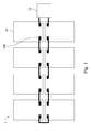
Fig. 1 is a schematic diagram of a solar power generation system according to an embodiment of the disclosure; -
Fig. 2 is a schematic diagram of a solar cell module inFig. 1 ; -
Fig. 3 is a partial schematic diagram of an embodiment of a first bridged solar cell and a second bridged solar cell inFig. 2 ; -
Fig. 4 is a partial sectional view of the first bridged solar cell and the second bridged solar cell along line 4-4' inFig. 3 ; -
Fig. 5 is a partial schematic diagram of a first bridged solar cell and a second bridged solar cell according to another embodiment of the disclosure; and -
Fig. 6 is a partial sectional view of the first bridged solar cell and the second bridged solar cell along line 6-6' inFig. 5 . - In which, reference signs are:
1: solar power generation system 10: solar cell module 10a: first solar cell string 10b: second solar cell string 100: first bridged solar cell 100a: substrate 100a1: front surface 100a2: back surface 100b: first set of bus bar electrodes 100c: second set of bus bar electrodes 100d: first welding member 100d1: coupling portion 100d2: terminal portion 100e: first insulation film 100e1: protruding portion 100f: second welding member 100f1: coupling portion 100f2: terminal portion 100g: third set of bus bar electrodes 100h: packaging member 102: first solar cell 104: second bridged solar cell 104a: another substrate 104a1: another front surface 106: second solar cell 108: junction box 300: first bridged solar cell 300a: substrate 300a1: front surface 300a2: back surface 300c: second set of bus bar electrodes 300d: first welding member 300d1: coupling portion 300d2: terminal portion 300e: first insulation film 300e1: protruding portion 300f: second welding member 300g: second insulation film 300h: third set of bus bar electrodes 300i: packaging member 304: second bridged solar cell 304a: another substrate 304a1: another front surface D1: first direction D2: second direction - Reference will now be made in detail to the present embodiments of the disclosure, examples of which are illustrated in the accompanying drawings. Wherever possible, the same reference numbers are used in the drawings and the description to refer to the same or like parts.
- An improved solar power generation system is provided. Particularly, the direction along which two sets of bus bar electrodes are disposed on a back surface of a bridged solar cell is different from the direction along which bus bar electrodes are disposed on a front surface of the bridged solar cell (e.g., the direction along which the sets of bus bar electrodes are disposed on the back surface of a bridged solar cell is perpendicular to the direction along which the bus bar electrodes are disposed on the front surface of the bridged solar cell). One set of bus bar electrodes on the back surface of a bridged solar cell of a solar cell string of a solar cell module can be directly extended onto a front surface of another bridged solar cell in another solar cell string of the solar cell module and act as the bus bar electrodes on the front surface of the another bridged solar cell when the solar cell strings are made to be electrically connected in series. Moreover, another set of bus bar electrodes on the back surface of the bridged solar cell of the solar cell string of the solar cell module can be electrically connected to another bridged solar cell in another solar cell module by using welding members and a junction box.
-
Fig. 1 is a schematic diagram of a solarpower generation system 1 according to an embodiment of the disclosure. - As shown in
Fig. 1 , the solarpower generation system 1 includes a plurality ofsolar cell modules 10 and aninverter 12. Thesolar cell modules 10 of the solarpower generation system 1 are arranged in two rows from theinverter 12 substantially along a direction. The positive and negative terminals of theinverter 12 of the solarpower generation system 1 are respectively connected to the two rows of thesolar cell modules 10, and the twosolar cell modules 10 farthest from theinverter 12 respectively in the two rows of thesolar cell modules 10 are coupled to each other so as to form a complete loop. Furthermore, each of thesolar cell modules 10 of the solarpower generation system 1 includesjunction boxes 108. Thejunction boxes 108 of any of thesolar cell modules 10 in each row of the solar cell modules 10 (excluding thesolar cell modules 10 at the ends of the rows) can be electrically connected to thejunction boxes 108 of thesolar cell modules 10 adjacent thereto. It is noted that thejunction boxes 108 of thesolar cell module 10 at the end of each row and adjacent to theinverter 12 are connected respectively to theinverter 12 and one of thejunction boxes 108 of the adjacentsolar cell module 10 in the same row, and thejunction boxes 108 of thesolar cell module 10 at the end of each row and farthest from theinverter 12 are connected respectively to one of thejunction boxes 108 of the adjacentsolar cell module 10 in the same row and to one of thejunction boxes 108 of the othersolar cell module 10 farthest from theinverter 12 in the adjacent row. -
Fig. 2 is a schematic diagram of asolar cell module 10 inFig. 1 .Fig. 3 is a partial schematic diagram of an embodiment of a first bridgedsolar cell 100 and a second bridgedsolar cell 104 inFig. 2 .Fig. 4 is a partial sectional view of the first bridgedsolar cell 100 and the second bridgedsolar cell 104 along line 4-4' inFig. 3 . - As shown in
Fig. 2 ,Fig. 3 , andFig. 4 , each of thesolar cell modules 10 includes a firstsolar cell string 10a. The firstsolar cell string 10a of thesolar cell module 10 includes a plurality of firstsolar cells 102 and at least one first bridged solar cell 100 (the firstsolar cell string 10a includes only one first bridgedsolar cell 100 in this embodiment). The firstsolar cells 102 of the firstsolar cell string 10a are electrically connected in series along a first direction D1, and the first bridgedsolar cell 100 is electrically connected to an end of the first solar cells 102 (i.e., the upper end of the firstsolar cells 102 shown inFig. 2 ). The first bridgedsolar cell 100 of thesolar cell module 10 includes asubstrate 100a, a first set ofbus bar electrodes 100b, a second set ofbus bar electrodes 100c, afirst welding member 100d, afirst insulation film 100e, a third set ofbus bar electrodes 100g, and asecond welding member 100f. Thesubstrate 100a of the first bridgedsolar cell 100 has a front surface 100a1 and a back surface 100a2. The first set ofbus bar electrodes 100b of the first bridgedsolar cell 100 is disposed on the front surface 100a1 of thesubstrate 100a along the first direction D1. The second set ofbus bar electrodes 100c of the first bridgedsolar cell 100 is disposed on the back surface 100a2 of thesubstrate 100a along a second direction D2 different from the first direction D1, and is electrically connected to the first set ofbus bar electrodes 100b via thesubstrate 100a. In the embodiment of the disclosure, the first direction D1 is perpendicular to the second direction D2, but the disclosure is not limited in this regard. - It should be pointed out that the reason why the
substrate 100 of the first bridgedsolar cell 100 can electrically interconnect the first set ofbus bar electrodes 100b and the second set ofbus bar electrodes 100c is that thesubstrate 100 includes an N-type semiconductor layer and a P-type semiconductor layer (not shown). In an embodiment of the disclosure, the N-type semiconductor layer of thesubstrate 100 is electrically connected to the first set ofbus bar electrodes 100b, and the P-type semiconductor layer of thesubstrate 100 is electrically connected to the second set ofbus bar electrodes 100c. The N-type semiconductor layer of thesubstrate 100 can be stimulated to emit free electrons after receiving light. Due to the potential difference, the free electrons flow to holes in the P-type semiconductor layer, thereby generating a current and thus electrically interconnecting the first set ofbus bar electrodes 100b and the second set ofbus bar electrodes 100c. - The
first welding member 100d of the first bridgedsolar cell 100 is electrically connected to the second set ofbus bar electrodes 100c. Thefirst insulation film 100e of the first bridgedsolar cell 100 is disposed on the back surface 100a2 of thesubstrate 100a. The third set ofbus bar electrodes 100g of the first bridgedsolar cell 100 is disposed on thefirst insulation film 100e along the second direction D2 so as to be insulated from thesubstrate 100a. Thesecond welding member 100f of the first bridgedsolar cell 100 is disposed on thefirst insulation film 100e and electrically connected to the third set ofbus bar electrodes 100g. - As shown in
Fig. 3 , thefirst welding member 100d of the first bridgedsolar cell 100 includes a coupling portion 100d1 and a terminal portion 100d2. The coupling portion 100d1 of thefirst welding member 100d is coupled to the second set ofbus bar electrodes 100c. The terminal portion 100d2 of thefirst welding member 100d is connected to the coupling portion 100d1. The coupling portion 100d1 and the terminal portion 100d2 of thefirst welding member 100d form an L-shaped structure, but the invention is not limited in this regard. Similarly, thesecond welding member 100f of the first bridgedsolar cell 100 includes a coupling portion 100f1 and a terminal portion 100f2. The coupling portion 100f1 of thesecond welding member 100f is coupled to the third set ofbus bar electrodes 100g. The terminal portion 100f2 of thesecond welding member 100f is connected to the coupling portion 100f1. The coupling portion 100f1 and the terminal portion 100f2 of thesecond welding member 100f form an L-shaped structure. With this configuration, thejunction box 108 of thesolar cell module 10 can be electrically connected to the terminal portion 100d2 of thefirst welding member 100d and the terminal portion 100f2 of thesecond welding member 100f, thereby electrically connecting to anotherjunction box 108 of another adjacentsolar cell module 10. - As shown in
Fig. 2 ,Fig. 3 , andFig. 4 , each of thesolar cell modules 10 further includes a secondsolar cell string 10b. The secondsolar cell string 10b of thesolar cell module 10 includes a plurality of secondsolar cells 106 and at least one second bridged solar cell 104 (the secondsolar cell string 10b includes only one second bridgedsolar cell 104 in this embodiment). The secondsolar cells 106 of the secondsolar cell string 10b are electrically connected in series along the first direction D1, and the second bridgedsolar cell 104 is electrically connected to an end of the second solar cells 106 (i.e., the upper end of the secondsolar cells 106 shown inFig. 2 ). The second bridgedsolar cell 104 of the secondsolar cell string 10b includes anothersubstrate 104a. Thesubstrate 104a of the second bridgedsolar cell 104 has another front surface 104a1. The third set ofbus bar electrodes 100g of the first bridgedsolar cell 100 is extended onto the front surface 104a1 of thesubstrate 104a of the second bridgedsolar cell 104 from the back surface 100a2 of thesubstrate 100a. Therefore, when the firstsolar cell string 10a and the secondsolar cell string 10b of thesolar cell module 10 are electrically connected to each other, the third set ofbus bar electrodes 100g of the first bridgedsolar cell 100 that is located on the back surface 100a2 of thesubstrate 100a are directly extended onto the another front surface 104a1 of the second bridgedsolar cell 104 of the secondsolar cell string 10b and act as the bus bar electrodes on the front surface 100a1 of the second bridgedsolar cell 104. - In other words, the third set of
bus bar electrodes 100g is shared by the first bridgedsolar cell 100 and the second bridgedsolar cell 104, and is electrically connected to the back surface 100a2 of thesubstrate 100a of the first bridgedsolar cell 100 and the front surface 104a1 of thesubstrate 104a of the second bridgedsolar cell 104. Although the third set ofbus bar electrodes 100g is described as a component included in the first bridgedsolar cell 100 above, the third set ofbus bar electrodes 100g can also be regarded as a component included in the second bridgedsolar cell 104. - It can be seen that the solar
power generation system 1 of the disclosure does not need to utilize a region adjacent to an upper edge and a region adjacent to a lower edge of a glass substrate (not shown) of each of thesolar cell modules 10 for electrical connection by using bussing ribbons. Accordingly, not only can the total area of the glass substrates of thesolar cell modules 10 be reduced, but the total length of the bussing ribbons used in thesolar cell modules 10 can also be reduced, so as to achieve the advantages of saving costs of related materials and reducing energy loss. For example, because bussing ribbons need to be installed in the regions respectively adjacent to the upper and lower edges of a glass substrate of a conventional solar cell module, the length and width of the glass substrate of the conventional solar cell module are respectively 1668 mm and 1000 mm. In contrast, bussing ribbons for electrical connection are unnecessary in thesolar cell module 10 of the disclosure, and so the length and width of the glass substrate used in thesolar cell module 10 can be reduced to 1611 mm and 983 mm respectively. - As shown in
Fig. 4 , the first bridgedsolar cell 100 of the firstsolar cell string 10a further includes apackaging member 100h adhered under thefirst insulation film 100e and located between thefirst insulation film 100e and the back surface 100a2 of thesubstrate 100a. Thefirst insulation film 100e of the first bridgedsolar cell 100 has a protruding portion 100e1. The protruding portion 100e1 of thefirst insulation film 100e protrudes outwardly from an edge of the back surface 100a2 of thesubstrate 100a. The third set ofbus bar electrodes 100g of the first bridgedsolar cell 100 is extended away from thefirst insulation film 100e from the protruding portion 100e1, and is extended onto the front surface 104a1 of thesubstrate 104a of the second bridgedsolar cell 104. Accordingly, the third set ofbus bar electrodes 100g are prevented from directly contacting thesubstrate 100a by the protruding portion 100e1 of thefirst insulation film 100e, thereby preventing the third set ofbus bar electrodes 100g from being electrically connected to thesubstrate 100a. - In an embodiment of the disclosure, the
junction boxes 108 of each of thesolar cell modules 10 are disposed on the back surface 100a2 of thesubstrate 100a of the first bridgedsolar cell 100, but the disclosure is not limited in this regard. -
Fig. 5 is a partial schematic diagram of a first bridgedsolar cell 300 and a second bridgedsolar cell 304 according to another embodiment of the disclosure.Fig. 6 is a partial sectional view of the first bridgedsolar cell 300 and the second bridgedsolar cell 304 along line 6-6' inFig. 5 . - As shown in
Fig. 5 andFig. 6 , the first bridgedsolar cell 300 includes asubstrate 300a, a first set of bus bar electrodes (seeFig. 2 ), a second set ofbus bar electrodes 300c, afirst welding member 300d, afirst insulation film 300e, a third set ofbus bar electrodes 300h, asecond welding member 300f, and apackaging member 300i. The first set of bus bar electrodes of the first bridgedsolar cell 300 is disposed on a front surface 300a1 of thesubstrate 300a along the first direction D1 (seeFig. 2 ). The second set ofbus bar electrodes 300c of the first bridgedsolar cell 300 is disposed on a back surface 300a2 of thesubstrate 300a along the second direction D2 different from the first direction D1 and electrically connected to the first set of bus bar electrodes via thesubstrate 300a (seeFig. 2 ). Thefirst welding member 300d of the first bridgedsolar cell 300 is electrically connected to the second set ofbus bar electrodes 300c. Thefirst insulation film 300e of the first bridgedsolar cell 300 is disposed on the back surface 300a2 of thesubstrate 300a. The third set ofbus bar electrodes 300h of the first bridgedsolar cell 300 is disposed on thefirst insulation film 300e along the second direction D2 so as to be insulated from thesubstrate 300a. Thepackaging member 300i of the first bridgedsolar cell 300 is adhered under thefirst insulation film 300e and located between thefirst insulation film 300e and the back surface 300a2 of thesubstrate 300a. Thefirst insulation film 300e of the first bridgedsolar cell 300 has a protruding portion 300e1. The protruding portion 300e1 of thefirst insulation film 300e protrudes outwardly from an edge of the back surface 300a2 of thesubstrate 300a. The third set ofbus bar electrodes 300h of the first bridgedsolar cell 300 is extended away from thefirst insulation film 300e from the protruding portion 300e1, and is extended onto another front surface 304a1 of anothersubstrate 304a of the second bridgedsolar cell 304. - Accordingly, the first bridged
solar cell 300 can prevent the third set ofbus bar electrodes 300h from directly contacting thesubstrate 300a by the protruding portion 300e1 of thefirst insulation film 300e, thereby preventing the third set ofbus bar electrodes 300h from being electrically connected to thesubstrate 300a. Thesecond welding member 300f of the first bridgedsolar cell 300 is disposed on thefirst insulation film 300e and electrically connected to the third set ofbus bar electrodes 300h. - As shown in
Fig. 5 , thefirst welding member 300d of the first bridgedsolar cell 300 includes a coupling portion 300d1 and a terminal portion 300d2. The coupling portion 300d1 of thefirst welding member 300d is coupled to the second set ofbus bar electrodes 300c. The terminal portion 300d2 of thefirst welding member 300d is connected to the coupling portion 300d1. The coupling portion 300d1 and the terminal portion 300d2 of thefirst welding member 300d form a T-shaped structure, but the invention is not limited in this regard. Similarly, thesecond welding member 300f of the first bridgedsolar cell 300 includes a coupling portion 300f1 and a terminal portion 300f2. The coupling portion 300f1 of thesecond welding member 300f is coupled to the third set ofbus bar electrodes 300h. The terminal portion 300f2 of thesecond welding member 300f is connected to the coupling portion. The coupling portion 300f1 and the terminal portion 300f2 of thesecond welding member 300f form a T-shaped structure. Therefore, thejunction box 108 of thesolar cell module 10 can be electrically connected to the terminal portion 300d2 of thefirst welding member 300d and the terminal portion 300f2 of thesecond welding member 300f, thereby electrically connecting to anotherjunction box 108 of another adjacentsolar cell module 10. - It should be pointed out that assembly workers pass the terminal portion 300d2 of the
first welding member 300d and the terminal portion 300f2 of thesecond welding member 300f through a back sheet (not shown) before electrically connecting to thejunction box 108. As shown inFig. 5 , the terminal portion 300d2 of thefirst welding member 300d and the terminal portion 300f2 of thesecond welding member 300f face the same direction (i.e., to the right inFig. 5 ). In contrast, as shown inFig. 3 , the terminal portion 100d2 of thefirst welding member 100d and the terminal portion 100f2 of thesecond welding member 100f face different directions (i.e., the terminal portion 100d2 faces the right and the terminal portion 100f2 faces the left inFig. 3 ). Compared with the embodiment inFig. 3 , assembly workers can realize smoother assembly during the process of passing the terminal portion 300d2 and the terminal portion 300f2 through the back sheet due to the fact that these elements face the same direction, as described above. In other words, the advantage of the terminal portion 300d2 and the terminal portion 300f2 facing the same direction is that convenience during assembly may be realized. - Furthermore, in the embodiment of the disclosure, the first bridged
solar cell 300 further includes asecond insulation film 300g. Thesecond insulation film 300g of the first bridgedsolar cell 300 is disposed on thefirst insulation film 300e and covers a portion of thesecond welding member 300f (the central part of the coupling portion 300f1 of thesecond welding member 300f inFig. 5 ). A portion of thefirst welding member 300d (the end part of the terminal portion of thesecond welding member 300f inFig. 5 ) of the first bridgedsolar cell 300 is extended onto thesecond insulation film 300g and insulated from thesecond welding member 300f by thesecond insulation film 300g. Furthermore, the portion of thefirst welding member 300d of the first bridgedsolar cell 300 extended onto thesecond insulation film 300g (i.e., the end part of the terminal portion of thesecond welding member 300f inFig. 5 ) and the portion of thesecond welding member 300f covered by thesecond insulation film 300g (i.e., the central part of the coupling portion 300f1 of thesecond welding member 300f inFig. 5 ) are respectively located at two opposite surfaces of thesecond insulation film 300g. With the foregoing layout, the distance between the terminal portion 300d2 of thefirst welding member 300d and the terminal portion 300f2 of thesecond welding member 300f can be reduced. Therefore, each of thesolar cell modules 10 in the solarpower generation system 1 of the disclosure can adopt small-sized junction boxes, thereby reducing the overall costs of the solarpower generation system 1. - In another embodiment of the disclosure, the foregoing
second insulation film 300g can be omitted from the configuration of the first bridgedsolar cell 300. As long as the terminal portion 300d2 of thefirst welding member 300d does not contact the terminal portion 300f2 of thesecond welding member 300, the purpose of adopting small-sized junction boxes 108 can also be achieved by appropriately adjusting the shapes of the terminal portion 300d2 and the terminal portion 300f2 to reduce the distance between the terminal portion 300d2 and the terminal portion 300f2. - According to the foregoing recitations of the embodiments of the disclosure, it can be seen that a bridged solar cell used in a solar power generation system is such that the direction along which bus bar electrodes are disposed on a back surface (which is referred to also as a shadow-side surface in the disclosure) of the bridged solar cell is different from the direction along which bus bar electrodes are disposed on a front surface (which is referred to also as an incident light-side surface in the disclosure) of the bridged solar cell (e.g., the direction along which two sets of bus bar electrodes are disposed on the back surface of a bridged solar cell is made to be perpendicular to the direction along which the bus bar electrodes are disposed on the front surface of the bridged solar cell). Therefore, one set of bus bar electrodes on the back surface of a bridged solar cell of a solar cell string of a solar cell module can be directly extended onto a front surface of another bridged solar cell in another solar cell string of the solar cell module and act as the bus bar electrodes on the front surface of the another bridged solar cell when the solar cell strings are made to be electrically connected in series. Moreover, another set of bus bar electrodes on the back surface of the bridged solar cell of the solar cell string of the solar cell module can be electrically connected to another bridged solar cell in another solar cell module by using welding members and a junction box. Accordingly, not only can the area of the glass substrate of the solar cell module be reduced, but the total length of the used bussing ribbons in the solar cell module can also be reduced, so as to achieve the advantages of saving costs of related materials and minimizing energy loss.
- It will be apparent to those skilled in the art that various modifications and variations can be made to the structure of the present disclosure without departing from the scope or spirit of the disclosure. In view of the foregoing, it is intended that the present disclosure cover modifications and variations of this disclosure provided they fall within the scope of the following claims.
- A bridged solar cell provided by the disclosure can be used to electrically connect two solar cell strings in a solar cell module. The bus bar electrodes on the back surface of the bridged solar cell can be directly extended onto a front surface of another bridged solar cell in another solar cell string and act as the bus bar electrodes on the front surface of the another bridged solar cell, and so it is unnecessary to electrically connect the solar cell module to an external element (i.e., to another solar cell module) using bussing ribbons disposed at a region adjacent to an upper edge and a region adjacent to a lower edge of a glass substrate of the solar cell module. Accordingly, not only can the area of the glass substrate of the solar cell module be reduced, but the total length of the used bussing ribbons in the solar cell module can also be reduced, so as to achieve the advantages of saving costs of related materials and minimizing energy loss.
Claims (14)
- A bridged solar cell characterized by comprising:a substrate having a front surface and a back surface;a first set of bus bar electrodes disposed on the front surface along a first direction;a second set of bus bar electrodes disposed on the back surface along a second direction different from the first direction and electrically connected to the first set of bus bar electrodes via the substrate;a first welding member electrically connected to the second set of bus bar electrodes;a first insulation film disposed on the back surface;a third set of bus bar electrodes disposed on the first insulation film along the second direction so as to be insulated from the substrate; anda second welding member disposed on the first insulation film and electrically connected to the third set of bus bar electrodes.
- The bridged solar cell of claim 1, characterized by further comprising a second insulation film disposed on the first insulation film and covering a portion of the second welding member, wherein a portion of the first welding member is extended onto the second insulation film and insulated from the second welding member by the second insulation film.
- The bridged solar cell of claim 2, characterized in that wherein the portion of the first welding member extended onto the second insulation film and the portion of the second welding member covered by the second insulation film are respectively located at two opposite surfaces of the second insulation film.
- The bridged solar cell of claim 1, characterized in that wherein the first insulation film has a protruding portion protruding outwardly from an edge of the back surface, and the third set of bus bar electrodes is extended away from the first insulation film from the protruding portion.
- The bridged solar cell of claim 1, characterized in that wherein the first welding member comprises:a coupling portion coupled to the second set of bus bar electrodes; anda terminal portion connected to the coupling portion, wherein the coupling portion and the terminal portion form an L-shaped structure or a T-shaped structure.
- The bridged solar cell of claim 1, characterized in that wherein the second welding member comprises:a coupling portion coupled to the third set of bus bar electrodes; anda terminal portion connected to the coupling portion, wherein the coupling portion and the terminal portion form an L-shaped structure or a T-shaped structure.
- A solar power generation system characterized by comprising a plurality of solar cell modules, wherein each of the solar cell modules comprises:a first solar cell string and a junction box;
the first solar cell string comprising a plurality of first solar cells and a first bridged solar cell that are connected in series along a first direction, wherein the first bridged solar cell comprises:a substrate having a front surface and a back surface;a first set of bus bar electrodes disposed on the front surface along the first direction;a second set of bus bar electrodes disposed on the back surface along a second direction different from the first direction and electrically connected to the first set of bus bar electrodes via the substrate;a first welding member electrically connected to the second set of bus bar electrodes;a first insulation film disposed on the back surface;a third set of bus bar electrodes disposed on the first insulation film along the second direction so as to be insulated from the substrate; anda second welding member disposed on the first insulation film and electrically connected to the third set of bus bar electrodes; andthe junction box electrically connected to the first welding member and the second welding member;
wherein the junction box of each of the solar cell modules is electrically connected to another junction box of another adjacent solar cell module. - The solar power generation system of claim 7, characterized in that wherein each of the solar cell modules further comprises a second solar cell string, the second solar cell string comprises a plurality of second solar cells and a second bridged solar cell that are connected in series, the second bridged solar cell comprises a substrate, the substrate of the second bridged solar cell has a front surface, and the third set of bus bar electrodes is extended onto the front surface of the substrate of the second bridged solar cell.
- The solar power generation system of claim 7, characterized by further comprising a second insulation film disposed on the first insulation film and covering a portion of the second welding member, wherein a portion of the first welding member is extended onto the second insulation film and insulated from the second welding member by the second insulation film.
- The solar power generation system of claim 9, characterized in that wherein the portion of the first welding member extended onto the second insulation film and the portion of the second welding member covered by the second insulation film are respectively located at two opposite surfaces of the second insulation film.
- The solar power generation system of claim 7, characterized in that wherein the first insulation film has a protruding portion protruding outwardly from an edge of the back surface, and the third set of bus bar electrodes is extended away from the first insulation film from the protruding portion.
- The solar power generation system of claim 7, characterized in that wherein the first welding member comprises:a coupling portion coupled to the second set of bus bar electrodes; anda terminal portion connected to the coupling portion, wherein the coupling portion and the terminal portion form an L-shaped structure or a T-shaped structure.
- The solar power generation system of claim 7, characterized in that wherein the second welding member comprises:a coupling portion coupled to the third set of bus bar electrodes; anda terminal portion connected to the coupling portion, wherein the coupling portion and the terminal portion form an L-shaped structure or a T-shaped structure.
- The solar power generation system of claim 7, characterized in that wherein the junction box is disposed on the back surface.
Applications Claiming Priority (2)
| Application Number | Priority Date | Filing Date | Title |
|---|---|---|---|
| CN201210165275.1A CN102769059B (en) | 2012-05-24 | 2012-05-24 | Bridging solar cells and solar power generation systems |
| PCT/CN2012/076752 WO2013174048A1 (en) | 2012-05-24 | 2012-06-12 | Bridged solar cell and solar power generation system |
Publications (3)
| Publication Number | Publication Date |
|---|---|
| EP2858124A1 true EP2858124A1 (en) | 2015-04-08 |
| EP2858124A4 EP2858124A4 (en) | 2016-02-24 |
| EP2858124B1 EP2858124B1 (en) | 2019-09-18 |
Family
ID=47096378
Family Applications (1)
| Application Number | Title | Priority Date | Filing Date |
|---|---|---|---|
| EP12877403.1A Active EP2858124B1 (en) | 2012-05-24 | 2012-06-12 | Bridged solar cell and solar power generation system |
Country Status (5)
| Country | Link |
|---|---|
| US (1) | US8829338B2 (en) |
| EP (1) | EP2858124B1 (en) |
| CN (1) | CN102769059B (en) |
| TW (1) | TWI472045B (en) |
| WO (1) | WO2013174048A1 (en) |
Cited By (1)
| Publication number | Priority date | Publication date | Assignee | Title |
|---|---|---|---|---|
| CN108735845A (en) * | 2018-07-16 | 2018-11-02 | 宁波尤利卡太阳能科技发展有限公司 | A kind of solar energy slice battery |
Families Citing this family (8)
| Publication number | Priority date | Publication date | Assignee | Title |
|---|---|---|---|---|
| US9444004B1 (en) * | 2014-05-02 | 2016-09-13 | Deployable Space Systems, Inc. | System and method for producing modular photovoltaic panel assemblies for space solar arrays |
| CN104282788B (en) * | 2014-09-28 | 2017-03-22 | 苏州中来光伏新材股份有限公司 | Main-grid-free high-efficiency back contact solar cell module, main-grid-free high-efficiency back contact solar cell assembly and manufacturing technology of main-grid-free high-efficiency back contact solar cell assembly |
| DE102015009004A1 (en) | 2015-06-05 | 2016-12-08 | Solaero Technologies Corp. | Automated arrangement and mounting of solar cells on panels for space applications |
| US10276742B2 (en) | 2015-07-09 | 2019-04-30 | Solaero Technologies Corp. | Assembly and mounting of solar cells on space vehicles or satellites |
| CN109962677B (en) * | 2017-12-14 | 2024-07-23 | 阿特斯阳光电力集团股份有限公司 | Photovoltaic module |
| CN108231952B (en) * | 2017-12-29 | 2020-06-12 | 杭州瞩日能源科技有限公司 | Photovoltaic cell module and its preparation process |
| CN110380684A (en) * | 2018-04-13 | 2019-10-25 | 北京汉能光伏投资有限公司 | Bridging part and its detection method, solar battery splicing apparatus |
| CN111276549B (en) | 2018-11-20 | 2021-03-09 | 成都晔凡科技有限公司 | Battery piece for laminated assembly, laminated assembly and method for preparing battery piece |
Family Cites Families (14)
| Publication number | Priority date | Publication date | Assignee | Title |
|---|---|---|---|---|
| US4513167A (en) * | 1982-04-27 | 1985-04-23 | The Australian National University | Arrays of polarized energy-generating elements |
| US8440907B2 (en) * | 2006-04-14 | 2013-05-14 | Sharp Kabushiki Kaisha | Solar cell, solar cell string and solar cell module |
| JP5153097B2 (en) * | 2006-07-31 | 2013-02-27 | 三洋電機株式会社 | Solar cell module |
| DE102007035883A1 (en) * | 2007-07-31 | 2009-02-12 | Institut Für Solarenergieforschung Gmbh | Solar module, has rear contact solar cells arranged at distance along translation direction, where contact surface is not overlapped with another contact surface when former surface is shifted to distance in translation direction |
| JP5147672B2 (en) * | 2008-01-31 | 2013-02-20 | 三洋電機株式会社 | Solar cell module and method for manufacturing solar cell module |
| EP2253023B2 (en) | 2008-03-11 | 2022-11-09 | (CNBM) Bengbu Design & Research Institute for Glass Industry Co., Ltd. | Solar module |
| CN102113130A (en) | 2008-04-29 | 2011-06-29 | 应用材料股份有限公司 | Photovoltaic modules manufactured using monolithic module combination technology |
| DE102009005168A1 (en) * | 2009-01-14 | 2010-07-22 | Fraunhofer-Gesellschaft zur Förderung der angewandten Forschung e.V. | Solar cell and method for producing a solar cell from a silicon substrate |
| US8829333B2 (en) * | 2010-02-24 | 2014-09-09 | Kyocera Corporation | Solar cell module and method for manufacturing same |
| CN201655819U (en) * | 2010-02-25 | 2010-11-24 | 埃孚光伏制造有限公司 | Solar cell assembling structure |
| JP2012023136A (en) * | 2010-07-13 | 2012-02-02 | Mitsubishi Electric Corp | Solar cell module and method of manufacturing the same |
| CN101980370B (en) * | 2010-08-31 | 2012-09-26 | 深圳市创益科技发展有限公司 | Frameless solar battery component and encapsulation method |
| CN102005493B (en) * | 2010-09-29 | 2012-10-03 | 上海晶澳太阳能科技有限公司 | Solar photovoltaic assembly |
| TWI458104B (en) * | 2011-09-14 | 2014-10-21 | Au Optronics Corp | Solar battery module |
-
2012
- 2012-05-24 CN CN201210165275.1A patent/CN102769059B/en active Active
- 2012-06-12 EP EP12877403.1A patent/EP2858124B1/en active Active
- 2012-06-12 WO PCT/CN2012/076752 patent/WO2013174048A1/en not_active Ceased
- 2012-07-16 TW TW101125560A patent/TWI472045B/en active
- 2012-10-24 US US13/659,114 patent/US8829338B2/en active Active
Cited By (1)
| Publication number | Priority date | Publication date | Assignee | Title |
|---|---|---|---|---|
| CN108735845A (en) * | 2018-07-16 | 2018-11-02 | 宁波尤利卡太阳能科技发展有限公司 | A kind of solar energy slice battery |
Also Published As
| Publication number | Publication date |
|---|---|
| CN102769059A (en) | 2012-11-07 |
| US20130312807A1 (en) | 2013-11-28 |
| EP2858124A4 (en) | 2016-02-24 |
| TW201349525A (en) | 2013-12-01 |
| TWI472045B (en) | 2015-02-01 |
| CN102769059B (en) | 2015-08-05 |
| US8829338B2 (en) | 2014-09-09 |
| EP2858124B1 (en) | 2019-09-18 |
| WO2013174048A1 (en) | 2013-11-28 |
Similar Documents
| Publication | Publication Date | Title |
|---|---|---|
| EP2858124B1 (en) | Bridged solar cell and solar power generation system | |
| US20090126788A1 (en) | Solar cell and solar cell module including the same | |
| US20140053890A1 (en) | Photovoltaic apparatus | |
| ES2753501T3 (en) | Arrays of solar panels and diode cables | |
| EP2610916A2 (en) | Bifacial solar cell module | |
| KR101747339B1 (en) | Solar cell module | |
| US20170194900A1 (en) | Methods for mounting a junction box on a glass solar module with cutout | |
| US20140174507A1 (en) | Apparatus for photovoltaic power generation | |
| WO2012090849A1 (en) | Solar cell string and solar cell module | |
| US9972726B2 (en) | Photovoltaic apparatus | |
| CN205039772U (en) | Solar cell module | |
| JP2006216608A (en) | Solar cell module | |
| CN220087251U (en) | Junction box system for multi-junction photovoltaic cell assembly based on perovskite structure | |
| KR102145756B1 (en) | Leakage current reduction bipv module | |
| JP5916605B2 (en) | Solar power plant | |
| KR20230093447A (en) | solar module | |
| CN108666373A (en) | Photovoltaic modules | |
| CN117997265A (en) | Intelligent junction box system for multi-junction photovoltaic module based on perovskite structure | |
| CN112290884A (en) | Series-type integrated split type photovoltaic module junction box and photovoltaic module | |
| US20230207714A1 (en) | Solar cell | |
| WO2015041463A1 (en) | Solar battery module | |
| WO2015053565A1 (en) | Solar cell module | |
| CN116779702A (en) | Photovoltaic modules and photovoltaic systems | |
| US9685574B2 (en) | Solar cell module | |
| KR101721360B1 (en) | Solar cell module and array |
Legal Events
| Date | Code | Title | Description |
|---|---|---|---|
| PUAI | Public reference made under article 153(3) epc to a published international application that has entered the european phase |
Free format text: ORIGINAL CODE: 0009012 |
|
| 17P | Request for examination filed |
Effective date: 20141020 |
|
| AK | Designated contracting states |
Kind code of ref document: A1 Designated state(s): AL AT BE BG CH CY CZ DE DK EE ES FI FR GB GR HR HU IE IS IT LI LT LU LV MC MK MT NL NO PL PT RO RS SE SI SK SM TR |
|
| AX | Request for extension of the european patent |
Extension state: BA ME |
|
| RIN1 | Information on inventor provided before grant (corrected) |
Inventor name: TSENG, HUANGCHI Inventor name: YANG, CHUNMING |
|
| DAX | Request for extension of the european patent (deleted) | ||
| RA4 | Supplementary search report drawn up and despatched (corrected) |
Effective date: 20160127 |
|
| RIC1 | Information provided on ipc code assigned before grant |
Ipc: H01L 31/05 20060101AFI20160121BHEP Ipc: H01L 31/068 20120101ALI20160121BHEP Ipc: H01L 31/02 20060101ALI20160121BHEP |
|
| STAA | Information on the status of an ep patent application or granted ep patent |
Free format text: STATUS: EXAMINATION IS IN PROGRESS |
|
| 17Q | First examination report despatched |
Effective date: 20170807 |
|
| REG | Reference to a national code |
Ref country code: DE Ref legal event code: R079 Ref document number: 602012064227 Country of ref document: DE Free format text: PREVIOUS MAIN CLASS: H01L0031050000 Ipc: H02S0040360000 |
|
| RIC1 | Information provided on ipc code assigned before grant |
Ipc: H01L 31/05 20140101ALI20190213BHEP Ipc: H01L 31/02 20060101ALI20190213BHEP Ipc: H02S 40/36 20140101AFI20190213BHEP |
|
| GRAP | Despatch of communication of intention to grant a patent |
Free format text: ORIGINAL CODE: EPIDOSNIGR1 |
|
| STAA | Information on the status of an ep patent application or granted ep patent |
Free format text: STATUS: GRANT OF PATENT IS INTENDED |
|
| INTG | Intention to grant announced |
Effective date: 20190326 |
|
| GRAS | Grant fee paid |
Free format text: ORIGINAL CODE: EPIDOSNIGR3 |
|
| GRAA | (expected) grant |
Free format text: ORIGINAL CODE: 0009210 |
|
| STAA | Information on the status of an ep patent application or granted ep patent |
Free format text: STATUS: THE PATENT HAS BEEN GRANTED |
|
| AK | Designated contracting states |
Kind code of ref document: B1 Designated state(s): AL AT BE BG CH CY CZ DE DK EE ES FI FR GB GR HR HU IE IS IT LI LT LU LV MC MK MT NL NO PL PT RO RS SE SI SK SM TR |
|
| REG | Reference to a national code |
Ref country code: GB Ref legal event code: FG4D |
|
| REG | Reference to a national code |
Ref country code: CH Ref legal event code: EP |
|
| REG | Reference to a national code |
Ref country code: DE Ref legal event code: R096 Ref document number: 602012064227 Country of ref document: DE |
|
| REG | Reference to a national code |
Ref country code: AT Ref legal event code: REF Ref document number: 1182507 Country of ref document: AT Kind code of ref document: T Effective date: 20191015 |
|
| REG | Reference to a national code |
Ref country code: IE Ref legal event code: FG4D |
|
| REG | Reference to a national code |
Ref country code: NL Ref legal event code: MP Effective date: 20190918 |
|
| PG25 | Lapsed in a contracting state [announced via postgrant information from national office to epo] |
Ref country code: FI Free format text: LAPSE BECAUSE OF FAILURE TO SUBMIT A TRANSLATION OF THE DESCRIPTION OR TO PAY THE FEE WITHIN THE PRESCRIBED TIME-LIMIT Effective date: 20190918 Ref country code: HR Free format text: LAPSE BECAUSE OF FAILURE TO SUBMIT A TRANSLATION OF THE DESCRIPTION OR TO PAY THE FEE WITHIN THE PRESCRIBED TIME-LIMIT Effective date: 20190918 Ref country code: SE Free format text: LAPSE BECAUSE OF FAILURE TO SUBMIT A TRANSLATION OF THE DESCRIPTION OR TO PAY THE FEE WITHIN THE PRESCRIBED TIME-LIMIT Effective date: 20190918 Ref country code: BG Free format text: LAPSE BECAUSE OF FAILURE TO SUBMIT A TRANSLATION OF THE DESCRIPTION OR TO PAY THE FEE WITHIN THE PRESCRIBED TIME-LIMIT Effective date: 20191218 Ref country code: LT Free format text: LAPSE BECAUSE OF FAILURE TO SUBMIT A TRANSLATION OF THE DESCRIPTION OR TO PAY THE FEE WITHIN THE PRESCRIBED TIME-LIMIT Effective date: 20190918 Ref country code: NO Free format text: LAPSE BECAUSE OF FAILURE TO SUBMIT A TRANSLATION OF THE DESCRIPTION OR TO PAY THE FEE WITHIN THE PRESCRIBED TIME-LIMIT Effective date: 20191218 |
|
| REG | Reference to a national code |
Ref country code: LT Ref legal event code: MG4D |
|
| PG25 | Lapsed in a contracting state [announced via postgrant information from national office to epo] |
Ref country code: LV Free format text: LAPSE BECAUSE OF FAILURE TO SUBMIT A TRANSLATION OF THE DESCRIPTION OR TO PAY THE FEE WITHIN THE PRESCRIBED TIME-LIMIT Effective date: 20190918 Ref country code: AL Free format text: LAPSE BECAUSE OF FAILURE TO SUBMIT A TRANSLATION OF THE DESCRIPTION OR TO PAY THE FEE WITHIN THE PRESCRIBED TIME-LIMIT Effective date: 20190918 Ref country code: RS Free format text: LAPSE BECAUSE OF FAILURE TO SUBMIT A TRANSLATION OF THE DESCRIPTION OR TO PAY THE FEE WITHIN THE PRESCRIBED TIME-LIMIT Effective date: 20190918 Ref country code: GR Free format text: LAPSE BECAUSE OF FAILURE TO SUBMIT A TRANSLATION OF THE DESCRIPTION OR TO PAY THE FEE WITHIN THE PRESCRIBED TIME-LIMIT Effective date: 20191219 |
|
| REG | Reference to a national code |
Ref country code: AT Ref legal event code: MK05 Ref document number: 1182507 Country of ref document: AT Kind code of ref document: T Effective date: 20190918 |
|
| PG25 | Lapsed in a contracting state [announced via postgrant information from national office to epo] |
Ref country code: IT Free format text: LAPSE BECAUSE OF FAILURE TO SUBMIT A TRANSLATION OF THE DESCRIPTION OR TO PAY THE FEE WITHIN THE PRESCRIBED TIME-LIMIT Effective date: 20190918 Ref country code: EE Free format text: LAPSE BECAUSE OF FAILURE TO SUBMIT A TRANSLATION OF THE DESCRIPTION OR TO PAY THE FEE WITHIN THE PRESCRIBED TIME-LIMIT Effective date: 20190918 Ref country code: PL Free format text: LAPSE BECAUSE OF FAILURE TO SUBMIT A TRANSLATION OF THE DESCRIPTION OR TO PAY THE FEE WITHIN THE PRESCRIBED TIME-LIMIT Effective date: 20190918 Ref country code: AT Free format text: LAPSE BECAUSE OF FAILURE TO SUBMIT A TRANSLATION OF THE DESCRIPTION OR TO PAY THE FEE WITHIN THE PRESCRIBED TIME-LIMIT Effective date: 20190918 Ref country code: NL Free format text: LAPSE BECAUSE OF FAILURE TO SUBMIT A TRANSLATION OF THE DESCRIPTION OR TO PAY THE FEE WITHIN THE PRESCRIBED TIME-LIMIT Effective date: 20190918 Ref country code: RO Free format text: LAPSE BECAUSE OF FAILURE TO SUBMIT A TRANSLATION OF THE DESCRIPTION OR TO PAY THE FEE WITHIN THE PRESCRIBED TIME-LIMIT Effective date: 20190918 Ref country code: ES Free format text: LAPSE BECAUSE OF FAILURE TO SUBMIT A TRANSLATION OF THE DESCRIPTION OR TO PAY THE FEE WITHIN THE PRESCRIBED TIME-LIMIT Effective date: 20190918 Ref country code: PT Free format text: LAPSE BECAUSE OF FAILURE TO SUBMIT A TRANSLATION OF THE DESCRIPTION OR TO PAY THE FEE WITHIN THE PRESCRIBED TIME-LIMIT Effective date: 20200120 |
|
| PG25 | Lapsed in a contracting state [announced via postgrant information from national office to epo] |
Ref country code: CZ Free format text: LAPSE BECAUSE OF FAILURE TO SUBMIT A TRANSLATION OF THE DESCRIPTION OR TO PAY THE FEE WITHIN THE PRESCRIBED TIME-LIMIT Effective date: 20190918 Ref country code: SK Free format text: LAPSE BECAUSE OF FAILURE TO SUBMIT A TRANSLATION OF THE DESCRIPTION OR TO PAY THE FEE WITHIN THE PRESCRIBED TIME-LIMIT Effective date: 20190918 Ref country code: SM Free format text: LAPSE BECAUSE OF FAILURE TO SUBMIT A TRANSLATION OF THE DESCRIPTION OR TO PAY THE FEE WITHIN THE PRESCRIBED TIME-LIMIT Effective date: 20190918 Ref country code: IS Free format text: LAPSE BECAUSE OF FAILURE TO SUBMIT A TRANSLATION OF THE DESCRIPTION OR TO PAY THE FEE WITHIN THE PRESCRIBED TIME-LIMIT Effective date: 20200224 |
|
| REG | Reference to a national code |
Ref country code: DE Ref legal event code: R097 Ref document number: 602012064227 Country of ref document: DE |
|
| PLBE | No opposition filed within time limit |
Free format text: ORIGINAL CODE: 0009261 |
|
| STAA | Information on the status of an ep patent application or granted ep patent |
Free format text: STATUS: NO OPPOSITION FILED WITHIN TIME LIMIT |
|
| PG2D | Information on lapse in contracting state deleted |
Ref country code: IS |
|
| PG25 | Lapsed in a contracting state [announced via postgrant information from national office to epo] |
Ref country code: DK Free format text: LAPSE BECAUSE OF FAILURE TO SUBMIT A TRANSLATION OF THE DESCRIPTION OR TO PAY THE FEE WITHIN THE PRESCRIBED TIME-LIMIT Effective date: 20190918 Ref country code: IS Free format text: LAPSE BECAUSE OF FAILURE TO SUBMIT A TRANSLATION OF THE DESCRIPTION OR TO PAY THE FEE WITHIN THE PRESCRIBED TIME-LIMIT Effective date: 20200119 |
|
| 26N | No opposition filed |
Effective date: 20200619 |
|
| PG25 | Lapsed in a contracting state [announced via postgrant information from national office to epo] |
Ref country code: SI Free format text: LAPSE BECAUSE OF FAILURE TO SUBMIT A TRANSLATION OF THE DESCRIPTION OR TO PAY THE FEE WITHIN THE PRESCRIBED TIME-LIMIT Effective date: 20190918 |
|
| PG25 | Lapsed in a contracting state [announced via postgrant information from national office to epo] |
Ref country code: MC Free format text: LAPSE BECAUSE OF FAILURE TO SUBMIT A TRANSLATION OF THE DESCRIPTION OR TO PAY THE FEE WITHIN THE PRESCRIBED TIME-LIMIT Effective date: 20190918 |
|
| REG | Reference to a national code |
Ref country code: CH Ref legal event code: PL |
|
| PG25 | Lapsed in a contracting state [announced via postgrant information from national office to epo] |
Ref country code: LU Free format text: LAPSE BECAUSE OF NON-PAYMENT OF DUE FEES Effective date: 20200612 |
|
| REG | Reference to a national code |
Ref country code: BE Ref legal event code: MM Effective date: 20200630 |
|
| PG25 | Lapsed in a contracting state [announced via postgrant information from national office to epo] |
Ref country code: FR Free format text: LAPSE BECAUSE OF NON-PAYMENT OF DUE FEES Effective date: 20200630 Ref country code: CH Free format text: LAPSE BECAUSE OF NON-PAYMENT OF DUE FEES Effective date: 20200630 Ref country code: LI Free format text: LAPSE BECAUSE OF NON-PAYMENT OF DUE FEES Effective date: 20200630 Ref country code: IE Free format text: LAPSE BECAUSE OF NON-PAYMENT OF DUE FEES Effective date: 20200612 |
|
| PG25 | Lapsed in a contracting state [announced via postgrant information from national office to epo] |
Ref country code: BE Free format text: LAPSE BECAUSE OF NON-PAYMENT OF DUE FEES Effective date: 20200630 |
|
| PG25 | Lapsed in a contracting state [announced via postgrant information from national office to epo] |
Ref country code: TR Free format text: LAPSE BECAUSE OF FAILURE TO SUBMIT A TRANSLATION OF THE DESCRIPTION OR TO PAY THE FEE WITHIN THE PRESCRIBED TIME-LIMIT Effective date: 20190918 Ref country code: MT Free format text: LAPSE BECAUSE OF FAILURE TO SUBMIT A TRANSLATION OF THE DESCRIPTION OR TO PAY THE FEE WITHIN THE PRESCRIBED TIME-LIMIT Effective date: 20190918 Ref country code: CY Free format text: LAPSE BECAUSE OF FAILURE TO SUBMIT A TRANSLATION OF THE DESCRIPTION OR TO PAY THE FEE WITHIN THE PRESCRIBED TIME-LIMIT Effective date: 20190918 |
|
| PG25 | Lapsed in a contracting state [announced via postgrant information from national office to epo] |
Ref country code: MK Free format text: LAPSE BECAUSE OF FAILURE TO SUBMIT A TRANSLATION OF THE DESCRIPTION OR TO PAY THE FEE WITHIN THE PRESCRIBED TIME-LIMIT Effective date: 20190918 |
|
| PGFP | Annual fee paid to national office [announced via postgrant information from national office to epo] |
Ref country code: DE Payment date: 20250429 Year of fee payment: 14 |
|
| PGFP | Annual fee paid to national office [announced via postgrant information from national office to epo] |
Ref country code: GB Payment date: 20250501 Year of fee payment: 14 |