EP2857845A1 - Automatic analysis device - Google Patents
Automatic analysis device Download PDFInfo
- Publication number
- EP2857845A1 EP2857845A1 EP13800133.4A EP13800133A EP2857845A1 EP 2857845 A1 EP2857845 A1 EP 2857845A1 EP 13800133 A EP13800133 A EP 13800133A EP 2857845 A1 EP2857845 A1 EP 2857845A1
- Authority
- EP
- European Patent Office
- Prior art keywords
- reaction container
- light
- light source
- detector
- automatic analysis
- Prior art date
- Legal status (The legal status is an assumption and is not a legal conclusion. Google has not performed a legal analysis and makes no representation as to the accuracy of the status listed.)
- Granted
Links
Images

Classifications
-
- G—PHYSICS
- G01—MEASURING; TESTING
- G01N—INVESTIGATING OR ANALYSING MATERIALS BY DETERMINING THEIR CHEMICAL OR PHYSICAL PROPERTIES
- G01N35/00—Automatic analysis not limited to methods or materials provided for in any single one of groups G01N1/00 - G01N33/00; Handling materials therefor
- G01N35/02—Automatic analysis not limited to methods or materials provided for in any single one of groups G01N1/00 - G01N33/00; Handling materials therefor using a plurality of sample containers moved by a conveyor system past one or more treatment or analysis stations
- G01N35/025—Automatic analysis not limited to methods or materials provided for in any single one of groups G01N1/00 - G01N33/00; Handling materials therefor using a plurality of sample containers moved by a conveyor system past one or more treatment or analysis stations having a carousel or turntable for reaction cells or cuvettes
-
- G—PHYSICS
- G01—MEASURING; TESTING
- G01N—INVESTIGATING OR ANALYSING MATERIALS BY DETERMINING THEIR CHEMICAL OR PHYSICAL PROPERTIES
- G01N21/00—Investigating or analysing materials by the use of optical means, i.e. using sub-millimetre waves, infrared, visible or ultraviolet light
- G01N21/17—Systems in which incident light is modified in accordance with the properties of the material investigated
- G01N21/47—Scattering, i.e. diffuse reflection
- G01N21/49—Scattering, i.e. diffuse reflection within a body or fluid
-
- G—PHYSICS
- G01—MEASURING; TESTING
- G01N—INVESTIGATING OR ANALYSING MATERIALS BY DETERMINING THEIR CHEMICAL OR PHYSICAL PROPERTIES
- G01N21/00—Investigating or analysing materials by the use of optical means, i.e. using sub-millimetre waves, infrared, visible or ultraviolet light
- G01N21/17—Systems in which incident light is modified in accordance with the properties of the material investigated
- G01N21/47—Scattering, i.e. diffuse reflection
- G01N21/49—Scattering, i.e. diffuse reflection within a body or fluid
- G01N21/51—Scattering, i.e. diffuse reflection within a body or fluid inside a container, e.g. in an ampoule
-
- G—PHYSICS
- G01—MEASURING; TESTING
- G01N—INVESTIGATING OR ANALYSING MATERIALS BY DETERMINING THEIR CHEMICAL OR PHYSICAL PROPERTIES
- G01N21/00—Investigating or analysing materials by the use of optical means, i.e. using sub-millimetre waves, infrared, visible or ultraviolet light
- G01N21/75—Systems in which material is subjected to a chemical reaction, the progress or the result of the reaction being investigated
- G01N21/77—Systems in which material is subjected to a chemical reaction, the progress or the result of the reaction being investigated by observing the effect on a chemical indicator
- G01N21/82—Systems in which material is subjected to a chemical reaction, the progress or the result of the reaction being investigated by observing the effect on a chemical indicator producing a precipitate or turbidity
-
- G—PHYSICS
- G01—MEASURING; TESTING
- G01N—INVESTIGATING OR ANALYSING MATERIALS BY DETERMINING THEIR CHEMICAL OR PHYSICAL PROPERTIES
- G01N33/00—Investigating or analysing materials by specific methods not covered by groups G01N1/00 - G01N31/00
- G01N33/48—Biological material, e.g. blood, urine; Haemocytometers
- G01N33/50—Chemical analysis of biological material, e.g. blood, urine; Testing involving biospecific ligand binding methods; Immunological testing
- G01N33/86—Chemical analysis of biological material, e.g. blood, urine; Testing involving biospecific ligand binding methods; Immunological testing involving blood coagulating time or factors, or their receptors
-
- G—PHYSICS
- G01—MEASURING; TESTING
- G01N—INVESTIGATING OR ANALYSING MATERIALS BY DETERMINING THEIR CHEMICAL OR PHYSICAL PROPERTIES
- G01N35/00—Automatic analysis not limited to methods or materials provided for in any single one of groups G01N1/00 - G01N33/00; Handling materials therefor
- G01N35/0099—Automatic analysis not limited to methods or materials provided for in any single one of groups G01N1/00 - G01N33/00; Handling materials therefor comprising robots or similar manipulators
-
- G—PHYSICS
- G01—MEASURING; TESTING
- G01N—INVESTIGATING OR ANALYSING MATERIALS BY DETERMINING THEIR CHEMICAL OR PHYSICAL PROPERTIES
- G01N35/00—Automatic analysis not limited to methods or materials provided for in any single one of groups G01N1/00 - G01N33/00; Handling materials therefor
- G01N35/02—Automatic analysis not limited to methods or materials provided for in any single one of groups G01N1/00 - G01N33/00; Handling materials therefor using a plurality of sample containers moved by a conveyor system past one or more treatment or analysis stations
-
- G—PHYSICS
- G01—MEASURING; TESTING
- G01N—INVESTIGATING OR ANALYSING MATERIALS BY DETERMINING THEIR CHEMICAL OR PHYSICAL PROPERTIES
- G01N15/00—Investigating characteristics of particles; Investigating permeability, pore-volume or surface-area of porous materials
- G01N15/06—Investigating concentration of particle suspensions
- G01N15/075—Investigating concentration of particle suspensions by optical means
-
- G—PHYSICS
- G01—MEASURING; TESTING
- G01N—INVESTIGATING OR ANALYSING MATERIALS BY DETERMINING THEIR CHEMICAL OR PHYSICAL PROPERTIES
- G01N21/00—Investigating or analysing materials by the use of optical means, i.e. using sub-millimetre waves, infrared, visible or ultraviolet light
- G01N21/01—Arrangements or apparatus for facilitating the optical investigation
- G01N21/15—Preventing contamination of the components of the optical system or obstruction of the light path
- G01N2021/155—Monitoring cleanness of window, lens, or other parts
- G01N2021/157—Monitoring by optical means
-
- G—PHYSICS
- G01—MEASURING; TESTING
- G01N—INVESTIGATING OR ANALYSING MATERIALS BY DETERMINING THEIR CHEMICAL OR PHYSICAL PROPERTIES
- G01N21/00—Investigating or analysing materials by the use of optical means, i.e. using sub-millimetre waves, infrared, visible or ultraviolet light
- G01N21/75—Systems in which material is subjected to a chemical reaction, the progress or the result of the reaction being investigated
- G01N21/77—Systems in which material is subjected to a chemical reaction, the progress or the result of the reaction being investigated by observing the effect on a chemical indicator
- G01N21/82—Systems in which material is subjected to a chemical reaction, the progress or the result of the reaction being investigated by observing the effect on a chemical indicator producing a precipitate or turbidity
- G01N2021/825—Agglutination
-
- G—PHYSICS
- G01—MEASURING; TESTING
- G01N—INVESTIGATING OR ANALYSING MATERIALS BY DETERMINING THEIR CHEMICAL OR PHYSICAL PROPERTIES
- G01N35/00—Automatic analysis not limited to methods or materials provided for in any single one of groups G01N1/00 - G01N33/00; Handling materials therefor
- G01N35/02—Automatic analysis not limited to methods or materials provided for in any single one of groups G01N1/00 - G01N33/00; Handling materials therefor using a plurality of sample containers moved by a conveyor system past one or more treatment or analysis stations
- G01N35/04—Details of the conveyor system
- G01N2035/0439—Rotary sample carriers, i.e. carousels
- G01N2035/0441—Rotary sample carriers, i.e. carousels for samples
-
- G—PHYSICS
- G01—MEASURING; TESTING
- G01N—INVESTIGATING OR ANALYSING MATERIALS BY DETERMINING THEIR CHEMICAL OR PHYSICAL PROPERTIES
- G01N35/00—Automatic analysis not limited to methods or materials provided for in any single one of groups G01N1/00 - G01N33/00; Handling materials therefor
- G01N35/02—Automatic analysis not limited to methods or materials provided for in any single one of groups G01N1/00 - G01N33/00; Handling materials therefor using a plurality of sample containers moved by a conveyor system past one or more treatment or analysis stations
- G01N35/04—Details of the conveyor system
- G01N2035/0439—Rotary sample carriers, i.e. carousels
- G01N2035/0443—Rotary sample carriers, i.e. carousels for reagents
-
- G—PHYSICS
- G01—MEASURING; TESTING
- G01N—INVESTIGATING OR ANALYSING MATERIALS BY DETERMINING THEIR CHEMICAL OR PHYSICAL PROPERTIES
- G01N21/00—Investigating or analysing materials by the use of optical means, i.e. using sub-millimetre waves, infrared, visible or ultraviolet light
- G01N21/17—Systems in which incident light is modified in accordance with the properties of the material investigated
- G01N21/25—Colour; Spectral properties, i.e. comparison of effect of material on the light at two or more different wavelengths or wavelength bands
- G01N21/251—Colorimeters; Construction thereof
- G01N21/253—Colorimeters; Construction thereof for batch operation, i.e. multisample apparatus
-
- G—PHYSICS
- G01—MEASURING; TESTING
- G01N—INVESTIGATING OR ANALYSING MATERIALS BY DETERMINING THEIR CHEMICAL OR PHYSICAL PROPERTIES
- G01N2201/00—Features of devices classified in G01N21/00
- G01N2201/02—Mechanical
- G01N2201/025—Mechanical control of operations
- G01N2201/0256—Sensor for insertion of sample, cuvette, test strip
-
- G—PHYSICS
- G01—MEASURING; TESTING
- G01N—INVESTIGATING OR ANALYSING MATERIALS BY DETERMINING THEIR CHEMICAL OR PHYSICAL PROPERTIES
- G01N2201/00—Features of devices classified in G01N21/00
- G01N2201/04—Batch operation; multisample devices
-
- G—PHYSICS
- G01—MEASURING; TESTING
- G01N—INVESTIGATING OR ANALYSING MATERIALS BY DETERMINING THEIR CHEMICAL OR PHYSICAL PROPERTIES
- G01N2201/00—Features of devices classified in G01N21/00
- G01N2201/04—Batch operation; multisample devices
- G01N2201/0415—Carrusel, sequential
-
- G—PHYSICS
- G01—MEASURING; TESTING
- G01N—INVESTIGATING OR ANALYSING MATERIALS BY DETERMINING THEIR CHEMICAL OR PHYSICAL PROPERTIES
- G01N2201/00—Features of devices classified in G01N21/00
- G01N2201/06—Illumination; Optics
- G01N2201/061—Sources
-
- G—PHYSICS
- G01—MEASURING; TESTING
- G01N—INVESTIGATING OR ANALYSING MATERIALS BY DETERMINING THEIR CHEMICAL OR PHYSICAL PROPERTIES
- G01N2201/00—Features of devices classified in G01N21/00
- G01N2201/12—Circuits of general importance; Signal processing
- G01N2201/127—Calibration; base line adjustment; drift compensation
- G01N2201/12723—Self check capacity; automatic, periodic step of checking
Definitions
- the present invention relates: to an automatic analysis apparatus to automatically analyze a biological sample component such as blood; and in particular to a method for confirming an output light quantity of a scattered light light source used for blood coagulation measurement and the like.
- reaction liquid In an automatic analysis apparatus that measures on the basis of scattered light quantity change caused by blood coagulation and the like, a reaction liquid is irradiated with light and measured. In a light source however, it sometimes happens that a light quantity reduces by usage conditions, aging, dirt, and so on. Consequently, various methods for confirming a light quantity are adopted in conformity with apparatuses. Further, in blood coagulation measurement of a type based on scattered light measurement, a configuration of arranging a detector at an angle of about 90° to a light source and receiving scattered light is generally adopted and an apparatus having measurement sections at multiple places for increasing processing ability is the main stream. Furthermore, reaction containers are non-reusable in many blood coagulation items and a reaction container transfer mechanism to place and discard reaction containers is installed.
- an automatic analysis apparatus is required to be an apparatus capable of downsizing, low cost, high reliability, and high processing ability.
- downsizing, low cost, high reliability, and others are required likewise.
- Patent Literature 1 a configuration of arranging a light source under a reaction container and two detectors laterally is disclosed. Further, a technology of installing a detector to compensate a light quantity variation portion laterally to a light source is disclosed.
- Patent Literature 2 a technology of placing a light source beside a reaction container and installing a photodetector in a direction perpendicular to the incident direction of measurement light is disclosed.
- Patent Literature 1 a detector for checking a light quantity has to be installed for each light source and, when a plurality of light sources are present, the problem is that detectors for checking light quantities of a number equal to the light sources are necessary, the apparatus configuration gets complex, and the apparatus becomes costly. Further, the technology of Patent Literature 2 is a method of projecting light from a side of a reaction container, whole agglutination reaction cannot be measured in the case of this method, and hence blood agglutination reaction measurement comes to be uneven due to the unevenness of agglutination reaction such as blood coagulation.
- the present invention makes it possible to: eliminate the need for detectors for checking light quantities of a number equal to light sources; avoid the complexity of an apparatus configuration; and provide an inexpensive automatic analysis apparatus. Further, by commonly using a detector for checking a light quantity, it is possible to reduce variation between detectors. Furthermore, by installing a light source at the bottom of a reaction container installation section, it is possible to measure whole agglutination reaction, suppress the unevenness of blood agglutination reaction measurement caused by the unevenness of agglutination reaction such as blood coagulation, and obtain a highly accurate measurement result.
- Fig. 1 is an example of a general blood coagulation apparatus configuration. The function of each section is publicly known and hence detailed descriptions are omitted.
- a sampling mechanism 101 is configured so that: a sampling arm 102 moves vertically and rotatably; and a sample dispensing probe 103 attached to the sampling arm 102 sucks a sample in a sample container 105 placed in a sample disk 104 rotating horizontally and discharges the sample to a reaction container 106.
- the sample dispensing probe 103 carries out the operations of sucking and discharging a sample in response to the operation of a sample syringe pump 107.
- a reagent dispensing mechanism 108 is configured so that: a reagent dispensing arm 109 moves vertically and rotatably; a reagent dispensing probe 110 sucks a sample in a reagent container 112 placed in a reagent disk 111 and discharges the sample to a reaction container 106; and a reagent heating mechanism 113 is incorporated in the interior. A sample and a reagent discharged to a reaction container 106 react.
- the reagent dispensing probe 110 carries out the operations of sucking and discharging a reagent in response to the operation of a reagent syringe pump 114.
- a reaction container 106 is retained by a reaction container retaining section 118 of a rotating reaction container transfer mechanism 117, moves rotatably from a reaction container supply section 115, and is placed in a reaction container installation section 120 of a detection section 119.
- the reaction container installation section 120 has a recess so as to be able to place a reaction container 106 and the reaction container 106 can be inserted into the recess.
- two or more reaction container installation sections 120 are installed although it is not shown in the figure and the present apparatus has a plurality of detection sections 119.
- the reaction container transfer mechanism 117 is a mechanism used commonly for the detection sections and holds, transfers, and places a reaction container 106.
- analysis items to be analyzed for each sample are inputted from an input device such as a keyboard 121 or the screen of a CRT 122.
- the operation of the unit is controlled by a computer (control section) 123.
- a sample in a sample container 105 placed in the sample disk 104 is sucked and dispensed to a reaction container 106 placed in the reaction container installation section 120 in the detection section 119.
- a reagent dispensing mechanism 108 a reagent is sucked from a reagent container 112 placed in the reagent disk 111, heated to an appropriate temperature by the reagent heating mechanism 113, and dispensed to the reaction container 106.
- Blood coagulation reaction starts promptly by the reagent discharge pressure.
- Light from the light source 124 is projected to the reaction container 106, the light scattered by a reaction solution in the reaction container is detected with the detector 125 such as a photodiode, a photometric signal enters the computer (control section) 123 via an interface 127 through an A/D converter 126, and coagulation reaction time is computed.
- the result is, through the interface 127, outputted by printing with a printer 128 or outputted on the screen of the CRT 122 and stored in a hard disk as a memory 129.
- the reaction container 106 after finishing the photometry is retained by the reaction container transfer mechanism 117 and discarded to a reaction container disposal section 116.
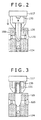
- Fig. 2 is a view explaining a reaction container transfer mechanism and a mechanism related to checking a light source light quantity according to the present invention.
- a light source 124 is installed at the bottom of a reaction container installation section 120 and a detector 125 to detect the light scattered from a reaction container in the light projected from the light source 124 is installed.
- the detector 125 is installed on a side and in a recess of the reaction container installation section 120 as shown in the figure.
- Fig. 2 shows the case of installing two detectors.
- a reaction container transfer mechanism 117 holds a reaction container 106, inserts the reaction container 106 into a recess of the reaction container installation section 120 while descending, and places the reaction container 106.
- a detector 130 for checking a light source light quantity to detect the light projected from the light source 124 is installed in the reaction container transfer mechanism 117.
- the detector 130 is installed at the root of two hold arms to hold the reaction container 106 of the reaction container transfer mechanism 117 so as to be able to detect light in Fig. 2 but the detector 130 may not necessarily be installed at the position as long as the detector 130 can detect the light projected from the light source 124.
- the reaction container transfer mechanism 117 moves over the top face of the reaction container installation section 120 of the detection section 119 while either holding or not holding the reaction container and detects the light from the light source 124 with the detector 130 for checking a light source light quantity.
- the computer (control section) 123 raises an alarm stating that the light source is insufficient through the interface 127. Otherwise, the computer (control section) 123, through the interface 127, raises warning such as an alarm showing the abnormality of a light quantity and facilitates the exchange of the light source or raises an alarm facilitating the confirmation of the light source. In this way, an operator can recognize light source abnormality, light quantity abnormality, etc.
- the detector 130 for checking a light source light quantity can be used for positioning the reaction container transfer mechanism 117 in the horizontal direction in addition to the purpose of checking a light source light quantity.
- the computer (control section) 123 controls the reaction container transfer mechanism 117 so as to stop moving in the horizontal direction on the basis of the light quantity detected with the detector 130 and thereby the light quantity from the light source can be detected at a nearly identical position every time. For example, by controlling the reaction container transfer mechanism 117 so as to stop at a threshold value lower than the threshold value for light quantity check, the reaction container transfer mechanism 117 can stop at a nearly identical position regardless of a deteriorated state even when the output of the light source deteriorates.
- the computer (control section) 123 can recognize that the reaction container transfer mechanism 117 has reached immediately above the reaction container installation section 120 and it is possible to insert the reaction container into the recess accurately, hold the reaction container, and check the light quantity at a nearly identical position.
- Fig. 3 is the case of using an auxiliary tool 131 when the light quantity of the light source 124 is checked.
- an auxiliary tool 131 for light quantity check comprising a material that does not transmit light is held by the reaction container transfer mechanism 117 and installed at the reaction container installation section 120 and light is received through the auxiliary tool 131. That is, the auxiliary tool 131 is only required to: be able to detect light projected from the light source 124; and comprise a material and have a shape allowing light from exterior to be shielded.
- the auxiliary tool 131 may comprise black resin having a cylindrical shape.
- the auxiliary tool 131 shown in the figure is only an example and the shape may not be cylindrical as long as the shape can effectively take in light source light.
- the auxiliary tool makes it possible to prevent noises caused by external light from being detected and check a light quantity accurately.
- the auxiliary tool 131 may also be configured so as to be always prepared in the reaction container supply section 115 and transferred from the reaction container supply section 115 to the reaction container installation section 120 by the reaction container transfer mechanism 117 in response to the request of light quantity check.
- a method for confirmation when a flaw or dirt exists in a reaction container is explained hereunder (refer to Fig. 1 ).
- the light quantity of the light source 124 is confirmed by the detector 130 for checking a light source light quantity or the like and that the light source has no abnormality is confirmed beforehand.
- the detector 130 for checking a light source light quantity detects the light source light having been transmitted through an empty reaction container and, if the light quantity is smaller than a predetermined threshold value, an alarm stating that the empty reaction container has an abnormality is raised or an alarm of indicating the exchange of the reaction container or the like is raised.
- the present invention has heretofore been explained.
- the present invention makes it possible to provide a less expensive automatic analysis apparatus that can avoid the complexity of the apparatus configuration by using a detector 130 for checking a light source light quantity used commonly for a plurality of detection sections 119. Further, the present invention makes it possible to reduce variation between detectors. Furthermore, by installing a light source at the bottom of a reaction container installation section, it is possible to measure whole agglutination reaction, suppress the unevenness of blood agglutination reaction measurement caused by the unevenness of agglutination reaction such as blood coagulation, and obtain a highly accurate measurement result.
Landscapes
- Health & Medical Sciences (AREA)
- Life Sciences & Earth Sciences (AREA)
- Chemical & Material Sciences (AREA)
- Immunology (AREA)
- Physics & Mathematics (AREA)
- Analytical Chemistry (AREA)
- Biochemistry (AREA)
- General Health & Medical Sciences (AREA)
- General Physics & Mathematics (AREA)
- Pathology (AREA)
- Engineering & Computer Science (AREA)
- Hematology (AREA)
- Biomedical Technology (AREA)
- Molecular Biology (AREA)
- Urology & Nephrology (AREA)
- Chemical Kinetics & Catalysis (AREA)
- Medicinal Chemistry (AREA)
- Microbiology (AREA)
- Food Science & Technology (AREA)
- Biotechnology (AREA)
- Robotics (AREA)
- Cell Biology (AREA)
- Plasma & Fusion (AREA)
- Automatic Analysis And Handling Materials Therefor (AREA)
- Investigating Or Analysing Materials By The Use Of Chemical Reactions (AREA)
- Investigating Or Analysing Materials By Optical Means (AREA)
- Investigating Or Analysing Biological Materials (AREA)
Abstract
Description
- The present invention relates: to an automatic analysis apparatus to automatically analyze a biological sample component such as blood; and in particular to a method for confirming an output light quantity of a scattered light light source used for blood coagulation measurement and the like.
- In an automatic analysis apparatus that measures on the basis of scattered light quantity change caused by blood coagulation and the like, a reaction liquid is irradiated with light and measured. In a light source however, it sometimes happens that a light quantity reduces by usage conditions, aging, dirt, and so on. Consequently, various methods for confirming a light quantity are adopted in conformity with apparatuses. Further, in blood coagulation measurement of a type based on scattered light measurement, a configuration of arranging a detector at an angle of about 90° to a light source and receiving scattered light is generally adopted and an apparatus having measurement sections at multiple places for increasing processing ability is the main stream. Furthermore, reaction containers are non-reusable in many blood coagulation items and a reaction container transfer mechanism to place and discard reaction containers is installed.
- Meanwhile, in recent years an automatic analysis apparatus is required to be an apparatus capable of downsizing, low cost, high reliability, and high processing ability. With regard to the confirmation of the variation of a light source light quantity too, downsizing, low cost, high reliability, and others are required likewise.
- In Patent Literature 1, a configuration of arranging a light source under a reaction container and two detectors laterally is disclosed. Further, a technology of installing a detector to compensate a light quantity variation portion laterally to a light source is disclosed.
- Further, in Patent Literature 2, a technology of placing a light source beside a reaction container and installing a photodetector in a direction perpendicular to the incident direction of measurement light is disclosed.
-
- Patent Literature 1: Japanese Published Unexamined Application No.
S59-28642 - Patent Literature 2: Japanese Published Unexamined Application No.
2001-165937 - In the technology of Patent Literature 1, a detector for checking a light quantity has to be installed for each light source and, when a plurality of light sources are present, the problem is that detectors for checking light quantities of a number equal to the light sources are necessary, the apparatus configuration gets complex, and the apparatus becomes costly. Further, the technology of Patent Literature 2 is a method of projecting light from a side of a reaction container, whole agglutination reaction cannot be measured in the case of this method, and hence blood agglutination reaction measurement comes to be uneven due to the unevenness of agglutination reaction such as blood coagulation.
- The representative features of the present invention are as follows.
-
- (1) The present invention is an automatic analysis apparatus provided with: a plurality of detection sections, each of which has a reaction container installation section in which a reaction container in which a sample and a reagent react is placed; a light source being installed at the bottom of the reaction container installation section and projecting light; a first detector being installed in the reaction container installation section and detecting the light scattered from the reaction container in the light projected from the light source; a reaction container transfer mechanism being used commonly for the detection sections and holding, transferring, and placing the reaction containers; and a second detector being installed in the reaction container transfer mechanism and detecting the light projected from the light sources.
- (2) In an automatic analysis apparatus according to the item (1), the automatic analysis apparatus is provided with a control section to raise an alarm stating that the light quantity of the light source is insufficient or facilitating the exchange of the light source when the light quantity detected with the second detector is smaller than a predetermined threshold value.
- (3) In an automatic analysis apparatus according to the item (1) or (2) : the automatic analysis apparatus is provided with an auxiliary tool of a material and a shape making it possible to detect the light projected from the light source and shield light from exterior; and the auxiliary tool is held by the reaction container transfer mechanism, is transferred above the light source, and detects the light projected from the light source with the second detector in the state of shielding the light from the exterior.
- (4) In an automatic analysis apparatus according to any one of items (1) to (3) : an empty reaction container is placed in the reaction container installation section; and an alarm stating that the empty reaction container has an abnormality is raised when the light quantity detected with the second detector in the light having been transmitted through the empty reaction container is smaller than a predetermined second threshold value.
- (5) In an automatic analysis apparatus according to any one of the items (1) to (4), the drive of the reaction container transfer mechanism in the horizontal direction stops on the basis of the light quantity detected with the second detector.
- The present invention makes it possible to: eliminate the need for detectors for checking light quantities of a number equal to light sources; avoid the complexity of an apparatus configuration; and provide an inexpensive automatic analysis apparatus. Further, by commonly using a detector for checking a light quantity, it is possible to reduce variation between detectors. Furthermore, by installing a light source at the bottom of a reaction container installation section, it is possible to measure whole agglutination reaction, suppress the unevenness of blood agglutination reaction measurement caused by the unevenness of agglutination reaction such as blood coagulation, and obtain a highly accurate measurement result.
-
-
Fig. 1 is a schematic view of a general blood coagulation automatic analysis apparatus. -
Fig. 2 is a representative example of the present invention. -
Fig. 3 is an example of using an auxiliary tool for detecting the variation of a light source light quantity. -
Fig. 1 is an example of a general blood coagulation apparatus configuration. The function of each section is publicly known and hence detailed descriptions are omitted. Asampling mechanism 101 is configured so that: asampling arm 102 moves vertically and rotatably; and asample dispensing probe 103 attached to thesampling arm 102 sucks a sample in asample container 105 placed in asample disk 104 rotating horizontally and discharges the sample to areaction container 106. Thesample dispensing probe 103 carries out the operations of sucking and discharging a sample in response to the operation of asample syringe pump 107. Likewise, areagent dispensing mechanism 108 is configured so that: areagent dispensing arm 109 moves vertically and rotatably; areagent dispensing probe 110 sucks a sample in areagent container 112 placed in areagent disk 111 and discharges the sample to areaction container 106; and areagent heating mechanism 113 is incorporated in the interior. A sample and a reagent discharged to areaction container 106 react. Thereagent dispensing probe 110 carries out the operations of sucking and discharging a reagent in response to the operation of areagent syringe pump 114. Areaction container 106 is retained by a reactioncontainer retaining section 118 of a rotating reactioncontainer transfer mechanism 117, moves rotatably from a reactioncontainer supply section 115, and is placed in a reactioncontainer installation section 120 of adetection section 119. The reactioncontainer installation section 120 has a recess so as to be able to place areaction container 106 and thereaction container 106 can be inserted into the recess. Here, two or more reactioncontainer installation sections 120 are installed although it is not shown in the figure and the present apparatus has a plurality ofdetection sections 119. The reactioncontainer transfer mechanism 117 is a mechanism used commonly for the detection sections and holds, transfers, and places areaction container 106. - The flow of measurement is explained hereunder. Firstly, analysis items to be analyzed for each sample are inputted from an input device such as a
keyboard 121 or the screen of aCRT 122. The operation of the unit is controlled by a computer (control section) 123. By thesampling mechanism 101, a sample in asample container 105 placed in thesample disk 104 is sucked and dispensed to areaction container 106 placed in the reactioncontainer installation section 120 in thedetection section 119. Successively likewise, by thereagent dispensing mechanism 108, a reagent is sucked from areagent container 112 placed in thereagent disk 111, heated to an appropriate temperature by thereagent heating mechanism 113, and dispensed to thereaction container 106. Blood coagulation reaction starts promptly by the reagent discharge pressure. Light from thelight source 124 is projected to thereaction container 106, the light scattered by a reaction solution in the reaction container is detected with thedetector 125 such as a photodiode, a photometric signal enters the computer (control section) 123 via aninterface 127 through an A/D converter 126, and coagulation reaction time is computed. The result is, through theinterface 127, outputted by printing with aprinter 128 or outputted on the screen of the CRT 122 and stored in a hard disk as amemory 129. Thereaction container 106 after finishing the photometry is retained by the reactioncontainer transfer mechanism 117 and discarded to a reactioncontainer disposal section 116. -
Fig. 2 is a view explaining a reaction container transfer mechanism and a mechanism related to checking a light source light quantity according to the present invention. Alight source 124 is installed at the bottom of a reactioncontainer installation section 120 and adetector 125 to detect the light scattered from a reaction container in the light projected from thelight source 124 is installed. For example, thedetector 125 is installed on a side and in a recess of the reactioncontainer installation section 120 as shown in the figure. Here,Fig. 2 shows the case of installing two detectors. A reactioncontainer transfer mechanism 117 holds areaction container 106, inserts thereaction container 106 into a recess of the reactioncontainer installation section 120 while descending, and places thereaction container 106. Adetector 130 for checking a light source light quantity to detect the light projected from thelight source 124 is installed in the reactioncontainer transfer mechanism 117. Thedetector 130 is installed at the root of two hold arms to hold thereaction container 106 of the reactioncontainer transfer mechanism 117 so as to be able to detect light inFig. 2 but thedetector 130 may not necessarily be installed at the position as long as thedetector 130 can detect the light projected from thelight source 124. - When a light source light quantity is checked, the reaction
container transfer mechanism 117, in the same manner as the operation at the time of reaction container supply, moves over the top face of the reactioncontainer installation section 120 of thedetection section 119 while either holding or not holding the reaction container and detects the light from thelight source 124 with thedetector 130 for checking a light source light quantity. On this occasion, when the light quantity detected by thedetector 130 is smaller than a predetermined threshold value, the computer (control section) 123 raises an alarm stating that the light source is insufficient through theinterface 127. Otherwise, the computer (control section) 123, through theinterface 127, raises warning such as an alarm showing the abnormality of a light quantity and facilitates the exchange of the light source or raises an alarm facilitating the confirmation of the light source. In this way, an operator can recognize light source abnormality, light quantity abnormality, etc. - Meanwhile, the
detector 130 for checking a light source light quantity can be used for positioning the reactioncontainer transfer mechanism 117 in the horizontal direction in addition to the purpose of checking a light source light quantity. The computer (control section) 123 controls the reactioncontainer transfer mechanism 117 so as to stop moving in the horizontal direction on the basis of the light quantity detected with thedetector 130 and thereby the light quantity from the light source can be detected at a nearly identical position every time. For example, by controlling the reactioncontainer transfer mechanism 117 so as to stop at a threshold value lower than the threshold value for light quantity check, the reactioncontainer transfer mechanism 117 can stop at a nearly identical position regardless of a deteriorated state even when the output of the light source deteriorates. As a result, the computer (control section) 123 can recognize that the reactioncontainer transfer mechanism 117 has reached immediately above the reactioncontainer installation section 120 and it is possible to insert the reaction container into the recess accurately, hold the reaction container, and check the light quantity at a nearly identical position. -
Fig. 3 is the case of using anauxiliary tool 131 when the light quantity of thelight source 124 is checked. When a light quantity is checked, anauxiliary tool 131 for light quantity check comprising a material that does not transmit light is held by the reactioncontainer transfer mechanism 117 and installed at the reactioncontainer installation section 120 and light is received through theauxiliary tool 131. That is, theauxiliary tool 131 is only required to: be able to detect light projected from thelight source 124; and comprise a material and have a shape allowing light from exterior to be shielded. For example, theauxiliary tool 131 may comprise black resin having a cylindrical shape. Theauxiliary tool 131 shown in the figure is only an example and the shape may not be cylindrical as long as the shape can effectively take in light source light. The auxiliary tool makes it possible to prevent noises caused by external light from being detected and check a light quantity accurately. Theauxiliary tool 131 may also be configured so as to be always prepared in the reactioncontainer supply section 115 and transferred from the reactioncontainer supply section 115 to the reactioncontainer installation section 120 by the reactioncontainer transfer mechanism 117 in response to the request of light quantity check. - An example of a method for confirmation when a flaw or dirt exists in a reaction container is explained hereunder (refer to
Fig. 1 ). The light quantity of thelight source 124 is confirmed by thedetector 130 for checking a light source light quantity or the like and that the light source has no abnormality is confirmed beforehand. When a reaction container is placed, thedetector 130 for checking a light source light quantity detects the light source light having been transmitted through an empty reaction container and, if the light quantity is smaller than a predetermined threshold value, an alarm stating that the empty reaction container has an abnormality is raised or an alarm of indicating the exchange of the reaction container or the like is raised. In this way, by confirming that the light source does not have an abnormality beforehand, then placing an empty reaction container in the reactioncontainer installation section 120, and detecting the light having been transmitted through the reaction container with thedetector 130, it is possible to detect abnormality such as a flaw or dirt of the reaction container. - The present invention has heretofore been explained. The present invention makes it possible to provide a less expensive automatic analysis apparatus that can avoid the complexity of the apparatus configuration by using a
detector 130 for checking a light source light quantity used commonly for a plurality ofdetection sections 119. Further, the present invention makes it possible to reduce variation between detectors. Furthermore, by installing a light source at the bottom of a reaction container installation section, it is possible to measure whole agglutination reaction, suppress the unevenness of blood agglutination reaction measurement caused by the unevenness of agglutination reaction such as blood coagulation, and obtain a highly accurate measurement result. -
- 101
- Sampling mechanism
- 102
- Sampling arm
- 103
- Sample dispensing probe
- 104
- Sample disk
- 105
- Sample container
- 106
- Reaction container
- 107
- Sample syringe pump
- 108
- Reagent dispensing mechanism
- 109
- Reagent dispensing arm
- 110
- Reagent dispensing probe
- 111
- Reagent disk
- 112
- Reagent container
- 113
- Reagent heating mechanism
- 114
- Reagent syringe pump
- 115
- Reaction container supply section
- 116
- Reaction container disposal section
- 117
- Reaction container transfer mechanism
- 118
- Reaction container retaining section
- 119
- Detection section
- 120
- Reaction container installation section
- 121
- Keyboard
- 122
- CRT
- 123
- Computer (control section)
- 124
- Light source
- 125
- Detector
- 126
- A/D converter
- 127
- Interface
- 128
- Printer
- 129
- Memory
- 130
- Detector for checking a light source light quantity
- 131
- Auxiliary tool
Claims (5)
- An automatic analysis apparatus comprising:a plurality of detection sections, each of which has a reaction container installation section in which a reaction container in which a sample and a reagent react is placed;a light source installed at the bottom of the reaction container installation section and projecting light;a first detector installed in the reaction container installation section and detecting the light scattered from the reaction container in the light projected from the light source;a reaction container transfer mechanism used commonly for the detection sections and holding, transferring, and placing the reaction containers; anda second detector installed in the reaction container transfer mechanism and detecting the light projected from the light sources.
- The automatic analysis apparatus according to Claim 1, comprising a control section to raise an alarm stating that the light quantity of the light source is insufficient or facilitating the exchange of the light source when the light quantity detected with the second detector is smaller than a predetermined threshold value.
- The automatic analysis apparatus according to Claim 1 or 2, comprising an auxiliary tool of a material and a shape making it possible to detect the light projected from the light source and shield light from exterior,
wherein the auxiliary tool is held by the reaction container transfer mechanism, is transferred above the light source, and detects the light projected from the light source with the second detector in the state of shielding the light from the exterior. - The automatic analysis apparatus according to any one of Claims 1 to 3,
wherein an empty reaction container is placed in the reaction container installation section; and
an alarm stating that the empty reaction container has an abnormality is raised when the light quantity detected with the second detector in the light having been transmitted through the empty reaction container is smaller than a predetermined second threshold value. - The automatic analysis apparatus according to any one of Claims 1 to 4,
wherein the drive of the reaction container transfer mechanism in the horizontal direction stops on the basis of the light quantity detected with the second detector.
Applications Claiming Priority (2)
| Application Number | Priority Date | Filing Date | Title |
|---|---|---|---|
| JP2012126668A JP5953129B2 (en) | 2012-06-04 | 2012-06-04 | Automatic analyzer |
| PCT/JP2013/064427 WO2013183459A1 (en) | 2012-06-04 | 2013-05-24 | Automatic analysis device |
Publications (3)
| Publication Number | Publication Date |
|---|---|
| EP2857845A1 true EP2857845A1 (en) | 2015-04-08 |
| EP2857845A4 EP2857845A4 (en) | 2016-02-10 |
| EP2857845B1 EP2857845B1 (en) | 2019-08-14 |
Family
ID=49711856
Family Applications (1)
| Application Number | Title | Priority Date | Filing Date |
|---|---|---|---|
| EP13800133.4A Active EP2857845B1 (en) | 2012-06-04 | 2013-05-24 | Automatic analysis device |
Country Status (5)
| Country | Link |
|---|---|
| US (1) | US9506940B2 (en) |
| EP (1) | EP2857845B1 (en) |
| JP (1) | JP5953129B2 (en) |
| CN (1) | CN104335051B (en) |
| WO (1) | WO2013183459A1 (en) |
Cited By (1)
| Publication number | Priority date | Publication date | Assignee | Title |
|---|---|---|---|---|
| JPWO2016006362A1 (en) * | 2014-07-07 | 2017-04-27 | 株式会社日立ハイテクノロジーズ | Automatic analyzer |
Families Citing this family (10)
| Publication number | Priority date | Publication date | Assignee | Title |
|---|---|---|---|---|
| CN111175240A (en) * | 2014-05-30 | 2020-05-19 | 株式会社日立高新技术 | Automatic analyzer |
| EP3176585B1 (en) * | 2014-07-29 | 2019-10-02 | Hitachi High-Technologies Corporation | Automatic analysis apparatus |
| WO2016136377A1 (en) * | 2015-02-25 | 2016-09-01 | 株式会社 日立ハイテクノロジーズ | Automated analysis device |
| WO2017047240A1 (en) * | 2015-09-17 | 2017-03-23 | 株式会社 日立ハイテクノロジーズ | Automated analysis device |
| JP6766155B2 (en) | 2016-09-14 | 2020-10-07 | 株式会社日立ハイテク | Automatic analyzer |
| JP1574656S (en) | 2016-09-29 | 2018-10-09 | ||
| JP1574655S (en) | 2016-09-29 | 2018-10-09 | ||
| CN111201440B (en) * | 2017-10-10 | 2021-04-20 | 株式会社日立高新技术 | Automatic analyzer |
| JP7520672B2 (en) | 2020-09-30 | 2024-07-23 | キヤノンメディカルシステムズ株式会社 | Automatic analyzer, tool, and method for calibrating automatic analyzer |
| JP7828764B2 (en) * | 2022-01-18 | 2026-03-12 | キヤノンメディカルシステムズ株式会社 | automatic analyzer |
Family Cites Families (17)
| Publication number | Priority date | Publication date | Assignee | Title |
|---|---|---|---|---|
| US4363245A (en) * | 1980-11-18 | 1982-12-14 | Peerless Electronics Research Corp. | Sampling apparatus |
| JPS5928642A (en) | 1982-08-11 | 1984-02-15 | Hitachi Ltd | scattering photometer |
| JPS61145433A (en) * | 1984-12-19 | 1986-07-03 | Hitachi Ltd | Sample introduction device |
| JPH0754326B2 (en) * | 1986-06-24 | 1995-06-07 | 株式会社東芝 | Automatic chemical analyzer |
| JPH0644003B2 (en) * | 1987-02-04 | 1994-06-08 | 日立化成工業株式会社 | Analysis equipment |
| JP2819736B2 (en) * | 1990-02-22 | 1998-11-05 | 株式会社島津製作所 | Automatic sample injector for multiple samples |
| DE4123817C2 (en) * | 1991-07-18 | 1994-06-09 | Berthold Lab Prof Dr | Radiation measuring device, in particular for measuring luminescence |
| JP3533502B2 (en) * | 1994-10-14 | 2004-05-31 | 株式会社日立製作所 | Automatic chemical analyzer |
| EP0909389A2 (en) * | 1996-07-05 | 1999-04-21 | Beckman Coulter, Inc. | Automated sample processing system |
| JP2001149930A (en) * | 1999-11-26 | 2001-06-05 | Dkk Toa Corp | UV oxidation equipment |
| JP3446696B2 (en) * | 1999-12-10 | 2003-09-16 | 株式会社島津製作所 | Automatic biochemical analyzer |
| JP4446592B2 (en) * | 2000-12-25 | 2010-04-07 | シスメックス株式会社 | Liquid sample measurement unit and automatic liquid sample analyzer equipped with the same |
| JP4829716B2 (en) * | 2006-08-18 | 2011-12-07 | シスメックス株式会社 | Blood coagulation analyzer |
| JP2008209338A (en) * | 2007-02-28 | 2008-09-11 | Hitachi High-Technologies Corp | Automatic analyzer |
| JP5325205B2 (en) * | 2008-03-18 | 2013-10-23 | アークレイ株式会社 | Portable analyzer |
| KR101157177B1 (en) * | 2008-11-27 | 2012-06-20 | 삼성전자주식회사 | System and method for processing target material |
| JP5236612B2 (en) * | 2009-11-04 | 2013-07-17 | 株式会社日立ハイテクノロジーズ | Automatic analyzer |
-
2012
- 2012-06-04 JP JP2012126668A patent/JP5953129B2/en active Active
-
2013
- 2013-05-24 WO PCT/JP2013/064427 patent/WO2013183459A1/en not_active Ceased
- 2013-05-24 US US14/402,416 patent/US9506940B2/en active Active
- 2013-05-24 CN CN201380027466.4A patent/CN104335051B/en active Active
- 2013-05-24 EP EP13800133.4A patent/EP2857845B1/en active Active
Cited By (1)
| Publication number | Priority date | Publication date | Assignee | Title |
|---|---|---|---|---|
| JPWO2016006362A1 (en) * | 2014-07-07 | 2017-04-27 | 株式会社日立ハイテクノロジーズ | Automatic analyzer |
Also Published As
| Publication number | Publication date |
|---|---|
| EP2857845A4 (en) | 2016-02-10 |
| JP5953129B2 (en) | 2016-07-20 |
| WO2013183459A1 (en) | 2013-12-12 |
| EP2857845B1 (en) | 2019-08-14 |
| JP2013250218A (en) | 2013-12-12 |
| CN104335051A (en) | 2015-02-04 |
| US9506940B2 (en) | 2016-11-29 |
| US20150147230A1 (en) | 2015-05-28 |
| CN104335051B (en) | 2016-03-02 |
Similar Documents
| Publication | Publication Date | Title |
|---|---|---|
| US9506940B2 (en) | Automatic analysis apparatus | |
| CN110383075B (en) | automatic analysis device | |
| US8075840B2 (en) | Automatic multi-purpose analyzer | |
| EP3101431B1 (en) | Automatic analytical apparatus | |
| JP5210903B2 (en) | Sample analyzer | |
| US20140220693A1 (en) | Automatic analyzer | |
| US9671419B2 (en) | Liquid collection device and automated analyzer provided therewith | |
| JP6567890B2 (en) | Automatic analyzer | |
| JP2010038659A (en) | Sample analyzing method and sample analyzer | |
| JP5236612B2 (en) | Automatic analyzer | |
| WO2019138720A1 (en) | Automatic analysis device | |
| JP5593291B2 (en) | Automatic analyzer | |
| EP3696549B1 (en) | Automated analyzer | |
| EP3171180B1 (en) | Automatic analysis device | |
| CN104919322B (en) | Automatic analysis device | |
| JP6863708B2 (en) | Automatic analyzer | |
| WO2021079645A1 (en) | Automatic analysis device and method for dispensing reagent | |
| JP6077075B2 (en) | Automatic analyzer | |
| EP4722731A1 (en) | Automatic analysis device | |
| JP5806769B2 (en) | Analysis method, dispensing method and temperature raising method | |
| JP5604551B2 (en) | Automatic analyzer |
Legal Events
| Date | Code | Title | Description |
|---|---|---|---|
| PUAI | Public reference made under article 153(3) epc to a published international application that has entered the european phase |
Free format text: ORIGINAL CODE: 0009012 |
|
| 17P | Request for examination filed |
Effective date: 20141121 |
|
| AK | Designated contracting states |
Kind code of ref document: A1 Designated state(s): AL AT BE BG CH CY CZ DE DK EE ES FI FR GB GR HR HU IE IS IT LI LT LU LV MC MK MT NL NO PL PT RO RS SE SI SK SM TR |
|
| AX | Request for extension of the european patent |
Extension state: BA ME |
|
| DAX | Request for extension of the european patent (deleted) | ||
| RA4 | Supplementary search report drawn up and despatched (corrected) |
Effective date: 20160112 |
|
| RIC1 | Information provided on ipc code assigned before grant |
Ipc: G01N 35/04 20060101ALI20160106BHEP Ipc: G01N 21/82 20060101ALI20160106BHEP Ipc: G01N 35/00 20060101AFI20160106BHEP Ipc: G01N 21/01 20060101ALI20160106BHEP Ipc: G01N 21/49 20060101ALI20160106BHEP |
|
| GRAJ | Information related to disapproval of communication of intention to grant by the applicant or resumption of examination proceedings by the epo deleted |
Free format text: ORIGINAL CODE: EPIDOSDIGR1 |
|
| STAA | Information on the status of an ep patent application or granted ep patent |
Free format text: STATUS: GRANT OF PATENT IS INTENDED |
|
| GRAP | Despatch of communication of intention to grant a patent |
Free format text: ORIGINAL CODE: EPIDOSNIGR1 |
|
| RIC1 | Information provided on ipc code assigned before grant |
Ipc: G01N 21/49 20060101ALI20190410BHEP Ipc: G01N 15/06 20060101ALN20190410BHEP Ipc: G01N 21/25 20060101ALN20190410BHEP Ipc: G01N 35/00 20060101AFI20190410BHEP Ipc: G01N 21/01 20060101ALI20190410BHEP Ipc: G01N 35/04 20060101ALI20190410BHEP Ipc: G01N 21/82 20060101ALI20190410BHEP Ipc: G01N 21/51 20060101ALN20190410BHEP Ipc: G01N 33/86 20060101ALN20190410BHEP Ipc: G01N 21/15 20060101ALN20190410BHEP Ipc: G01N 35/02 20060101ALN20190410BHEP |
|
| INTG | Intention to grant announced |
Effective date: 20190502 |
|
| GRAS | Grant fee paid |
Free format text: ORIGINAL CODE: EPIDOSNIGR3 |
|
| GRAA | (expected) grant |
Free format text: ORIGINAL CODE: 0009210 |
|
| STAA | Information on the status of an ep patent application or granted ep patent |
Free format text: STATUS: THE PATENT HAS BEEN GRANTED |
|
| AK | Designated contracting states |
Kind code of ref document: B1 Designated state(s): AL AT BE BG CH CY CZ DE DK EE ES FI FR GB GR HR HU IE IS IT LI LT LU LV MC MK MT NL NO PL PT RO RS SE SI SK SM TR |
|
| REG | Reference to a national code |
Ref country code: GB Ref legal event code: FG4D |
|
| REG | Reference to a national code |
Ref country code: CH Ref legal event code: EP Ref country code: AT Ref legal event code: REF Ref document number: 1167654 Country of ref document: AT Kind code of ref document: T Effective date: 20190815 |
|
| REG | Reference to a national code |
Ref country code: IE Ref legal event code: FG4D |
|
| REG | Reference to a national code |
Ref country code: DE Ref legal event code: R096 Ref document number: 602013059222 Country of ref document: DE |
|
| REG | Reference to a national code |
Ref country code: NL Ref legal event code: MP Effective date: 20190814 |
|
| REG | Reference to a national code |
Ref country code: LT Ref legal event code: MG4D |
|
| PG25 | Lapsed in a contracting state [announced via postgrant information from national office to epo] |
Ref country code: HR Free format text: LAPSE BECAUSE OF FAILURE TO SUBMIT A TRANSLATION OF THE DESCRIPTION OR TO PAY THE FEE WITHIN THE PRESCRIBED TIME-LIMIT Effective date: 20190814 Ref country code: SE Free format text: LAPSE BECAUSE OF FAILURE TO SUBMIT A TRANSLATION OF THE DESCRIPTION OR TO PAY THE FEE WITHIN THE PRESCRIBED TIME-LIMIT Effective date: 20190814 Ref country code: BG Free format text: LAPSE BECAUSE OF FAILURE TO SUBMIT A TRANSLATION OF THE DESCRIPTION OR TO PAY THE FEE WITHIN THE PRESCRIBED TIME-LIMIT Effective date: 20191114 Ref country code: NL Free format text: LAPSE BECAUSE OF FAILURE TO SUBMIT A TRANSLATION OF THE DESCRIPTION OR TO PAY THE FEE WITHIN THE PRESCRIBED TIME-LIMIT Effective date: 20190814 Ref country code: LT Free format text: LAPSE BECAUSE OF FAILURE TO SUBMIT A TRANSLATION OF THE DESCRIPTION OR TO PAY THE FEE WITHIN THE PRESCRIBED TIME-LIMIT Effective date: 20190814 Ref country code: PT Free format text: LAPSE BECAUSE OF FAILURE TO SUBMIT A TRANSLATION OF THE DESCRIPTION OR TO PAY THE FEE WITHIN THE PRESCRIBED TIME-LIMIT Effective date: 20191216 Ref country code: FI Free format text: LAPSE BECAUSE OF FAILURE TO SUBMIT A TRANSLATION OF THE DESCRIPTION OR TO PAY THE FEE WITHIN THE PRESCRIBED TIME-LIMIT Effective date: 20190814 Ref country code: NO Free format text: LAPSE BECAUSE OF FAILURE TO SUBMIT A TRANSLATION OF THE DESCRIPTION OR TO PAY THE FEE WITHIN THE PRESCRIBED TIME-LIMIT Effective date: 20191114 |
|
| REG | Reference to a national code |
Ref country code: AT Ref legal event code: MK05 Ref document number: 1167654 Country of ref document: AT Kind code of ref document: T Effective date: 20190814 |
|
| PG25 | Lapsed in a contracting state [announced via postgrant information from national office to epo] |
Ref country code: IS Free format text: LAPSE BECAUSE OF FAILURE TO SUBMIT A TRANSLATION OF THE DESCRIPTION OR TO PAY THE FEE WITHIN THE PRESCRIBED TIME-LIMIT Effective date: 20191214 Ref country code: LV Free format text: LAPSE BECAUSE OF FAILURE TO SUBMIT A TRANSLATION OF THE DESCRIPTION OR TO PAY THE FEE WITHIN THE PRESCRIBED TIME-LIMIT Effective date: 20190814 Ref country code: ES Free format text: LAPSE BECAUSE OF FAILURE TO SUBMIT A TRANSLATION OF THE DESCRIPTION OR TO PAY THE FEE WITHIN THE PRESCRIBED TIME-LIMIT Effective date: 20190814 Ref country code: AL Free format text: LAPSE BECAUSE OF FAILURE TO SUBMIT A TRANSLATION OF THE DESCRIPTION OR TO PAY THE FEE WITHIN THE PRESCRIBED TIME-LIMIT Effective date: 20190814 Ref country code: RS Free format text: LAPSE BECAUSE OF FAILURE TO SUBMIT A TRANSLATION OF THE DESCRIPTION OR TO PAY THE FEE WITHIN THE PRESCRIBED TIME-LIMIT Effective date: 20190814 Ref country code: GR Free format text: LAPSE BECAUSE OF FAILURE TO SUBMIT A TRANSLATION OF THE DESCRIPTION OR TO PAY THE FEE WITHIN THE PRESCRIBED TIME-LIMIT Effective date: 20191115 |
|
| PG25 | Lapsed in a contracting state [announced via postgrant information from national office to epo] |
Ref country code: TR Free format text: LAPSE BECAUSE OF FAILURE TO SUBMIT A TRANSLATION OF THE DESCRIPTION OR TO PAY THE FEE WITHIN THE PRESCRIBED TIME-LIMIT Effective date: 20190814 |
|
| PG25 | Lapsed in a contracting state [announced via postgrant information from national office to epo] |
Ref country code: DK Free format text: LAPSE BECAUSE OF FAILURE TO SUBMIT A TRANSLATION OF THE DESCRIPTION OR TO PAY THE FEE WITHIN THE PRESCRIBED TIME-LIMIT Effective date: 20190814 Ref country code: AT Free format text: LAPSE BECAUSE OF FAILURE TO SUBMIT A TRANSLATION OF THE DESCRIPTION OR TO PAY THE FEE WITHIN THE PRESCRIBED TIME-LIMIT Effective date: 20190814 Ref country code: PL Free format text: LAPSE BECAUSE OF FAILURE TO SUBMIT A TRANSLATION OF THE DESCRIPTION OR TO PAY THE FEE WITHIN THE PRESCRIBED TIME-LIMIT Effective date: 20190814 Ref country code: EE Free format text: LAPSE BECAUSE OF FAILURE TO SUBMIT A TRANSLATION OF THE DESCRIPTION OR TO PAY THE FEE WITHIN THE PRESCRIBED TIME-LIMIT Effective date: 20190814 Ref country code: RO Free format text: LAPSE BECAUSE OF FAILURE TO SUBMIT A TRANSLATION OF THE DESCRIPTION OR TO PAY THE FEE WITHIN THE PRESCRIBED TIME-LIMIT Effective date: 20190814 Ref country code: IT Free format text: LAPSE BECAUSE OF FAILURE TO SUBMIT A TRANSLATION OF THE DESCRIPTION OR TO PAY THE FEE WITHIN THE PRESCRIBED TIME-LIMIT Effective date: 20190814 |
|
| PG25 | Lapsed in a contracting state [announced via postgrant information from national office to epo] |
Ref country code: SM Free format text: LAPSE BECAUSE OF FAILURE TO SUBMIT A TRANSLATION OF THE DESCRIPTION OR TO PAY THE FEE WITHIN THE PRESCRIBED TIME-LIMIT Effective date: 20190814 Ref country code: IS Free format text: LAPSE BECAUSE OF FAILURE TO SUBMIT A TRANSLATION OF THE DESCRIPTION OR TO PAY THE FEE WITHIN THE PRESCRIBED TIME-LIMIT Effective date: 20200224 Ref country code: CZ Free format text: LAPSE BECAUSE OF FAILURE TO SUBMIT A TRANSLATION OF THE DESCRIPTION OR TO PAY THE FEE WITHIN THE PRESCRIBED TIME-LIMIT Effective date: 20190814 Ref country code: SK Free format text: LAPSE BECAUSE OF FAILURE TO SUBMIT A TRANSLATION OF THE DESCRIPTION OR TO PAY THE FEE WITHIN THE PRESCRIBED TIME-LIMIT Effective date: 20190814 |
|
| REG | Reference to a national code |
Ref country code: DE Ref legal event code: R097 Ref document number: 602013059222 Country of ref document: DE |
|
| RAP2 | Party data changed (patent owner data changed or rights of a patent transferred) |
Owner name: HITACHI HIGH-TECH CORPORATION |
|
| PLBE | No opposition filed within time limit |
Free format text: ORIGINAL CODE: 0009261 |
|
| STAA | Information on the status of an ep patent application or granted ep patent |
Free format text: STATUS: NO OPPOSITION FILED WITHIN TIME LIMIT |
|
| REG | Reference to a national code |
Ref country code: DE Ref legal event code: R081 Ref document number: 602013059222 Country of ref document: DE Owner name: HITACHI HIGH-TECH CORPORATION, JP Free format text: FORMER OWNER: HITACHI HIGH-TECHNOLOGIES CORPORATION, TOKYO, JP |
|
| PG2D | Information on lapse in contracting state deleted |
Ref country code: IS |
|
| 26N | No opposition filed |
Effective date: 20200603 |
|
| PG25 | Lapsed in a contracting state [announced via postgrant information from national office to epo] |
Ref country code: SI Free format text: LAPSE BECAUSE OF FAILURE TO SUBMIT A TRANSLATION OF THE DESCRIPTION OR TO PAY THE FEE WITHIN THE PRESCRIBED TIME-LIMIT Effective date: 20190814 |
|
| PG25 | Lapsed in a contracting state [announced via postgrant information from national office to epo] |
Ref country code: MC Free format text: LAPSE BECAUSE OF FAILURE TO SUBMIT A TRANSLATION OF THE DESCRIPTION OR TO PAY THE FEE WITHIN THE PRESCRIBED TIME-LIMIT Effective date: 20190814 Ref country code: LI Free format text: LAPSE BECAUSE OF NON-PAYMENT OF DUE FEES Effective date: 20200531 Ref country code: CH Free format text: LAPSE BECAUSE OF NON-PAYMENT OF DUE FEES Effective date: 20200531 |
|
| REG | Reference to a national code |
Ref country code: BE Ref legal event code: MM Effective date: 20200531 |
|
| GBPC | Gb: european patent ceased through non-payment of renewal fee |
Effective date: 20200524 |
|
| PG25 | Lapsed in a contracting state [announced via postgrant information from national office to epo] |
Ref country code: LU Free format text: LAPSE BECAUSE OF NON-PAYMENT OF DUE FEES Effective date: 20200524 |
|
| PG25 | Lapsed in a contracting state [announced via postgrant information from national office to epo] |
Ref country code: IE Free format text: LAPSE BECAUSE OF NON-PAYMENT OF DUE FEES Effective date: 20200524 Ref country code: GB Free format text: LAPSE BECAUSE OF NON-PAYMENT OF DUE FEES Effective date: 20200524 |
|
| PG25 | Lapsed in a contracting state [announced via postgrant information from national office to epo] |
Ref country code: BE Free format text: LAPSE BECAUSE OF NON-PAYMENT OF DUE FEES Effective date: 20200531 |
|
| PG25 | Lapsed in a contracting state [announced via postgrant information from national office to epo] |
Ref country code: MT Free format text: LAPSE BECAUSE OF FAILURE TO SUBMIT A TRANSLATION OF THE DESCRIPTION OR TO PAY THE FEE WITHIN THE PRESCRIBED TIME-LIMIT Effective date: 20190814 Ref country code: CY Free format text: LAPSE BECAUSE OF FAILURE TO SUBMIT A TRANSLATION OF THE DESCRIPTION OR TO PAY THE FEE WITHIN THE PRESCRIBED TIME-LIMIT Effective date: 20190814 |
|
| PG25 | Lapsed in a contracting state [announced via postgrant information from national office to epo] |
Ref country code: MK Free format text: LAPSE BECAUSE OF FAILURE TO SUBMIT A TRANSLATION OF THE DESCRIPTION OR TO PAY THE FEE WITHIN THE PRESCRIBED TIME-LIMIT Effective date: 20190814 |
|
| REG | Reference to a national code |
Ref country code: FR Ref legal event code: PLFP Year of fee payment: 11 |
|
| PGFP | Annual fee paid to national office [announced via postgrant information from national office to epo] |
Ref country code: DE Payment date: 20250402 Year of fee payment: 13 |
|
| PGFP | Annual fee paid to national office [announced via postgrant information from national office to epo] |
Ref country code: FR Payment date: 20250401 Year of fee payment: 13 |