EP2857836A1 - Gas sensing system and method - Google Patents
Gas sensing system and method Download PDFInfo
- Publication number
- EP2857836A1 EP2857836A1 EP20140181818 EP14181818A EP2857836A1 EP 2857836 A1 EP2857836 A1 EP 2857836A1 EP 20140181818 EP20140181818 EP 20140181818 EP 14181818 A EP14181818 A EP 14181818A EP 2857836 A1 EP2857836 A1 EP 2857836A1
- Authority
- EP
- European Patent Office
- Prior art keywords
- input ports
- gas
- chamber
- blocked
- sensor
- Prior art date
- Legal status (The legal status is an assumption and is not a legal conclusion. Google has not performed a legal analysis and makes no representation as to the accuracy of the status listed.)
- Granted
Links
Images
Classifications
-
- G—PHYSICS
- G01—MEASURING; TESTING
- G01N—INVESTIGATING OR ANALYSING MATERIALS BY DETERMINING THEIR CHEMICAL OR PHYSICAL PROPERTIES
- G01N1/00—Sampling; Preparing specimens for investigation
- G01N1/02—Devices for withdrawing samples
- G01N1/22—Devices for withdrawing samples in the gaseous state
- G01N1/2247—Sampling from a flowing stream of gas
-
- G—PHYSICS
- G01—MEASURING; TESTING
- G01N—INVESTIGATING OR ANALYSING MATERIALS BY DETERMINING THEIR CHEMICAL OR PHYSICAL PROPERTIES
- G01N1/00—Sampling; Preparing specimens for investigation
- G01N1/02—Devices for withdrawing samples
- G01N1/22—Devices for withdrawing samples in the gaseous state
- G01N1/26—Devices for withdrawing samples in the gaseous state with provision for intake from several spaces
-
- G—PHYSICS
- G01—MEASURING; TESTING
- G01N—INVESTIGATING OR ANALYSING MATERIALS BY DETERMINING THEIR CHEMICAL OR PHYSICAL PROPERTIES
- G01N1/00—Sampling; Preparing specimens for investigation
- G01N1/02—Devices for withdrawing samples
- G01N1/22—Devices for withdrawing samples in the gaseous state
- G01N1/2273—Atmospheric sampling
-
- G—PHYSICS
- G01—MEASURING; TESTING
- G01N—INVESTIGATING OR ANALYSING MATERIALS BY DETERMINING THEIR CHEMICAL OR PHYSICAL PROPERTIES
- G01N1/00—Sampling; Preparing specimens for investigation
- G01N2001/002—Devices for supplying or distributing samples to an analysing apparatus
-
- G—PHYSICS
- G01—MEASURING; TESTING
- G01N—INVESTIGATING OR ANALYSING MATERIALS BY DETERMINING THEIR CHEMICAL OR PHYSICAL PROPERTIES
- G01N33/00—Investigating or analysing materials by specific methods not covered by groups G01N1/00 - G01N31/00
- G01N33/0004—Gaseous mixtures, e.g. polluted air
- G01N33/0009—General constructional details of gas analysers, e.g. portable test equipment
- G01N33/0022—General constructional details of gas analysers, e.g. portable test equipment using a number of analysing channels
-
- G—PHYSICS
- G06—COMPUTING OR CALCULATING; COUNTING
- G06Q—INFORMATION AND COMMUNICATION TECHNOLOGY [ICT] SPECIALLY ADAPTED FOR ADMINISTRATIVE, COMMERCIAL, FINANCIAL, MANAGERIAL OR SUPERVISORY PURPOSES; SYSTEMS OR METHODS SPECIALLY ADAPTED FOR ADMINISTRATIVE, COMMERCIAL, FINANCIAL, MANAGERIAL OR SUPERVISORY PURPOSES, NOT OTHERWISE PROVIDED FOR
- G06Q50/00—Information and communication technology [ICT] specially adapted for implementation of business processes of specific business sectors, e.g. utilities or tourism
- G06Q50/40—Business processes related to the transportation industry
Definitions
- the subject matter described herein relates to gas sensor systems for monitoring of gases.
- some aircraft include an air separation unit (ASU) which has a plurality of air separation modules (ASMs).
- ASMs supply an inert gas such as nitrogen to a fuel tank to maintain inerting in the tank as fuel is consumed by the aircraft.
- the inert gas may also be supplied to systems other than fuel tanks.
- Existing measurement systems route the output of ASMs through a gas sensor to determine the relative amounts of gas in the output flow of the ASMs. For example, the amount of oxygen in the combined output flow may be measured. If the amount of oxygen in the combined output exceeds a predetermined threshold, then it's possible that all the ASMs may be, repaired, or replaced, even though only one of the ASMs require servicing. Accordingly, systems and methods to sense gas from a single gas source in a multi-source system may find utility.
- a system to monitor an output of a gas source comprises a chamber comprising a plurality of input ports to receive inputs from a plurality of gas sources, and means for repeatedly blocking one of the plurality of input ports for a period of time, detecting which one of the plurality of input ports is blocked, collecting data from a plurality of samples from the enclosure while the one of the plurality of input ports is blocked, and storing the data in a memory in association with an indicator of which one of the plurality of input ports is blocked.
- an aircraft comprises a fuselage and a system to monitor an output of a gas source comprises a chamber comprising a plurality of input ports to receive inputs from a plurality of gas sources, and means for repeatedly blocking one of the plurality of input ports for a period of time, detecting which one of the plurality of input ports is blocked, collecting data from a plurality of samples from the enclosure while the one of the plurality of input ports is blocked, and storing the data in a memory in association with an indicator of which one of the plurality of input ports is blocked.
- a method to monitor an output of a gas source comprises receiving inputs from a plurality of gas sources in a plurality of input ports in a chamber, repeatedly blocking one of the plurality of input ports for a period of time, detecting which one of the plurality of input ports is blocked, collecting data from a plurality of samples from the enclosure while the one of the plurality of input ports is blocked, and storing the data in a memory in association with an indicator of which one of the plurality of input ports is blocked.
- the invention may be described herein in terms of functional and/or logical block components and various processing steps. For the sake of brevity, conventional techniques related to data transmission, signaling, network control, and other functional aspects of the systems (and the individual operating components of the systems) may not be described in detail herein. Furthermore, the connecting lines shown in the various figures contained herein are intended to represent example functional relationships and/or physical couplings between the various elements. It should be noted that many alternative or additional functional relationships or physical connections may be present in a practical embodiment.
- connection means that one component/feature is in direct physically contact with another component/feature.
- coupled means that one component/feature is directly or indirectly joined to (or directly or indirectly communicates with) another component/feature, and not necessarily directly physically connected.
- a chamber is provided with a plurality of input ports, each of which receives a gas input from a gas source in a multi-source system.
- One of the input ports is blocked for a period of time and data is collected from the remaining input sources.
- the data is stored in association with an indicator of which input port was blocked while the data was collected. This process is then repeated in a pseudo-random fashion to collect a robust data set.
- a processing device may be used to analyze the data to determine a gas measurement from the input ports, which correspond to the respective gas sources.
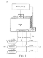
- Fig. 1 is a schematic, high-level illustration of a gas sensing system according to aspects.
- a system to monitor a composition of a gas comprises a chamber 110 which comprises a plurality of input ports 112 configured to receive a potion of gas from a plurality of gas sources 130A, 130B, 130C, which may be referred to collectively herein by reference numeral 130.
- chamber 110 may be determined at least in part by the parameters (e.g., gas flow and pressure) of the gas monitoring system 100.
- Chamber 110 may include one or more vents to allow gas directed into the chamber 110 via input ports 112 to be vented from the chamber 110.
- the specific example system depicted in Fig. 1 includes three gas sources, but it will be understood that other examples may include more or fewer gas sources 130.
- the gas sources 130 may be coupled to a remote system or device via output lines 132A, 132B, 132C, which may be referred to collectively herein by reference number 132.
- the output lines 132 comprise respective feed lines 134A, 134B, 134C, which may be referred to collectively herein by reference numeral 134, coupled to input ports 112 of chamber 110.
- the system 100 further includes one or more position sensors 140. Additional details of the chamber 110 will be described below with reference to Figs. 2-4 .
- System 100 further comprises at least one gas sensor 150 positioned to monitor the gas in chamber 110.
- the particular type of gas sensor 150 may be a product of the gas or gases that system 100 is monitoring.
- the gas sensor 150 may be an oxygen sensor which may be configured to detect the amount of oxygen in the gas in chamber 110.
- the gas sensor 150 may be any of a number of combustible, flammable and toxic gases and vapors such as Carbon Dioxide, Carbon Monoxide, Ozone, Liquefied Petroleum Gas (Propane, Butane, etc.), Combustibles (fuel vapors, etc.) Alcohol, Hydrogen, Smoke, Hydrogen Sulfide, Chlorine, Chlorine Dioxide, Sulfur Dioxide, Nitrogen Dioxide, Ammonia, Hydrogen Chloride, Hydrogen Fluoride, Nitric Oxide, Hydrogen Cyanide, Ethylene Oxide and the like.
- gases and vapors such as Carbon Dioxide, Carbon Monoxide, Ozone, Liquefied Petroleum Gas (Propane, Butane, etc.), Combustibles (fuel vapors, etc.) Alcohol, Hydrogen, Smoke, Hydrogen Sulfide, Chlorine, Chlorine Dioxide, Sulfur Dioxide, Nitrogen Dioxide, Ammonia, Hydrogen Chloride,
- System 100 further includes a processing device 160 communicatively coupled to the position sensor(s) 140 and the gas sensor(s) 150. Additional details of the processing device 160 are described with reference to Fig. 5 , below.
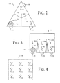
- Figs. 2-4 are schematic top views of chambers 110 which may be used in a gas sensing system, according to aspects.
- the chamber 110 may be configured to block, in a pseudo-random fashion, one of the plurality of input ports 112 for a period of time.
- the chamber 110 presents a triangular cross-sectional shape and comprises three sloped surfaces 114 on the floor of the chamber 110 that intersect at a peak 115.
- the input ports 112 are positioned proximate to the corners, which are the low points, of the respective sloped surfaces 114 of the floor.
- a ball 116 is disposed within chamber 110 and able to roll relatively freely on the sloped surfaces 114 of the chamber 110.
- the ball 116 may comprise a ferrous material, e.g., steel or the like.
- Position sensors 140 may be positioned proximate the input ports 112 to detect when the ball 116 is positioned over the input port 112.
- the position sensors 140 may be embodied as Hall effect sensors.
- the chamber of Fig. 2 may be positioned such that the plane established by the three corners of the floor is approximately level (i.e., parallel to the earth) so that the force of gravity tends to pull the ball 116 into a corner of the chamber 110, such that the ball 116 blocks one of the input ports 112.
- the ball 116 may be moved periodically by subjecting the chamber 110 to acceleration. For example, in a vehicle such as a waterborne vehicle the chamber 110 may be accelerated as a result of motion due to waves or the like. Similarly, in a land-based vehicle chamber 110 may be accelerated as a result of motion due to starting and stopping the vehicle, turning, or hitting bumps on a road.
- an airborne vehicle chamber 110 may be accelerated as a result of motion due to taking off, landing, turning, or turbulence.
- the chamber 110 may be mounted on or coupled to a vibrating element, e.g., a vibrating platform or the like, which may be activated on a periodic basis.
- the ball 116 may roll on the sloped surfaces 114, eventually coming to rest under the force of gravity in one of the corners such that ball 116 blocks an input port 112.
- the combination of the sloped surfaces 114 and the ball 116 provide a mechanism to block, in a pseudo-random fashion, one of the plurality of input ports 112 in the chamber 110.
- the position sensor 140 proximate the input port 112 detects that the ball is blocking the input port and, in response thereto, generates a signal which is communicated to processing device 160.
- the chamber 110 depicted in Fig. 2 has three sloped surfaces 114, in other examples the chamber 110 may be provided with more or fewer sloped surfaces 114.
- the particular number of sloped surfaces is not critical and may be, at least in part, a function of the number of input ports 112 to be monitored.
- a preferred embodiment may include a sloped surface other embodiments may be envisaged such as a flat floor or a floor having sloped surfaces with the input port 112 in a central position with respect to the floor area.
- other embodiments may include multiple balls or devices to block the input ports.
- the example depicted in Fig. 3 uses a technique similar to the example depicted in Fig. 2 to block, in a pseudo-random fashion, one of the plurality of input ports 112 in the chamber 110.
- the chamber 110 comprises a plurality of structures 118 which define a plurality of discrete sections 120A, 120B, 120C, which may be referred to collectively herein by reference numeral 120.
- the input ports 112 are positioned in the respective sections 120, and the floor of the chamber 110 may be sloped such that the input ports 112 are at the low point of the chamber.
- the ball 116 may be moved due to acceleration and will settle, under the force of gravity, back into one of the sections 120, thereby blocking, in a pseudo-random fashion, one of the plurality of input ports 112 for a period of time.
- the position sensor 140 is proximate the input port 112 detects that the ball 116 is blocking the input port and, in response thereto, generates a signal which is communicated to processing device 160.
- the chamber 110 depicted in Fig. 3 has two structures 118 which define three sections 120, in other examples the chamber 110 may be provided with more or fewer structures 118 defining more or fewer sections 120.
- the particular number of sections 120 is not critical and may be, at least in part, a function of the number of input ports 112 to be monitored.
- the chamber 110 may comprise a plurality of input ports 112 which can be selectively opened and closed by a valve or regulator which may be controlled by a remote device such as processing device 160.
- processing device 160 may comprise logic to selectively close one of the input ports 112 in either a pseudo-random or an ordered fashion.
- the input port 112 may remain closed for a predetermined period of time, which may also be determined in a pseudo-random fashion.
- the processing device 160 may utilize a random number generator to select an input port 112 to close and to select a period of time to keep the port closed or use a predetermined time value. After the time period elapses the processing device may utilize the random number generator or a predetermined sequence to close another input port.
- the example depicted in Fig. 4 does not require position detectors 140 because the processing device 160 selects the input port 112 to close.
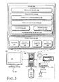
- FIG. 5 is a schematic illustration of a computing system 500 that may be used to monitor for airborne impurities.
- system 500 includes a computing device 508 and one or more accompanying input/output devices including a display 502 having a screen 504, one or more speakers 506, a keyboard 510, one or more other I/O device(s) 512, and a mouse 514.
- the other I/O device(s) 512 may include a touch screen, a voice-activated input device, a track ball, and any other device that allows the system 500 to receive input from a user.
- the computing device 508 includes system hardware 520 and memory 530, which may be implemented as random access memory and/or read-only memory.
- a file store 580 may be communicatively coupled to computing device 508.
- File store 580 may be internal to computing device 508 such as, e.g., one or more hard drives, CD-ROM drives, DVD-ROM drives, or other types of storage devices.
- File store 580 may also be external to computer 508 such as, e.g., one or more external hard drives, network attached storage, or a separate storage network.
- System hardware 520 may include one or more processors 522, video controllers 524, network interfaces 526, and bus structures 528.
- processor 522 may be embodied as an Intel ® Pentium IV® processor available from Intel Corporation, Santa Clara, California, USA.
- processor means any type of computational element, such as but not limited to, a microprocessor, a microcontroller, a complex instruction set computing (CISC) microprocessor, a reduced instruction set (RISC) microprocessor, a very long instruction word (VLIW) microprocessor, or any other type of processor or processing circuit.
- CISC complex instruction set computing
- RISC reduced instruction set
- VLIW very long instruction word
- Graphics controller 524 may function as an adjunction processor that manages graphics and/or video operations. Graphics controller 524 may be integrated onto the motherboard of computing system 500 or may be coupled via an expansion slot on the motherboard.
- network interface 526 could be a wired interface such as an Ethernet interface (see, e.g., Institute of Electrical and Electronics Engineers/IEEE 802.3-2002) or a wireless interface such as an IEEE 802.11a, b or g-compliant interface (see, e.g., IEEE Standard for IT-Telecommunications and information exchange between systems LAN/MAN--Part II: Wireless LAN Medium Access Control (MAC) and Physical Layer (PHY) specifications Amendment 4: Further Higher Data Rate Extension in the 2.4 GHz Band, 802.11G-2003).
- GPRS general packet radio service
- Bus structures 528 connect various components of system hardware 528.
- bus structures 528 may be one or more of several types of bus structure(s) including a memory bus, a peripheral bus or external bus, and/or a local bus using any variety of available bus architectures including, but not limited to, 11-bit bus, Industrial Standard Architecture (ISA), Micro-Channel Architecture (MSA), Extended ISA (EISA), Intelligent Drive Electronics (IDE), VESA Local Bus (VLB), Peripheral Component Interconnect (PCI), Universal Serial Bus (USB), Advanced Graphics Port (AGP), Personal Computer Memory
- ISA Industrial Standard Architecture
- MSA Micro-Channel Architecture
- EISA Extended ISA
- IDE Intelligent Drive Electronics
- VLB VESA Local Bus
- PCI Peripheral Component Interconnect
- USB Universal Serial Bus
- AGP Advanced Graphics Port
- PCMCIA Card International Association bus
- SCSI Small Computer Systems Interface
- Memory 530 may include an operating system 540 for managing operations of computing device 508.
- operating system 540 includes a hardware interface module 554 that provides an interface to system hardware 520.
- operating system 540 may include a file system 550 that manages files used in the operation of computing device 508 and a process control subsystem 552 that manages processes executing on processing device 160.
- Operating system 540 may include (or manage) one or more communication interfaces 544 that may operate in conjunction with system hardware 520 to transceive data packets and/or data streams from a remote source. Operating system 540 may further include a system call interface module 542 that provides an interface between the operating system 540 and one or more application modules resident in memory 530. Operating system 540 may be embodied as a UNIX operating system or any derivative thereof (e.g., Linux, Solaris, etc.) or as a Windows® brand operating system, or other operating systems.
- memory 530 includes a monitoring module 540 to manage gas monitoring operations of the system 100.
- the monitoring module 540 may include logic instructions encoded in a computer-readable storage medium which, when executed by processor 522, cause the processor 522 to manage the system 100 to monitor gas components in chamber 110.
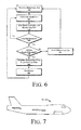
- Fig. 6 is a flowchart illustrating operations in a method detect airborne impurities, according to embodiments.
- operation 610 it is determined which input port 112 in chamber 110 is blocked.
- the position sensors 140 may generate signals which indicate which input port 112 in the chamber 110 is blocked.
- the processing device 160 controls the input ports 112 such that the processing device 160 is aware which input port 112 is closed.
- gas sample data is obtained by a gas sensor 150.
- the gas sensor 150 may sense one or more attributes of a gas in the chamber 110.
- sensor 150 may detect a concentration of oxygen in the chamber 110.
- the processing device 100 may query the gas sensor 150 on a periodic basis, e.g., between about 100_milliseconds and 2000 milliseconds.
- the gas sample data obtained in operation 615 is stored in association with an indicator of the input port 112 which was blocked while the sample data was collected.
- the gas sample data may be stored in a data table or the like in memory 530 of processing device 160.
- operations 615-625 define a loop pursuant to which processing device 160 may collect gas data samples from gas sensor 150.
- the threshold may be set as a predetermined number and may be static or dynamic. Further, the threshold may be a function of the number of input ports 112 in the chamber. In some examples the threshold may vary between about 12 samples and 100 samples.
- the processing device may have to wait for the ball 116 to be moved under the force of acceleration. By contrast, in the example depicted in Fig. 5 the processing device 160 may continue closing input ports 112 in a pseudo-random or ordered fashion until all input ports 112 have been closed.
- the processing device 160 may first determine an average of the gas sample data collected while each input port 112 was blocked. For example, if the processing device 160 is configured to collect 100 data samples for each blocked input port 112 then an average of the 100 data samples is determined.
- the system 100 described herein enables gas sample data to be collected from chamber 110 while the input ports 112 are blocked in a pseudo-random fashion.
- the processing device 160 may then determine a characteristic (i.e. a composition) of the gas associated with any given input port 112.
- This output may be stored in a computer-readable medium such as memory 130 or presented on a user interface, thereby allowing a user to ascertain information about a single gas source 130 in a multi-source system, thereby eliminate the need for multiple expensive sensors and the power and weight requirements needed to support the sensors.
- processing device 160 is described as a fully functioning computer system, it will be recognized that the processing device 160 may be embodied as a specialized controller, e.g., an application specific integrated circuit (ASIC) or a field programmable gate array (FPGA).
- ASIC application specific integrated circuit
- FPGA field programmable gate array
- a system 100 may be incorporated into compartments of on an aircraft 700, such as an airplane, helicopter, spacecraft or the like.
- a system 100 may be incorporated into a ground-based vehicle such as a truck, tank, train, or the like, or on a water-based vehicle such as a ship.
- a system 100 may be incorporated into a land-based device or system.
Landscapes
- Life Sciences & Earth Sciences (AREA)
- Health & Medical Sciences (AREA)
- Chemical & Material Sciences (AREA)
- Engineering & Computer Science (AREA)
- Physics & Mathematics (AREA)
- General Physics & Mathematics (AREA)
- Pathology (AREA)
- Analytical Chemistry (AREA)
- Biochemistry (AREA)
- General Health & Medical Sciences (AREA)
- Immunology (AREA)
- Molecular Biology (AREA)
- Biomedical Technology (AREA)
- Combustion & Propulsion (AREA)
- Food Science & Technology (AREA)
- Medicinal Chemistry (AREA)
- Sampling And Sample Adjustment (AREA)
- Investigating Or Analyzing Materials By The Use Of Fluid Adsorption Or Reactions (AREA)
- Condensed Matter Physics & Semiconductors (AREA)
Abstract
Description
- The subject matter described herein relates to gas sensor systems for monitoring of gases.
- In various applications it may be useful to monitor attributes of one gas source in a plurality of gas sources. For example, some aircraft include an air separation unit (ASU) which has a plurality of air separation modules (ASMs). The ASMs supply an inert gas such as nitrogen to a fuel tank to maintain inerting in the tank as fuel is consumed by the aircraft. The inert gas may also be supplied to systems other than fuel tanks.
- Existing measurement systems route the output of ASMs through a gas sensor to determine the relative amounts of gas in the output flow of the ASMs. For example, the amount of oxygen in the combined output flow may be measured. If the amount of oxygen in the combined output exceeds a predetermined threshold, then it's possible that all the ASMs may be, repaired, or replaced, even though only one of the ASMs require servicing. Accordingly, systems and methods to sense gas from a single gas source in a multi-source system may find utility.
- In one aspect, a system to monitor an output of a gas source comprises a chamber comprising a plurality of input ports to receive inputs from a plurality of gas sources, and means for repeatedly blocking one of the plurality of input ports for a period of time, detecting which one of the plurality of input ports is blocked, collecting data from a plurality of samples from the enclosure while the one of the plurality of input ports is blocked, and storing the data in a memory in association with an indicator of which one of the plurality of input ports is blocked.
- In another aspect, an aircraft comprises a fuselage and a system to monitor an output of a gas source comprises a chamber comprising a plurality of input ports to receive inputs from a plurality of gas sources, and means for repeatedly blocking one of the plurality of input ports for a period of time, detecting which one of the plurality of input ports is blocked, collecting data from a plurality of samples from the enclosure while the one of the plurality of input ports is blocked, and storing the data in a memory in association with an indicator of which one of the plurality of input ports is blocked.
- In another aspect, a method to monitor an output of a gas source, comprises receiving inputs from a plurality of gas sources in a plurality of input ports in a chamber, repeatedly blocking one of the plurality of input ports for a period of time, detecting which one of the plurality of input ports is blocked, collecting data from a plurality of samples from the enclosure while the one of the plurality of input ports is blocked, and storing the data in a memory in association with an indicator of which one of the plurality of input ports is blocked.
- Further areas of applicability will become apparent from the description provided herein. It should be understood that the description and specific examples are intended for purposes of illustration only and are not intended to limit the scope of the present disclosure
- Embodiments of methods and systems in accordance with the teachings of the present disclosure are described in detail below with reference to the following drawings.
-
Fig. 1 is a schematic, high-level illustration of a gas sensing system to detect, according to aspects. -
Figs. 2-4 are schematic top views of chambers which may be used in a gas sensing system, according to aspects. -
Fig. 5 is a schematic illustration of a processing device, according to aspects. -
Fig. 6 is a flowchart illustrating operations in a gas sensing method, according to aspects. -
Fig. 7 is a schematic illustration of an aircraft, according to aspects. - Specific details of certain embodiments are set forth in the following description and the associated figures to provide a thorough understanding of such embodiments. One skilled in the art will understand, however, that alternate embodiments may be practiced without several of the details described in the following description.
- The invention may be described herein in terms of functional and/or logical block components and various processing steps. For the sake of brevity, conventional techniques related to data transmission, signaling, network control, and other functional aspects of the systems (and the individual operating components of the systems) may not be described in detail herein. Furthermore, the connecting lines shown in the various figures contained herein are intended to represent example functional relationships and/or physical couplings between the various elements. It should be noted that many alternative or additional functional relationships or physical connections may be present in a practical embodiment.
- The following description may refer to components or features being "connected" or "coupled" or "bonded" together. As used herein, unless expressly stated otherwise, "connected" means that one component/feature is in direct physically contact with another component/feature. Likewise, unless expressly stated otherwise, "coupled" or "bonded" means that one component/feature is directly or indirectly joined to (or directly or indirectly communicates with) another component/feature, and not necessarily directly physically connected. Thus, although the figures may depict example arrangements of elements, additional intervening elements, devices, features, or components may be present in an actual embodiment.
- Described herein are examples of systems and methods for gas sensing. More particularly, the systems and methods described herein enable the sensing of gas output from a single gas supply source in a multi-source system. In brief, a chamber is provided with a plurality of input ports, each of which receives a gas input from a gas source in a multi-source system. One of the input ports is blocked for a period of time and data is collected from the remaining input sources. The data is stored in association with an indicator of which input port was blocked while the data was collected. This process is then repeated in a pseudo-random fashion to collect a robust data set. A processing device may be used to analyze the data to determine a gas measurement from the input ports, which correspond to the respective gas sources.
-
Fig. 1 is a schematic, high-level illustration of a gas sensing system according to aspects. Referring toFig. 1 , in some aspects a system to monitor a composition of a gas comprises achamber 110 which comprises a plurality ofinput ports 112 configured to receive a potion of gas from a plurality ofgas sources reference numeral 130. - The particular shape and size of
chamber 110 may be determined at least in part by the parameters (e.g., gas flow and pressure) of thegas monitoring system 100.Chamber 110 may include one or more vents to allow gas directed into thechamber 110 viainput ports 112 to be vented from thechamber 110. - The specific example system depicted in
Fig. 1 includes three gas sources, but it will be understood that other examples may include more orfewer gas sources 130. Thegas sources 130 may be coupled to a remote system or device viaoutput lines reference number 132. Theoutput lines 132 compriserespective feed lines reference numeral 134, coupled toinput ports 112 ofchamber 110. In some examples thesystem 100 further includes one ormore position sensors 140. Additional details of thechamber 110 will be described below with reference toFigs. 2-4 . -
System 100 further comprises at least onegas sensor 150 positioned to monitor the gas inchamber 110. The particular type ofgas sensor 150 may be a product of the gas or gases thatsystem 100 is monitoring. For example, in the ASM application described above thegas sensor 150 may be an oxygen sensor which may be configured to detect the amount of oxygen in the gas inchamber 110. In other examples thegas sensor 150 may be any of a number of combustible, flammable and toxic gases and vapors such as Carbon Dioxide, Carbon Monoxide, Ozone, Liquefied Petroleum Gas (Propane, Butane, etc.), Combustibles (fuel vapors, etc.) Alcohol, Hydrogen, Smoke, Hydrogen Sulfide, Chlorine, Chlorine Dioxide, Sulfur Dioxide, Nitrogen Dioxide, Ammonia, Hydrogen Chloride, Hydrogen Fluoride, Nitric Oxide, Hydrogen Cyanide, Ethylene Oxide and the like. -
System 100 further includes aprocessing device 160 communicatively coupled to the position sensor(s) 140 and the gas sensor(s) 150. Additional details of theprocessing device 160 are described with reference toFig. 5 , below. -
Figs. 2-4 are schematic top views ofchambers 110 which may be used in a gas sensing system, according to aspects. In some examples thechamber 110 may be configured to block, in a pseudo-random fashion, one of the plurality ofinput ports 112 for a period of time. In the example depicted inFig. 2 thechamber 110 presents a triangular cross-sectional shape and comprises threesloped surfaces 114 on the floor of thechamber 110 that intersect at apeak 115. Theinput ports 112 are positioned proximate to the corners, which are the low points, of the respectivesloped surfaces 114 of the floor. - A
ball 116 is disposed withinchamber 110 and able to roll relatively freely on thesloped surfaces 114 of thechamber 110. In some embodiments theball 116 may comprise a ferrous material, e.g., steel or the like.Position sensors 140 may be positioned proximate theinput ports 112 to detect when theball 116 is positioned over theinput port 112. In some examples theposition sensors 140 may be embodied as Hall effect sensors. - In operation the chamber of
Fig. 2 may be positioned such that the plane established by the three corners of the floor is approximately level (i.e., parallel to the earth) so that the force of gravity tends to pull theball 116 into a corner of thechamber 110, such that theball 116 blocks one of theinput ports 112. Theball 116 may be moved periodically by subjecting thechamber 110 to acceleration. For example, in a vehicle such as a waterborne vehicle thechamber 110 may be accelerated as a result of motion due to waves or the like. Similarly, in a land-basedvehicle chamber 110 may be accelerated as a result of motion due to starting and stopping the vehicle, turning, or hitting bumps on a road. In anairborne vehicle chamber 110 may be accelerated as a result of motion due to taking off, landing, turning, or turbulence. In an example in which thechamber 110 is used in a stationary environment thechamber 110 may be mounted on or coupled to a vibrating element, e.g., a vibrating platform or the like, which may be activated on a periodic basis. - In response to acceleration of the
chamber 110 theball 116 may roll on thesloped surfaces 114, eventually coming to rest under the force of gravity in one of the corners such thatball 116 blocks aninput port 112. Thus, the combination of the slopedsurfaces 114 and theball 116 provide a mechanism to block, in a pseudo-random fashion, one of the plurality ofinput ports 112 in thechamber 110. Theposition sensor 140 proximate theinput port 112 detects that the ball is blocking the input port and, in response thereto, generates a signal which is communicated toprocessing device 160. - It will be recognized that while the
chamber 110 depicted inFig. 2 has three slopedsurfaces 114, in other examples thechamber 110 may be provided with more or fewer sloped surfaces 114. The particular number of sloped surfaces is not critical and may be, at least in part, a function of the number ofinput ports 112 to be monitored. Further, while a preferred embodiment may include a sloped surface other embodiments may be envisaged such as a flat floor or a floor having sloped surfaces with theinput port 112 in a central position with respect to the floor area. Further, other embodiments may include multiple balls or devices to block the input ports. - The example depicted in
Fig. 3 uses a technique similar to the example depicted inFig. 2 to block, in a pseudo-random fashion, one of the plurality ofinput ports 112 in thechamber 110. Referring toFig. 3 , thechamber 110 comprises a plurality ofstructures 118 which define a plurality ofdiscrete sections input ports 112 are positioned in the respective sections 120, and the floor of thechamber 110 may be sloped such that theinput ports 112 are at the low point of the chamber. - As described above, the
ball 116 may be moved due to acceleration and will settle, under the force of gravity, back into one of the sections 120, thereby blocking, in a pseudo-random fashion, one of the plurality ofinput ports 112 for a period of time. Theposition sensor 140 is proximate theinput port 112 detects that theball 116 is blocking the input port and, in response thereto, generates a signal which is communicated toprocessing device 160. - It will be recognized that while the
chamber 110 depicted inFig. 3 has twostructures 118 which define three sections 120, in other examples thechamber 110 may be provided with more orfewer structures 118 defining more or fewer sections 120. The particular number of sections 120 is not critical and may be, at least in part, a function of the number ofinput ports 112 to be monitored. - In the example depicted in
Fig. 4 thechamber 110 may comprise a plurality ofinput ports 112 which can be selectively opened and closed by a valve or regulator which may be controlled by a remote device such asprocessing device 160. For example,processing device 160 may comprise logic to selectively close one of theinput ports 112 in either a pseudo-random or an ordered fashion. Theinput port 112 may remain closed for a predetermined period of time, which may also be determined in a pseudo-random fashion. For example, theprocessing device 160 may utilize a random number generator to select aninput port 112 to close and to select a period of time to keep the port closed or use a predetermined time value. After the time period elapses the processing device may utilize the random number generator or a predetermined sequence to close another input port. The example depicted inFig. 4 does not requireposition detectors 140 because theprocessing device 160 selects theinput port 112 to close. - As described above, position sensor(s) 140 and the gas sensor(s) 150 may be coupled to a
processing device 160. In some embodiments theprocessing device 160 may be implemented as a general purpose computing system.Fig. 5 is a schematic illustration of acomputing system 500 that may be used to monitor for airborne impurities. some embodiments,system 500 includes acomputing device 508 and one or more accompanying input/output devices including adisplay 502 having ascreen 504, one ormore speakers 506, akeyboard 510, one or more other I/O device(s) 512, and amouse 514. The other I/O device(s) 512 may include a touch screen, a voice-activated input device, a track ball, and any other device that allows thesystem 500 to receive input from a user. - The
computing device 508 includessystem hardware 520 andmemory 530, which may be implemented as random access memory and/or read-only memory. Afile store 580 may be communicatively coupled tocomputing device 508.File store 580 may be internal tocomputing device 508 such as, e.g., one or more hard drives, CD-ROM drives, DVD-ROM drives, or other types of storage devices.File store 580 may also be external tocomputer 508 such as, e.g., one or more external hard drives, network attached storage, or a separate storage network. -
System hardware 520 may include one ormore processors 522,video controllers 524, network interfaces 526, andbus structures 528. In one embodiment,processor 522 may be embodied as an Intel ® Pentium IV® processor available from Intel Corporation, Santa Clara, California, USA. As used herein, the term "processor" means any type of computational element, such as but not limited to, a microprocessor, a microcontroller, a complex instruction set computing (CISC) microprocessor, a reduced instruction set (RISC) microprocessor, a very long instruction word (VLIW) microprocessor, or any other type of processor or processing circuit. -
Graphics controller 524 may function as an adjunction processor that manages graphics and/or video operations.Graphics controller 524 may be integrated onto the motherboard ofcomputing system 500 or may be coupled via an expansion slot on the motherboard. - In one embodiment,
network interface 526 could be a wired interface such as an Ethernet interface (see, e.g., Institute of Electrical and Electronics Engineers/IEEE 802.3-2002) or a wireless interface such as an IEEE 802.11a, b or g-compliant interface (see, e.g., IEEE Standard for IT-Telecommunications and information exchange between systems LAN/MAN--Part II: Wireless LAN Medium Access Control (MAC) and Physical Layer (PHY) specifications Amendment 4: Further Higher Data Rate Extension in the 2.4 GHz Band, 802.11G-2003). Another example of a wireless interface would be a general packet radio service (GPRS) interface (see, e.g., Guidelines on GPRS Handset Requirements, Global System for Mobile Communications/GSM Association, Ver. 3.0.1, December 2002). -
Bus structures 528 connect various components ofsystem hardware 528. In one embodiment,bus structures 528 may be one or more of several types of bus structure(s) including a memory bus, a peripheral bus or external bus, and/or a local bus using any variety of available bus architectures including, but not limited to, 11-bit bus, Industrial Standard Architecture (ISA), Micro-Channel Architecture (MSA), Extended ISA (EISA), Intelligent Drive Electronics (IDE), VESA Local Bus (VLB), Peripheral Component Interconnect (PCI), Universal Serial Bus (USB), Advanced Graphics Port (AGP), Personal Computer Memory - Card International Association bus (PCMCIA), and Small Computer Systems Interface (SCSI).
-
Memory 530 may include anoperating system 540 for managing operations ofcomputing device 508. In one embodiment,operating system 540 includes ahardware interface module 554 that provides an interface tosystem hardware 520. In addition,operating system 540 may include afile system 550 that manages files used in the operation ofcomputing device 508 and aprocess control subsystem 552 that manages processes executing onprocessing device 160. -
Operating system 540 may include (or manage) one ormore communication interfaces 544 that may operate in conjunction withsystem hardware 520 to transceive data packets and/or data streams from a remote source.Operating system 540 may further include a systemcall interface module 542 that provides an interface between theoperating system 540 and one or more application modules resident inmemory 530.Operating system 540 may be embodied as a UNIX operating system or any derivative thereof (e.g., Linux, Solaris, etc.) or as a Windows® brand operating system, or other operating systems. - In one embodiment,
memory 530 includes amonitoring module 540 to manage gas monitoring operations of thesystem 100. Themonitoring module 540 may include logic instructions encoded in a computer-readable storage medium which, when executed byprocessor 522, cause theprocessor 522 to manage thesystem 100 to monitor gas components inchamber 110. -
Fig. 6 is a flowchart illustrating operations in a method detect airborne impurities, according to embodiments. Referring toFig. 6 , atoperation 610 it is determined whichinput port 112 inchamber 110 is blocked. As described above, some examples theposition sensors 140 may generate signals which indicate whichinput port 112 in thechamber 110 is blocked. Alternatively, in the example depicted inFig. 4 theprocessing device 160 controls theinput ports 112 such that theprocessing device 160 is aware whichinput port 112 is closed. - At
operation 615 gas sample data is obtained by agas sensor 150. As described above, thegas sensor 150 may sense one or more attributes of a gas in thechamber 110. By way of example, ifsensor 150 were an oxygen sensor thensensor 150 may detect a concentration of oxygen in thechamber 110. Theprocessing device 100 may query thegas sensor 150 on a periodic basis, e.g., between about 100_milliseconds and 2000 milliseconds. - At
operation 620 the gas sample data obtained inoperation 615 is stored in association with an indicator of theinput port 112 which was blocked while the sample data was collected. For example, the gas sample data may be stored in a data table or the like inmemory 530 ofprocessing device 160. - At
operation 625 it is determined whether the sampling of the blocked port was successful. In some examples, the sampling may be considered successful if the blocked port is not open during sampling, e.g., due to movement ofball 116, and if the sampling duration continued for an adequate period of time. If, atoperation 625, the sampling the blocked input port was not successful then control passes back tooperation 615 and the sampling process continues. Thus, operations 615-625 define a loop pursuant to whichprocessing device 160 may collect gas data samples fromgas sensor 150. - By contrast, if at
operation 625 the number of samples exceeds the threshold then control passes tooperation 630. If, at operation 630 a threshold number of gas data samples have not been taken with allinput ports 112 in theenclosure 110 blocked then control passes tooperation 635 and a different input port is blocked. The threshold may be set as a predetermined number and may be static or dynamic. Further, the threshold may be a function of the number ofinput ports 112 in the chamber. In some examples the threshold may vary between about 12 samples and 100 samples. In the example chambers depicted inFigs. 3-4 the processing device may have to wait for theball 116 to be moved under the force of acceleration. By contrast, in the example depicted inFig. 5 theprocessing device 160 may continue closinginput ports 112 in a pseudo-random or ordered fashion until allinput ports 112 have been closed. - By contrast, if at operation 630 a threshold number of gas data samples have been taken with all
input ports 112 in theenclosure 110 blocked then control passes to operation 640 and theprocessing device 160 determines a characteristic of the gas from therespective input ports 112. In some examples, theprocessing device 160 may first determine an average of the gas sample data collected while eachinput port 112 was blocked. For example, if theprocessing device 160 is configured to collect 100 data samples for each blockedinput port 112 then an average of the 100 data samples is determined. The total output (I t) of the input ports may be determined by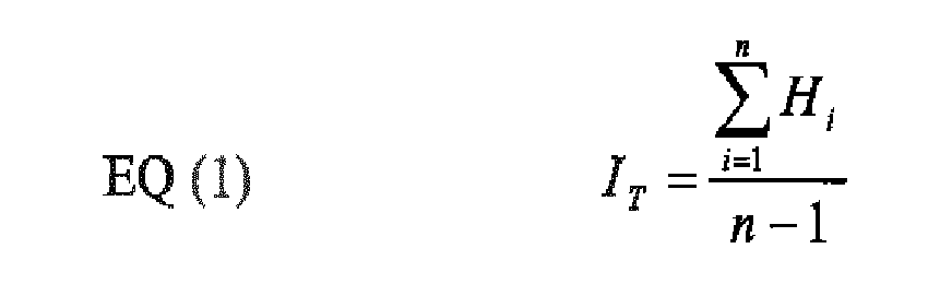
- And the output of any given
input port 112 may be determined by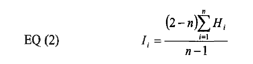
- Where:
- It is the total output from all
input ports 112 combined - Ii is a total output from a the ith input port;
- n is a total number of input ports;
- Hi is average of measures taken while the ith input port is blocked.
- Thus, the
system 100 described herein enables gas sample data to be collected fromchamber 110 while theinput ports 112 are blocked in a pseudo-random fashion. Theprocessing device 160 may then determine a characteristic (i.e. a composition) of the gas associated with any giveninput port 112. This output may be stored in a computer-readable medium such asmemory 130 or presented on a user interface, thereby allowing a user to ascertain information about asingle gas source 130 in a multi-source system, thereby eliminate the need for multiple expensive sensors and the power and weight requirements needed to support the sensors. - While various embodiments have been described, those skilled in the art will recognize modifications or variations which might be made without departing from the present disclosure. For example, while the
processing device 160 is described as a fully functioning computer system, it will be recognized that theprocessing device 160 may be embodied as a specialized controller, e.g., an application specific integrated circuit (ASIC) or a field programmable gate array (FPGA). - In some embodiments a
system 100 may be incorporated into compartments of on anaircraft 700, such as an airplane, helicopter, spacecraft or the like. In alternate embodiments asystem 100 may be incorporated into a ground-based vehicle such as a truck, tank, train, or the like, or on a water-based vehicle such as a ship. In further embodiments asystem 100 may be incorporated into a land-based device or system. - Clause 1: A system to monitor an output of a gas source, comprising: a chamber comprising a plurality of input ports configured to receive a flow of gas from a plurality of gas sources; means for repeatedly: temporarily blocking one of the plurality of input ports; detecting the input port that is blocked; sampling, from a sensor, a characteristic of the gas in the chamber; and storing data from the sensor in a memory in association with an indicator of which one of the plurality of input ports is blocked.
- Clause 2: The system of clause 1, wherein: the chamber comprises a plurality of sloped surfaces, wherein the input ports are positioned on respective sloped surfaces; and the means for repeatedly blocking one of the plurality of input ports for a period of time comprises a ball which rolls over the plurality of sloped surfaces.
- Clause 3: The system of clause 1, wherein: the chamber comprises a plurality of structures which define a plurality of discrete sections, wherein the input ports are positioned in the respective sections; and the means for repeatedly blocking, one of the plurality of input ports for a period of time comprises a ball which rolls into one of the plurality of discrete sections.
- Clause 4: The detection system of clause 1, wherein the means for repeatedly blocking one of the plurality of input ports for a period of time comprises a network of controllable valves.
- Clause 5: The detection system of clause 1, wherein the means for detecting which one of the plurality of input ports is blocked comprises a Hall effect position sensor.
- Clause 6: The system of clause 1, wherein the means for detecting a property of the gas in the chamber comprises a gas sensor.
- Clause 7: The system of clause 1, further comprising means to determine a characteristic of a gas from one of the plurality of input ports from the data.
- Clause 8: The system of clause 1, wherein the means to determine an output from the one of the plurality of input ports from the data comprises a processor-based device comprising logic, at least partially including hardware logic, to compute:

where:- Ii is a total output from a the ith input port;
- n is a total number of input ports;
- Hi is average of measures taken while the ith input port is blocked.
- Clause 9: An aircraft comprising: a system to monitor an output of a gas source on the aircraft, comprising: a chamber comprising a plurality of input ports to receive gas from a plurality of gas sources; means for repeatedly: temporarily blocking one of the plurality of input ports; detecting which one of the plurality of input ports is blocked; sampling, from a sensor, a characteristic of the gas in the chamber; and storing data from the sensor in a memory in association with an indicator of which one of the plurality of input ports is blocked.
- Clause 10: The aircraft of clause 9, wherein: the chamber comprises a plurality of sloped surfaces, wherein the input ports are positioned on respective sloped surfaces; and the means for repeatedly blocking one of the plurality of input ports for a period of time comprises a ball which rolls over the plurality of sloped surfaces.
- Clause 11: The aircraft of clause 9, wherein: the chamber comprises a plurality of structures which define a plurality of discrete sections, wherein the input ports are positioned in the respective sections; and the means for repeatedly blocking one of the plurality of input ports for a period of time comprises a ball which rolls into one of the plurality of discrete sections.
- Clause 12: The aircraft of clause 9, wherein the means for repeatedly blocking, in a pseudo-random or ordered fashion, one of the plurality of input ports for a period of time comprises a network of controllable valves.
- Clause 13: The aircraft of clause 9, wherein the means for detecting which one of the plurality of input ports is blocked comprises a Hall effect position sensor.
- Clause 14: The aircraft of clause 9, wherein the means for collecting data from a plurality of samples from the enclosure while the one of the plurality of input ports is blocked comprises a gas sensor to collect gas samples from the enclosure.
- Clause 15: The aircraft of clause 9, further comprising means to determine a characteristic of a gas from the one of the plurality of input ports from the data.
- Clause 16: The aircraft of clause 9, wherein the means to determine an output from the one of the plurality of input ports from the data comprises a processor-based device comprising logic, at least partially including hardware logic, to compute:

where:- Ii is a total output from a the ith input port;
- n is a total number of input ports;
- Hi is average of measures taken while the ith input port is blocked.
- Clause 17: A method to monitor an output of a gas source, comprising: receiving inputs from a plurality of gas sources in a plurality of input ports in a chamber; repeatedly: temporarily blocking one of the plurality of input ports; detecting which one of the plurality of input ports is blocked; sampling, from a sensor, a characteristic of the gas in the chamber; and storing data from the sensor in a memory in association with an indicator of which one of the plurality of input ports is blocked.
- Clause 18: The method of clause 17, further comprising determining a characteristic of a gas from the one of the plurality of input ports from the data.
- Clause 19: The method of clause 18, wherein: the chamber comprises a plurality of structures which define a plurality of discrete sections, wherein the input ports are positioned in the respective sections; and blocking one of the plurality of input ports for a period of time comprises moving a ball which rolls into one of the plurality of discrete sections.
- Clause 20: The method of clause 18, wherein determining an output from the one of the plurality of input ports from the data comprises computing:

- where: Ii is a total output from a the ith input port; n is a total number of input ports;
- Hi is average of measures taken while the ith input port is blocked.
- The examples illustrate the various embodiments and are not intended to limit the present disclosure. Therefore, the description and claims should be interpreted liberally with only such limitation as is necessary in view of the pertinent prior art.
Claims (10)
- A system to monitor an output of a gas source, comprising:a chamber comprising a plurality of input ports configured to receive a flow of gas from a plurality of gas sources;means for repeatedly:temporarily blocking one of the plurality of input ports;detecting the input port that is blocked;sampling, from a sensor, a characteristic of the gas in the chamber; andstoring data from the sensor in a memory in association with an indicator of which one of the plurality of input ports is blocked.
- The system of claim 1, wherein:the chamber comprises a plurality of sloped surfaces, wherein the input ports are positioned on respective sloped surfaces; andthe means for repeatedly blocking one of the plurality of input ports for a period of time comprises a ball which rolls over the plurality of sloped surfaces.
- The system of claims 1-2, wherein:the chamber comprises a plurality of structures which define a plurality of discrete sections, wherein the input ports are positioned in the respective sections; andthe means for repeatedly blocking, one of the plurality of input ports for a period of time comprises a ball which rolls into one of the plurality of discrete sections.
- The system of claims 1-3, wherein the means for repeatedly blocking one of the plurality of input ports for a period of time comprises a network of controllable valves.
- The system of claims 1 -4, wherein the means for detecting which one of the plurality of input ports is blocked comprises a Hall effect position sensor.
- The system of claims 1-5, wherein the means for detecting a property of the gas in the chamber comprises a gas sensor.
- An aircraft comprising:a system to monitor an output of a gas source on the aircraft, comprising:which one of the plurality of input ports is blocked.a chamber comprising a plurality of input ports to receive gas from a plurality of gas sources;means for repeatedly:temporarily blocking one of the plurality of input ports;detecting which one of the plurality of input ports is blocked;sampling, from a sensor, a characteristic of the gas in the chamber; andstoring data from the sensor in a memory in association with an indicator of
- The aircraft of claim 7, wherein:the chamber comprises a plurality of structures which define a plurality of discrete sections, wherein the input ports are positioned in the respective sections; andthe means for repeatedly blocking one of the plurality of input ports for a period of time comprises a ball which rolls into one of the plurality of discrete sections.
- The aircraft of claims 7-8, wherein a means for collecting data from a plurality of samples from an enclosure while the one of the plurality of input ports is blocked comprises a gas sensor to collect gas samples from the enclosure.
- A method to monitor an output of a gas source, comprising:receiving inputs from a plurality of gas sources in a plurality of input ports in a chamber;repeatedly:temporarily blocking one of the plurality of input ports;detecting which one of the plurality of input ports is blocked;sampling, from a sensor, a characteristic of the gas in the chamber; andstoring data from the sensor in a memory in association with an indicator of which one of the plurality of input ports is blocked.
Applications Claiming Priority (1)
| Application Number | Priority Date | Filing Date | Title |
|---|---|---|---|
| US14/044,494 US9442048B2 (en) | 2013-10-02 | 2013-10-02 | Gas sensing system and method |
Publications (2)
| Publication Number | Publication Date |
|---|---|
| EP2857836A1 true EP2857836A1 (en) | 2015-04-08 |
| EP2857836B1 EP2857836B1 (en) | 2016-01-20 |
Family
ID=51359332
Family Applications (1)
| Application Number | Title | Priority Date | Filing Date |
|---|---|---|---|
| EP14181818.7A Active EP2857836B1 (en) | 2013-10-02 | 2014-08-21 | Gas sensing system and method |
Country Status (7)
| Country | Link |
|---|---|
| US (1) | US9442048B2 (en) |
| EP (1) | EP2857836B1 (en) |
| JP (1) | JP6399842B2 (en) |
| CN (1) | CN104515835B (en) |
| AU (1) | AU2014208198B2 (en) |
| BR (1) | BR102014020101B1 (en) |
| CA (1) | CA2857822C (en) |
Citations (2)
| Publication number | Priority date | Publication date | Assignee | Title |
|---|---|---|---|---|
| US4345610A (en) * | 1979-04-20 | 1982-08-24 | Herter Martin | Process and device for the mixing of gases |
| GB2239952A (en) * | 1989-12-15 | 1991-07-17 | Para Mech Ltd | Sensor system eg for chlorofluorocarbons (CFCs) |
Family Cites Families (15)
| Publication number | Priority date | Publication date | Assignee | Title |
|---|---|---|---|---|
| US5293771A (en) * | 1992-09-01 | 1994-03-15 | Ridenour Ralph Gaylord | Gas leak sensor system |
| US6125710A (en) * | 1997-04-15 | 2000-10-03 | Phoenix Controls Corporation | Networked air measurement system |
| US6241950B1 (en) * | 1998-02-13 | 2001-06-05 | Airxpert Systems, Inc. | Fluid sampling system |
| US7049975B2 (en) * | 2001-02-02 | 2006-05-23 | Fisher Controls International Llc | Reporting regulator for managing a gas transportation system |
| US6634598B2 (en) * | 2001-11-28 | 2003-10-21 | Kenneth Susko | On-board fuel inerting system |
| JP2003291894A (en) * | 2002-04-08 | 2003-10-15 | Shimadzu Corp | Air conditioner for aircraft |
| US7216556B2 (en) * | 2004-09-23 | 2007-05-15 | Aircuity, Inc. | Tubing for transporting air samples in an air monitoring system |
| US7360461B2 (en) * | 2004-09-23 | 2008-04-22 | Aircuity, Inc. | Air monitoring system having tubing with an electrically conductive inner surface for transporting air samples |
| DK1856454T3 (en) * | 2005-03-10 | 2017-09-11 | Aircuity Incorporated | MULTI-POINT AIR TESTING SYSTEM WITH COMMON SENSORS TO PROVIDE MIXED AIR QUALITY PARAMETER INFORMATION FOR MONITORING AND BUILDING MANAGEMENT |
| JP4755861B2 (en) * | 2005-07-14 | 2011-08-24 | ダイダン株式会社 | Air conditioning system |
| US7421911B2 (en) * | 2005-12-20 | 2008-09-09 | Desrochers Eric M | Duct probe assembly system for multipoint air sampling |
| US7570349B2 (en) * | 2007-05-15 | 2009-08-04 | The Boeing Company | Cars/absorption dual mode electro-optic sensor |
| US20110308453A1 (en) | 2008-01-31 | 2011-12-22 | Applied Materials, Inc. | Closed loop mocvd deposition control |
| CN102661834B (en) * | 2011-12-30 | 2015-09-09 | 昆山和智电气设备有限公司 | The online leak locator of high sensitive multipath SF6 and detection method thereof |
| US9109981B2 (en) * | 2013-03-15 | 2015-08-18 | Aircuity, Inc. | Methods and apparatus for indoor air contaminant monitoring |
-
2013
- 2013-10-02 US US14/044,494 patent/US9442048B2/en active Active
-
2014
- 2014-07-23 JP JP2014149536A patent/JP6399842B2/en active Active
- 2014-07-24 CA CA2857822A patent/CA2857822C/en active Active
- 2014-07-29 AU AU2014208198A patent/AU2014208198B2/en active Active
- 2014-08-13 BR BR102014020101-7A patent/BR102014020101B1/en active IP Right Grant
- 2014-08-21 EP EP14181818.7A patent/EP2857836B1/en active Active
- 2014-09-25 CN CN201410495175.4A patent/CN104515835B/en active Active
Patent Citations (2)
| Publication number | Priority date | Publication date | Assignee | Title |
|---|---|---|---|---|
| US4345610A (en) * | 1979-04-20 | 1982-08-24 | Herter Martin | Process and device for the mixing of gases |
| GB2239952A (en) * | 1989-12-15 | 1991-07-17 | Para Mech Ltd | Sensor system eg for chlorofluorocarbons (CFCs) |
Non-Patent Citations (1)
| Title |
|---|
| "Guidelines on GPRS Handset Requirements, Global System for Mobile Communications", December 2002, GSM ASSOCIATION |
Also Published As
| Publication number | Publication date |
|---|---|
| CA2857822C (en) | 2017-02-28 |
| US9442048B2 (en) | 2016-09-13 |
| JP6399842B2 (en) | 2018-10-03 |
| CN104515835A (en) | 2015-04-15 |
| BR102014020101A2 (en) | 2015-09-22 |
| CA2857822A1 (en) | 2015-04-02 |
| US20150090001A1 (en) | 2015-04-02 |
| JP2015072256A (en) | 2015-04-16 |
| CN104515835B (en) | 2018-08-28 |
| AU2014208198A1 (en) | 2015-04-16 |
| EP2857836B1 (en) | 2016-01-20 |
| BR102014020101B1 (en) | 2020-03-31 |
| AU2014208198B2 (en) | 2019-01-17 |
Similar Documents
| Publication | Publication Date | Title |
|---|---|---|
| EP2706386B1 (en) | Method of determining a turbulent condition in an aircraft | |
| US8643509B1 (en) | Methods and systems for providing sloshing alerts and advisories | |
| CN103646535B (en) | Driving Behavior Control System | |
| AU2017387061B2 (en) | Portable moisture analyzer for natural gas | |
| US20230016401A1 (en) | Local electronic environmental detection device | |
| CN110705842A (en) | Chemical industry park dangerous situation sensing method and system based on multi-source data fusion | |
| Xing et al. | Mobile robot multi-sensor unit for unsupervised gas discrimination in uncontrolled environments | |
| EP2857836B1 (en) | Gas sensing system and method | |
| Fernando et al. | Practical validation of unmodified handheld monitors for UAV-based air quality measurements | |
| CN109581289A (en) | Vehicle-mounted fire-fighting rotor wing unmanned aerial vehicle TOA co-located method | |
| CN104567917A (en) | Method for predicting position and speed of variable-step reentry vehicle based on dynamic characteristics | |
| Polyakov et al. | Atmospheric air pollution monitoring using flying robotics | |
| AU2017375903A1 (en) | Safety workbench, mobile laboratory and method | |
| Bartholmai et al. | Monitoring of hazardous scenarios using multi-sensor devices | |
| CN114919468B (en) | A fuel cell engine control method and device based on inertial measurement sensor | |
| Stewart et al. | Atmospheric Chemical Sensing by Unmanned Aerial Vehicles | |
| Poppa et al. | Development of a carbon dioxide monitoring rotorcraft unmanned aerial vehicle | |
| Shiyu et al. | {MC COMMENT: PA CORRECTION} Theoretical study of ullage washing with mixed inert gas in a non-equilibrium state | |
| Hu et al. | Simulation platform of monitoring and tracking micro system for dangerous chemicals transportation | |
| Bartholmai et al. | Monitoring of hazardous scenarios using multi-sensor devices and sensor data fusion | |
| CN103837205B (en) | A kind of on-line monitoring lighter-than-air flight device balloonet volume and the device of richness | |
| Bartholmai et al. | B5. 2-Multi-sensor Systems for Safety-related Monitoring | |
| TR2025023094A2 (en) | AUTONOMOUS FIRE MONITORING UNIT BASED ON COMBUSTION INDICATORS | |
| Nordlund et al. | Probabilistic near mid-air collision avoidance | |
| Graehl | Development of an airborne pollution measurement system |
Legal Events
| Date | Code | Title | Description |
|---|---|---|---|
| PUAI | Public reference made under article 153(3) epc to a published international application that has entered the european phase |
Free format text: ORIGINAL CODE: 0009012 |
|
| 17P | Request for examination filed |
Effective date: 20140821 |
|
| AK | Designated contracting states |
Kind code of ref document: A1 Designated state(s): AL AT BE BG CH CY CZ DE DK EE ES FI FR GB GR HR HU IE IS IT LI LT LU LV MC MK MT NL NO PL PT RO RS SE SI SK SM TR |
|
| AX | Request for extension of the european patent |
Extension state: BA ME |
|
| GRAP | Despatch of communication of intention to grant a patent |
Free format text: ORIGINAL CODE: EPIDOSNIGR1 |
|
| RIC1 | Information provided on ipc code assigned before grant |
Ipc: G01N 33/00 20060101AFI20150708BHEP Ipc: G01N 1/26 20060101ALI20150708BHEP |
|
| INTG | Intention to grant announced |
Effective date: 20150728 |
|
| GRAS | Grant fee paid |
Free format text: ORIGINAL CODE: EPIDOSNIGR3 |
|
| GRAP | Despatch of communication of intention to grant a patent |
Free format text: ORIGINAL CODE: EPIDOSNIGR1 |
|
| INTG | Intention to grant announced |
Effective date: 20151019 |
|
| GRAA | (expected) grant |
Free format text: ORIGINAL CODE: 0009210 |
|
| AK | Designated contracting states |
Kind code of ref document: B1 Designated state(s): AL AT BE BG CH CY CZ DE DK EE ES FI FR GB GR HR HU IE IS IT LI LT LU LV MC MK MT NL NO PL PT RO RS SE SI SK SM TR |
|
| REG | Reference to a national code |
Ref country code: GB Ref legal event code: FG4D |
|
| REG | Reference to a national code |
Ref country code: CH Ref legal event code: EP |
|
| REG | Reference to a national code |
Ref country code: IE Ref legal event code: FG4D |
|
| REG | Reference to a national code |
Ref country code: AT Ref legal event code: REF Ref document number: 771967 Country of ref document: AT Kind code of ref document: T Effective date: 20160215 |
|
| REG | Reference to a national code |
Ref country code: DE Ref legal event code: R096 Ref document number: 602014000789 Country of ref document: DE |
|
| REG | Reference to a national code |
Ref country code: LT Ref legal event code: MG4D Ref country code: NL Ref legal event code: MP Effective date: 20160120 |
|
| REG | Reference to a national code |
Ref country code: AT Ref legal event code: MK05 Ref document number: 771967 Country of ref document: AT Kind code of ref document: T Effective date: 20160120 |
|
| PG25 | Lapsed in a contracting state [announced via postgrant information from national office to epo] |
Ref country code: NL Free format text: LAPSE BECAUSE OF FAILURE TO SUBMIT A TRANSLATION OF THE DESCRIPTION OR TO PAY THE FEE WITHIN THE PRESCRIBED TIME-LIMIT Effective date: 20160120 |
|
| PG25 | Lapsed in a contracting state [announced via postgrant information from national office to epo] |
Ref country code: NO Free format text: LAPSE BECAUSE OF FAILURE TO SUBMIT A TRANSLATION OF THE DESCRIPTION OR TO PAY THE FEE WITHIN THE PRESCRIBED TIME-LIMIT Effective date: 20160420 Ref country code: ES Free format text: LAPSE BECAUSE OF FAILURE TO SUBMIT A TRANSLATION OF THE DESCRIPTION OR TO PAY THE FEE WITHIN THE PRESCRIBED TIME-LIMIT Effective date: 20160120 Ref country code: HR Free format text: LAPSE BECAUSE OF FAILURE TO SUBMIT A TRANSLATION OF THE DESCRIPTION OR TO PAY THE FEE WITHIN THE PRESCRIBED TIME-LIMIT Effective date: 20160120 Ref country code: GR Free format text: LAPSE BECAUSE OF FAILURE TO SUBMIT A TRANSLATION OF THE DESCRIPTION OR TO PAY THE FEE WITHIN THE PRESCRIBED TIME-LIMIT Effective date: 20160421 Ref country code: IT Free format text: LAPSE BECAUSE OF FAILURE TO SUBMIT A TRANSLATION OF THE DESCRIPTION OR TO PAY THE FEE WITHIN THE PRESCRIBED TIME-LIMIT Effective date: 20160120 Ref country code: FI Free format text: LAPSE BECAUSE OF FAILURE TO SUBMIT A TRANSLATION OF THE DESCRIPTION OR TO PAY THE FEE WITHIN THE PRESCRIBED TIME-LIMIT Effective date: 20160120 |
|
| REG | Reference to a national code |
Ref country code: FR Ref legal event code: PLFP Year of fee payment: 3 |
|
| PG25 | Lapsed in a contracting state [announced via postgrant information from national office to epo] |
Ref country code: SE Free format text: LAPSE BECAUSE OF FAILURE TO SUBMIT A TRANSLATION OF THE DESCRIPTION OR TO PAY THE FEE WITHIN THE PRESCRIBED TIME-LIMIT Effective date: 20160120 Ref country code: LV Free format text: LAPSE BECAUSE OF FAILURE TO SUBMIT A TRANSLATION OF THE DESCRIPTION OR TO PAY THE FEE WITHIN THE PRESCRIBED TIME-LIMIT Effective date: 20160120 Ref country code: IS Free format text: LAPSE BECAUSE OF FAILURE TO SUBMIT A TRANSLATION OF THE DESCRIPTION OR TO PAY THE FEE WITHIN THE PRESCRIBED TIME-LIMIT Effective date: 20160520 Ref country code: PT Free format text: LAPSE BECAUSE OF FAILURE TO SUBMIT A TRANSLATION OF THE DESCRIPTION OR TO PAY THE FEE WITHIN THE PRESCRIBED TIME-LIMIT Effective date: 20160520 Ref country code: AT Free format text: LAPSE BECAUSE OF FAILURE TO SUBMIT A TRANSLATION OF THE DESCRIPTION OR TO PAY THE FEE WITHIN THE PRESCRIBED TIME-LIMIT Effective date: 20160120 Ref country code: PL Free format text: LAPSE BECAUSE OF FAILURE TO SUBMIT A TRANSLATION OF THE DESCRIPTION OR TO PAY THE FEE WITHIN THE PRESCRIBED TIME-LIMIT Effective date: 20160120 Ref country code: LT Free format text: LAPSE BECAUSE OF FAILURE TO SUBMIT A TRANSLATION OF THE DESCRIPTION OR TO PAY THE FEE WITHIN THE PRESCRIBED TIME-LIMIT Effective date: 20160120 Ref country code: RS Free format text: LAPSE BECAUSE OF FAILURE TO SUBMIT A TRANSLATION OF THE DESCRIPTION OR TO PAY THE FEE WITHIN THE PRESCRIBED TIME-LIMIT Effective date: 20160120 |
|
| REG | Reference to a national code |
Ref country code: DE Ref legal event code: R097 Ref document number: 602014000789 Country of ref document: DE |
|
| PG25 | Lapsed in a contracting state [announced via postgrant information from national office to epo] |
Ref country code: DK Free format text: LAPSE BECAUSE OF FAILURE TO SUBMIT A TRANSLATION OF THE DESCRIPTION OR TO PAY THE FEE WITHIN THE PRESCRIBED TIME-LIMIT Effective date: 20160120 Ref country code: EE Free format text: LAPSE BECAUSE OF FAILURE TO SUBMIT A TRANSLATION OF THE DESCRIPTION OR TO PAY THE FEE WITHIN THE PRESCRIBED TIME-LIMIT Effective date: 20160120 |
|
| PLBE | No opposition filed within time limit |
Free format text: ORIGINAL CODE: 0009261 |
|
| STAA | Information on the status of an ep patent application or granted ep patent |
Free format text: STATUS: NO OPPOSITION FILED WITHIN TIME LIMIT |
|
| PG25 | Lapsed in a contracting state [announced via postgrant information from national office to epo] |
Ref country code: CZ Free format text: LAPSE BECAUSE OF FAILURE TO SUBMIT A TRANSLATION OF THE DESCRIPTION OR TO PAY THE FEE WITHIN THE PRESCRIBED TIME-LIMIT Effective date: 20160120 Ref country code: SM Free format text: LAPSE BECAUSE OF FAILURE TO SUBMIT A TRANSLATION OF THE DESCRIPTION OR TO PAY THE FEE WITHIN THE PRESCRIBED TIME-LIMIT Effective date: 20160120 Ref country code: SK Free format text: LAPSE BECAUSE OF FAILURE TO SUBMIT A TRANSLATION OF THE DESCRIPTION OR TO PAY THE FEE WITHIN THE PRESCRIBED TIME-LIMIT Effective date: 20160120 Ref country code: RO Free format text: LAPSE BECAUSE OF FAILURE TO SUBMIT A TRANSLATION OF THE DESCRIPTION OR TO PAY THE FEE WITHIN THE PRESCRIBED TIME-LIMIT Effective date: 20160120 |
|
| 26N | No opposition filed |
Effective date: 20161021 |
|
| PG25 | Lapsed in a contracting state [announced via postgrant information from national office to epo] |
Ref country code: BE Free format text: LAPSE BECAUSE OF FAILURE TO SUBMIT A TRANSLATION OF THE DESCRIPTION OR TO PAY THE FEE WITHIN THE PRESCRIBED TIME-LIMIT Effective date: 20160120 |
|
| PG25 | Lapsed in a contracting state [announced via postgrant information from national office to epo] |
Ref country code: SI Free format text: LAPSE BECAUSE OF FAILURE TO SUBMIT A TRANSLATION OF THE DESCRIPTION OR TO PAY THE FEE WITHIN THE PRESCRIBED TIME-LIMIT Effective date: 20160120 Ref country code: BG Free format text: LAPSE BECAUSE OF FAILURE TO SUBMIT A TRANSLATION OF THE DESCRIPTION OR TO PAY THE FEE WITHIN THE PRESCRIBED TIME-LIMIT Effective date: 20160420 |
|
| PG25 | Lapsed in a contracting state [announced via postgrant information from national office to epo] |
Ref country code: MC Free format text: LAPSE BECAUSE OF FAILURE TO SUBMIT A TRANSLATION OF THE DESCRIPTION OR TO PAY THE FEE WITHIN THE PRESCRIBED TIME-LIMIT Effective date: 20160120 |
|
| REG | Reference to a national code |
Ref country code: IE Ref legal event code: MM4A |
|
| PG25 | Lapsed in a contracting state [announced via postgrant information from national office to epo] |
Ref country code: IE Free format text: LAPSE BECAUSE OF NON-PAYMENT OF DUE FEES Effective date: 20160821 |
|
| REG | Reference to a national code |
Ref country code: FR Ref legal event code: PLFP Year of fee payment: 4 |
|
| PG25 | Lapsed in a contracting state [announced via postgrant information from national office to epo] |
Ref country code: LU Free format text: LAPSE BECAUSE OF NON-PAYMENT OF DUE FEES Effective date: 20160821 |
|
| REG | Reference to a national code |
Ref country code: CH Ref legal event code: PL |
|
| PG25 | Lapsed in a contracting state [announced via postgrant information from national office to epo] |
Ref country code: LI Free format text: LAPSE BECAUSE OF NON-PAYMENT OF DUE FEES Effective date: 20170831 Ref country code: CH Free format text: LAPSE BECAUSE OF NON-PAYMENT OF DUE FEES Effective date: 20170831 |
|
| PG25 | Lapsed in a contracting state [announced via postgrant information from national office to epo] |
Ref country code: HU Free format text: LAPSE BECAUSE OF FAILURE TO SUBMIT A TRANSLATION OF THE DESCRIPTION OR TO PAY THE FEE WITHIN THE PRESCRIBED TIME-LIMIT; INVALID AB INITIO Effective date: 20140821 |
|
| PG25 | Lapsed in a contracting state [announced via postgrant information from national office to epo] |
Ref country code: CY Free format text: LAPSE BECAUSE OF FAILURE TO SUBMIT A TRANSLATION OF THE DESCRIPTION OR TO PAY THE FEE WITHIN THE PRESCRIBED TIME-LIMIT Effective date: 20160120 Ref country code: MK Free format text: LAPSE BECAUSE OF FAILURE TO SUBMIT A TRANSLATION OF THE DESCRIPTION OR TO PAY THE FEE WITHIN THE PRESCRIBED TIME-LIMIT Effective date: 20160120 Ref country code: MT Free format text: LAPSE BECAUSE OF NON-PAYMENT OF DUE FEES Effective date: 20160831 |
|
| REG | Reference to a national code |
Ref country code: FR Ref legal event code: PLFP Year of fee payment: 5 |
|
| PG25 | Lapsed in a contracting state [announced via postgrant information from national office to epo] |
Ref country code: TR Free format text: LAPSE BECAUSE OF FAILURE TO SUBMIT A TRANSLATION OF THE DESCRIPTION OR TO PAY THE FEE WITHIN THE PRESCRIBED TIME-LIMIT Effective date: 20160120 Ref country code: AL Free format text: LAPSE BECAUSE OF FAILURE TO SUBMIT A TRANSLATION OF THE DESCRIPTION OR TO PAY THE FEE WITHIN THE PRESCRIBED TIME-LIMIT Effective date: 20160120 |
|
| P01 | Opt-out of the competence of the unified patent court (upc) registered |
Effective date: 20230516 |
|
| PGFP | Annual fee paid to national office [announced via postgrant information from national office to epo] |
Ref country code: DE Payment date: 20250827 Year of fee payment: 12 |
|
| PGFP | Annual fee paid to national office [announced via postgrant information from national office to epo] |
Ref country code: GB Payment date: 20250827 Year of fee payment: 12 |
|
| PGFP | Annual fee paid to national office [announced via postgrant information from national office to epo] |
Ref country code: FR Payment date: 20250825 Year of fee payment: 12 |