EP2857628B1 - Cellular shade assembly and method for constructing same - Google Patents
Cellular shade assembly and method for constructing same Download PDFInfo
- Publication number
- EP2857628B1 EP2857628B1 EP14185195.6A EP14185195A EP2857628B1 EP 2857628 B1 EP2857628 B1 EP 2857628B1 EP 14185195 A EP14185195 A EP 14185195A EP 2857628 B1 EP2857628 B1 EP 2857628B1
- Authority
- EP
- European Patent Office
- Prior art keywords
- segment
- back face
- front face
- face
- cell structures
- Prior art date
- Legal status (The legal status is an assumption and is not a legal conclusion. Google has not performed a legal analysis and makes no representation as to the accuracy of the status listed.)
- Active
Links
Images


Classifications
-
- E—FIXED CONSTRUCTIONS
- E06—DOORS, WINDOWS, SHUTTERS, OR ROLLER BLINDS IN GENERAL; LADDERS
- E06B—FIXED OR MOVABLE CLOSURES FOR OPENINGS IN BUILDINGS, VEHICLES, FENCES OR LIKE ENCLOSURES IN GENERAL, e.g. DOORS, WINDOWS, BLINDS, GATES
- E06B9/00—Screening or protective devices for wall or similar openings, with or without operating or securing mechanisms; Closures of similar construction
- E06B9/24—Screens or other constructions affording protection against light, especially against sunshine; Similar screens for privacy or appearance; Slat blinds
- E06B9/26—Lamellar or like blinds, e.g. venetian blinds
- E06B9/262—Lamellar or like blinds, e.g. venetian blinds with flexibly-interconnected horizontal or vertical strips; Concertina blinds, i.e. upwardly folding flexible screens
- E06B2009/2627—Cellular screens, e.g. box or honeycomb-like
Definitions
- Cellular shades have become a popular type of window covering in residential and commercial applications. The shades are aesthetically attractive and also provide improved insulation across a window or other type of opening due to their cellular construction.
- Cellular shades have assumed various forms, including a plurality of longitudinally extending tubes made of a flexible or semi-rigid material.
- Cellular shades can, for instance, be mounted at the top of a door or window for extending across an architectural opening. When the shade is in an expanded state, the tubes cover the opening. The shade can be retracted or drawn into a contracted state wherein the tubes collapse into a stack. When viewed from the front (i.e., interior of a room) this stack may have an appearance similar to stacked slats of a Venetian blind.
- the width of the stack is half of the overall perimeter of the cell and projects from the glass side to the room side since the cords are normally disposed through the connecting point between each cell.
- DE 20 2008 003195 describes a honeycomb structure of an optical shutter having textile-related inner and outer visor pieces, which have at the sides markedly pronounced edges, which lead to an upper and a lower surface wherein the upper surface is shorter than the corresponding lower and the other longer than the associated lower.
- the assembly of the inner and outer visor pieces takes place in the opposite direction and they are mounted one above the other, in each case a bottom surface having an upper surface being joined by center offset gluing, so that a light-exposed light-blocking outer and formed an inwardly facing decorative surface.
- a cellular shade is produced from two sheets of material which are pleated and then glued at the apex of the folds to form the cells.
- cellular shades can be produced by joining together multiple flat sheets of material along alternating glue lines between each flat sheet.
- a cellular shade can be produced by attaching a series of slats between two spaced apart sheets of material.
- a cellular shade in which each cell has a front section and a rear section.
- the sections are configured to form a V-shape or a C-shape and are positioned so that the free edges are opposite one another.
- a section of swirled strands is connected between one free edge of the front section and one free edge of the rear section.
- a second section of swirled strands can be connected between the second edge of the front section and the second edge of the rear section to form a closed cell.
- the cells are connected to one another by a pair of glue beads adjacent or on top of the section of swirled strands.
- the present disclosure is directed to further improvements in cellular shades. More particularly, the present disclosure is directed to an improved cell structure and method for constructing a cellular shade.
- the present disclosure is directed to a cellular shade comprised of a plurality of closed cell structures.
- the closed cell structures are made from separate pieces of material allowing for the cell structures to include a face fabric that is different from a back fabric if desired.
- the front face and the back face are positioned in an offset relationship with respect to a vertical axis that intersects the cells when the cells are in an open position. Positioning the front face and back face in an offset relationship allows for the production of a cellular shade having improved strength characteristics. In particular, the construction provides good attachment strength between adjacent cell structures.
- a cellular shade as defined in appended claim 1.
- cell structures can be configured such that the offset nature of the materials is not noticeable when viewing the shade.
- the cells can be produced so as to have a substantially symmetrical look.
- the front face can include a first segment separated from a second segment by a first fold line.
- the back face can include a corresponding first segment separated from a corresponding second segment by a second fold line.
- the front face and back face are offset such that the first segment of the front face has a length less than the length of the second segment of the front face and the first segment of the back face can have a length greater than the length of the second segment of the back face.
- the first segment of the front face is above the second segment of the front face in the longitudinal direction and the first segment of the back face is above the second segment of the back face in the longitudinal direction.
- the cell structures can be made such that the second segment of the front face is above the first segment of the front face in the longitudinal direction and the second segment of the back face is above the first segment of the back face in the longitudinal direction.
- the cellular shade can further include a lift system that is configured for vertically drawing the closed cell structures from a fully expanded configuration into a fully retracted configuration.
- the lift system for instance, may include a plurality of lift cords that are connected to the closed cell structures.
- the cellular shade can further include a head rail assembly for mounting the shade into an architectural opening. The head rail assembly may also be in operative association with the lift system for retracting and extending the cellular shade.
- the back face of each cellular structure comprises two separate pieces of material joined together along the second fold line.
- a tab may be formed where the two pieces of material are joined together.
- the tab may extend transversely from the cellular structures about mid-height and can be attached to the vertical cords of the lift system.
- the closed cell structures collapse into a flat profile. More particularly, the plurality of closed cell structures can hang from the lift cords in a vertical and adjacently disposed orientation whereby upper edges of the collapsed closed cell structures are adjacent and oriented in an upward vertical direction and bottom edges of the collapsed cell structures are adjacent and oriented in a downward vertical direction.
- the upper edges for instance, can be defined by the first fold lines while the bottom edges can be defined by the second fold lines.
- the lift cords may extend through the center of the cellular structures. In this arrangement, when the cellular shade is in the fully retracted configuration, the cellular structures collapse and form a horizontally stacked arrangement.
- one of the advantages of the present disclosure is the ability to produce closed cell structures in which the face fabric is different from the back fabric.
- the color of the face fabric may be different than the color of the back fabric.
- the face fabric may have a different opacity and/or transmittance than the back fabric.
- the back fabric can be made from a material that allows substantial amounts of light to transmit through the material, while the face fabric can be made from a material that allows less light to pass through the material in comparison to the back fabric or may substantially block light from passing through the material. Adjusting the opacity and/or the transmittance of the face fabric and the back fabric can produce a shade product that illuminates a room in a desired way.
- the back face of the cellular structures may have a transmittance at a wavelength of 500 nanometers that is at least 50% greater than the transmittance of the front face at 500 nanometers.
- the back face can have a light transmittance at a wavelength of 500 nanometers of at least 40%.
- the back face can be made from a shear material that allows light to pass through the material and illuminate the front face when the shade is exposed to sunlight.
- the present disclosure is directed to cellular shade assemblies that can be mounted in an architectural opening, such as a window or door, for blocking light, providing privacy, increasing the aesthetic appeal of a room and/or allowing a desired amount of light into a room.
- the present disclosure is particularly directed to different methods for constructing closed cell structures that are used to produce cellular shade assemblies.
- the closed cell structures of the present disclosure offer various advantages and benefits.
- the closed cell structures are made from multiple pieces of fabric that allow for different fabrics to be combined together in producing the cell structures.
- the different fabrics can be combined for increasing the overall aesthetic appeal of the product and/or for adjusting the amount of light that passes through the shade assembly.
- cell structures of the present disclosure have excellent strength properties when sequentially connected together increasing the overall strength of the product.
- FIG. 1 a portion of the shade assembly is shown, which can be mounted within a window similar to the embodiment illustrated in Fig. 6 .
- the shade assembly 10 is not limited in its particular use as a window or door shade, and may be used in any application as a covering, partition, shade, or the like in any type of architectural opening in a building or structure.
- the shade assembly 10 includes a plurality of closed cell structures 12 that are disposed longitudinally along a width dimension of the shade assembly so as to extend across a window or other opening.
- the closed cell structures 12 are aligned vertically one above another with juncture lines 16 defined between adjacent cell structures 12.
- the shade assembly 10 generally includes a front 14 that is intended to face the interior of a room or building and a back 15 that is intended to face a window or the outside environment.
- each of the cell structures 12 is “closed” in that the structure is defined by a continuous, unbroken circumferential wall.
- the cell structures 12 are formed from a material or fabric that may be flexible or semi-rigid.
- the cell structures 12 can be made from a single type of material or fabric or can be constructed from different types of materials or fabrics depending upon the particular application.
- a "flexible” material is capable of being folded or flexed, and includes such materials as woven, knitted, or non-woven fabrics, vinyl or film sheets, cords of natural or synthetic fibers, monofilaments, and the like.
- a “semi-rigid” material is somewhat stiffer, but is still flexible or foldable to some degree. Examples of such materials include resin reinforced fabrics, polyvinyl chloride, and so forth. It should be readily appreciated that the present disclosure is not limited to the type of material used to form the cell structures.
- the shade assembly 10 shown in Fig. 1 can include a head rail that is adapted to be mounted to the frame structure of a window, door or other type of opening.
- the head rail may include an extruded longitudinally extending component that includes any number of chambers, channels or other features necessary for incorporating a lift system, cords, pulleys and the like, for raising and lowering the shade assembly 10 between a fully expanded configuration as illustrated in Fig. 1 and 2 and a fully contracted configuration as illustrated in Fig. 3 .
- the closed cell structures 12 generally have a hexagon-like shape. As shown in Fig.
- each cell structure 12 includes a first fold line 20 located along a front face 22 and an opposing second fold line 24 located along a back face 26.
- the fold lines 20 and 24 result in a unique three-dimensional expansion of the front face 22 and the back face 26 resulting in the hexagon-like shape.
- the cell structures 12 may not include the fold lines 20 and 24.
- the front face 22 and the back face 26 will have an essentially flat, vertical profile.
- the first fold line 20 along the front face 22 and the second fold line 24 along the back face 26 cause the cell structures 12 to close when the shade assembly is contracted such that the front face 22 collapses against itself along the fold line 20.
- the back face 26 also collapses upon itself along the second fold line 24.
- the shade assembly can include a lift system.
- Various cord-type lift systems are well known in the art, and any one of these types of systems may be configured or utilized for use with the shade assembly 10.
- the lift system includes a plurality of lift cords 32.
- the lift cords 32 are disposed in a vertical line of action intersecting each closed cell structure 12.
- the lift cords 32 extend through the closed cell structures 12 from the top of each cell structure to the bottom of each cell structure and generally lie in a plane that intersects the closed cell structures between a front half and a back half.
- the lift cords 32 may vary in number depending upon the width of the shade assembly 10. For example, at least two lift cords can be spaced over the width of the shade assembly, such as from about two lift cords to about six lift cords.
- the assembly may include a ballast member positioned below a bottommost cell structure 12.
- the ballast member may comprise a bar or other weighted member that extends generally across the width of the shade assembly.
- the lift cords 32 can be attached to the ballast member when present.
- the cell structures 12 collapse into a horizontal stack when the assembly is in a fully contracted configuration as shown in Fig. 3 .
- the stack of cell structures 12 are horizontally oriented in that the first fold lines 20 and the second fold lines 24 extend horizontally between the front 14 and the back 15 of the shade assembly 10.
- the first fold line 20 divides the front face 22 into a first segment 40 and a second segment 42.
- the second fold line 24 divides the back face 26 into a corresponding first segment 44 and a second segment 46.
- the first segment 40 of the front face 22 is shorter in length than the second segment 42 of the front face 22.
- the back face 26, on the other hand, is in an offset relationship with the front face 22.
- the length of the segments 44 and 46 of the back face 26 are reversed with respect to the first and second segments 40 and 42 of the front face 22.
- the first segment 44 of the back face 26 has a length greater than the length of the second segment 46 of the back face 26.
- adjacent cell structures 12 are attached to each other along attachment points 50.
- Each attachment point 50 may comprise, for instance, a bead of adhesive or any other suitable attachment structure, such as stitches.
- the cell structures may be attached to each other along a single attachment point that extends the entire width of the three attachment points illustrated.
- the front face 22 of a cell structure is offset from the back face 26 in a manner such that the front face of a higher cell structure is attached to both the front face and the back face of a lower cell structure, while the back face of the higher cell structure is attached to only the back face of the lower adjacent cell structure.
- This attachment configuration can provide various advantages and benefits, including providing a plurality of sequential interconnected closed cell structures that have excellent strength properties where the cells are connected.
- the attachment points 50 as shown in Fig. 2 not only connect the cellular structures together, but also assist in providing the overall shape of the cells.
- the attachment points for instance, assist in creating the hexagon-like shape of the cell structures without having to create further fold lines in the front face 22 or the back face 26.
- the shape of the cell structures 12 can be modified by increasing or decreasing the width of the attachment points between adjacent cell structures.
- the first segment 40 of the front face 22 generally has a shorter length than the second segment 42, while the first segment 44 generally has a longer length than the second segment 42 of the back face 26. It should be understood, however, that the arrangement may be reversed such that the first segment 40 is longer than the second segment 42 of the front face 22 and the first segment 44 is shorter than the second segment 46 of the back face 26.
- the offset relationship of the front face 22 and the back face 26 can also have an impact on the manner in which the lift cords 32 intersect the cell structures 12.
- the lift cords 32 only intersect the front face 22 at the top of each cell structure and only intersect the back face 26 at the bottom of each cell structure. It is believed that the manner in which the lift cords intersect the cells provides greater dimensional stability, especially in the longitudinal direction.
- the cell structures 12 can be constructed to be substantially symmetrical between the bottom half of the cell and the top half of the cell.
- the top half of the cell structure 12 is symmetrical to the bottom half of the cell structure when viewed about a plane 52 that intersects the cell structure mid-height when the cell structure is in the open position.
- the front face 22 and the back face 26 of each closed cell structure is made from a separate piece of material.
- the front face 22 and the back face 26 can be made from the same type of material or fabric. In other embodiments, however, the front face may be made from a different material than the back face. Different materials or fabrics, for instance, can be combined together to produce a shade assembly having desired characteristics and properties.
- the front face 22 can be made from a material that does not permit significant amounts of light to pass through the material, while the back face 26 can be made from a material that allows much larger quantities of light to pass through the material. In this manner, the front face 22 may appear to illuminate when the shade assembly is in an extended position and light, such as sunlight, is striking the shade from the back side.
- the back face 26 may be made from a fabric having a relatively open weave, such as a shear material made from monofilaments or may comprise a film.
- the front face 22, on the other hand may comprise a woven fabric, a knitted fabric, or a non-woven fabric such as a hydroentangled web.
- the back face can have a light transmittance at a wavelength of 500 nanometers that is at least 50% greater than a transmittance of the front face at 500 nanometers.
- the back face can have a light transmittance at a wavelength of 500 nanometers of at least about 20%, such as at least about 30%, such as at least about 40%, such as at least about 50%, such as at least about 60%, such as even greater than about 70%.
- Light transmittance of a fabric can be tested using a spectrophotometer, such as a JASCO V-570 UV/VIS/NIR spectrophotometer.
- a spectrophotometer such as a JASCO V-570 UV/VIS/NIR spectrophotometer.
- the back face is designed to allow greater amounts of light to pass through the material than the front face. In an alternative embodiment, however, the arrangement may be reversed.
- Opacity can be measured using a Hunter Color Difference Meter and can range from 0 to 100%.
- the opacity of the back face material may be at least 20% less, such as at least 30% less, such as at least 40% less, such as at least 50% less, such as at least 60% less than the front face material or vice versus.
- FIG. 5 Another embodiment of a cellular shade assembly 110 generally made in accordance with the present disclosure is shown.
- the individual closed cell structure 112 that makes up the shade assembly 110 is particularly shown in Fig. 5 .
- the closed cell structure 112 includes a front face 122 that is separate from a back face 126.
- the front face 122 defines a first fold line 120 that separates the front face into a first segment 140 and a second segment 142.
- the back face 126 defines a second fold line 124 that separates the back face into a first segment 144 and a second segment 146.
- the front face 122 is offset from the back face 126.
- the front face 122 of a higher cell is attached to the front face and the back face of a lower cell, while the back face 126 of a higher cell is only attached to the back face of a lower cell along attachment points 150.
- this arrangement may be reversed in an alternative embodiment in which the front face of a higher cell is only attached to the front face of a lower cell, while the back face of a higher cell may be attached to both the front face and back face of a lower cell.
- the back face 126 is separated into two separate pieces of material.
- the first segment 144 is made from a separate piece of material than the second segment 146.
- the first segment 144 is attached to the second segment 146 at bond points 154 forming a tab 156.
- the tab 156 can also be formed along the back face 126 without having to use two separate pieces of material.
- the back face 126 is shorter in length than the front face 122 causing the back face to have a substantially vertical profile when the closed cell structures 112 are in an open and expanded position.
- the cell structure 112 illustrated in Fig. 5 can also be made from different materials.
- the front face 122 can be made from a different material than the back face 126 as described above.
- the first segment 144 of the back face 126 can also be made from a different material than the second segment 146 of the back face 126.
- the front face 122 defines a first fold line 120. In an alternative embodiment, however, the front face 122 may not include a fold line. Instead, the front face may billow outwardly from the back face and may have a drooping aspect as well. The drooping and/or billowing profile may be desired in some applications for providing a unique and aesthetically pleasing appearance.
- the front face 122 may have approximately the same length as the back face 126 such that both faces of the cell have a substantially vertical profile.
- Fig. 6 illustrates a front 114 of the shade assembly
- Fig. 7 illustrates a back 115 of the shade assembly.
- the shade assembly can include a head rail 118 towards the top of the assembly and a ballast member 134 located at the bottom of the assembly.
- the closed cell structures 112 are in a sequential and interconnected relationship, separated by junction lines 116.
- the shade assembly 110 further includes a lift system 130 that includes a plurality of lift cords 132.
- the lift cords 132 are disposed in a vertical line of action that is rearward of the back faces 126 of the closed cell structures 112.
- the lift cords 132 do not extend through the closed cell structures and do not break or penetrate through the closed circumferential wall of the cells.
- the number of lift cords 132 can vary depending upon the particular application.
- the shade assembly 110 includes two parallel lift cords 132 located along the back 115 of the shade assembly 110.
- the lift cords 132 are attached to the tabs 154 of the back faces 126 of the closed cell structures 112. As shown in Fig. 5 , the tabs 156 extend outwardly generally at about the mid-height of each closed cell structure as defined between adjacent juncture lines 116.
- the lift cords 132 may engage with the back faces 126 of the individual cell structures 112 by various means. For instance, the lift cords 132 may pass through a hole or grommet in each of the tabs 132.
- the shade assembly 110 assumes a vertical configuration when fully contracted.
- the plurality of closed cell structures 112 are drawn together and hang essentially vertically from the lift cords 132 in the contracted configuration of the shade assembly.
- the collapsed cell structures 112 have upper edges defined by the second fold lines 124 that are generally defined by the attachment locations with the lift cords. These upper edges are adjacent and oriented in an upward vertical direction.
- the bottom edges defined by the first fold lines 120 of the collapsed cell structures 112 are adjacent and oriented in a downward vertical direction.
- the closed cell structures 12 can be constructed with much larger dimensions in the embodiment illustrated in Figs. 8 through 10 without having to enlarge or increase the depth of the architectural opening.
- the lift cords 132 are actuated by pull cords 158.
- the pull cords 158 may be extensions of the lift cords 132 and can be presented at a front side of the shade assembly 110 for a user's convenience in operating the shade assembly. It should be readily appreciated that any manner of pulley, bearing, guide, and the like may be incorporated into the head rail assembly 118 for this purpose.
- the head rail assembly 118 includes an extruded component defining a longitudinally extending tray 160 in which the lift cords 132 are disposed, as well as any other necessary components of the lifting or control system.
- the head rail assembly 118 further defines a longitudinally extending internal channel 162 that is defined between a back guide member 164 and a front guide member 166.
- This internal channel defines a space in which the upper edges of the collapsed cell structures 112 are drawn and held in an adjacent and vertically oriented configuration in the fully contracted state of the shade assembly 110.
- the internal channel 162 may be defined by any manner of structure that is formed integrally or attached to the head rail assembly 118.
- a separate retaining channel 168 may also be defined in the head rail.
- this retaining channel 168 is defined between the front guide member 166 and a front panel 170.
- the front panel 170 may also define the front face of the head rail assembly 118 that is visible from the front of the shade assembly 110 and, in this regard, may have any desired length or aesthetically pleasing configuration.
- the front panel 170 may include a curved bottom lip 172 that is oriented towards a curved lip of the front guide member 166.
- a retaining bar, rod or other member 174 is disposed longitudinally within the retaining channel 168 and serves as the anchor attachment location of the cell structures 112 to the head rail assembly 118.
- the uppermost cell structure 112 includes an extension segment 176 that is adhered or otherwise attached to the retaining bar 174.
- the material that defines the front face 122 of the uppermost cell structure 112 also defines the head rail extension segment 176. This material may also wrap around the bar 174 and extend onto the front face of the panel 170. In this manner, the material that defines the cell structures 112 may also act as a decorative covering to the front panel 170, thus eliminating the requirement for a separate valance or similar device.
Description
- Cellular shades have become a popular type of window covering in residential and commercial applications. The shades are aesthetically attractive and also provide improved insulation across a window or other type of opening due to their cellular construction. Cellular shades have assumed various forms, including a plurality of longitudinally extending tubes made of a flexible or semi-rigid material. Cellular shades can, for instance, be mounted at the top of a door or window for extending across an architectural opening. When the shade is in an expanded state, the tubes cover the opening. The shade can be retracted or drawn into a contracted state wherein the tubes collapse into a stack. When viewed from the front (i.e., interior of a room) this stack may have an appearance similar to stacked slats of a Venetian blind. Typically, the width of the stack is half of the overall perimeter of the cell and projects from the glass side to the room side since the cords are normally disposed through the connecting point between each cell.
DE 20 2008 003195 describes a honeycomb structure of an optical shutter having textile-related inner and outer visor pieces, which have at the sides markedly pronounced edges, which lead to an upper and a lower surface wherein the upper surface is shorter than the corresponding lower and the other longer than the associated lower. The assembly of the inner and outer visor pieces takes place in the opposite direction and they are mounted one above the other, in each case a bottom surface having an upper surface being joined by center offset gluing, so that a light-exposed light-blocking outer and formed an inwardly facing decorative surface. - In the past, individual cells in a cellular shade have been constructed using various techniques and methods. The construction of cellular shades, for instance, is described in
U.S. Patent Nos. 6,767,615 ;4,861,404 ;4,677,012 ;5,701,940 ;5,691,031 ;4,603,072 ;4,732,630 ;4,388,354 ;5,228,936 ;5,339,882 ;6,068,039 ;6,033,504 ; and5,753,338 . - For example, in one embodiment, a cellular shade is produced from two sheets of material which are pleated and then glued at the apex of the folds to form the cells. In an alternative embodiment, cellular shades can be produced by joining together multiple flat sheets of material along alternating glue lines between each flat sheet. In still another embodiment, a cellular shade can be produced by attaching a series of slats between two spaced apart sheets of material.
- In another embodiment, a cellular shade can be produced in which each cell has a front section and a rear section. The sections are configured to form a V-shape or a C-shape and are positioned so that the free edges are opposite one another. A section of swirled strands is connected between one free edge of the front section and one free edge of the rear section. If desired, a second section of swirled strands can be connected between the second edge of the front section and the second edge of the rear section to form a closed cell. The cells are connected to one another by a pair of glue beads adjacent or on top of the section of swirled strands.
- The present disclosure is directed to further improvements in cellular shades. More particularly, the present disclosure is directed to an improved cell structure and method for constructing a cellular shade.
- The present disclosure is directed to a cellular shade comprised of a plurality of closed cell structures. As will be described in greater detail below, the closed cell structures are made from separate pieces of material allowing for the cell structures to include a face fabric that is different from a back fabric if desired. In accordance with the present disclosure, the front face and the back face are positioned in an offset relationship with respect to a vertical axis that intersects the cells when the cells are in an open position. Positioning the front face and back face in an offset relationship allows for the production of a cellular shade having improved strength characteristics. In particular, the construction provides good attachment strength between adjacent cell structures.
- According to the present invention, there is provided a cellular shade as defined in appended claim 1. In other words, even though the front face and the back face are in an offset relationship, cell structures can be configured such that
the offset nature of the materials is not noticeable when viewing the shade. In addition, the cells can be produced so as to have a substantially symmetrical look. - In one embodiment, the front face can include a first segment separated from a second segment by a first fold line. The back face can include a corresponding first segment separated from a corresponding second segment by a second fold line. The front face and back face are offset such that the first segment of the front face has a length less than the length of the second segment of the front face and the first segment of the back face can have a length greater than the length of the second segment of the back face.
- In one embodiment, the first segment of the front face is above the second segment of the front face in the longitudinal direction and the first segment of the back face is above the second segment of the back face in the longitudinal direction. Alternatively, the cell structures can be made such that the second segment of the front face is above the first segment of the front face in the longitudinal direction and the second segment of the back face is above the first segment of the back face in the longitudinal direction.
- The cellular shade can further include a lift system that is configured for vertically drawing the closed cell structures from a fully expanded configuration into a fully retracted configuration. The lift system, for instance, may include a plurality of lift cords that are connected to the closed cell structures. The cellular shade can further include a head rail assembly for mounting the shade into an architectural opening. The head rail assembly may also be in operative association with the lift system for retracting and extending the cellular shade.
- In one embodiment, the back face of each cellular structure comprises two separate pieces of material joined together along the second fold line. A tab may be formed where the two pieces of material are joined together. The tab may extend transversely from the cellular structures about mid-height and can be attached to the vertical cords of the lift system. In the above arrangement, when the cellular shade is in a fully retracted configuration, the closed cell structures collapse into a flat profile. More particularly, the plurality of closed cell structures can hang from the lift cords in a vertical and adjacently disposed orientation whereby upper edges of the collapsed closed cell structures are adjacent and oriented in an upward vertical direction and bottom edges of the collapsed cell structures are adjacent and oriented in a downward vertical direction. The upper edges, for instance, can be defined by the first fold lines while the bottom edges can be defined by the second fold lines.
- In an alternative embodiment, the lift cords may extend through the center of the cellular structures. In this arrangement, when the cellular shade is in the fully retracted configuration, the cellular structures collapse and form a horizontally stacked arrangement.
- As described above, one of the advantages of the present disclosure is the ability to produce closed cell structures in which the face fabric is different from the back fabric. In one embodiment, for instance, the color of the face fabric may be different than the color of the back fabric. In another embodiment, the face fabric may have a different opacity and/or transmittance than the back fabric. For example, the back fabric can be made from a material that allows substantial amounts of light to transmit through the material, while the face fabric can be made from a material that allows less light to pass through the material in comparison to the back fabric or may substantially block light from passing through the material. Adjusting the opacity and/or the transmittance of the face fabric and the back fabric can produce a shade product that illuminates a room in a desired way.
- In one particular embodiment, for instance, the back face of the cellular structures may have a transmittance at a wavelength of 500 nanometers that is at least 50% greater than the transmittance of the front face at 500 nanometers. For instance, the back face can have a light transmittance at a wavelength of 500 nanometers of at least 40%. In one particular embodiment, for instance, the back face can be made from a shear material that allows light to pass through the material and illuminate the front face when the shade is exposed to sunlight.
- Other features and aspects of the present disclosure are discussed in greater detail below.
- A full and enabling disclosure of the present invention, including the best mode thereof to one skilled in the art, is set forth more particularly in the remainder of the specification, including reference to the accompanying figures, in which:
-
Figure 1 is a partial perspective view of one embodiment of a cellular shade assembly made in accordance with the present disclosure; -
Figure 2 is an exploded side view of the cellular structures illustrated inFigure 1 ; -
Figure 3 is another side view of the cellular structures illustrated inFigure 1 shown in a contracted position; -
Figure 4 is a cross-sectional view of one embodiment of a closed cell structure made in accordance with the present disclosure; -
Figure 5 is an exploded side view of another embodiment of a closed cell structure made in accordance with the present disclosure; -
Figure 6 is a perspective view of another embodiment of a cellular shade assembly made in accordance with the present disclosure; -
Figure 7 is a back plan view of the cellular shade assembly illustrated inFigure 6 ; -
Figure 8 is a perspective view of the cellular shade assembly illustrated inFigure 6 shown in a contracted position; -
Figure 9 is a side view of the cellular shade assembly illustrated inFigure 6 shown in a partially contracted position; and -
Figure 10 is a side view of the cellular shade assembly illustrated inFigure 8 . - Repeat use of reference characters in the present specification and drawings is intended to represent the same or analogous features or elements of the present invention.
- It is to be understood by one of ordinary skill in the art that the present discussion is a description of exemplary embodiments only, and is not intended as limiting the broader aspects of the present disclosure.
- In general, the present disclosure is directed to cellular shade assemblies that can be mounted in an architectural opening, such as a window or door, for blocking light, providing privacy, increasing the aesthetic appeal of a room and/or allowing a desired amount of light into a room. The present disclosure is particularly directed to different methods for constructing closed cell structures that are used to produce cellular shade assemblies.
- The closed cell structures of the present disclosure offer various advantages and benefits. For example, the closed cell structures are made from multiple pieces of fabric that allow for different fabrics to be combined together in producing the cell structures. The different fabrics can be combined for increasing the overall aesthetic appeal of the product and/or for adjusting the amount of light that passes through the shade assembly.
- In addition, the cell structures of the present disclosure have excellent strength properties when sequentially connected together increasing the overall strength of the product.
- Referring to
Figs. 1 through 4 , for instance, one embodiment of an expandable andcontractable shade assembly 10 made in accordance with the present disclosure is shown. InFig. 1 , a portion of the shade assembly is shown, which can be mounted within a window similar to the embodiment illustrated inFig. 6 . It should be readily appreciated, however, that theshade assembly 10 is not limited in its particular use as a window or door shade, and may be used in any application as a covering, partition, shade, or the like in any type of architectural opening in a building or structure. - As shown in
Figs. 1 through 4 , theshade assembly 10 includes a plurality ofclosed cell structures 12 that are disposed longitudinally along a width dimension of the shade assembly so as to extend across a window or other opening. Theclosed cell structures 12 are aligned vertically one above another withjuncture lines 16 defined betweenadjacent cell structures 12. Theshade assembly 10 generally includes a front 14 that is intended to face the interior of a room or building and a back 15 that is intended to face a window or the outside environment. - As depicted in the various figures, each of the
cell structures 12 is "closed" in that the structure is defined by a continuous, unbroken circumferential wall. Thecell structures 12 are formed from a material or fabric that may be flexible or semi-rigid. As will be described in greater detail below, thecell structures 12 can be made from a single type of material or fabric or can be constructed from different types of materials or fabrics depending upon the particular application. A "flexible" material is capable of being folded or flexed, and includes such materials as woven, knitted, or non-woven fabrics, vinyl or film sheets, cords of natural or synthetic fibers, monofilaments, and the like. A "semi-rigid" material is somewhat stiffer, but is still flexible or foldable to some degree. Examples of such materials include resin reinforced fabrics, polyvinyl chloride, and so forth. It should be readily appreciated that the present disclosure is not limited to the type of material used to form the cell structures. - Similar to the embodiment illustrated in
Fig. 6 , theshade assembly 10 shown inFig. 1 can include a head rail that is adapted to be mounted to the frame structure of a window, door or other type of opening. The head rail may include an extruded longitudinally extending component that includes any number of chambers, channels or other features necessary for incorporating a lift system, cords, pulleys and the like, for raising and lowering theshade assembly 10 between a fully expanded configuration as illustrated inFig. 1 and2 and a fully contracted configuration as illustrated inFig. 3 . In the embodiments illustrated inFigs. 1 through 4 , theclosed cell structures 12 generally have a hexagon-like shape. As shown inFig. 2 , for instance, eachcell structure 12 includes afirst fold line 20 located along afront face 22 and an opposingsecond fold line 24 located along aback face 26. The fold lines 20 and 24 result in a unique three-dimensional expansion of thefront face 22 and theback face 26 resulting in the hexagon-like shape. In an alternative embodiment, however, thecell structures 12 may not include the fold lines 20 and 24. In this embodiment, thefront face 22 and theback face 26 will have an essentially flat, vertical profile. - As shown in
Fig. 3 , thefirst fold line 20 along thefront face 22 and thesecond fold line 24 along theback face 26 cause thecell structures 12 to close when the shade assembly is contracted such that thefront face 22 collapses against itself along thefold line 20. Similarly, theback face 26 also collapses upon itself along thesecond fold line 24. - In order to adjust the shade assembly between an extended position and a collapsed position, the shade assembly can include a lift system. Various cord-type lift systems are well known in the art, and any one of these types of systems may be configured or utilized for use with the
shade assembly 10. As shown particularly inFig. 1 , the lift system includes a plurality oflift cords 32. Thelift cords 32 are disposed in a vertical line of action intersecting eachclosed cell structure 12. In particular, thelift cords 32 extend through theclosed cell structures 12 from the top of each cell structure to the bottom of each cell structure and generally lie in a plane that intersects the closed cell structures between a front half and a back half. - The
lift cords 32 may vary in number depending upon the width of theshade assembly 10. For example, at least two lift cords can be spaced over the width of the shade assembly, such as from about two lift cords to about six lift cords. - To aid in raising and lowering the
shade assembly 10, the assembly may include a ballast member positioned below abottommost cell structure 12. The ballast member may comprise a bar or other weighted member that extends generally across the width of the shade assembly. Thelift cords 32 can be attached to the ballast member when present. - In the embodiment illustrated in
Figs.1 through 4 , thecell structures 12 collapse into a horizontal stack when the assembly is in a fully contracted configuration as shown inFig. 3 . In particular, the stack ofcell structures 12 are horizontally oriented in that thefirst fold lines 20 and thesecond fold lines 24 extend horizontally between the front 14 and theback 15 of theshade assembly 10. - Referring now to
Fig. 2 , the manner in which theclosed cell structures 12 are constructed is shown in greater detail. As illustrated, thefirst fold line 20 divides thefront face 22 into afirst segment 40 and asecond segment 42. Similarly, thesecond fold line 24 divides theback face 26 into a correspondingfirst segment 44 and asecond segment 46. In accordance with the present disclosure, due to the manner in which adjacent cells are attached together, thefirst segment 40 of thefront face 22 is shorter in length than thesecond segment 42 of thefront face 22. Theback face 26, on the other hand, is in an offset relationship with thefront face 22. In this manner, the length of thesegments back face 26 are reversed with respect to the first andsecond segments front face 22. Specifically, thefirst segment 44 of theback face 26 has a length greater than the length of thesecond segment 46 of theback face 26. - As shown in
Fig. 2 ,adjacent cell structures 12 are attached to each other along attachment points 50. Eachattachment point 50 may comprise, for instance, a bead of adhesive or any other suitable attachment structure, such as stitches. In an alternative embodiment, the cell structures may be attached to each other along a single attachment point that extends the entire width of the three attachment points illustrated. As shown, thefront face 22 of a cell structure is offset from theback face 26 in a manner such that the front face of a higher cell structure is attached to both the front face and the back face of a lower cell structure, while the back face of the higher cell structure is attached to only the back face of the lower adjacent cell structure. This attachment configuration can provide various advantages and benefits, including providing a plurality of sequential interconnected closed cell structures that have excellent strength properties where the cells are connected. - The attachment points 50 as shown in
Fig. 2 not only connect the cellular structures together, but also assist in providing the overall shape of the cells. The attachment points, for instance, assist in creating the hexagon-like shape of the cell structures without having to create further fold lines in thefront face 22 or theback face 26. In this regard, the shape of thecell structures 12 can be modified by increasing or decreasing the width of the attachment points between adjacent cell structures. - In the embodiment illustrated in
Fig. 2 , thefirst segment 40 of thefront face 22 generally has a shorter length than thesecond segment 42, while thefirst segment 44 generally has a longer length than thesecond segment 42 of theback face 26. It should be understood, however, that the arrangement may be reversed such that thefirst segment 40 is longer than thesecond segment 42 of thefront face 22 and thefirst segment 44 is shorter than thesecond segment 46 of theback face 26. - Referring to
Fig. 1 , the offset relationship of thefront face 22 and theback face 26 can also have an impact on the manner in which thelift cords 32 intersect thecell structures 12. For example, as shown inFig. 1 , thelift cords 32 only intersect thefront face 22 at the top of each cell structure and only intersect theback face 26 at the bottom of each cell structure. It is believed that the manner in which the lift cords intersect the cells provides greater dimensional stability, especially in the longitudinal direction. - Although the
front face 22 and theback face 26 are in an offset relationship with respect to each other, thecell structures 12 can be constructed to be substantially symmetrical between the bottom half of the cell and the top half of the cell. For instance, as shown inFig. 4 , the top half of thecell structure 12 is symmetrical to the bottom half of the cell structure when viewed about aplane 52 that intersects the cell structure mid-height when the cell structure is in the open position. - As shown in
Fig. 4 , thefront face 22 and theback face 26 of each closed cell structure is made from a separate piece of material. In one embodiment, thefront face 22 and theback face 26 can be made from the same type of material or fabric. In other embodiments, however, the front face may be made from a different material than the back face. Different materials or fabrics, for instance, can be combined together to produce a shade assembly having desired characteristics and properties. - In one embodiment, for example, the
front face 22 can be made from a material that does not permit significant amounts of light to pass through the material, while theback face 26 can be made from a material that allows much larger quantities of light to pass through the material. In this manner, thefront face 22 may appear to illuminate when the shade assembly is in an extended position and light, such as sunlight, is striking the shade from the back side. In the above embodiment, for example, theback face 26 may be made from a fabric having a relatively open weave, such as a shear material made from monofilaments or may comprise a film. Thefront face 22, on the other hand, may comprise a woven fabric, a knitted fabric, or a non-woven fabric such as a hydroentangled web. - When combining together different fabrics as described above, in one embodiment, the back face can have a light transmittance at a wavelength of 500 nanometers that is at least 50% greater than a transmittance of the front face at 500 nanometers. For instance, the back face can have a light transmittance at a wavelength of 500 nanometers of at least about 20%, such as at least about 30%, such as at least about 40%, such as at least about 50%, such as at least about 60%, such as even greater than about 70%. Light transmittance of a fabric can be tested using a spectrophotometer, such as a JASCO V-570 UV/VIS/NIR spectrophotometer. One procedure for measuring the percent transmittance of a material is described, for instance, in
U.S. Patent No. 7,481,076 , which is incorporated herein by reference. - In the embodiment described above, the back face is designed to allow greater amounts of light to pass through the material than the front face. In an alternative embodiment, however, the arrangement may be reversed.
- Another way to compare the front face material with the back face material is to measure opacity. Opacity can be measured using a Hunter Color Difference Meter and can range from 0 to 100%. In one embodiment, the opacity of the back face material may be at least 20% less, such as at least 30% less, such as at least 40% less, such as at least 50% less, such as at least 60% less than the front face material or vice versus.
- Referring now to
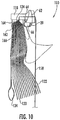
Figs. 5 through 10 , another embodiment of acellular shade assembly 110 generally made in accordance with the present disclosure is shown. The individualclosed cell structure 112 that makes up theshade assembly 110 is particularly shown inFig. 5 . Similar to the embodiment illustrated inFig. 4 , theclosed cell structure 112 includes afront face 122 that is separate from aback face 126. Thefront face 122 defines afirst fold line 120 that separates the front face into afirst segment 140 and asecond segment 142. Theback face 126 defines asecond fold line 124 that separates the back face into afirst segment 144 and asecond segment 146. Similar to the embodiment illustrated inFig. 4 , thefront face 122 is offset from theback face 126. In the embodiment illustrated, for example, thefront face 122 of a higher cell is attached to the front face and the back face of a lower cell, while theback face 126 of a higher cell is only attached to the back face of a lower cell along attachment points 150. As described above, this arrangement may be reversed in an alternative embodiment in which the front face of a higher cell is only attached to the front face of a lower cell, while the back face of a higher cell may be attached to both the front face and back face of a lower cell. - In the embodiment illustrated in
Fig. 5 , theback face 126 is separated into two separate pieces of material. In particular, thefirst segment 144 is made from a separate piece of material than thesecond segment 146. Thefirst segment 144 is attached to thesecond segment 146 atbond points 154 forming atab 156. It should be understood that thetab 156 can also be formed along theback face 126 without having to use two separate pieces of material. As also shown, theback face 126 is shorter in length than thefront face 122 causing the back face to have a substantially vertical profile when theclosed cell structures 112 are in an open and expanded position. - Similar to the embodiment illustrated in
Fig. 4 , thecell structure 112 illustrated inFig. 5 can also be made from different materials. In particular, thefront face 122 can be made from a different material than theback face 126 as described above. In addition, thefirst segment 144 of theback face 126 can also be made from a different material than thesecond segment 146 of theback face 126. - In the embodiment illustrated in
Fig. 5 , thefront face 122 defines afirst fold line 120. In an alternative embodiment, however, thefront face 122 may not include a fold line. Instead, the front face may billow outwardly from the back face and may have a drooping aspect as well. The drooping and/or billowing profile may be desired in some applications for providing a unique and aesthetically pleasing appearance. - As described above, in yet another embodiment, the
front face 122 may have approximately the same length as theback face 126 such that both faces of the cell have a substantially vertical profile. - The
entire shade assembly 110 is more particularly shown inFigs. 6 and7 .Fig. 6 illustrates afront 114 of the shade assembly, whileFig. 7 illustrates a back 115 of the shade assembly. As shown, the shade assembly can include ahead rail 118 towards the top of the assembly and aballast member 134 located at the bottom of the assembly. When in the expanded configuration as shown inFig. 6 , theclosed cell structures 112 are in a sequential and interconnected relationship, separated byjunction lines 116. - The
shade assembly 110 further includes alift system 130 that includes a plurality oflift cords 132. As shown inFig. 7 , in this embodiment, thelift cords 132 are disposed in a vertical line of action that is rearward of the back faces 126 of theclosed cell structures 112. Thus, thelift cords 132 do not extend through the closed cell structures and do not break or penetrate through the closed circumferential wall of the cells. As described above, the number oflift cords 132 can vary depending upon the particular application. In the embodiment illustrated, theshade assembly 110 includes twoparallel lift cords 132 located along the back 115 of theshade assembly 110. - More particularly, the
lift cords 132 are attached to thetabs 154 of the back faces 126 of theclosed cell structures 112. As shown inFig. 5 , thetabs 156 extend outwardly generally at about the mid-height of each closed cell structure as defined between adjacent juncture lines 116. - The
lift cords 132 may engage with the back faces 126 of theindividual cell structures 112 by various means. For instance, thelift cords 132 may pass through a hole or grommet in each of thetabs 132. - One advantage to the embodiment illustrated in
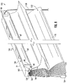
Figs. 5 through 10 is that theshade assembly 110 assumes a vertical configuration when fully contracted. As shown particularly inFigs. 8 through 10 , for instance, the plurality ofclosed cell structures 112 are drawn together and hang essentially vertically from thelift cords 132 in the contracted configuration of the shade assembly. Thecollapsed cell structures 112 have upper edges defined by thesecond fold lines 124 that are generally defined by the attachment locations with the lift cords. These upper edges are adjacent and oriented in an upward vertical direction. Similarly, the bottom edges defined by thefirst fold lines 120 of thecollapsed cell structures 112 are adjacent and oriented in a downward vertical direction. In this manner, when viewed from the front of the shade assembly, the gathered andcollapsed cell structures 112 appear to hang vertically from out of thehead rail assembly 118 in a unique and aesthetically pleasing configuration. In addition, the depth of the vertically oriented and collapsed cell structures is significantly reduced as compared to the horizontal configuration illustrated inFig. 3 . Thus, theclosed cell structures 12 can be constructed with much larger dimensions in the embodiment illustrated inFigs. 8 through 10 without having to enlarge or increase the depth of the architectural opening. - As shown in
Figs. 8 through 10 , thelift cords 132 are actuated bypull cords 158. Thepull cords 158 may be extensions of thelift cords 132 and can be presented at a front side of theshade assembly 110 for a user's convenience in operating the shade assembly. It should be readily appreciated that any manner of pulley, bearing, guide, and the like may be incorporated into thehead rail assembly 118 for this purpose. - In the embodiment illustrated in
Figs. 8 through 10 , thehead rail assembly 118 includes an extruded component defining alongitudinally extending tray 160 in which thelift cords 132 are disposed, as well as any other necessary components of the lifting or control system. Thehead rail assembly 118 further defines a longitudinally extendinginternal channel 162 that is defined between aback guide member 164 and afront guide member 166. This internal channel defines a space in which the upper edges of thecollapsed cell structures 112 are drawn and held in an adjacent and vertically oriented configuration in the fully contracted state of theshade assembly 110. It should be appreciated that theinternal channel 162 may be defined by any manner of structure that is formed integrally or attached to thehead rail assembly 118. - Still referring to the
head rail assembly 118, as shown inFigs. 8 through 10 , aseparate retaining channel 168 may also be defined in the head rail. In the illustrated embodiment, this retainingchannel 168 is defined between thefront guide member 166 and afront panel 170. Thefront panel 170 may also define the front face of thehead rail assembly 118 that is visible from the front of theshade assembly 110 and, in this regard, may have any desired length or aesthetically pleasing configuration. Thefront panel 170 may include a curvedbottom lip 172 that is oriented towards a curved lip of thefront guide member 166. A retaining bar, rod orother member 174 is disposed longitudinally within the retainingchannel 168 and serves as the anchor attachment location of thecell structures 112 to thehead rail assembly 118. Referring toFig. 9 , theuppermost cell structure 112 includes anextension segment 176 that is adhered or otherwise attached to the retainingbar 174. Thus, in the construction of theshade assembly 110, it is only necessary to attach theuppermost cell structure 112 to the retainingbar 174 and then slide the retaining bar into thechannel 168 from an end of the head rail. In one embodiment, the material that defines thefront face 122 of theuppermost cell structure 112 also defines the headrail extension segment 176. This material may also wrap around thebar 174 and extend onto the front face of thepanel 170. In this manner, the material that defines thecell structures 112 may also act as a decorative covering to thefront panel 170, thus eliminating the requirement for a separate valance or similar device. - These and other modifications and variations to the present invention may be practiced by those of ordinary skill in the art, without departing from the spirit and scope of the present invention, which is more particularly set forth in the appended claims. In addition, it should be understood that aspects of the various embodiments may be interchanged both in whole or in part. Furthermore, those of ordinary skill in the art will appreciate that the foregoing description is by way of example only, and is not intended to limit the invention so further described in such appended claims.
Claims (13)
- A cellular shade (10) comprising:a plurality of sequential and interconnected closed cell structures (12) extending in a longitudinal direction, the closed cell structures (12) being aligned vertically one above another with juncture lines (16) defined between adjacent ones of the vertically aligned closed cell structures (12), the cell structures (12) having a collapsed position when the shade is retracted and having an open position when the shade is extended;a lift system configured to adjust the cellular shade between an extended position and a collapsed position; wherein:at least some of the cell structures (12) include a front face (22) and a separate back face (26), and wherein the cell structures (12) are constructed such that the front face (22) is offset from the back face (26), the front face (22) of a higher cell structure (12) being attached to both the front face (22) and the back face (26) of a lower adjacent cell structure (12) and the back face (26) of the higher cell structure (12) being attached only to the back face (26) of the lower adjacent cell structure (12) in a manner that causes a cross-sectional profile of the cell structures (12) to be substantially symmetrical about a plane that intersects the cell structure mid-height when the cell structure (12) is in the open position.
- A cellular shade as defined in claim 1 wherein each front face (22) of each cell structure (12) is made from a separate piece of material and each back face (26) is made from at least one separate piece of material.
- A cellular shade as defined in claim 1 or 2, wherein the front face (22) includes a first segment (40) separated from a second segment (42) by a first fold line (20) and the back face (26) includes a corresponding first segment (44) separated from a corresponding second segment (46) by a second fold line (24).
- A cellular shade as defined in claim 3, wherein the first segment (40) of the front face (22) has a length less than the length of the second segment (42) of the front face (22) and wherein the first segment (44) of the back face (26) has a length greater than the length of the second segment (44) of the back face (26).
- A cellular shade as defined in claim 1, 2, 3 or 4 wherein:the lift system includes a plurality of lift cords (32); andthe lift cords (32) only intersect one of the front face (22) and the back face (26) at the top of each cell structure (12) and only intersect the other of the front face (22) and the back face at the bottom of each cell structure (12).
- A cellular shade as defined in claim 4, wherein the first segment (40) of the front face (22) is above the second segment (42) of the front face (22) in the longitudinal direction and the first segment (44) of the back face (26) is above the second segment (44) of the back face (26) in the longitudinal direction.
- A cellular shade as defined in claim 4, wherein the second segment (42) of the front face (22) is above the first segment (40) of the front face (22) in the longitudinal direction and the second segment (46) of the back face (26) is above the first segment (44) of the back face (26) in the longitudinal direction.
- A cellular shade as defined in claim 3, wherein the first and second segments (114, 146) of the back face (126) comprise two separate pieces of material joined together along the second fold line (124), and wherein a tab (156) is formed where the two pieces of material are joined together.
- A cellular shade as defined in claim 3, wherein, when the shade is in a fully retracted configuration, the plurality of closed cell structures (112) hang in a vertical and adjacently disposed orientation whereby upper edges (124) of the collapsed closed cell structures (112) are adjacent and oriented in an upward vertical direction and bottom edges (120) of the collapsed closed cell structures (112) are adjacent and oriented in a downward vertical direction.
- A cellular shade as defined in claim 9, wherein the collapsed closed cell structures (12) fold along the first fold lines (120) that define the bottom edges and fold along the second fold lines that define the upper edges.
- A cellular shade as defined in claim 1 or 2, wherein the front face (22) is made from a different material than the back face (26).
- A cellular shade as defined in claim 11, wherein the back face (26) has a transmittance at a wavelength of 500 nanometers that is at least 50% greater than a transmittance of the front face (22) at 500 nanometers.
- A cellular shade as defined in claim 11, wherein the back face (26) has a light transmittance at a wavelength of 500 nanometers of at least 40%.
Applications Claiming Priority (2)
| Application Number | Priority Date | Filing Date | Title |
|---|---|---|---|
| US12/985,936 US8459326B2 (en) | 2011-01-06 | 2011-01-06 | Cellular shade assembly and method for constructing same |
| EP12700754.0A EP2661528B1 (en) | 2011-01-06 | 2012-01-05 | Cellular shade assembly and method for constructing same |
Related Parent Applications (2)
| Application Number | Title | Priority Date | Filing Date |
|---|---|---|---|
| EP12700754.0A Division-Into EP2661528B1 (en) | 2011-01-06 | 2012-01-05 | Cellular shade assembly and method for constructing same |
| EP12700754.0A Division EP2661528B1 (en) | 2011-01-06 | 2012-01-05 | Cellular shade assembly and method for constructing same |
Publications (3)
| Publication Number | Publication Date |
|---|---|
| EP2857628A2 EP2857628A2 (en) | 2015-04-08 |
| EP2857628A3 EP2857628A3 (en) | 2015-09-02 |
| EP2857628B1 true EP2857628B1 (en) | 2017-05-17 |
Family
ID=45509748
Family Applications (2)
| Application Number | Title | Priority Date | Filing Date |
|---|---|---|---|
| EP14185195.6A Active EP2857628B1 (en) | 2011-01-06 | 2012-01-05 | Cellular shade assembly and method for constructing same |
| EP12700754.0A Active EP2661528B1 (en) | 2011-01-06 | 2012-01-05 | Cellular shade assembly and method for constructing same |
Family Applications After (1)
| Application Number | Title | Priority Date | Filing Date |
|---|---|---|---|
| EP12700754.0A Active EP2661528B1 (en) | 2011-01-06 | 2012-01-05 | Cellular shade assembly and method for constructing same |
Country Status (10)
| Country | Link |
|---|---|
| US (2) | US8459326B2 (en) |
| EP (2) | EP2857628B1 (en) |
| KR (1) | KR102010218B1 (en) |
| CN (1) | CN103620149B (en) |
| AU (2) | AU2012204339B2 (en) |
| BR (1) | BR112013017282B1 (en) |
| CA (2) | CA2823853C (en) |
| CL (1) | CL2013001991A1 (en) |
| MX (1) | MX337359B (en) |
| WO (1) | WO2012094448A1 (en) |
Families Citing this family (14)
| Publication number | Priority date | Publication date | Assignee | Title |
|---|---|---|---|---|
| NZ547840A (en) | 2003-12-22 | 2009-11-27 | Hunter Douglas | Retractable shade for coverings for architectural openings |
| EP2585666B1 (en) | 2010-06-23 | 2017-04-26 | Hunter Douglas Inc. | Plastic double-cell covering for architectural openings |
| US8459326B2 (en) * | 2011-01-06 | 2013-06-11 | Hunter Douglas, Inc. | Cellular shade assembly and method for constructing same |
| EP2748399B1 (en) | 2011-08-26 | 2019-10-09 | Hunter Douglas Inc. | A covering with a cellular panel for an architectural opening with a light absorbing element for inhibiting light stripes between cellular units |
| US9249618B2 (en) | 2011-08-26 | 2016-02-02 | Hunter Douglas Inc. | Double pleat cellular shade with vanes |
| USD734061S1 (en) | 2013-04-01 | 2015-07-14 | Hunter Douglas Inc. | Portion of a cellular shade component |
| USD734060S1 (en) | 2013-04-01 | 2015-07-14 | Hunter Douglas Inc. | Cellular shade component |
| KR101527414B1 (en) * | 2013-08-29 | 2015-06-09 | 주식회사 윈플러스 | Horizontal Angle Adjustable Cloth for Blinds and Blinds Using the same |
| EP3040504A4 (en) * | 2013-08-29 | 2017-07-26 | Winplus Co., Ltd. | Unit cells, blind joining said unit cells, and blind assembly comprising said blind |
| USD739160S1 (en) * | 2013-09-20 | 2015-09-22 | Flexo Solutions, Llc | Cellular material for window coverings |
| USD764836S1 (en) | 2014-09-08 | 2016-08-30 | Hunter Douglas Inc. | Covering for an architectural opening having multiple columns of double cells |
| CN106073441B (en) * | 2016-08-19 | 2018-06-05 | 连云港市汉普顿遮阳用品有限公司 | A kind of honeycomb curtain integrally forming machine |
| US10597935B2 (en) | 2017-01-25 | 2020-03-24 | Hunter Douglas Inc. | Vertical cellular drape for an architectural structure |
| CN111636808B (en) * | 2020-06-11 | 2020-12-18 | 连云港市汉普顿遮阳用品有限公司 | Two-sided different base cloth concatenation honeycomb blind and this honeycomb blind make-up machine |
Family Cites Families (99)
| Publication number | Priority date | Publication date | Assignee | Title |
|---|---|---|---|---|
| US2201356A (en) | 1938-11-21 | 1940-05-21 | Gertrude H Terrell | Window fixture |
| US3487875A (en) | 1968-01-23 | 1970-01-06 | Tudoran Tradeshop Inc | Self-operating drapery |
| US4069857A (en) | 1976-04-12 | 1978-01-24 | Clopay Corporation | Roman shade and method for making same |
| US4388354A (en) | 1978-03-21 | 1983-06-14 | Suominen Heikki S | Tubular insulating curtain and method of manufacture |
| US4397346A (en) | 1981-06-01 | 1983-08-09 | Warm Window, Inc. | Insulated window shade |
| USD277061S (en) | 1982-06-24 | 1985-01-08 | Picoy Anthony R | Roman shade |
| US4542602A (en) | 1982-07-01 | 1985-09-24 | Hoverson William D | Method and apparatus for making a Roman shade |
| US4450027A (en) | 1982-08-09 | 1984-05-22 | Colson Wendell B | Method and apparatus for fabricating honeycomb insulating material |
| US4647488B1 (en) | 1984-08-07 | 1994-12-27 | Hunter Douglas | Method and apparatus for mounting and sealing honeycomb insulation |
| US4677013A (en) * | 1985-10-25 | 1987-06-30 | Hunter Douglas Inc. | Honeycomb structure having a longitudinally extending back face |
| US4676855A (en) | 1985-10-25 | 1987-06-30 | Hunter Douglas, Inc. | Method of fabricating honeycomb structures |
| US4631217A (en) | 1985-10-25 | 1986-12-23 | Hunter Douglas Inc. | Honeycomb structure with Z-folded material and method of making same |
| US4677012A (en) * | 1985-11-07 | 1987-06-30 | Hunter Douglas Inc. | Honeycomb structure with band joined folded material and method of making same |
| US4673600A (en) | 1985-11-07 | 1987-06-16 | Hunter Douglas Inc. | Honeycomb structure |
| US4732630A (en) | 1986-03-26 | 1988-03-22 | Thermocell, Ltd. | Method for producing expandable honeycomb material |
| US4667013A (en) * | 1986-05-02 | 1987-05-19 | Union Carbide Corporation | Process for alkylene oxide polymerization |
| US4793396A (en) | 1986-09-17 | 1988-12-27 | Hunter Douglas, Inc. | Adjustable fabric retainer for a window blind |
| US5205333A (en) * | 1987-03-25 | 1993-04-27 | Verosol Usa Inc. | Shade and method for the manufacture thereof |
| US4974656A (en) | 1987-03-25 | 1990-12-04 | Verosol Usa Inc. | Shade and method for the manufacture thereof |
| WO1988007345A1 (en) | 1987-03-25 | 1988-10-06 | Verosol Usa, Inc. | Shade and method for the manufacture thereof |
| US5620035A (en) | 1987-03-25 | 1997-04-15 | Judkins; Ren | Material utilizing flexible strands |
| US5339882A (en) * | 1987-03-25 | 1994-08-23 | Verosol Usa Inc. | Venetian-type window covering |
| US4861404A (en) | 1987-08-28 | 1989-08-29 | Hunter Douglas Inc. | Method of making a honeycomb product |
| US4921032A (en) | 1988-12-02 | 1990-05-01 | Appropriate Technology Corporation | Roman shades |
| US5090098A (en) | 1989-11-06 | 1992-02-25 | Hunter Douglas Inc. | Method of manufacturing a roman shade |
| US5097884A (en) | 1989-11-06 | 1992-03-24 | Hunter Douglas Inc. | Roman shade |
| US5129440A (en) | 1990-05-09 | 1992-07-14 | Hunter Douglas Inc. | Roman shade |
| US5104469A (en) | 1990-05-09 | 1992-04-14 | Hunter Douglas Inc. | Method of making a roman shade |
| US5603368A (en) * | 1990-05-09 | 1997-02-18 | Hunter Douglas Inc. | Roll up roman shade |
| CA2253004C (en) | 1990-09-06 | 2001-01-30 | Hunter Douglas Inc. | Process and apparatus for fabricating honeycomb material |
| US5158632A (en) | 1990-10-15 | 1992-10-27 | Hunter Douglas Inc. | Method of making an expandable and collapsible window covering |
| USD348371S (en) * | 1991-10-03 | 1994-07-05 | Verosol Usa Inc. | Double layer shade |
| US5205334A (en) | 1991-10-03 | 1993-04-27 | Verosol Usa Inc. | Double layer shade |
| US6066382A (en) * | 1991-11-13 | 2000-05-23 | Hunter Douglas Inc. | Treated fabric and expandable and retractable fabric structures made therefrom |
| US6068039A (en) | 1992-09-28 | 2000-05-30 | Judkins; Ren | Material for venetian type blinds |
| US5273097A (en) * | 1992-11-20 | 1993-12-28 | Verosol Usa Inc. | Overlapped tabbed shade |
| US5547006A (en) | 1993-05-04 | 1996-08-20 | Hunter Douglas Inc. | Roll-up cellular shades |
| US5390720A (en) * | 1993-07-09 | 1995-02-21 | Hunter Douglas, Inc. | Tubular cell window covering with undulations along the length of the cells |
| US5701940A (en) * | 1994-03-10 | 1997-12-30 | Cooper Industries, Inc. | Cellular shade |
| CA2144280A1 (en) * | 1994-03-10 | 1995-09-11 | James Arthur Ford | Cellular shade material |
| US6412537B1 (en) * | 1999-01-12 | 2002-07-02 | Newell Operating Company | Bottom rail weight and balancing system |
| EP0688935A1 (en) | 1994-06-21 | 1995-12-27 | Newell Operating Company | Blind with curtain |
| US5560976A (en) | 1994-11-29 | 1996-10-01 | Teh Yor Industrial Co., Ltd. | Dual cell honeycomb structure |
| US5566735A (en) | 1995-03-28 | 1996-10-22 | Verosol Usa Inc. | Roman-type shade |
| US5630898A (en) * | 1995-03-29 | 1997-05-20 | Judkins; Ren | Pleated and cellular materials and method for the manufacture thereof using a splitter |
| USD440450S1 (en) | 1995-05-10 | 2001-04-17 | Hunter Douglas Inc. | Vane with dual flat tails for use in coverings for architectural openings |
| ATE187225T1 (en) | 1995-05-10 | 1999-12-15 | Hunter Douglas International | IMPROVED LAM FOR AN INTERIOR COVER AND METHOD FOR MANUFACTURING |
| USD440103S1 (en) | 1995-05-10 | 2001-04-10 | Hunter Douglas, Inc. | Vane with sides that are both convex and concave for use in coverings for architectural openings |
| US5753338A (en) | 1995-08-21 | 1998-05-19 | Verosol Usa Inc. | Honeycomb and method of making same |
| US5787951A (en) | 1995-12-15 | 1998-08-04 | Kabushiki Kaisha Nichibei | Roman shade |
| US6497264B1 (en) | 1996-03-01 | 2002-12-24 | Stefan Zigmas Paskevicius | Blinds |
| US20030234070A1 (en) * | 1996-03-26 | 2003-12-25 | John D. Rupel | Expandable and collapsible window covering and methods for making same |
| US5649583A (en) | 1996-04-29 | 1997-07-22 | Ching Feng Blinds Ind. Co., Ltd. | Waterfall-like window curtain structure |
| US5706876A (en) | 1996-07-29 | 1998-01-13 | Lysyj; Phillip A. | Cordless, roller bar cellular shade |
| AUPO343896A0 (en) | 1996-11-06 | 1996-12-05 | Brownlie, Michael Andrew | Roman shade fold forming batten |
| US6416842B1 (en) * | 1999-01-22 | 2002-07-09 | Hunter Douglas Inc. | Dual-laminate honeycomb material |
| GB0020110D0 (en) | 2000-08-15 | 2000-10-04 | Louver Lite Ltd | Fabric blinds |
| US8739853B2 (en) | 2001-03-22 | 2014-06-03 | Ren Judkins | Cordless blind and operator device |
| US6662845B1 (en) | 2002-06-19 | 2003-12-16 | Newell Operating Company | Roman shade with separated backing sheet |
| US6640867B1 (en) * | 2002-07-31 | 2003-11-04 | The Procter & Gamble Company | Releasably attachable shades |
| US6989066B2 (en) * | 2002-10-28 | 2006-01-24 | Teh Yor Co., Ltd. | Cellular structure and a method for making a cellular structure |
| US6988526B2 (en) | 2003-02-10 | 2006-01-24 | Ren Judkins | Roman shade with liner |
| US6767615B1 (en) * | 2003-04-02 | 2004-07-27 | Ren Judkins | Cellular material having cells with swirled strands |
| US6932138B2 (en) | 2003-05-01 | 2005-08-23 | Teh Yor Co., Ltd. | Roman style shade |
| US7275580B2 (en) | 2003-05-01 | 2007-10-02 | Teh Yor Co., Ltd. | Roman style shade |
| WO2004101942A1 (en) | 2003-05-14 | 2004-11-25 | Chang-Ryeol Kim | Roman shade |
| US6938664B2 (en) * | 2003-05-19 | 2005-09-06 | Ching Feng Blinds Ind. Co., Ltd. | Folding blind structure |
| CA2430180C (en) | 2003-05-21 | 2010-03-16 | Royal Group Technologies Limited | Cascade shade |
| CA2527530C (en) * | 2003-05-29 | 2011-01-11 | Judkins, Ren | Machine for making collapsible cellular structure |
| US6941995B2 (en) * | 2003-06-02 | 2005-09-13 | Ching Feng Blinds Ind. Co., Ltd | Lace-like structure of a hive-shaped venetian blind |
| EP1664471B1 (en) | 2003-08-20 | 2019-01-23 | Hunter Douglas Inc. | Retractable shade with collapsible vanes |
| USD498105S1 (en) | 2003-10-16 | 2004-11-09 | Ita, Inc. | Roman shade |
| US7513292B2 (en) * | 2003-12-19 | 2009-04-07 | Hunter Douglas Inc. | Cellular coverings for roll-up shades |
| NZ547840A (en) * | 2003-12-22 | 2009-11-27 | Hunter Douglas | Retractable shade for coverings for architectural openings |
| US7273529B2 (en) * | 2004-04-13 | 2007-09-25 | Ren Judkins | Method of making a window covering from fabric segments |
| US20060027336A1 (en) | 2004-07-22 | 2006-02-09 | Shih-Ming Lin | Double-layer roman shade |
| DE112004000089D2 (en) | 2004-08-09 | 2006-02-23 | Huang David | window covering |
| US20060219369A1 (en) | 2005-04-05 | 2006-10-05 | Fu-Lai Yu | Window covering with shade panels having free lower edges |
| US7481076B2 (en) | 2004-12-07 | 2009-01-27 | Evanite Fiber Corporation | Apparatus for making fibers |
| US7360573B2 (en) * | 2005-03-03 | 2008-04-22 | Teh Yor Co., Ltd. | Securement insert for a head rail |
| US20060225846A1 (en) | 2005-04-06 | 2006-10-12 | Marusak Thomas J | Segmented Roman window shade |
| US7290582B2 (en) | 2005-04-21 | 2007-11-06 | Ke-Min Lin | Roman shade having suspension structure |
| TWM274902U (en) * | 2005-04-29 | 2005-09-11 | Ching Feng Home Fashions Co | Closed window curtain structure |
| TWM275292U (en) | 2005-04-27 | 2005-09-11 | Ching Feng Home Fashions Co | Structure for curtain body without hand pull cord |
| US20060254726A1 (en) | 2005-05-16 | 2006-11-16 | Shih-Ming Lin | Roman shade having shade cloth adjusting function |
| US7353856B2 (en) | 2005-07-22 | 2008-04-08 | Nien Made Enterprise Co., Ltd. | Window covering having roll-up shade segments |
| USD530965S1 (en) | 2005-08-01 | 2006-10-31 | Vista Products, Inc. | Woven wood shade with pleated liner |
| TWI277511B (en) * | 2005-08-17 | 2007-04-01 | Metal Ind Res & Dev Ct | Honeycomb insulating panel and method of making the same |
| US20070175593A1 (en) | 2006-02-01 | 2007-08-02 | Tzong-Fu Lin | Roman shade with folding sheets |
| USD568082S1 (en) | 2006-08-31 | 2008-05-06 | Hunter Douglas Industries Bv | Roman shade of washi fabric |
| US7984743B2 (en) * | 2006-09-07 | 2011-07-26 | Newell Window Furnishing, Inc. | Shade construction |
| US8256488B2 (en) * | 2007-05-17 | 2012-09-04 | 3Form, Inc. | Collapsible light-weight perforated partition |
| US7415845B1 (en) | 2007-07-20 | 2008-08-26 | Claus Graichen | Window shade |
| US7832450B2 (en) * | 2007-07-25 | 2010-11-16 | Hunter Douglas Inc. | Lift cord system for retractable covering |
| DE202008003195U1 (en) * | 2008-03-06 | 2008-09-18 | Lines Up International Company, Chung Ho City | Improved honeycomb structure of a screen |
| US20100300630A1 (en) * | 2009-05-26 | 2010-12-02 | Ching Feng Home Fashion Co., Ltd. | Cellular Shade |
| US8220518B2 (en) * | 2009-10-20 | 2012-07-17 | Hunter-Douglas, Inc. | Expandable and contractable window covering |
| US8596327B2 (en) * | 2010-06-02 | 2013-12-03 | Hunter Douglas, Inc. | Collapsible shade containing a sheer fabric |
| US8459326B2 (en) * | 2011-01-06 | 2013-06-11 | Hunter Douglas, Inc. | Cellular shade assembly and method for constructing same |
-
2011
- 2011-01-06 US US12/985,936 patent/US8459326B2/en active Active
-
2012
- 2012-01-05 WO PCT/US2012/020264 patent/WO2012094448A1/en active Application Filing
- 2012-01-05 CN CN201280006379.6A patent/CN103620149B/en not_active Ceased
- 2012-01-05 AU AU2012204339A patent/AU2012204339B2/en active Active
- 2012-01-05 BR BR112013017282-7A patent/BR112013017282B1/en not_active IP Right Cessation
- 2012-01-05 MX MX2013007899A patent/MX337359B/en active IP Right Grant
- 2012-01-05 CA CA2823853A patent/CA2823853C/en active Active
- 2012-01-05 EP EP14185195.6A patent/EP2857628B1/en active Active
- 2012-01-05 CA CA3007209A patent/CA3007209C/en active Active
- 2012-01-05 KR KR1020197004065A patent/KR102010218B1/en active IP Right Grant
- 2012-01-05 EP EP12700754.0A patent/EP2661528B1/en active Active
-
2013
- 2013-06-10 US US13/913,579 patent/US8794295B2/en active Active
- 2013-07-05 CL CL2013001991A patent/CL2013001991A1/en unknown
-
2017
- 2017-01-19 AU AU2017200369A patent/AU2017200369B2/en active Active
Also Published As
| Publication number | Publication date |
|---|---|
| EP2661528B1 (en) | 2014-10-29 |
| CN103620149B (en) | 2016-09-28 |
| EP2857628A2 (en) | 2015-04-08 |
| MX337359B (en) | 2016-02-29 |
| CA3007209C (en) | 2020-09-22 |
| BR112013017282B1 (en) | 2020-09-01 |
| CA2823853A1 (en) | 2012-07-12 |
| MX2013007899A (en) | 2013-09-13 |
| CN103620149A (en) | 2014-03-05 |
| AU2012204339B2 (en) | 2017-02-23 |
| AU2017200369A1 (en) | 2017-02-09 |
| CL2013001991A1 (en) | 2014-07-04 |
| EP2857628A3 (en) | 2015-09-02 |
| US8794295B2 (en) | 2014-08-05 |
| WO2012094448A1 (en) | 2012-07-12 |
| US8459326B2 (en) | 2013-06-11 |
| US20130299100A1 (en) | 2013-11-14 |
| BR112013017282A2 (en) | 2016-10-25 |
| KR20190019210A (en) | 2019-02-26 |
| AU2017200369B2 (en) | 2019-02-14 |
| KR102010218B1 (en) | 2019-08-12 |
| US20120175069A1 (en) | 2012-07-12 |
| EP2661528A1 (en) | 2013-11-13 |
| CA2823853C (en) | 2018-07-17 |
| CA3007209A1 (en) | 2012-07-12 |
| AU2012204339A1 (en) | 2013-07-25 |
Similar Documents
| Publication | Publication Date | Title |
|---|---|---|
| EP2857628B1 (en) | Cellular shade assembly and method for constructing same | |
| US9316049B2 (en) | Collapsible cellular shade assembly and method for constructing same | |
| EP2113626B1 (en) | Dual fabric covering for architectural openings | |
| US9624719B2 (en) | Cell-in cell configurations for a cellular shade assembly | |
| CA2242637C (en) | Window covering | |
| US9157272B2 (en) | Cellular shade having at least two cellular columns | |
| US9376860B2 (en) | Double pleat cellular shade element | |
| US8220518B2 (en) | Expandable and contractable window covering | |
| KR20130132570A (en) | Cellular shade assembly and method for constructing same |
Legal Events
| Date | Code | Title | Description |
|---|---|---|---|
| PUAI | Public reference made under article 153(3) epc to a published international application that has entered the european phase |
Free format text: ORIGINAL CODE: 0009012 |
|
| 17P | Request for examination filed |
Effective date: 20140917 |
|
| AC | Divisional application: reference to earlier application |
Ref document number: 2661528 Country of ref document: EP Kind code of ref document: P |
|
| AK | Designated contracting states |
Kind code of ref document: A2 Designated state(s): AL AT BE BG CH CY CZ DE DK EE ES FI FR GB GR HR HU IE IS IT LI LT LU LV MC MK MT NL NO PL PT RO RS SE SI SK SM TR |
|
| RIC1 | Information provided on ipc code assigned before grant |
Ipc: E06B 9/262 20060101AFI20150416BHEP |
|
| PUAL | Search report despatched |
Free format text: ORIGINAL CODE: 0009013 |
|
| AK | Designated contracting states |
Kind code of ref document: A3 Designated state(s): AL AT BE BG CH CY CZ DE DK EE ES FI FR GB GR HR HU IE IS IT LI LT LU LV MC MK MT NL NO PL PT RO RS SE SI SK SM TR |
|
| RIC1 | Information provided on ipc code assigned before grant |
Ipc: E06B 9/262 20060101AFI20150730BHEP |
|
| R17P | Request for examination filed (corrected) |
Effective date: 20160301 |
|
| RBV | Designated contracting states (corrected) |
Designated state(s): AL AT BE BG CH CY CZ DE DK EE ES FI FR GB GR HR HU IE IS IT LI LT LU LV MC MK MT NL NO PL PT RO RS SE SI SK SM TR |
|
| GRAP | Despatch of communication of intention to grant a patent |
Free format text: ORIGINAL CODE: EPIDOSNIGR1 |
|
| STAA | Information on the status of an ep patent application or granted ep patent |
Free format text: STATUS: GRANT OF PATENT IS INTENDED |
|
| INTG | Intention to grant announced |
Effective date: 20161221 |
|
| GRAS | Grant fee paid |
Free format text: ORIGINAL CODE: EPIDOSNIGR3 |
|
| GRAA | (expected) grant |
Free format text: ORIGINAL CODE: 0009210 |
|
| STAA | Information on the status of an ep patent application or granted ep patent |
Free format text: STATUS: THE PATENT HAS BEEN GRANTED |
|
| AC | Divisional application: reference to earlier application |
Ref document number: 2661528 Country of ref document: EP Kind code of ref document: P |
|
| AK | Designated contracting states |
Kind code of ref document: B1 Designated state(s): AL AT BE BG CH CY CZ DE DK EE ES FI FR GB GR HR HU IE IS IT LI LT LU LV MC MK MT NL NO PL PT RO RS SE SI SK SM TR |
|
| REG | Reference to a national code |
Ref country code: GB Ref legal event code: FG4D |
|
| REG | Reference to a national code |
Ref country code: CH Ref legal event code: EP |
|
| REG | Reference to a national code |
Ref country code: IE Ref legal event code: FG4D |
|
| REG | Reference to a national code |
Ref country code: AT Ref legal event code: REF Ref document number: 894639 Country of ref document: AT Kind code of ref document: T Effective date: 20170615 |
|
| REG | Reference to a national code |
Ref country code: DE Ref legal event code: R096 Ref document number: 602012032719 Country of ref document: DE |
|
| REG | Reference to a national code |
Ref country code: NL Ref legal event code: FP |
|
| REG | Reference to a national code |
Ref country code: LT Ref legal event code: MG4D |
|
| REG | Reference to a national code |
Ref country code: AT Ref legal event code: MK05 Ref document number: 894639 Country of ref document: AT Kind code of ref document: T Effective date: 20170517 |
|
| PG25 | Lapsed in a contracting state [announced via postgrant information from national office to epo] |
Ref country code: LT Free format text: LAPSE BECAUSE OF FAILURE TO SUBMIT A TRANSLATION OF THE DESCRIPTION OR TO PAY THE FEE WITHIN THE PRESCRIBED TIME-LIMIT Effective date: 20170517 Ref country code: FI Free format text: LAPSE BECAUSE OF FAILURE TO SUBMIT A TRANSLATION OF THE DESCRIPTION OR TO PAY THE FEE WITHIN THE PRESCRIBED TIME-LIMIT Effective date: 20170517 Ref country code: NO Free format text: LAPSE BECAUSE OF FAILURE TO SUBMIT A TRANSLATION OF THE DESCRIPTION OR TO PAY THE FEE WITHIN THE PRESCRIBED TIME-LIMIT Effective date: 20170817 Ref country code: ES Free format text: LAPSE BECAUSE OF FAILURE TO SUBMIT A TRANSLATION OF THE DESCRIPTION OR TO PAY THE FEE WITHIN THE PRESCRIBED TIME-LIMIT Effective date: 20170517 Ref country code: HR Free format text: LAPSE BECAUSE OF FAILURE TO SUBMIT A TRANSLATION OF THE DESCRIPTION OR TO PAY THE FEE WITHIN THE PRESCRIBED TIME-LIMIT Effective date: 20170517 Ref country code: GR Free format text: LAPSE BECAUSE OF FAILURE TO SUBMIT A TRANSLATION OF THE DESCRIPTION OR TO PAY THE FEE WITHIN THE PRESCRIBED TIME-LIMIT Effective date: 20170818 Ref country code: AT Free format text: LAPSE BECAUSE OF FAILURE TO SUBMIT A TRANSLATION OF THE DESCRIPTION OR TO PAY THE FEE WITHIN THE PRESCRIBED TIME-LIMIT Effective date: 20170517 |
|
| PG25 | Lapsed in a contracting state [announced via postgrant information from national office to epo] |
Ref country code: LV Free format text: LAPSE BECAUSE OF FAILURE TO SUBMIT A TRANSLATION OF THE DESCRIPTION OR TO PAY THE FEE WITHIN THE PRESCRIBED TIME-LIMIT Effective date: 20170517 Ref country code: BG Free format text: LAPSE BECAUSE OF FAILURE TO SUBMIT A TRANSLATION OF THE DESCRIPTION OR TO PAY THE FEE WITHIN THE PRESCRIBED TIME-LIMIT Effective date: 20170817 Ref country code: SE Free format text: LAPSE BECAUSE OF FAILURE TO SUBMIT A TRANSLATION OF THE DESCRIPTION OR TO PAY THE FEE WITHIN THE PRESCRIBED TIME-LIMIT Effective date: 20170517 Ref country code: RS Free format text: LAPSE BECAUSE OF FAILURE TO SUBMIT A TRANSLATION OF THE DESCRIPTION OR TO PAY THE FEE WITHIN THE PRESCRIBED TIME-LIMIT Effective date: 20170517 Ref country code: PL Free format text: LAPSE BECAUSE OF FAILURE TO SUBMIT A TRANSLATION OF THE DESCRIPTION OR TO PAY THE FEE WITHIN THE PRESCRIBED TIME-LIMIT Effective date: 20170517 Ref country code: IS Free format text: LAPSE BECAUSE OF FAILURE TO SUBMIT A TRANSLATION OF THE DESCRIPTION OR TO PAY THE FEE WITHIN THE PRESCRIBED TIME-LIMIT Effective date: 20170917 |
|
| PG25 | Lapsed in a contracting state [announced via postgrant information from national office to epo] |
Ref country code: RO Free format text: LAPSE BECAUSE OF FAILURE TO SUBMIT A TRANSLATION OF THE DESCRIPTION OR TO PAY THE FEE WITHIN THE PRESCRIBED TIME-LIMIT Effective date: 20170517 Ref country code: SK Free format text: LAPSE BECAUSE OF FAILURE TO SUBMIT A TRANSLATION OF THE DESCRIPTION OR TO PAY THE FEE WITHIN THE PRESCRIBED TIME-LIMIT Effective date: 20170517 Ref country code: CZ Free format text: LAPSE BECAUSE OF FAILURE TO SUBMIT A TRANSLATION OF THE DESCRIPTION OR TO PAY THE FEE WITHIN THE PRESCRIBED TIME-LIMIT Effective date: 20170517 Ref country code: DK Free format text: LAPSE BECAUSE OF FAILURE TO SUBMIT A TRANSLATION OF THE DESCRIPTION OR TO PAY THE FEE WITHIN THE PRESCRIBED TIME-LIMIT Effective date: 20170517 Ref country code: EE Free format text: LAPSE BECAUSE OF FAILURE TO SUBMIT A TRANSLATION OF THE DESCRIPTION OR TO PAY THE FEE WITHIN THE PRESCRIBED TIME-LIMIT Effective date: 20170517 |
|
| REG | Reference to a national code |
Ref country code: DE Ref legal event code: R097 Ref document number: 602012032719 Country of ref document: DE |
|
| PG25 | Lapsed in a contracting state [announced via postgrant information from national office to epo] |
Ref country code: SM Free format text: LAPSE BECAUSE OF FAILURE TO SUBMIT A TRANSLATION OF THE DESCRIPTION OR TO PAY THE FEE WITHIN THE PRESCRIBED TIME-LIMIT Effective date: 20170517 Ref country code: IT Free format text: LAPSE BECAUSE OF FAILURE TO SUBMIT A TRANSLATION OF THE DESCRIPTION OR TO PAY THE FEE WITHIN THE PRESCRIBED TIME-LIMIT Effective date: 20170517 |
|
| PLBE | No opposition filed within time limit |
Free format text: ORIGINAL CODE: 0009261 |
|
| STAA | Information on the status of an ep patent application or granted ep patent |
Free format text: STATUS: NO OPPOSITION FILED WITHIN TIME LIMIT |
|
| 26N | No opposition filed |
Effective date: 20180220 |
|
| PG25 | Lapsed in a contracting state [announced via postgrant information from national office to epo] |
Ref country code: SI Free format text: LAPSE BECAUSE OF FAILURE TO SUBMIT A TRANSLATION OF THE DESCRIPTION OR TO PAY THE FEE WITHIN THE PRESCRIBED TIME-LIMIT Effective date: 20170517 |
|
| REG | Reference to a national code |
Ref country code: CH Ref legal event code: PL |
|
| PG25 | Lapsed in a contracting state [announced via postgrant information from national office to epo] |
Ref country code: LU Free format text: LAPSE BECAUSE OF NON-PAYMENT OF DUE FEES Effective date: 20180105 Ref country code: FR Free format text: LAPSE BECAUSE OF NON-PAYMENT OF DUE FEES Effective date: 20180131 |
|
| REG | Reference to a national code |
Ref country code: IE Ref legal event code: MM4A |
|
| REG | Reference to a national code |
Ref country code: FR Ref legal event code: ST Effective date: 20180928 |
|
| REG | Reference to a national code |
Ref country code: BE Ref legal event code: MM Effective date: 20180131 |
|
| PG25 | Lapsed in a contracting state [announced via postgrant information from national office to epo] |
Ref country code: BE Free format text: LAPSE BECAUSE OF NON-PAYMENT OF DUE FEES Effective date: 20180131 Ref country code: CH Free format text: LAPSE BECAUSE OF NON-PAYMENT OF DUE FEES Effective date: 20180131 Ref country code: LI Free format text: LAPSE BECAUSE OF NON-PAYMENT OF DUE FEES Effective date: 20180131 |
|
| PG25 | Lapsed in a contracting state [announced via postgrant information from national office to epo] |
Ref country code: IE Free format text: LAPSE BECAUSE OF NON-PAYMENT OF DUE FEES Effective date: 20180105 |
|
| PG25 | Lapsed in a contracting state [announced via postgrant information from national office to epo] |
Ref country code: MC Free format text: LAPSE BECAUSE OF FAILURE TO SUBMIT A TRANSLATION OF THE DESCRIPTION OR TO PAY THE FEE WITHIN THE PRESCRIBED TIME-LIMIT Effective date: 20170517 |
|
| PG25 | Lapsed in a contracting state [announced via postgrant information from national office to epo] |
Ref country code: MT Free format text: LAPSE BECAUSE OF NON-PAYMENT OF DUE FEES Effective date: 20180105 |
|
| PG25 | Lapsed in a contracting state [announced via postgrant information from national office to epo] |
Ref country code: PT Free format text: LAPSE BECAUSE OF FAILURE TO SUBMIT A TRANSLATION OF THE DESCRIPTION OR TO PAY THE FEE WITHIN THE PRESCRIBED TIME-LIMIT Effective date: 20170517 |
|
| PG25 | Lapsed in a contracting state [announced via postgrant information from national office to epo] |
Ref country code: HU Free format text: LAPSE BECAUSE OF FAILURE TO SUBMIT A TRANSLATION OF THE DESCRIPTION OR TO PAY THE FEE WITHIN THE PRESCRIBED TIME-LIMIT; INVALID AB INITIO Effective date: 20120105 Ref country code: CY Free format text: LAPSE BECAUSE OF FAILURE TO SUBMIT A TRANSLATION OF THE DESCRIPTION OR TO PAY THE FEE WITHIN THE PRESCRIBED TIME-LIMIT Effective date: 20170517 Ref country code: MK Free format text: LAPSE BECAUSE OF NON-PAYMENT OF DUE FEES Effective date: 20170517 |
|
| PG25 | Lapsed in a contracting state [announced via postgrant information from national office to epo] |
Ref country code: AL Free format text: LAPSE BECAUSE OF FAILURE TO SUBMIT A TRANSLATION OF THE DESCRIPTION OR TO PAY THE FEE WITHIN THE PRESCRIBED TIME-LIMIT Effective date: 20170517 |
|
| PGFP | Annual fee paid to national office [announced via postgrant information from national office to epo] |
Ref country code: NL Payment date: 20211216 Year of fee payment: 11 |
|
| PGFP | Annual fee paid to national office [announced via postgrant information from national office to epo] |
Ref country code: TR Payment date: 20220105 Year of fee payment: 11 |
|
| PGFP | Annual fee paid to national office [announced via postgrant information from national office to epo] |
Ref country code: GB Payment date: 20221201 Year of fee payment: 12 |
|
| PGFP | Annual fee paid to national office [announced via postgrant information from national office to epo] |
Ref country code: DE Payment date: 20221130 Year of fee payment: 12 |
|
| P01 | Opt-out of the competence of the unified patent court (upc) registered |
Effective date: 20230331 |
|
| REG | Reference to a national code |
Ref country code: NL Ref legal event code: MM Effective date: 20230201 |
|
| PG25 | Lapsed in a contracting state [announced via postgrant information from national office to epo] |
Ref country code: NL Free format text: LAPSE BECAUSE OF NON-PAYMENT OF DUE FEES Effective date: 20230201 |