EP2857622A1 - Door jamb for flush in-swing door - Google Patents
Door jamb for flush in-swing door Download PDFInfo
- Publication number
- EP2857622A1 EP2857622A1 EP14186556.8A EP14186556A EP2857622A1 EP 2857622 A1 EP2857622 A1 EP 2857622A1 EP 14186556 A EP14186556 A EP 14186556A EP 2857622 A1 EP2857622 A1 EP 2857622A1
- Authority
- EP
- European Patent Office
- Prior art keywords
- door
- wall
- jamb
- swing
- protrusion
- Prior art date
- Legal status (The legal status is an assumption and is not a legal conclusion. Google has not performed a legal analysis and makes no representation as to the accuracy of the status listed.)
- Granted
Links
Images



Classifications
-
- E—FIXED CONSTRUCTIONS
- E06—DOORS, WINDOWS, SHUTTERS, OR ROLLER BLINDS IN GENERAL; LADDERS
- E06B—FIXED OR MOVABLE CLOSURES FOR OPENINGS IN BUILDINGS, VEHICLES, FENCES OR LIKE ENCLOSURES IN GENERAL, e.g. DOORS, WINDOWS, BLINDS, GATES
- E06B1/00—Border constructions of openings in walls, floors, or ceilings; Frames to be rigidly mounted in such openings
- E06B1/04—Frames for doors, windows, or the like to be fixed in openings
- E06B1/52—Frames specially adapted for doors
-
- E—FIXED CONSTRUCTIONS
- E04—BUILDING
- E04F—FINISHING WORK ON BUILDINGS, e.g. STAIRS, FLOORS
- E04F13/00—Coverings or linings, e.g. for walls or ceilings
- E04F13/02—Coverings or linings, e.g. for walls or ceilings of plastic materials hardening after applying, e.g. plaster
-
- E—FIXED CONSTRUCTIONS
- E06—DOORS, WINDOWS, SHUTTERS, OR ROLLER BLINDS IN GENERAL; LADDERS
- E06B—FIXED OR MOVABLE CLOSURES FOR OPENINGS IN BUILDINGS, VEHICLES, FENCES OR LIKE ENCLOSURES IN GENERAL, e.g. DOORS, WINDOWS, BLINDS, GATES
- E06B1/00—Border constructions of openings in walls, floors, or ceilings; Frames to be rigidly mounted in such openings
- E06B1/04—Frames for doors, windows, or the like to be fixed in openings
- E06B1/12—Metal frames
-
- E—FIXED CONSTRUCTIONS
- E06—DOORS, WINDOWS, SHUTTERS, OR ROLLER BLINDS IN GENERAL; LADDERS
- E06B—FIXED OR MOVABLE CLOSURES FOR OPENINGS IN BUILDINGS, VEHICLES, FENCES OR LIKE ENCLOSURES IN GENERAL, e.g. DOORS, WINDOWS, BLINDS, GATES
- E06B1/00—Border constructions of openings in walls, floors, or ceilings; Frames to be rigidly mounted in such openings
- E06B1/04—Frames for doors, windows, or the like to be fixed in openings
- E06B1/12—Metal frames
- E06B1/14—Metal frames of special cross-section not used
- E06B1/16—Hollow frames
-
- E—FIXED CONSTRUCTIONS
- E06—DOORS, WINDOWS, SHUTTERS, OR ROLLER BLINDS IN GENERAL; LADDERS
- E06B—FIXED OR MOVABLE CLOSURES FOR OPENINGS IN BUILDINGS, VEHICLES, FENCES OR LIKE ENCLOSURES IN GENERAL, e.g. DOORS, WINDOWS, BLINDS, GATES
- E06B1/00—Border constructions of openings in walls, floors, or ceilings; Frames to be rigidly mounted in such openings
- E06B1/04—Frames for doors, windows, or the like to be fixed in openings
- E06B1/34—Coverings, e.g. protecting against weather, for decorative purposes
-
- E—FIXED CONSTRUCTIONS
- E06—DOORS, WINDOWS, SHUTTERS, OR ROLLER BLINDS IN GENERAL; LADDERS
- E06B—FIXED OR MOVABLE CLOSURES FOR OPENINGS IN BUILDINGS, VEHICLES, FENCES OR LIKE ENCLOSURES IN GENERAL, e.g. DOORS, WINDOWS, BLINDS, GATES
- E06B1/00—Border constructions of openings in walls, floors, or ceilings; Frames to be rigidly mounted in such openings
- E06B1/04—Frames for doors, windows, or the like to be fixed in openings
- E06B1/34—Coverings, e.g. protecting against weather, for decorative purposes
- E06B1/347—Renovation door frames covering the existing old frames
-
- E—FIXED CONSTRUCTIONS
- E06—DOORS, WINDOWS, SHUTTERS, OR ROLLER BLINDS IN GENERAL; LADDERS
- E06B—FIXED OR MOVABLE CLOSURES FOR OPENINGS IN BUILDINGS, VEHICLES, FENCES OR LIKE ENCLOSURES IN GENERAL, e.g. DOORS, WINDOWS, BLINDS, GATES
- E06B1/00—Border constructions of openings in walls, floors, or ceilings; Frames to be rigidly mounted in such openings
- E06B1/56—Fastening frames to the border of openings or to similar contiguous frames
- E06B1/60—Fastening frames to the border of openings or to similar contiguous frames by mechanical means, e.g. anchoring means
- E06B1/6015—Anchoring means
-
- E—FIXED CONSTRUCTIONS
- E06—DOORS, WINDOWS, SHUTTERS, OR ROLLER BLINDS IN GENERAL; LADDERS
- E06B—FIXED OR MOVABLE CLOSURES FOR OPENINGS IN BUILDINGS, VEHICLES, FENCES OR LIKE ENCLOSURES IN GENERAL, e.g. DOORS, WINDOWS, BLINDS, GATES
- E06B7/00—Special arrangements or measures in connection with doors or windows
- E06B7/28—Other arrangements on doors or windows, e.g. door-plates, windows adapted to carry plants, hooks for window cleaners
-
- E—FIXED CONSTRUCTIONS
- E06—DOORS, WINDOWS, SHUTTERS, OR ROLLER BLINDS IN GENERAL; LADDERS
- E06B—FIXED OR MOVABLE CLOSURES FOR OPENINGS IN BUILDINGS, VEHICLES, FENCES OR LIKE ENCLOSURES IN GENERAL, e.g. DOORS, WINDOWS, BLINDS, GATES
- E06B1/00—Border constructions of openings in walls, floors, or ceilings; Frames to be rigidly mounted in such openings
- E06B1/62—Tightening or covering joints between the border of openings and the frame or between contiguous frames
- E06B2001/624—Tightening or covering joints between the border of openings and the frame or between contiguous frames with parts to be embedded in the stucco layer or otherwise linked to this layer
Definitions
- the present invention generally relates to a door jamb and more particularly relates to a door jamb and door jamb assembly which allows for a flush finish of the door with respect to the adjoining wall on the side of the door facing the direction of door swing when opening.
- doors and door jambs are mounted via hardware such as hinges to door jambs which attach to and define the opening in the wall at the location of the door. Doors and door jambs come in a variety of different materials and configurations depending on the desired functionality and aesthetics.
- a so-called "in-swing” door refers to a door which swings open into a space such as a room. If one were standing in a hallway of a hotel, for example, doors which swing open into the room (as opposed to swinging into the hallway) are referred to as "in-swing" doors.
- conventional door jambs for in-swing doors are visually displeasing in that they include multi-angled surfaces which are visible when the door is closed and thus fail to provide the complete "clean look" which is very desirable in present day architecture.
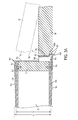
- Figs. 1 and 2 One known prior attempt to provide a door jamb which provides a flush finish with an in-swing door is seen in Figs. 1 and 2 .
- the door jamb 10 is cut from a block of wood and is affixed to the wall 12 via nail 14.
- the door jamb in cross section is configured to match the contour of the leading edge of the door 16.
- a smooth layer of plaster 18a is applied over the wall surface 12a and door jamb surface 10a.
- the jamb 10 includes a notch 10b (or an angled surface 10c in an alternate embodiment) which forms an enlarged open area 20a between the wall and jamb in which the plaster 18a may be applied and act as a further securing point for the plaster to hold to the wall and jamb. It is thus evident that this prior art door jamb does not provide the desired lasting visual results in that the plaster is incompatible with wood and is susceptible to crazing and cracking as indicated by reference numeral 22 in Fig. 1 .
- the securing nail or bolt
- the nail securement point which is located at the jamb-door interface
- the nail securement point which may cause the jamb to move relative to the wall stud and potentially cause intermittent and ultimately permanent separation of the jamb from the stud, the result of which creates unsightly jamb/wall gaps and cracking of the wall finish at this juncture.
- the present invention solves the above drawbacks of the prior art door jamb by providing a door jamb that is easy to install and gives the desired flush finish to an in-swing door while avoiding the prior art problems with cracking plaster and destructive jamb movement during use.
- the inventive door jamb comprises a unitary body having opposite side walls which are spaced a distance allowing the jamb to attach to a door opening with the side walls engaging opposite surfaces of the wall defining the door opening.
- the side walls include a plurality of holes through which suitable fasteners may be passed to secure the jamb to the wall stud defining the door opening.
- the jamb includes a plurality of wall segments which contiguously extend between the opposite side walls. The wall segments are formed into a desired geometry using a roll forming process, for example.
- a protrusion/juncture is formed in the jamb adjacent each of the opposite side walls and is spaced outwardly therefrom providing a space in which wall finishing material such as plaster may be applied over the jamb side wall (and extending through the holes in the side walls) up to the point of the protrusion/juncture.
- wall finishing material such as plaster
- the geometry of the jamb and corresponding complimentary geometry of the door leading latch face and door hinge face allow for the flush finish of the in-swing door front surface with the surrounding wall. More particularly, the jamb wall segments extending between the jamb side walls are sized and angled in a particular relationship with each other such that the in-swing (front) door surface will lie flush with the surrounding wall surface.
- the invention provides a door jamb for an in-swing door, said door jamb comprising:
- a unitary door jamb 30 which is made from a material which is compatible with other materials (e.g., plaster) which may be applied thereon as part of the installation and finishing process.
- Jamb 30 is preferably although not necessarily formed of a metal such as steel or aluminum, for example.
- door jamb 30 is formed into the desired geometry and provided in linear form which may be cut to the desired length.
- door jamb 30 is fabricated as a unitary part and formed into the desired geometry using a rolling process from a sheet of metal material.
- jamb 30 includes opposite first and second side walls 30a and 30b with seven defined wall segments 30b' 30c, 30d, 30e, 30ef, 30f, 30af extending contiguously therebetween, respectively.
- Side walls 30a and 30b are spaced from each other by a distance "D" which is slightly larger than the width "W" of the wall (including any dry wall such as indicated at 40a and 40b) to which it will be attached.
- the jamb side walls 30a and 30b engage and lie in abutting relation to the opposite sides of the wall stud (or to the sheets of any applied dry wall 40a, 40b) to which the jamb 30 attaches via suitable fasteners 50a, 50b which extend through selected ones of a plurality of jamb side wall holes 30a', 30b', respectively, and continue to extend through dry wall 40a,40b and into wall stud 12'.
- fasteners 50a, 50b extend toward each other (perpendicular to the plane of the door 16' when closed) from opposite ends of the wall stud 12'.
- the jamb 30 is thus very securely attached to the wall stud 12' and dry wall 40a, 40b.
- plaster 18a' and 18b' is applied over the jamb side walls 30a, 30b and flows through the side wall openings 30a', 30b', ultimately drying and "locking" the plaster to the jamb side walls.
- This structure between the jamb, fasteners, stud and plaster create an incredibly strong and stable jamb structure which all together could be considered a monolithic structure in terms of mechanical stability.
- jamb 30 can withstand forces of door movement without mechanically failing or separating from its surrounding structure as identified as a significant problem with the much less stable prior art in-swing door jambs discussed above.
- jamb 30 and corresponding complimentary geometry of the door leading latch face 16c' ( Figs. 3A and 6 ) and door hinge face 16d' ( Fig. 5 ) allow for the flush finish of the in-swing door front surface 16a' with wall 12a' ( Fig. 7 ). More particularly, the jamb wall segments extending between jamb first and second side walls 30a, 30b are sized and angled in a particular relationship with each other such that the in-swing (front) door surface 16a' will lie flush with the surrounding wall surface 12a'.
- jamb first side wall segment 30a extends to a third wall segment 30af which extends to protrusion/juncture "j" which extends to fourth wall segment 30f; fourth wall segment 30f extends to fifth wall segment 30ef; fifth wall segment 30ef extends to sixth wall segment 30e; sixth wall segment 30e extends to seventh wall segment 30d; seventh wall segment 30d extends to eighth wall segment 30c which itself extends substantially parallel to and spaced from wall segment 30e; and eighth wall segment 30c extends to ninth wall segment 30b' which extends back toward and joins second side wall 30b.
- the protrusion or juncture formed at the intersection of wall segments 30f and 30af is indicated by arrow "j" and is offset by a distance d 10 from the plane in which side wall segment 30a lies. It is within this space d 10 that finishing materials such as plaster 18a' ( Fig. 3A ) may be applied over wall segment 30a (and extending into substantially all of the holes 30a', 30b' (see Fig. 4 ) and blended with the remaining wall surface 40a such that the finishing surface 18a' creates an aesthetically pleasing, uninterrupted wall surface up to juncture "j". As seen in Fig. 3A , the plaster 18a' when applied may be gradually tapered down to the dry wall as the plaster extends in a direction opposite to the door opening.
- plaster 18a' when applied may be gradually tapered down to the dry wall as the plaster extends in a direction opposite to the door opening.
- the same process may be performed adjacent second side wall 30b where the distance between the outwardly facing surface of side wall 30b and protrusion 30bc forms a space d 11 where finishing material such as plaster 18b' may be applied over wall segment 30b and blended with the remaining wall surface 40b such that the finishing surface 18b' creates an aesthetically pleasing, uninterrupted wall surface up the protrusion 30bc.
- finishing material such as plaster 18b' may be applied over wall segment 30b and blended with the remaining wall surface 40b such that the finishing surface 18b' creates an aesthetically pleasing, uninterrupted wall surface up the protrusion 30bc.
- wall segment 30b' extends at an obtuse angle "a" relative to wall segment 30b and forms a protrusion indicated at 30bc.
- Wall segment 30c extends approximately perpendicular to wall segment 30b. In one embodiment, wall segment 30c extends at an angle of about 88 degrees relative to wall segment 30b.
- Wall segment 30d extends from wall segment 30c at a substantially right angle "b”.
- Wall segment 30e extends from wall segment 30d at a substantially right angle "c”.
- Wall segment 30ef extends from wall segment30e at an obtuse angle "d"
- wall segment 30f extends from wall segment 30ef at an obtuse angle "e”.
- wall segment 30a extends from wall segment 30af at an obtuse angle "g". In one embodiment, wall segment 30a extends at an angle of about 88 degrees relative to wall segment 30e. Of course the particular angles may vary to fit the jamb 30 to the particular door and door opening dimensions.
- wall segment 30b extends from its free end to wall segment 30b' by a distance d 9 ; wall segment 30b' extends at a distance d 1 ; wall segment 30c extends at a distance d 2 ; wall segment 30d extends a distance d 3 ; wall segment 30e extends between wall segment 30d and 30ef a distance d 4 ; wall segment 30ef extends between wall segments 30e and 30f by a distance d 5 ; wall segment 30f extends between wall segments 30ef and 30af by a distance d 6 ; wall segment 30af extends between wall segments 30a and 30f be a distance d 7 ; and wall segment 30a extends between its free end and wall segment 30af by a distance d 8 .
- d 1 is about .25
- d 2 is about 3.5
- d 3 is about .25
- d 4 is about 1.25
- d 5 is about .25
- d 6 is about .30
- d 7 is about .25
- d 8 is about 2"
- d 9 is about 1.25".
- these particular distances may vary to fit the jamb to the particular door and door opening dimensions.
- plaster 18a' is applied over dry wall 40a and jamb side wall 30a up to the point of protrusion/junction "j".
- plaster 18b' is applied over dry wall 40b and jamb side wall 30b up to the point of protrusion 30bc.
- the same door jamb 30 (with differently positioned openings for the door hinge hardware as will be discussed below) is used at the hinge edge of the door 16d' ( Fig. 5 ).
- the door latch face 16c' and door hinge face 16d' each include an angled profile which is complimentary to and thus closely matches the angled profile of fourth, fifth and sixth jamb wall segments 30f, 30ef and 30e, respectively.
- the door latch face front edge 16a" of door 16' will lie in a mating fashion closely adjacent to jamb protrusion "j" (see Figs. 3A , 6 (door is slightly ajar in Fig. 6 ) and 7 ), and the hinge face front edge 16" of door 16' will lie in a mating fashion closely adjacent jamb protrusion "j" (see Figs. 5 (door is slightly ajar in Fig. 5 ) and 7 ).
- openings may be formed in jamb 30 to accommodate hardware such as a door latch and hinges.
- openings 30e" are formed in jamb wall segment 30e to accommodate top and bottom concealed-type hinges 36. As such, when the door is closed, concealed hinges 36 are not visible. It is understood other types of hinges which may be visible may be used as desired.
- opening 30e"' is formed in jamb wall segment 30e to accommodate latch receiver 38b in which door latch 38a locates when the door is closed. Latch 38a is mechanically connected to door handle 38 and when the door is closed, latch receiver 38b and latch 38a are also visible.
Landscapes
- Engineering & Computer Science (AREA)
- Civil Engineering (AREA)
- Structural Engineering (AREA)
- Architecture (AREA)
- Mechanical Engineering (AREA)
- Wing Frames And Configurations (AREA)
- Hinges (AREA)
Abstract
Description
- The present invention generally relates to a door jamb and more particularly relates to a door jamb and door jamb assembly which allows for a flush finish of the door with respect to the adjoining wall on the side of the door facing the direction of door swing when opening.
- Conventional swing-type doors are mounted via hardware such as hinges to door jambs which attach to and define the opening in the wall at the location of the door. Doors and door jambs come in a variety of different materials and configurations depending on the desired functionality and aesthetics. A so-called "in-swing" door refers to a door which swings open into a space such as a room. If one were standing in a hallway of a hotel, for example, doors which swing open into the room (as opposed to swinging into the hallway) are referred to as "in-swing" doors. For many people, conventional door jambs for in-swing doors are visually displeasing in that they include multi-angled surfaces which are visible when the door is closed and thus fail to provide the complete "clean look" which is very desirable in present day architecture.
- One known prior attempt to provide a door jamb which provides a flush finish with an in-swing door is seen in
Figs. 1 and2 . In this prior art door jamb, thedoor jamb 10 is cut from a block of wood and is affixed to thewall 12 vianail 14. The door jamb in cross section is configured to match the contour of the leading edge of thedoor 16. In order to blend the wood door jamb with thewall surface 12a and also achieve the desired flush finish atdoor side 16a withwall side 12a, a smooth layer ofplaster 18a is applied over thewall surface 12a anddoor jamb surface 10a. In order to enhance the bonding of theplaster layer 18a to the wall and jamb, thejamb 10 includes anotch 10b (or anangled surface 10c in an alternate embodiment) which forms an enlargedopen area 20a between the wall and jamb in which theplaster 18a may be applied and act as a further securing point for the plaster to hold to the wall and jamb. It is thus evident that this prior art door jamb does not provide the desired lasting visual results in that the plaster is incompatible with wood and is susceptible to crazing and cracking as indicated byreference numeral 22 inFig. 1 . - Furthermore, and quite critically, the fact that the securing nail (or bolt) extends through the jamb in line with the direction of the wall (i.e., the nail extends generally parallel to the direction in which the wall extends) creates a weak attachment between the
jamb 10 and wall stud. More particularly, the forces created during regular door opening and closing at the jamb impact the nail securement point (which is located at the jamb-door interface) which may cause the jamb to move relative to the wall stud and potentially cause intermittent and ultimately permanent separation of the jamb from the stud, the result of which creates unsightly jamb/wall gaps and cracking of the wall finish at this juncture. This prior art door jamb (as well as any other prior art jambs which are secured with fasteners located at the door/jamb interface) is therefore not an appropriate solution to the need for a door jamb which provides a long-lasting flush finish for an in-swing door. - The present invention solves the above drawbacks of the prior art door jamb by providing a door jamb that is easy to install and gives the desired flush finish to an in-swing door while avoiding the prior art problems with cracking plaster and destructive jamb movement during use.
- In an embodiment, the inventive door jamb comprises a unitary body having opposite side walls which are spaced a distance allowing the jamb to attach to a door opening with the side walls engaging opposite surfaces of the wall defining the door opening. The side walls include a plurality of holes through which suitable fasteners may be passed to secure the jamb to the wall stud defining the door opening. The jamb includes a plurality of wall segments which contiguously extend between the opposite side walls. The wall segments are formed into a desired geometry using a roll forming process, for example. A protrusion/juncture is formed in the jamb adjacent each of the opposite side walls and is spaced outwardly therefrom providing a space in which wall finishing material such as plaster may be applied over the jamb side wall (and extending through the holes in the side walls) up to the point of the protrusion/juncture. The geometry of the jamb and corresponding complimentary geometry of the door leading latch face and door hinge face allow for the flush finish of the in-swing door front surface with the surrounding wall. More particularly, the jamb wall segments extending between the jamb side walls are sized and angled in a particular relationship with each other such that the in-swing (front) door surface will lie flush with the surrounding wall surface.
- In an embodiment, the invention provides a door jamb for an in-swing door, said door jamb comprising:
- first and second, spaced side wall segments adapted to be attached to opposite sides of a wall stud at a door opening;
- third, fourth, fifth and sixth contiguous wall segments extending from said first side wall toward said second side wall, said third and fourth wall segments forming a protrusion at their juncture, said protrusion and said first side wall being offset from each other and thereby defining a space which may be filled with a wall finishing material;
- said fourth wall segment extending parallel to and spaced from said sixth wall segment such that said fourth, fifth and sixth wall segments together form a stepped surface against which a complimentary shaped door latch face surface of an in-swing door is positioned when in the closed position and wherein the door latch face front edge lies closely adjacent said protrusion to create a flush finish of the door front surface with the wall surrounding the door opening.
- The above-mentioned and other features and advantages of this invention, and the manner of attaining them, will become apparent and be better understood by reference to the following description of the invention in conjunction with the accompanying drawing, wherein:
-
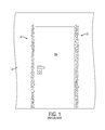
FIG. 1 is prior art a front elevational view of a flush in-swing door installed using a prior art door jamb; -
FIG. 2 is prior art showing a fragmented, enlarged cross-sectional view of the wall, door jamb and door ofFig. 1 ; -
FIG. 3A is a fragmented, enlarged, cross sectional view of an embodiment of the present invention showing the wall, door jamb and door leading edge; -
FIG 3B is a cross-sectional view of the door jamb with angle labels; -
FIG 3C is the view ofFIG. 3B , simplified, with dimension labels; -
FIG. 4 is a perspective view of the door jamb seen inFigs. 3A-C and5-7 ; -
FIG. 5 is a fragmented, perspective view of the wall and hinged edge of the door mounted to the inventive door jamb with the door shown slightly opened; -
FIG. 6 is a fragmented, perspective view of the wall with inventive door jamb located adjacent the leading edge of the door opposite the hinged edge of the door seen inFig. 5 ; and -
FIG. 7 is a front elevational view showing the adjoining walls and door ofFIGS. 3A ,5 and6 when in the closed position and viewed from the front (direction of swing when the door is opened). - This document provides and describes an overview of an exemplary environment and implementation of the present invention.
- Referring to
Figs. 3-6 , one possible embodiment of the invention is shown to include aunitary door jamb 30 which is made from a material which is compatible with other materials (e.g., plaster) which may be applied thereon as part of the installation and finishing process.Jamb 30 is preferably although not necessarily formed of a metal such as steel or aluminum, for example. During manufacture,door jamb 30 is formed into the desired geometry and provided in linear form which may be cut to the desired length. In one embodiment,door jamb 30 is fabricated as a unitary part and formed into the desired geometry using a rolling process from a sheet of metal material. - As seen best in
Figs. 3A-C and4 ,jamb 30 includes opposite first andsecond side walls wall 30c, 30d, 30e, 30ef, 30f, 30af extending contiguously therebetween, respectively.segments 30b'Side walls jamb 30 is mounted to the wall stud 12', thejamb side walls dry wall jamb 30 attaches viasuitable fasteners side wall holes 30a', 30b', respectively, and continue to extend throughdry wall - As seen in
Fig. 3A ,fasteners jamb 30 is thus very securely attached to the wall stud 12' anddry wall plaster 18a' and 18b' is applied over thejamb side walls side wall openings 30a', 30b', ultimately drying and "locking" the plaster to the jamb side walls. This structure between the jamb, fasteners, stud and plaster create an incredibly strong and stable jamb structure which all together could be considered a monolithic structure in terms of mechanical stability. As such,jamb 30 can withstand forces of door movement without mechanically failing or separating from its surrounding structure as identified as a significant problem with the much less stable prior art in-swing door jambs discussed above. - The geometry of
jamb 30 and corresponding complimentary geometry of the door leadinglatch face 16c' (Figs. 3A and6 ) anddoor hinge face 16d' (Fig. 5 ) allow for the flush finish of the in-swing doorfront surface 16a' withwall 12a' (Fig. 7 ). More particularly, the jamb wall segments extending between jamb first andsecond side walls door surface 16a' will lie flush with the surroundingwall surface 12a'. - As seen best in the embodiment of
Figs. 3A-C , jamb firstside wall segment 30a extends to a third wall segment 30af which extends to protrusion/juncture "j" which extends tofourth wall segment 30f;fourth wall segment 30f extends to fifth wall segment 30ef; fifth wall segment 30ef extends tosixth wall segment 30e;sixth wall segment 30e extends toseventh wall segment 30d;seventh wall segment 30d extends toeighth wall segment 30c which itself extends substantially parallel to and spaced fromwall segment 30e; andeighth wall segment 30c extends toninth wall segment 30b' which extends back toward and joinssecond side wall 30b. - The protrusion or juncture formed at the intersection of
wall segments 30f and 30af is indicated by arrow "j" and is offset by a distance d10 from the plane in whichside wall segment 30a lies. It is within this space d10 that finishing materials such asplaster 18a' (Fig. 3A ) may be applied overwall segment 30a (and extending into substantially all of theholes 30a', 30b' (seeFig. 4 ) and blended with the remainingwall surface 40a such that the finishingsurface 18a' creates an aesthetically pleasing, uninterrupted wall surface up to juncture "j". As seen inFig. 3A , theplaster 18a' when applied may be gradually tapered down to the dry wall as the plaster extends in a direction opposite to the door opening. - The same process may be performed adjacent
second side wall 30b where the distance between the outwardly facing surface ofside wall 30b and protrusion 30bc forms a space d11 where finishing material such asplaster 18b' may be applied overwall segment 30b and blended with the remainingwall surface 40b such that the finishingsurface 18b' creates an aesthetically pleasing, uninterrupted wall surface up the protrusion 30bc. - As explained above, the individual wall segments are angled with respect to each other in a manner allowing the
jamb 30 to create the desired flush in-swing door. In the embodiment ofFIG. 3B ,wall segment 30b' extends at an obtuse angle "a" relative towall segment 30b and forms a protrusion indicated at 30bc.Wall segment 30c extends approximately perpendicular towall segment 30b. In one embodiment,wall segment 30c extends at an angle of about 88 degrees relative towall segment 30b.Wall segment 30d extends fromwall segment 30c at a substantially right angle "b".Wall segment 30e extends fromwall segment 30d at a substantially right angle "c". Wall segment 30ef extends from wall segment30e at an obtuse angle "d", andwall segment 30f extends from wall segment 30ef at an obtuse angle "e". - The juncture of
wall segments 30f and 30af forms a protrusion or juncture "j" having an acute inner angle "f".Wall segment 30a extends from wall segment 30af at an obtuse angle "g". In one embodiment,wall segment 30a extends at an angle of about 88 degrees relative towall segment 30e. Of course the particular angles may vary to fit thejamb 30 to the particular door and door opening dimensions. - Referring to
Fig. 3C ,wall segment 30b extends from its free end towall segment 30b' by a distance d9;wall segment 30b' extends at a distance d1;wall segment 30c extends at a distance d2;wall segment 30d extends a distance d3;wall segment 30e extends betweenwall segment 30d and 30ef a distance d4; wall segment 30ef extends betweenwall segments wall segment 30f extends between wall segments 30ef and 30af by a distance d6; wall segment 30af extends betweenwall segments wall segment 30a extends between its free end and wall segment 30af by a distance d8. - In one embodiment, d1 is about .25", d2 is about 3.5", d3 is about .25", d4 is about 1.25", d5 is about .25", d6 is about .30", d7 is about .25", d8 is about 2" and d9 is about 1.25". Of course these particular distances may vary to fit the jamb to the particular door and door opening dimensions.
- As seen in
Fig. 3A and as explained above,plaster 18a' is applied overdry wall 40a andjamb side wall 30a up to the point of protrusion/junction "j". Likewise, on the other side,plaster 18b' is applied overdry wall 40b andjamb side wall 30b up to the point of protrusion 30bc. - The same door jamb 30 (with differently positioned openings for the door hinge hardware as will be discussed below) is used at the hinge edge of the
door 16d' (Fig. 5 ). - The
door latch face 16c' anddoor hinge face 16d' each include an angled profile which is complimentary to and thus closely matches the angled profile of fourth, fifth and sixthjamb wall segments 30f, 30ef and 30e, respectively. When in the closed position, the door latch facefront edge 16a" of door 16' will lie in a mating fashion closely adjacent to jamb protrusion "j" (seeFigs. 3A ,6 (door is slightly ajar inFig. 6 ) and7 ), and the hinge facefront edge 16" of door 16' will lie in a mating fashion closely adjacent jamb protrusion "j" (seeFigs. 5 (door is slightly ajar inFig. 5 ) and7 ). - Thus, as seen best in
Figs. 3A and7 , when in the closed position, as looking at thefront surface 16a' of the in-swing door (toward the direction of in-swing), the doorfront surface 16a' will lie flush with the surrounding wall with the only part of each jamb 30 (one along the latch side and one along the hinge side of the door) showing being the extremely narrow width juncture segment "j". - As mentioned above, openings may be formed in
jamb 30 to accommodate hardware such as a door latch and hinges. InFig. 5 ,openings 30e" are formed injamb wall segment 30e to accommodate top and bottom concealed-type hinges 36. As such, when the door is closed, concealed hinges 36 are not visible. It is understood other types of hinges which may be visible may be used as desired. InFig. 6 , opening 30e"' is formed injamb wall segment 30e to accommodatelatch receiver 38b in whichdoor latch 38a locates when the door is closed.Latch 38a is mechanically connected todoor handle 38 and when the door is closed,latch receiver 38b andlatch 38a are also visible. - While the invention has been shown and described with reference to certain preferred embodiments thereof, it will be understood by those skilled in the art that various changes in form and details may be made therein without departing from the spirit and scope of the invention as described.
Claims (6)
- A door jamb for an in-swing door, said door jamb comprising:a) first and second, spaced side wall segments adapted to be attached to opposite sides of a wall stud at a door opening;b) third, fourth, fifth and sixth contiguous wall segments extending from said first side wall toward said second side wall, said third and fourth wall segments forming a protrusion at their juncture, said protrusion and said first side wall being offset from each other and thereby defining a space (d10) which may be filled with a wall finishing material;c) said fourth wall segment extending parallel to and spaced from said sixth wall segment such that said fourth, fifth and sixth wall segments together form a stepped surface against which a complimentary shaped door latch face surface of an in-swing door is positioned when in the closed position and wherein the door latch face front edge lies closely adjacent said protrusion to create a flush finish of the door front surface with the wall surrounding the door opening.
- The door jamb of claim 1, and further comprising a second door jamb for locating adjacent the hinge face of an in-swing door, and wherein the hinge face is complimentary shaped to said fourth, fifth and sixth wall segments of said second door jamb and wherein the hinge face front edge lies closely adjacent said second door jamb protrusion to create a flush finish of the door front surface with the wall surrounding the door opening.
- The door jamb of claim 1 or claim 2, and further comprising seventh, eighth and ninth wall segments extending contiguously between said second side wall segment and said sixth wall segment, said eighth wall segment extending spaced and parallel to said sixth wall segment, the juncture of said eighth and ninth segments forming a second protrusion, said second protrusion and said second side wall being offset from each other and thereby defining a space (d11) which may be filled with a wall finishing material.
- The door jamb of claim 1, claim 2 or claim 3, wherein said first and second side walls each include a plurality of openings through which fasteners and wall finishing material may extend.
- A unitary door jamb for an in-swing door, said jamb adapted to be secured to a wall stud defining a door opening wherein the in-swing door is mounted, said jamb comprising:a) first and second opposite side walls adapted to engage opposite sides of the wall stud, with a plurality of wall segments extending contiguously between said opposite first and second side walls, said plurality of wall segments defining a stepped surface which mates with a complimentary stepped surface of the in-swing door when the door is closed, the mating stepped surfaces configured to create a flush finish between the door and the wall surrounding the door opening when the door is closed.
- The door jamb of claim 5 wherein said first and second opposite side walls each include a plurality of openings through which fasteners and wall finishing material may extend with the fasteners extending in a direction substantially perpendicular to the plane of the door.
Applications Claiming Priority (1)
| Application Number | Priority Date | Filing Date | Title |
|---|---|---|---|
| US201361882836P | 2013-09-26 | 2013-09-26 |
Publications (2)
| Publication Number | Publication Date |
|---|---|
| EP2857622A1 true EP2857622A1 (en) | 2015-04-08 |
| EP2857622B1 EP2857622B1 (en) | 2020-09-23 |
Family
ID=51625884
Family Applications (1)
| Application Number | Title | Priority Date | Filing Date |
|---|---|---|---|
| EP14186556.8A Active EP2857622B1 (en) | 2013-09-26 | 2014-09-26 | Door jamb for flush in-swing door |
Country Status (5)
| Country | Link |
|---|---|
| US (2) | US9416580B2 (en) |
| EP (1) | EP2857622B1 (en) |
| AU (1) | AU2014233627B2 (en) |
| CA (1) | CA2866036C (en) |
| ES (1) | ES2826990T3 (en) |
Cited By (1)
| Publication number | Priority date | Publication date | Assignee | Title |
|---|---|---|---|---|
| GB2552767A (en) * | 2016-06-07 | 2018-02-14 | Linear Building Innovations Ltd | Automatic opening vent |
Families Citing this family (7)
| Publication number | Priority date | Publication date | Assignee | Title |
|---|---|---|---|---|
| CA2892839C (en) * | 2014-10-30 | 2016-02-23 | Maxam Metal Products Limited | Insert access door |
| US10087674B2 (en) | 2015-10-21 | 2018-10-02 | Industries Dorr Inc. | Concealable flush wall door structural frame and flush wall door assembly including same |
| USD839454S1 (en) * | 2017-04-24 | 2019-01-29 | Robert ZIEGAN | Grid edging |
| US10407840B2 (en) | 2017-05-16 | 2019-09-10 | Robert ZIEGAN | Surface system and method of installation |
| FR3091717B1 (en) * | 2019-01-11 | 2021-01-29 | Imaform | Door covering structure |
| AU2020102698A4 (en) * | 2020-10-13 | 2020-12-03 | Studco Australia Pty Ltd | Internal wall end apparatus |
| GB2631910B (en) * | 2022-10-31 | 2025-07-16 | Linear Building Innovations Ltd | Installation system for a doorset and a method of use thereof |
Citations (2)
| Publication number | Priority date | Publication date | Assignee | Title |
|---|---|---|---|---|
| WO1997042390A1 (en) * | 1996-05-06 | 1997-11-13 | Ross James Beaton | Door frames |
| AT506226A4 (en) * | 2008-04-08 | 2009-07-15 | Robert Nussbaum | MULTIFUNKTIONSZARGE |
Family Cites Families (14)
| Publication number | Priority date | Publication date | Assignee | Title |
|---|---|---|---|---|
| US1015989A (en) * | 1911-05-31 | 1912-01-30 | Faconeisenwalzwerk L Mannstaedt & Cie Act Ges | Door-frame. |
| NL8200848A (en) * | 1982-03-03 | 1983-10-03 | Polynorm Nv | DEVICE FOR MOUNTING A METAL STYLE OR FRAME IN A WALL OPENING, IN PARTICULAR A DOOR STYLE. |
| EP0303334B1 (en) | 1983-10-13 | 1991-05-29 | Polynorm N.V. | Frame for door or window opening |
| US4665666A (en) * | 1984-12-04 | 1987-05-19 | Hampton Wade J | Prefabricated archway |
| US4698944A (en) | 1986-10-20 | 1987-10-13 | Wilkins Jr William R | Flush finishing metal door frame |
| US5630302A (en) * | 1996-02-02 | 1997-05-20 | Morgan Marshall Industries, Inc. | Fitting room |
| IES970802A2 (en) * | 1997-06-27 | 1998-12-30 | Perbrisu Limited | Two portion frame |
| US6550193B2 (en) | 2001-09-07 | 2003-04-22 | Thomas Lee Potts | Split jamb for doors and windows |
| US7516581B2 (en) | 2005-05-12 | 2009-04-14 | Rolando Vidal | Split door frame assembly |
| GB2443092A (en) * | 2006-10-20 | 2008-04-23 | Studco Building Systems Pty Lt | Clip for door or window frame |
| WO2009006540A2 (en) * | 2007-07-05 | 2009-01-08 | The Mills Company Inc. | Partition system |
| US20100230979A1 (en) * | 2009-03-16 | 2010-09-16 | Gries Ulysses E | Doorway Having a Recessed Magnetic Lock |
| GB201003816D0 (en) | 2010-03-08 | 2010-04-21 | Cooke Brothers Ltd | Improvements in or relating to door assemblies |
| FI20106199A0 (en) | 2010-11-15 | 2010-11-15 | Inlook Colortech Oy | Inspection hatch and inspection hatch frame |
-
2014
- 2014-09-26 US US14/498,125 patent/US9416580B2/en active Active
- 2014-09-26 CA CA2866036A patent/CA2866036C/en active Active
- 2014-09-26 AU AU2014233627A patent/AU2014233627B2/en active Active
- 2014-09-26 ES ES14186556T patent/ES2826990T3/en active Active
- 2014-09-26 EP EP14186556.8A patent/EP2857622B1/en active Active
-
2016
- 2016-07-12 US US15/207,922 patent/US9995080B2/en active Active
Patent Citations (2)
| Publication number | Priority date | Publication date | Assignee | Title |
|---|---|---|---|---|
| WO1997042390A1 (en) * | 1996-05-06 | 1997-11-13 | Ross James Beaton | Door frames |
| AT506226A4 (en) * | 2008-04-08 | 2009-07-15 | Robert Nussbaum | MULTIFUNKTIONSZARGE |
Cited By (2)
| Publication number | Priority date | Publication date | Assignee | Title |
|---|---|---|---|---|
| GB2552767A (en) * | 2016-06-07 | 2018-02-14 | Linear Building Innovations Ltd | Automatic opening vent |
| GB2552767B (en) * | 2016-06-07 | 2021-09-08 | Linear Building Innovations Ltd | Automatic opening vent |
Also Published As
| Publication number | Publication date |
|---|---|
| AU2014233627A1 (en) | 2015-04-09 |
| US20160319584A1 (en) | 2016-11-03 |
| EP2857622B1 (en) | 2020-09-23 |
| AU2014233627B2 (en) | 2018-04-19 |
| US20150082717A1 (en) | 2015-03-26 |
| US9995080B2 (en) | 2018-06-12 |
| ES2826990T3 (en) | 2021-05-19 |
| CA2866036C (en) | 2020-09-15 |
| CA2866036A1 (en) | 2015-03-26 |
| US9416580B2 (en) | 2016-08-16 |
Similar Documents
| Publication | Publication Date | Title |
|---|---|---|
| EP2857622B1 (en) | Door jamb for flush in-swing door | |
| AU2020100245A4 (en) | Improvements in snap fit posts for fence panels balustrades and the like | |
| US8627610B1 (en) | Privacy enclosure | |
| CA3078052C (en) | Fenestration trim assembly | |
| US20170058593A1 (en) | Versatile hybrid window system | |
| US20090007504A1 (en) | Partition system | |
| US20100122502A1 (en) | System and method for adjustable repair and reinforcement of non-standard doors and jambs | |
| US9080373B2 (en) | Jamb system | |
| EP3149264B1 (en) | Support frame for sliding door systems | |
| US7472519B2 (en) | Door jamb | |
| EP2990580A1 (en) | Break-in protection | |
| WO2007076569A1 (en) | An adjustable in-wall cavity sliding door frame assembly | |
| AU2020100633A4 (en) | Mount assembly for door jambs | |
| AU2017204156B2 (en) | Door jamb assembly | |
| CA2548612C (en) | Door jamb | |
| NZ735259B2 (en) | Improvements in snap fit posts for fence panels balustrades and the like |
Legal Events
| Date | Code | Title | Description |
|---|---|---|---|
| PUAI | Public reference made under article 153(3) epc to a published international application that has entered the european phase |
Free format text: ORIGINAL CODE: 0009012 |
|
| 17P | Request for examination filed |
Effective date: 20140926 |
|
| AK | Designated contracting states |
Kind code of ref document: A1 Designated state(s): AL AT BE BG CH CY CZ DE DK EE ES FI FR GB GR HR HU IE IS IT LI LT LU LV MC MK MT NL NO PL PT RO RS SE SI SK SM TR |
|
| AX | Request for extension of the european patent |
Extension state: BA ME |
|
| R17P | Request for examination filed (corrected) |
Effective date: 20150924 |
|
| RBV | Designated contracting states (corrected) |
Designated state(s): AL AT BE BG CH CY CZ DE DK EE ES FI FR GB GR HR HU IE IS IT LI LT LU LV MC MK MT NL NO PL PT RO RS SE SI SK SM TR |
|
| STAA | Information on the status of an ep patent application or granted ep patent |
Free format text: STATUS: EXAMINATION IS IN PROGRESS |
|
| 17Q | First examination report despatched |
Effective date: 20170224 |
|
| GRAP | Despatch of communication of intention to grant a patent |
Free format text: ORIGINAL CODE: EPIDOSNIGR1 |
|
| STAA | Information on the status of an ep patent application or granted ep patent |
Free format text: STATUS: GRANT OF PATENT IS INTENDED |
|
| INTG | Intention to grant announced |
Effective date: 20200415 |
|
| GRAS | Grant fee paid |
Free format text: ORIGINAL CODE: EPIDOSNIGR3 |
|
| GRAA | (expected) grant |
Free format text: ORIGINAL CODE: 0009210 |
|
| STAA | Information on the status of an ep patent application or granted ep patent |
Free format text: STATUS: THE PATENT HAS BEEN GRANTED |
|
| AK | Designated contracting states |
Kind code of ref document: B1 Designated state(s): AL AT BE BG CH CY CZ DE DK EE ES FI FR GB GR HR HU IE IS IT LI LT LU LV MC MK MT NL NO PL PT RO RS SE SI SK SM TR |
|
| REG | Reference to a national code |
Ref country code: GB Ref legal event code: FG4D |
|
| REG | Reference to a national code |
Ref country code: CH Ref legal event code: EP |
|
| REG | Reference to a national code |
Ref country code: IE Ref legal event code: FG4D |
|
| REG | Reference to a national code |
Ref country code: DE Ref legal event code: R096 Ref document number: 602014070424 Country of ref document: DE Ref country code: AT Ref legal event code: REF Ref document number: 1316536 Country of ref document: AT Kind code of ref document: T Effective date: 20201015 |
|
| REG | Reference to a national code |
Ref country code: NL Ref legal event code: FP |
|
| PG25 | Lapsed in a contracting state [announced via postgrant information from national office to epo] |
Ref country code: HR Free format text: LAPSE BECAUSE OF FAILURE TO SUBMIT A TRANSLATION OF THE DESCRIPTION OR TO PAY THE FEE WITHIN THE PRESCRIBED TIME-LIMIT Effective date: 20200923 Ref country code: NO Free format text: LAPSE BECAUSE OF FAILURE TO SUBMIT A TRANSLATION OF THE DESCRIPTION OR TO PAY THE FEE WITHIN THE PRESCRIBED TIME-LIMIT Effective date: 20201223 Ref country code: BG Free format text: LAPSE BECAUSE OF FAILURE TO SUBMIT A TRANSLATION OF THE DESCRIPTION OR TO PAY THE FEE WITHIN THE PRESCRIBED TIME-LIMIT Effective date: 20201223 Ref country code: FI Free format text: LAPSE BECAUSE OF FAILURE TO SUBMIT A TRANSLATION OF THE DESCRIPTION OR TO PAY THE FEE WITHIN THE PRESCRIBED TIME-LIMIT Effective date: 20200923 Ref country code: GR Free format text: LAPSE BECAUSE OF FAILURE TO SUBMIT A TRANSLATION OF THE DESCRIPTION OR TO PAY THE FEE WITHIN THE PRESCRIBED TIME-LIMIT Effective date: 20201224 Ref country code: SE Free format text: LAPSE BECAUSE OF FAILURE TO SUBMIT A TRANSLATION OF THE DESCRIPTION OR TO PAY THE FEE WITHIN THE PRESCRIBED TIME-LIMIT Effective date: 20200923 |
|
| REG | Reference to a national code |
Ref country code: AT Ref legal event code: MK05 Ref document number: 1316536 Country of ref document: AT Kind code of ref document: T Effective date: 20200923 |
|
| PG25 | Lapsed in a contracting state [announced via postgrant information from national office to epo] |
Ref country code: LV Free format text: LAPSE BECAUSE OF FAILURE TO SUBMIT A TRANSLATION OF THE DESCRIPTION OR TO PAY THE FEE WITHIN THE PRESCRIBED TIME-LIMIT Effective date: 20200923 Ref country code: RS Free format text: LAPSE BECAUSE OF FAILURE TO SUBMIT A TRANSLATION OF THE DESCRIPTION OR TO PAY THE FEE WITHIN THE PRESCRIBED TIME-LIMIT Effective date: 20200923 |
|
| REG | Reference to a national code |
Ref country code: LT Ref legal event code: MG4D |
|
| PG25 | Lapsed in a contracting state [announced via postgrant information from national office to epo] |
Ref country code: LT Free format text: LAPSE BECAUSE OF FAILURE TO SUBMIT A TRANSLATION OF THE DESCRIPTION OR TO PAY THE FEE WITHIN THE PRESCRIBED TIME-LIMIT Effective date: 20200923 Ref country code: PT Free format text: LAPSE BECAUSE OF FAILURE TO SUBMIT A TRANSLATION OF THE DESCRIPTION OR TO PAY THE FEE WITHIN THE PRESCRIBED TIME-LIMIT Effective date: 20210125 Ref country code: RO Free format text: LAPSE BECAUSE OF FAILURE TO SUBMIT A TRANSLATION OF THE DESCRIPTION OR TO PAY THE FEE WITHIN THE PRESCRIBED TIME-LIMIT Effective date: 20200923 Ref country code: SM Free format text: LAPSE BECAUSE OF FAILURE TO SUBMIT A TRANSLATION OF THE DESCRIPTION OR TO PAY THE FEE WITHIN THE PRESCRIBED TIME-LIMIT Effective date: 20200923 Ref country code: CZ Free format text: LAPSE BECAUSE OF FAILURE TO SUBMIT A TRANSLATION OF THE DESCRIPTION OR TO PAY THE FEE WITHIN THE PRESCRIBED TIME-LIMIT Effective date: 20200923 Ref country code: EE Free format text: LAPSE BECAUSE OF FAILURE TO SUBMIT A TRANSLATION OF THE DESCRIPTION OR TO PAY THE FEE WITHIN THE PRESCRIBED TIME-LIMIT Effective date: 20200923 |
|
| REG | Reference to a national code |
Ref country code: CH Ref legal event code: PL |
|
| REG | Reference to a national code |
Ref country code: ES Ref legal event code: FG2A Ref document number: 2826990 Country of ref document: ES Kind code of ref document: T3 Effective date: 20210519 |
|
| PG25 | Lapsed in a contracting state [announced via postgrant information from national office to epo] |
Ref country code: AT Free format text: LAPSE BECAUSE OF FAILURE TO SUBMIT A TRANSLATION OF THE DESCRIPTION OR TO PAY THE FEE WITHIN THE PRESCRIBED TIME-LIMIT Effective date: 20200923 Ref country code: AL Free format text: LAPSE BECAUSE OF FAILURE TO SUBMIT A TRANSLATION OF THE DESCRIPTION OR TO PAY THE FEE WITHIN THE PRESCRIBED TIME-LIMIT Effective date: 20200923 Ref country code: IS Free format text: LAPSE BECAUSE OF FAILURE TO SUBMIT A TRANSLATION OF THE DESCRIPTION OR TO PAY THE FEE WITHIN THE PRESCRIBED TIME-LIMIT Effective date: 20210123 Ref country code: PL Free format text: LAPSE BECAUSE OF FAILURE TO SUBMIT A TRANSLATION OF THE DESCRIPTION OR TO PAY THE FEE WITHIN THE PRESCRIBED TIME-LIMIT Effective date: 20200923 |
|
| REG | Reference to a national code |
Ref country code: DE Ref legal event code: R097 Ref document number: 602014070424 Country of ref document: DE |
|
| PG25 | Lapsed in a contracting state [announced via postgrant information from national office to epo] |
Ref country code: SK Free format text: LAPSE BECAUSE OF FAILURE TO SUBMIT A TRANSLATION OF THE DESCRIPTION OR TO PAY THE FEE WITHIN THE PRESCRIBED TIME-LIMIT Effective date: 20200923 Ref country code: MC Free format text: LAPSE BECAUSE OF FAILURE TO SUBMIT A TRANSLATION OF THE DESCRIPTION OR TO PAY THE FEE WITHIN THE PRESCRIBED TIME-LIMIT Effective date: 20200923 |
|
| PLBE | No opposition filed within time limit |
Free format text: ORIGINAL CODE: 0009261 |
|
| STAA | Information on the status of an ep patent application or granted ep patent |
Free format text: STATUS: NO OPPOSITION FILED WITHIN TIME LIMIT |
|
| PG25 | Lapsed in a contracting state [announced via postgrant information from national office to epo] |
Ref country code: SI Free format text: LAPSE BECAUSE OF FAILURE TO SUBMIT A TRANSLATION OF THE DESCRIPTION OR TO PAY THE FEE WITHIN THE PRESCRIBED TIME-LIMIT Effective date: 20200923 Ref country code: LI Free format text: LAPSE BECAUSE OF NON-PAYMENT OF DUE FEES Effective date: 20200930 Ref country code: CH Free format text: LAPSE BECAUSE OF NON-PAYMENT OF DUE FEES Effective date: 20200930 Ref country code: DK Free format text: LAPSE BECAUSE OF FAILURE TO SUBMIT A TRANSLATION OF THE DESCRIPTION OR TO PAY THE FEE WITHIN THE PRESCRIBED TIME-LIMIT Effective date: 20200923 |
|
| 26N | No opposition filed |
Effective date: 20210624 |
|
| PG25 | Lapsed in a contracting state [announced via postgrant information from national office to epo] |
Ref country code: IT Free format text: LAPSE BECAUSE OF FAILURE TO SUBMIT A TRANSLATION OF THE DESCRIPTION OR TO PAY THE FEE WITHIN THE PRESCRIBED TIME-LIMIT Effective date: 20200923 |
|
| PG25 | Lapsed in a contracting state [announced via postgrant information from national office to epo] |
Ref country code: TR Free format text: LAPSE BECAUSE OF FAILURE TO SUBMIT A TRANSLATION OF THE DESCRIPTION OR TO PAY THE FEE WITHIN THE PRESCRIBED TIME-LIMIT Effective date: 20200923 Ref country code: MT Free format text: LAPSE BECAUSE OF FAILURE TO SUBMIT A TRANSLATION OF THE DESCRIPTION OR TO PAY THE FEE WITHIN THE PRESCRIBED TIME-LIMIT Effective date: 20200923 Ref country code: CY Free format text: LAPSE BECAUSE OF FAILURE TO SUBMIT A TRANSLATION OF THE DESCRIPTION OR TO PAY THE FEE WITHIN THE PRESCRIBED TIME-LIMIT Effective date: 20200923 |
|
| PG25 | Lapsed in a contracting state [announced via postgrant information from national office to epo] |
Ref country code: MK Free format text: LAPSE BECAUSE OF FAILURE TO SUBMIT A TRANSLATION OF THE DESCRIPTION OR TO PAY THE FEE WITHIN THE PRESCRIBED TIME-LIMIT Effective date: 20200923 |
|
| REG | Reference to a national code |
Ref country code: DE Ref legal event code: R081 Ref document number: 602014070424 Country of ref document: DE Owner name: SBS BUILDING SYSTEMS LTD., RUGBY, GB Free format text: FORMER OWNER: STUDCO BUILDING SYSTEMS US, LLC, WEBSTER, NY, US Ref country code: DE Ref legal event code: R082 Ref document number: 602014070424 Country of ref document: DE Representative=s name: DR. WEITZEL & PARTNER PATENT- UND RECHTSANWAEL, DE Ref country code: DE Ref legal event code: R081 Ref document number: 602014070424 Country of ref document: DE Owner name: STUDCO BUILDING SYSTEMS UK LTD, RUGBY, GB Free format text: FORMER OWNER: STUDCO BUILDING SYSTEMS US, LLC, WEBSTER, NY, US |
|
| REG | Reference to a national code |
Ref country code: LU Ref legal event code: PD Owner name: STUDCO BUILDING SYSTEMS UK LTD; GB Free format text: FORMER OWNER: STUDCO BUILDING SYSTEMS US, LLC Effective date: 20240412 |
|
| REG | Reference to a national code |
Ref country code: GB Ref legal event code: 732E Free format text: REGISTERED BETWEEN 20240411 AND 20240417 |
|
| REG | Reference to a national code |
Ref country code: NL Ref legal event code: PD Owner name: STUDCO BUILDING SYSTEMS UK LTD; GB Free format text: DETAILS ASSIGNMENT: CHANGE OF OWNER(S), ASSIGNMENT; FORMER OWNER NAME: STUDCO BUILDING SYSTEMS US, LLC Effective date: 20240702 |
|
| REG | Reference to a national code |
Ref country code: BE Ref legal event code: PD Owner name: STUDCO BUILDING SYSTEMS UK LTD.; GB Free format text: DETAILS ASSIGNMENT: CHANGE OF OWNER(S), ASSIGNMENT; FORMER OWNER NAME: STUDCO BUILDING SYSTEMS US, LLC Effective date: 20240605 |
|
| REG | Reference to a national code |
Ref country code: ES Ref legal event code: PC2A Owner name: STUDCO BUILDING SYSTEMS UK LTD Effective date: 20241023 |
|
| REG | Reference to a national code |
Ref country code: LU Ref legal event code: HC Owner name: SBS BUILDING SYSTEMS LTD.; GB Free format text: FORMER OWNER: STUDCO BUILDING SYSTEMS UK LTD Effective date: 20241224 |
|
| REG | Reference to a national code |
Ref country code: DE Ref legal event code: R081 Ref document number: 602014070424 Country of ref document: DE Owner name: SBS BUILDING SYSTEMS LTD., RUGBY, GB Free format text: FORMER OWNER: STUDCO BUILDING SYSTEMS UK LTD, RUGBY, WARWICKSHIRE, GB |
|
| REG | Reference to a national code |
Ref country code: NL Ref legal event code: HC Owner name: SBS BUILDING SYSTEMS LTD; GB Free format text: DETAILS ASSIGNMENT: CHANGE OF OWNER(S), CHANGE OF OWNER(S) NAME; FORMER OWNER NAME: STUDCO BUILDING SYSTEMS UK LTD Effective date: 20241220 |
|
| REG | Reference to a national code |
Ref country code: BE Ref legal event code: HC Owner name: SBS BUILDING SYSTEMS LTD; GB Free format text: DETAILS ASSIGNMENT: CHANGE OF OWNER(S), CHANGE OF OWNER(S) NAME; FORMER OWNER NAME: STUDCO BUILDING SYSTEMS UK LTD. Effective date: 20241231 |
|
| PGFP | Annual fee paid to national office [announced via postgrant information from national office to epo] |
Ref country code: DE Payment date: 20250925 Year of fee payment: 12 |
|
| PGFP | Annual fee paid to national office [announced via postgrant information from national office to epo] |
Ref country code: LU Payment date: 20250929 Year of fee payment: 12 Ref country code: NL Payment date: 20250924 Year of fee payment: 12 |
|
| PGFP | Annual fee paid to national office [announced via postgrant information from national office to epo] |
Ref country code: GB Payment date: 20250924 Year of fee payment: 12 Ref country code: BE Payment date: 20250924 Year of fee payment: 12 |
|
| PGFP | Annual fee paid to national office [announced via postgrant information from national office to epo] |
Ref country code: FR Payment date: 20250929 Year of fee payment: 12 |
|
| PGFP | Annual fee paid to national office [announced via postgrant information from national office to epo] |
Ref country code: IE Payment date: 20250924 Year of fee payment: 12 |
|
| REG | Reference to a national code |
Ref country code: ES Ref legal event code: PC2A Owner name: SBS BUILDING SYSTEMS LTD Effective date: 20251119 |
|
| PGFP | Annual fee paid to national office [announced via postgrant information from national office to epo] |
Ref country code: ES Payment date: 20251001 Year of fee payment: 12 |