EP2857347A1 - Optical deflecting mirror device having figure "8"-shaped rib and optical deflector - Google Patents
Optical deflecting mirror device having figure "8"-shaped rib and optical deflector Download PDFInfo
- Publication number
- EP2857347A1 EP2857347A1 EP14183759.1A EP14183759A EP2857347A1 EP 2857347 A1 EP2857347 A1 EP 2857347A1 EP 14183759 A EP14183759 A EP 14183759A EP 2857347 A1 EP2857347 A1 EP 2857347A1
- Authority
- EP
- European Patent Office
- Prior art keywords
- mirror device
- optical
- deflecting mirror
- optical deflecting
- shaped reinforcement
- Prior art date
- Legal status (The legal status is an assumption and is not a legal conclusion. Google has not performed a legal analysis and makes no representation as to the accuracy of the status listed.)
- Granted
Links
Images




Classifications
-
- G—PHYSICS
- G02—OPTICS
- G02B—OPTICAL ELEMENTS, SYSTEMS OR APPARATUS
- G02B26/00—Optical devices or arrangements for the control of light using movable or deformable optical elements
- G02B26/08—Optical devices or arrangements for the control of light using movable or deformable optical elements for controlling the direction of light
- G02B26/0816—Optical devices or arrangements for the control of light using movable or deformable optical elements for controlling the direction of light by means of one or more reflecting elements
- G02B26/0833—Optical devices or arrangements for the control of light using movable or deformable optical elements for controlling the direction of light by means of one or more reflecting elements the reflecting element being a micromechanical device, e.g. a MEMS mirror, DMD
-
- B—PERFORMING OPERATIONS; TRANSPORTING
- B81—MICROSTRUCTURAL TECHNOLOGY
- B81B—MICROSTRUCTURAL DEVICES OR SYSTEMS, e.g. MICROMECHANICAL DEVICES
- B81B3/00—Devices comprising flexible or deformable elements, e.g. comprising elastic tongues or membranes
- B81B3/0064—Constitution or structural means for improving or controlling the physical properties of a device
- B81B3/0067—Mechanical properties
- B81B3/007—For controlling stiffness, e.g. ribs
-
- B—PERFORMING OPERATIONS; TRANSPORTING
- B81—MICROSTRUCTURAL TECHNOLOGY
- B81B—MICROSTRUCTURAL DEVICES OR SYSTEMS, e.g. MICROMECHANICAL DEVICES
- B81B2201/00—Specific applications of microelectromechanical systems
- B81B2201/04—Optical MEMS
- B81B2201/042—Micromirrors, not used as optical switches
-
- B—PERFORMING OPERATIONS; TRANSPORTING
- B81—MICROSTRUCTURAL TECHNOLOGY
- B81B—MICROSTRUCTURAL DEVICES OR SYSTEMS, e.g. MICROMECHANICAL DEVICES
- B81B2203/00—Basic microelectromechanical structures
- B81B2203/05—Type of movement
- B81B2203/058—Rotation out of a plane parallel to the substrate
Definitions
- the presently disclosed subject matter relates to an optical deflector used in an optical scanner for a projector, a headlamp, a bar code reader, a laser printer, a laser head amplifier, a head-up display unit and the like, and, more particularly, to its optical deflecting mirror device.
- MEMS micro electro mechanical system
- FIG. 6 which is a rear-side perspective view illustrating a first prior art optical deflector (see: Fig. 16 of JP2001-249300 ), an optical deflecting mirror device 101 constructed by only a single mirror is supported by torsion bars 102-1 and 102-2 to a support frame (not shown). Also, provided between the support frame and the torsion bars 102-1 and 102-2 are actuators (not shown) serving as cantilevers. Thus, the optical deflecting mirror device 101 can be rocked around an X-axis by the actuators.
- the optical deflecting mirror device 101 since the thickness of the optical deflecting mirror device 101 is the same as that of the torsion bars 102-1 and 102-2, the optical deflecting mirror device 101 is very thin. As a result, the moment of inertia of the optical deflecting mirror device 101 is so small that the resonant frequency "f" of the optical deflecting mirror device 101 is very large. For example, when the thickness and diameter of the optical deflecting mirror device 101 are about 40 ⁇ m and about 1.2 mm, respectively, the resonant frequency "f" of the optical deflecting mirror device 101 is 30.0 kHz or more (see: Fig. 4 ).
- the rigidity of the optical deflecting mirror device 101 is very small. Therefore, when the rocking angle of the optical deflecting mirror device 101 is large, the optical deflecting mirror device 101 is greatly deformed in a bowl shape, so that the dynamic face-deflection peak-to-valley amount D is very large.
- the dynamic face-deflection peak-to-valley amount D of the optical deflecting mirror device 101 is about 156 nm (see: Fig. 4 ).
- Fig. 7 which is a rear-side perspective view illustrating a second prior art optical deflector (see: JP7-092409 ), an optical deflecting mirror device 201 constructed by only a single mirror is thicker than torsion bars 202-1 and 202-2. Therefore, since the optical deflecting mirror device 201 is very thick, the rigidity of the optical deflecting mirror device 201 is very large. As a result, even when the rocking angle of the optical deflecting mirror device 201 is large, the optical deflecting mirror device 201 is slightly deformed in a bowl shape, so that the dynamic face-deflection peak-to-valley amount D is very small.
- the dynamic face-deflection peak-to-valley amount D of the optical deflecting mirror device 201 is several nm (see: Fig. 4 ).
- the moment of inertia of the optical deflecting mirror device 201 is so large that the resonant frequency "f" of the optical deflecting mirror device 201 is very small.
- the resonant frequency "f" of the optical deflecting mirror device 201 is 15 kHz or less (see: Fig. 4 ).
- FIG. 8 which is a rear-side perspective view illustrating a third prior art optical deflector (see: Fig. 3 of JP2010-128116 ), an optical deflecting mirror device 301 coupled to torsion bars 302-1 and 302-2 has a mirror 301a with a reflective front surface and a ring-shaped reinforcement rib 301b provided on a back surface of the mirror 301a. Therefore, the average thickness of the optical deflecting mirror device 301 is larger than that of the torsion bars 302-1 and 302-2.
- the rigidity of the optical deflecting mirror device 301 is larger than that of the optical deflecting mirror device 101 of Fig. 6 , but is smaller than that of the optical deflecting mirror device 201 of Fig. 7 .
- the resonant frequency "f" of the optical deflecting mirror device 301 is smaller than that of the optical deflecting mirror device 101 of Fig. 6 , but is larger than that of the optical deflecting mirror device 201 of Fig. 7 .
- the dynamic face-deflection peak-to-valley amount D of the optical deflecting mirror device 301 is about 80 nm and the resonant frequency "f" of the optical deflecting mirror device 301 is about 25.6 kHz (see: Fig. 4 ).
- the rigidity of the optical deflecting mirror device 301 is still small. Therefore, when the rocking angle of the optical deflecting mirror device 301 is large, the optical deflecting mirror device 301 is greatly deformed in a bowl shape, so that the dynamic face-deflection peak-to-valley amount D is still large, i. e. , about 80 nm.
- the moment of inertia of the optical deflecting mirror device 301 is still large, so that the resonant frequency "f" of the optical deflecting mirror device 301 is still small.
- the resonant frequency "f" of the optical deflecting mirror device 301 is about 25.6 kHz, as stated above.
- Fig. 9 which is a rear-side perspective view illustrating a comparative example of the optical deflector of Fig. 8
- the optical deflecting mirror device 301 of Fig. 8 is replaced by an optical deflecting mirror device 301' where a central reinforcement rib 301c along a Y-axis is added to the elements of the optical deflecting mirror device 301 of Fig. 8 . Therefore, the rigidity of the optical deflecting mirror device 301' is larger than the optical deflecting mirror device 301 of Fig. 8 , to reduce the bowl-like face-deformation of the optical deflecting mirror device 301'.
- the dynamic face-deflection peak-to-valley amount D is about 12 nm, which becomes smaller than the required dynamic face-deflection peak-to-valley amount D R ; however, the resonant frequency "f" is about 25.3 kHz, which becomes lower than the required resonant frequency f R (see: Fig. 4 ).
- the suppression of the dynamic face-deflection peak-to-valley amount D of an optical deflecting mirror device has a trade-off relationship with the increase of the resonant frequency "f" of the optical deflecting mirror device.
- the presently disclosed subject matter seeks to solve one or more of the above-described problems.
- an optical deflecting mirror device includes a mirror with a reflective front surface, and a figure “8 "-shaped reinforcement rib provided on a rear surface of the mirror symmetrically along a rocking axis of the mirror.
- the figure “8 "-shaped reinforcement rib includes two ring-shaped reinforcement ribs coupled to each other along the rocking axis.
- the suppression of the dynamic face-deflection peak-to-valley amount D can be realized simultaneously with the increase of the resonant frequency "f".
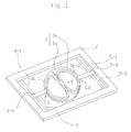
- Fig. 1 which is a rear-side perspective view illustrating a first embodiment of the one-dimensional optical deflector according to the presently disclosed subject matter
- this optical deflector is constructed by an optical deflecting mirror device 1, a support frame 2 supporting the optical deflecting mirror device 1, a pair of torsion bars 3-1 and 3-2 coupled between the support frame 2 and the optical deflecting mirror device 1, and two pairs of piezoelectric actuators 4-1 and 4-2; 5-1 and 5-2 serving as cantilevers, coupled between the support frame 2 and the torsion bars 3-1 and 3-2, for rocking the optical deflecting mirror device 1 around an X-axis through the torsion bars 3-1 and 3-2.
- the optical deflecting mirror device 1 is coupled to the torsion bars 3-1 and 3-2 at their coupling portions C1 and C2.
- the optical deflecting mirror device 1 includes a circular or elliptic mirror 1a with a reflective front surface, and a figure “8 "-shaped reinforcement rib 1b provided on a rear surface of the mirror 1a symmetrical with respect to the X-axis serving as a rocking axis.
- the figure “8 "-shaped reinforcement rib 1b includes ring-shaped reinforcement ribs 1b-1 and 1b-2 coupled to each other along the X-axis.
- the minimum distance between the figure “8 "-shaped reinforcement rib 1b and the outer circumference of the mirror 1a is about 40 ⁇ m.
- the thickness of the mirror 1a is the same as that of the torsion bars 3-1 and 3-2, i.e., about 40 ⁇ m.
- the figure "8 "-shaped reinforcement rib 1b is about 100 ⁇ m wide and about 150 to 200 ⁇ m thick.
- the support frame 2 is about 400 to 500 ⁇ m thick.
- the optical deflecting mirror device 1 can be driven at a higher speed than the required speed.
- the rigidity of the optical deflecting mirror device 1 having the figure "8 "-shaped reinforcement rib 1b is smaller than that of the optical deflecting mirror device 301' of Fig. 9 having the ring-shaped reinforcement rib 301b and the central reinforcement rib 301c; however, the reduction of the rigidity is compensated for by the X-shaped center portion of the figure "8 "-shaped reinforcement rib 1b. Therefore, the reduction of the rigidity is small, so that the increase of the dynamic face-deflection peak-to-valley amount D is small.
- the dynamic face-deflection peak-to-valley amount D of the optical deflecting mirror device 1 is about 25 nm (see Fig.
- the suppression of the dynamic face-deflection peak-to-valley amount D of the optical deflecting mirror device 1 can be realized simultaneously with the increase of the resonant frequency "f" of the optical deflecting mirror device 1.
- Fig. 2 which is a rear-side perspective view illustrating a second embodiment of the one-dimensional optical deflector according to the presently disclosed subject matter
- linear reinforcement ribs 1c-1 and 1c-2 are added to the elements of the optical deflecting mirror device 1 of Fig. 1 , to realize an optical deflecting mirror device 1'. That is, the linear reinforcement rib 1c-1 is coupled between the inner ends of the ring-shaped reinforcement rib 1b-1 along the X-axis, while the linear reinforcement rib 1c-2 is coupled between the inner ends of the ring-shaped reinforcement rib 1b-2 along the X-axis. Also, the width and thickness of the linear reinforcement ribs 1c-1 and 1c-2 are the same as those of the figure "8 "-shaped reinforcement rib 1b.
- the resonant frequency "f" of the optical deflecting mirror device 1' is slightly smaller than that of the optical deflecting mirror device 1 of Fig. 1 , i. e. , about 26.7 kHz as illustrated in Fig. 4 . Therefore, in the optical deflecting mirror device 1' of Fig. 2 , although the resonant frequency "f" is slightly low, the dynamic face-deflection peak-to-valley amount D is improved.
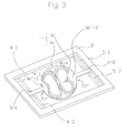
- Fig. 3 is a rear-side perspective view illustrating a third embodiment of the one-dimensional optical deflector according to the presently disclosed subject matter.
- an optical deflecting mirror device 1" is constructed by the mirror 1a and a figure “8 "-shaped reinforcement rib 1b'.
- the ring-shaped reinforcement ribs 1b-1 and 1b-2 of Fig. 1 are replaced by ring-shaped reinforcement ribs 1b'-1 and 1b'-2 whose end portions along the X-axis are recessed. Therefore, recess portions 1b"-1 and 1b"-2 are created at coupling portions C1' and C2' between the optical deflecting mirror device 1" and the torsion bars 3-1 and 3-2.
- the frontage of the recess portions 1b"-1 and 1b”-2 is about 200 to 250 ⁇ m long. As a result, a stress concentration at the coupling portions C1' and C2' can be relaxed, to thereby avoid the mechanical destruction thereof.
- the stress (in this case, the Mises stress) on the front side of the coupling portions C1 and C2 is isotropically small due to the absence of the figure “8 "-shaped reinforcement rib 1b, so that a stress slope on the front side of the coupling portions C1 and C2 is small.
- the stress distribution on the rear side of the coupling portions C1 and C2 is asymmetrical to the stress distribution on the front side of the coupling portions C1 and C2, so that the coupling portions C1 and C2, particularly, the torsion bars 3-1 and 3-2 would be mechanically broken.
- the rocking angle is larger than 10°
- the torsion bars 3-1 and 3-2 would often be mechanically broken.
- the torsion bars 3-1 and 3-2 would be mechanically broken.
- the stress (in this case, the Mises stress) on the rear side of the coupling portions C1' and C2' is isotropically large due to the presence of the recess portions 1b"-1 and 1b"-2 opposing the figure “8 "-shaped reinforcement rib 1b', so that a stress slope on the rear side of the coupling portions C1' and C2' is small.
- the stress distribution on the rear side of the coupling portions C1' and C2' is symmetrical to the stress distribution on the front side of the coupling portions C1' and C2', so that the coupling portions C1' and C2', particularly, the torsion bars 3-1 and 3-2 would not be mechanically broken.
- the rigidity of the optical deflecting mirror device 1" is slightly decreased to slightly increase the dynamic face-deflection peak-to-valley amount D to about 30 nm as illustrated in Fig. 4 .
- the moment of inertia is slightly increased, the resonant frequency "f” is slightly decreased to about 26.7 kHz, as illustrated in Fig. 4 .
- the one-dimensional optical deflectors of Figs. 1 , 2 and 3 can be applied to a two-dimensional optical deflector.
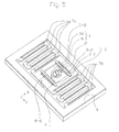
- Fig. 5 which is a front-side perspective view illustrating a two-dimensional optical deflector to which the one-dimensional optical deflector of Fig. 1 is applied
- the support frame 2 of Fig. 1 is replaced by an inner support frame 2' whose thickness is the same as that of the torsion bars 3-1 and 3-2.
- an outer support frame 6 is provided to surround the inner support frame 2'.
- a pair of meander-type piezoelectric actuators 7a and 7b coupled between the outer support frame 6 and the inner support frame 2' are a pair of meander-type piezoelectric actuators 7a and 7b.
- the outer support frame 6 is about 400 to 500 ⁇ m thick.
- the meander-type piezoelectric actuators. 7a and 7b can rock the mirror 1a around the Y-axis through the inner support frame 2'.
- a pair of outer torsion bars can be coupled between the outer support frame 6 and the inner support frame 2', and two pairs of piezoelectric actuators can be coupled between the outer support frame 6 and the outer torsion bars to rock the inner support frame 2' through the outer torsion bars along the Y-axis.
- the one-dimensional optical deflector of Fig. 2 or 3 can be applied to the two-dimensional optical deflector of Fig. 5 .
- only one torsion bar can be provided instead of the pair of torsion bars for rocking the mirror around the X-axis.
- only one meander-type actuator or only one outer torsion bar can be provided instead of the pair of meander-type actuators or the pair of outer torsion bars.
- electrostatic actuators or electromagnetic actuators can be provided instead of the piezoelectric actuators.
Landscapes
- Physics & Mathematics (AREA)
- Engineering & Computer Science (AREA)
- General Physics & Mathematics (AREA)
- Optics & Photonics (AREA)
- Mechanical Engineering (AREA)
- Computer Hardware Design (AREA)
- Microelectronics & Electronic Packaging (AREA)
- Mechanical Optical Scanning Systems (AREA)
- Micromachines (AREA)
- Mechanical Light Control Or Optical Switches (AREA)
Abstract
Description
- This application claims the priority benefit under 35 U.S.C. §119 to Japanese Patent Application No.
JP2013-191876 filed on September 17, 2013 - The presently disclosed subject matter relates to an optical deflector used in an optical scanner for a projector, a headlamp, a bar code reader, a laser printer, a laser head amplifier, a head-up display unit and the like, and, more particularly, to its optical deflecting mirror device.
- Recently, optical deflectors used in optical scanners have been micro electro mechanical system (MEMS) devices manufactured by semiconductor manufacturing technology and micro machine technology.
- In
Fig. 6 , which is a rear-side perspective view illustrating a first prior art optical deflector (see: Fig. 16 ofJP2001-249300 deflecting mirror device 101 constructed by only a single mirror is supported by torsion bars 102-1 and 102-2 to a support frame (not shown). Also, provided between the support frame and the torsion bars 102-1 and 102-2 are actuators (not shown) serving as cantilevers. Thus, the opticaldeflecting mirror device 101 can be rocked around an X-axis by the actuators. - In
Fig. 6 , since the thickness of the opticaldeflecting mirror device 101 is the same as that of the torsion bars 102-1 and 102-2, the opticaldeflecting mirror device 101 is very thin. As a result, the moment of inertia of the opticaldeflecting mirror device 101 is so small that the resonant frequency "f" of the opticaldeflecting mirror device 101 is very large. For example, when the thickness and diameter of the opticaldeflecting mirror device 101 are about 40 µm and about 1.2 mm, respectively, the resonant frequency "f" of the opticaldeflecting mirror device 101 is 30.0 kHz or more (see:Fig. 4 ). Thus, the resonant frequency "f" of the opticaldeflecting mirror device 101 becomes higher than a required resonant frequency fR (=26. 5kHz) in optical scanners for high definition projectors. That is, f > fR is satisfied, so that the opticaldeflecting mirror device 101 can be driven at a higher speed than a required speed. - In the first prior art optical deflector of
Fig. 6 , however, since the opticaldeflecting mirror device 101 is very thin, the rigidity of the opticaldeflecting mirror device 101 is very small. Therefore, when the rocking angle of the opticaldeflecting mirror device 101 is large, the opticaldeflecting mirror device 101 is greatly deformed in a bowl shape, so that the dynamic face-deflection peak-to-valley amount D is very large. For example, when the thickness and diameter of the opticaldeflecting mirror device 101 are about 40 µm and about 1. 2 mm, respectively, the dynamic face-deflection peak-to-valley amount D of the opticaldeflecting mirror device 101 is about 156 nm (see:Fig. 4 ). Thus, the dynamic face-deflection peak-to-valley amount D of the opticaldeflecting mirror device 101 becomes larger than a required dynamic face-deflection peak-to-valley amount DR (=45nm) in optical scanners for high definition projectors. That is, D < DR is not satisfied, so that the optical characteristics of reflected light of the opticaldeflecting mirror device 101 do not satisfy required optical characteristics in optical scanners for high definition projectors. Note that the required dynamic face-deflection peak-to-valley amount DR is defined by one-tenth of a wavelength (λ =450nm) of a laser beam irradiated onto optical deflecting mirror devices. - In
Fig. 7 , which is a rear-side perspective view illustrating a second prior art optical deflector (see:JP7-092409 deflecting mirror device 201 constructed by only a single mirror is thicker than torsion bars 202-1 and 202-2. Therefore, since the opticaldeflecting mirror device 201 is very thick, the rigidity of the opticaldeflecting mirror device 201 is very large. As a result, even when the rocking angle of the opticaldeflecting mirror device 201 is large, the opticaldeflecting mirror device 201 is slightly deformed in a bowl shape, so that the dynamic face-deflection peak-to-valley amount D is very small. For example, when the thickness and diameter of the opticaldeflecting mirror device 201 are about 200 µm and about 1.2 mm, respectively, the dynamic face-deflection peak-to-valley amount D of the opticaldeflecting mirror device 201 is several nm (see:Fig. 4 ). Thus, the dynamic face-deflection peak-to-valley amount D of the opticaldeflecting mirror device 201 becomes smaller than the required dynamic face-deflection peak-to-valley amount DR (=45nm) in optical scanners for high definition projectors. That is, D < DR is satisfied, so that the optical characteristics of reflected light of the opticaldeflecting mirror device 201 satisfy the required optical characteristics in optical scanners for high definition projectors. - In the second prior art optical deflector of
Fig. 7 , however, the moment of inertia of the opticaldeflecting mirror device 201 is so large that the resonant frequency "f" of the opticaldeflecting mirror device 201 is very small. For example, when the thickness and diameter of the opticaldeflecting mirror device 201 are about 200 µm and about 1.2 mm, respectively, the resonant frequency "f" of the opticaldeflecting mirror device 201 is 15 kHz or less (see:Fig. 4 ). Thus, the resonant frequency "f" of the opticaldeflecting mirror device 201 becomes lower than the required resonant frequency fR (=26.5kHz) in optical scanners for high definition projectors. That is, f > fR is not satisfied, so that it is impossible to drive the opticaldeflecting mirror device 201 at a higher speed than the required speed. - In
Fig. 8 , which is a rear-side perspective view illustrating a third prior art optical deflector (see:Fig. 3 ofJP2010-128116 deflecting mirror device 301 coupled to torsion bars 302-1 and 302-2 has amirror 301a with a reflective front surface and a ring-shaped reinforcement rib 301b provided on a back surface of themirror 301a. Therefore, the average thickness of the opticaldeflecting mirror device 301 is larger than that of the torsion bars 302-1 and 302-2. - In the third prior art optical deflector of
Fig. 8 , due to the presence of the ring-shaped reinforcement rib 301b, the rigidity of the opticaldeflecting mirror device 301 is larger than that of the opticaldeflecting mirror device 101 ofFig. 6 , but is smaller than that of the opticaldeflecting mirror device 201 ofFig. 7 . On the other hand, due to the presence of the ring-shaped reinforcement rib 301b, the resonant frequency "f" of the opticaldeflecting mirror device 301 is smaller than that of the opticaldeflecting mirror device 101 ofFig. 6 , but is larger than that of the opticaldeflecting mirror device 201 ofFig. 7 . For example, when the thickness and diameter of themirror 301a are about 40 µm and about 1.2 mm, respectively, and the width and height of the ring-shaped reinforcement rib 301b are about 100 µm and about 150 µm, respectively, the dynamic face-deflection peak-to-valley amount D of the opticaldeflecting mirror device 301 is about 80 nm and the resonant frequency "f" of the opticaldeflecting mirror device 301 is about 25.6 kHz (see:Fig. 4 ). - In the third prior art optical deflector of
Fig. 8 , however, since no rib is present at the center of themirror 301a, the rigidity of the opticaldeflecting mirror device 301 is still small. Therefore, when the rocking angle of the opticaldeflecting mirror device 301 is large, the opticaldeflecting mirror device 301 is greatly deformed in a bowl shape, so that the dynamic face-deflection peak-to-valley amount D is still large, i. e. , about 80 nm. Thus, the dynamic face-deflection peak-to-valley amount D of the opticaldeflecting mirror device 301 becomes larger than the required dynamic face-deflection peak-to-valley amount DR (=45nm) in optical scanners for high definition projectors. That is, D < DR is not satisfied, so that the optical characteristics of reflected light of the opticaldeflecting mirror device 301 do not satisfy the required optical characteristics in optical scanners for high definition projectors. - On the other hand, in the third prior art optical deflector of
Fig. 8 , as the ring-shaped reinforcement rib 301b is provided at the outer circumference of themirror 301a, the moment of inertia of the opticaldeflecting mirror device 301 is still large, so that the resonant frequency "f" of the opticaldeflecting mirror device 301 is still small. For example, the resonant frequency "f" of the opticaldeflecting mirror device 301 is about 25.6 kHz, as stated above. Thus, the resonant frequency "f" of the opticaldeflecting mirror device 301 becomes lower than the required resonant frequency fR (=26.5kHz) in optical scanners for high definition projectors. That is, f > fR is not satisfied, so that it is impossible to drive the opticaldeflecting mirror device 301 at a higher speed than the required speed. - In
Fig. 9 , which is a rear-side perspective view illustrating a comparative example of the optical deflector ofFig. 8 , the opticaldeflecting mirror device 301 ofFig. 8 is replaced by an optical deflecting mirror device 301' where a central reinforcement rib 301c along a Y-axis is added to the elements of the opticaldeflecting mirror device 301 ofFig. 8 . Therefore, the rigidity of the optical deflecting mirror device 301' is larger than the opticaldeflecting mirror device 301 ofFig. 8 , to reduce the bowl-like face-deformation of the optical deflecting mirror device 301'. Thus, the dynamic face-deflection peak-to-valley amount D is about 12 nm, which becomes smaller than the required dynamic face-deflection peak-to-valley amount DR; however, the resonant frequency "f" is about 25.3 kHz, which becomes lower than the required resonant frequency fR (see:Fig. 4 ). - According to the above-described prior art optical deflectors as illustrated in
Figs. 6, 7 and 8 and the comparative example as illustrated inFig. 9 , the suppression of the dynamic face-deflection peak-to-valley amount D of an optical deflecting mirror device has a trade-off relationship with the increase of the resonant frequency "f" of the optical deflecting mirror device. - The presently disclosed subject matter seeks to solve one or more of the above-described problems.
- According to the presently disclosed subject matter, an optical deflecting mirror device includes a mirror with a reflective front surface, and a
figure "8 "-shaped reinforcement rib provided on a rear surface of the mirror symmetrically along a rocking axis of the mirror. Thefigure "8 "-shaped reinforcement rib includes two ring-shaped reinforcement ribs coupled to each other along the rocking axis. - Thus, according to the presently disclosed subject matter, the suppression of the dynamic face-deflection peak-to-valley amount D can be realized simultaneously with the increase of the resonant frequency "f".
- The above and other advantages and features of the presently disclosed subject matter will be more apparent from the following description of certain embodiments, taken in conjunction with the accompanying drawings, as compared with the prior art and comparative example, wherein:
-
Fig. 1 is a rear-side perspective view illustrating a first embodiment of the one-dimensional optical deflector according to the presently disclosed subject matter; -
Fig. 2 is a rear-side perspective view illustrating a second embodiment of the one-dimensional optical deflector according to the presently disclosed subject matter; -
Fig. 3 is a rear-side perspective view illustrating a third embodiment of the one-dimensional optical deflector according to the presently disclosed subject matter; -
Fig. 4 is a diagram showing the dynamic face-deflection peak-to-valley amounts and resonant frequencies of the first, second and third embodiments as compared with the prior art and comparative example; -
Fig. 5 is a front-side perspective view illustrating a two-dimensional deflector to which the first embodiment of the one-dimensional optical deflector ofFig. 1 is applied; -
Fig. 6 is a rear-side perspective view illustrating a first prior art optical deflector; -
Fig. 7 is a rear-side perspective view illustrating a second prior art optical deflector; -
Fig. 8 is a rear-side perspective view illustrating a third prior art optical deflector; and -
Fig. 9 is a rear-side perspective view illustrating a comparative example of the third prior art optical deflector. - In
Fig. 1 , which is a rear-side perspective view illustrating a first embodiment of the one-dimensional optical deflector according to the presently disclosed subject matter, this optical deflector is constructed by an opticaldeflecting mirror device 1, asupport frame 2 supporting the opticaldeflecting mirror device 1, a pair of torsion bars 3-1 and 3-2 coupled between thesupport frame 2 and the opticaldeflecting mirror device 1, and two pairs of piezoelectric actuators 4-1 and 4-2; 5-1 and 5-2 serving as cantilevers, coupled between thesupport frame 2 and the torsion bars 3-1 and 3-2, for rocking the opticaldeflecting mirror device 1 around an X-axis through the torsion bars 3-1 and 3-2. The opticaldeflecting mirror device 1 is coupled to the torsion bars 3-1 and 3-2 at their coupling portions C1 and C2. - Also, the optical
deflecting mirror device 1 includes a circular orelliptic mirror 1a with a reflective front surface, and afigure "8 "-shapedreinforcement rib 1b provided on a rear surface of themirror 1a symmetrical with respect to the X-axis serving as a rocking axis. In this case, thefigure "8 "-shapedreinforcement rib 1b includes ring-shapedreinforcement ribs 1b-1 and 1b-2 coupled to each other along the X-axis. The minimum distance between thefigure "8 "-shapedreinforcement rib 1b and the outer circumference of themirror 1a is about 40 µm. Also, the thickness of themirror 1a is the same as that of the torsion bars 3-1 and 3-2, i.e., about 40 µm. Further, thefigure "8 "-shapedreinforcement rib 1b is about 100 µm wide and about 150 to 200 µm thick. On the other hand, thesupport frame 2 is about 400 to 500 µm thick. - In
Fig. 1 , thecentral reinforcement rib 301c ofFig. 9 and the farthest portions of the ring-shapedreinforcement rib 301b ofFig. 9 from the X-axis are removed to thereby realize thefigure "8 "-shapedreinforcement rib 1b which has an X-shaped center portion formed by crossed beams sloped at an angle of ±15 to 30 degrees with respect to a Y-axis. Thus, the moment of inertia of the opticaldeflecting mirror device 1 is much smaller than that of the optical deflecting mirror device 301' ofFig. 9 . For example, if the sizes of themirror 1a and thefigure "8 "-shapedreinforcement rib 1b are defined as stated above, the resonant frequency "f" of the opticaldeflecting mirror device 1 is about 26.8 kHz (seeFig. 4 ), which would satisfy the resonant frequency requirement where f>fR=26.5kHz. Thus, the opticaldeflecting mirror device 1 can be driven at a higher speed than the required speed. - On the other hand, the rigidity of the optical
deflecting mirror device 1 having thefigure "8 "-shapedreinforcement rib 1b is smaller than that of the optical deflecting mirror device 301' ofFig. 9 having the ring-shapedreinforcement rib 301b and thecentral reinforcement rib 301c; however, the reduction of the rigidity is compensated for by the X-shaped center portion of thefigure "8 "-shapedreinforcement rib 1b. Therefore, the reduction of the rigidity is small, so that the increase of the dynamic face-deflection peak-to-valley amount D is small. Actually, the dynamic face-deflection peak-to-valley amount D of the opticaldeflecting mirror device 1 is about 25 nm (seeFig. 4 ) which is a little larger than the dynamic face-deflection peak-to-valley amount D (=12nm) of the optical deflecting mirror device 301' ofFig. 9 , thus satisfying the dynamic face-deflection peak-to-valley amount requirement where D<DR=45nm. As a result, the optical characteristics of reflected light of the opticaldeflecting mirror device 1 would satisfy the required optical characteristics in optical scanners for high definition projectors. - Thus, according to the first embodiment, the suppression of the dynamic face-deflection peak-to-valley amount D of the optical
deflecting mirror device 1 can be realized simultaneously with the increase of the resonant frequency "f" of the opticaldeflecting mirror device 1. - In
Fig. 2 , which is a rear-side perspective view illustrating a second embodiment of the one-dimensional optical deflector according to the presently disclosed subject matter,linear reinforcement ribs 1c-1 and 1c-2 are added to the elements of the opticaldeflecting mirror device 1 ofFig. 1 , to realize an optical deflecting mirror device 1'. That is, thelinear reinforcement rib 1c-1 is coupled between the inner ends of the ring-shapedreinforcement rib 1b-1 along the X-axis, while thelinear reinforcement rib 1c-2 is coupled between the inner ends of the ring-shapedreinforcement rib 1b-2 along the X-axis. Also, the width and thickness of thelinear reinforcement ribs 1c-1 and 1c-2 are the same as those of thefigure "8 "-shapedreinforcement rib 1b. - In
Fig. 2 , due to the presence of thelinear reinforcement ribs 1c-1 and 1c-2, the rigidity of the optical deflecting mirror device 1' is larger than that of the opticaldeflecting mirror device 1 ofFig. 1 , so that the dynamic face-deflection peak-to-valley amount D is decreased to about 20 nm as illustrated inFig. 4 . On the other hand, since thelinear reinforcement ribs 1c-1 and 1c-2 are arranged along the X-axis (rocking axis), the increase of the moment of inertia of the optical deflecting mirror device 1' as compared with that of the opticaldeflecting mirror device 1 ofFig. 1 is small. As a result, the resonant frequency "f" of the optical deflecting mirror device 1' is slightly smaller than that of the opticaldeflecting mirror device 1 ofFig. 1 , i. e. , about 26.7 kHz as illustrated inFig. 4 . Therefore, in the optical deflecting mirror device 1' ofFig. 2 , although the resonant frequency "f" is slightly low, the dynamic face-deflection peak-to-valley amount D is improved. Thus, the optical characteristics of reflected light of the optical deflecting mirror device 1' would satisfy the required optical characteristics where D<DR=45nm in optical scanners for high definition projectors, and the resonant frequency "f" of the optical deflecting mirror device 1' would satisfy the resonant frequency requirement where f>fR=26.5kHz, thus, driving the optical deflecting mirror device 1' at a higher speed than the required speed. -
Fig. 3 is a rear-side perspective view illustrating a third embodiment of the one-dimensional optical deflector according to the presently disclosed subject matter. - In
Fig. 3 , an opticaldeflecting mirror device 1" is constructed by themirror 1a and afigure "8 "-shapedreinforcement rib 1b'. In thefigure "8 "-shapedreinforcement rib 1b', the ring-shapedreinforcement ribs 1b-1 and 1b-2 ofFig. 1 are replaced by ring-shapedreinforcement ribs 1b'-1 and 1b'-2 whose end portions along the X-axis are recessed. Therefore,recess portions 1b"-1 and 1b"-2 are created at coupling portions C1' and C2' between the opticaldeflecting mirror device 1" and the torsion bars 3-1 and 3-2. The frontage of therecess portions 1b"-1 and 1b"-2 is about 200 to 250 µ m long. As a result, a stress concentration at the coupling portions C1' and C2' can be relaxed, to thereby avoid the mechanical destruction thereof. - In the optical deflector of
Fig. 1 , note that, when the opticaldeflecting mirror device 1 is rocked through the torsion bars 3-1 and 3-2, a stress concentration occurs at the coupling portions C1 and C2. Concretely, the stress (in this case, the Mises stress) on the rear side of the coupling portions C1 and C2 is anisotropically large due to the presence of thefigure "8 "-shapedreinforcement rib 1b, so that a stress slope on the rear side of the coupling portions C1 and C2 is large. On the other hand, the stress (in this case, the Mises stress) on the front side of the coupling portions C1 and C2 is isotropically small due to the absence of thefigure "8 "-shapedreinforcement rib 1b, so that a stress slope on the front side of the coupling portions C1 and C2 is small. As a result, the stress distribution on the rear side of the coupling portions C1 and C2 is asymmetrical to the stress distribution on the front side of the coupling portions C1 and C2, so that the coupling portions C1 and C2, particularly, the torsion bars 3-1 and 3-2 would be mechanically broken. For example, when the rocking angle is larger than 10° , the torsion bars 3-1 and 3-2 would often be mechanically broken. Similarly, in the optical deflector ofFig. 2 , the torsion bars 3-1 and 3-2 would be mechanically broken. - Conversely, in the optical deflector of
Fig. 3 , the stress (in this case, the Mises stress) on the rear side of the coupling portions C1' and C2' is isotropically large due to the presence of therecess portions 1b"-1 and 1b"-2 opposing thefigure "8 "-shapedreinforcement rib 1b', so that a stress slope on the rear side of the coupling portions C1' and C2' is small. As a result, the stress distribution on the rear side of the coupling portions C1' and C2' is symmetrical to the stress distribution on the front side of the coupling portions C1' and C2', so that the coupling portions C1' and C2', particularly, the torsion bars 3-1 and 3-2 would not be mechanically broken. - In the optical deflector of
Fig. 3 , since therecess portions 1b"-1 and 1b"-2 are provided in thefigure "8 "-shapedreinforcement rib 1b', the rigidity of the opticaldeflecting mirror device 1" is slightly decreased to slightly increase the dynamic face-deflection peak-to-valley amount D to about 30 nm as illustrated inFig. 4 . Also, the moment of inertia is slightly increased, the resonant frequency "f" is slightly decreased to about 26.7 kHz, as illustrated inFig. 4 . However, the opticaldeflecting mirror device 1" would satisfy the required dynamic face-deflection peak-to-valley amount D where D<DR=45nm and the required resonant frequency where f>fR=26.5kHz. - The one-dimensional optical deflectors of
Figs. 1 ,2 and3 can be applied to a two-dimensional optical deflector. - In
Fig. 5 , which is a front-side perspective view illustrating a two-dimensional optical deflector to which the one-dimensional optical deflector ofFig. 1 is applied, thesupport frame 2 ofFig. 1 is replaced by an inner support frame 2' whose thickness is the same as that of the torsion bars 3-1 and 3-2. Additionally, anouter support frame 6 is provided to surround the inner support frame 2'. Further, coupled between theouter support frame 6 and the inner support frame 2' are a pair of meander-type piezoelectric actuators outer support frame 6 is about 400 to 500 µm thick. Thus, the meander-type piezoelectric actuators. 7a and 7b can rock themirror 1a around the Y-axis through the inner support frame 2'. - In
Fig. 5 , instead of the meander-type piezoelectric actuators outer support frame 6 and the inner support frame 2', and two pairs of piezoelectric actuators can be coupled between theouter support frame 6 and the outer torsion bars to rock the inner support frame 2' through the outer torsion bars along the Y-axis. - Also, the one-dimensional optical deflector of
Fig. 2 or3 can be applied to the two-dimensional optical deflector ofFig. 5 . - Further, in the above-described embodiments, only one torsion bar can be provided instead of the pair of torsion bars for rocking the mirror around the X-axis. Similarly, only one meander-type actuator or only one outer torsion bar can be provided instead of the pair of meander-type actuators or the pair of outer torsion bars.
- Furthermore, in the above-described embodiments, electrostatic actuators or electromagnetic actuators can be provided instead of the piezoelectric actuators.
- It will be apparent to those skilled in the art that various modifications and variations can be made in the presently disclosed subject matter without departing from the spirit or scope of the presently disclosed subject matter. Thus, it is intended that the presently disclosed subject matter covers the modifications and variations of the presently disclosed subject matter provided they come within the scope of the appended claims and their equivalents. All related or prior art references described above and in the Background section of the present specification are hereby incorporated in their entirety by reference.
Claims (8)
- An optical deflecting mirror device comprising:a mirror (1a) with a reflective front surface;
anda figure "8"-shaped reinforcement rib (1b, 1b') provided on a rear surface of said mirror (1a) symmetrically along a rocking axis (X) of said mirror (1a), said figure "8"-shaped reinforcement rib (1b, 1b') including two ring-shaped reinforcement ribs (1b-1, 1b-2; 1b'-1, 1b'-2) coupled to each other along said rocking axis (X). - The optical deflecting mirror device as set forth in claim 1, further comprising two linear reinforcement ribs (1c-1, 1c-2) provided on the rear-side surface of said mirror (1a) along said rocking axis (X),
each of said linear reinforcement ribs (1c-1, 1c-2) being coupled between two inner ends of one of said ring-shaped reinforcement ribs (1b-1, 1b-2). - The optical deflecting mirror device as set forth in claim 1, wherein end portions of said figure "8"-shaped reinforcement rib (1b') are recessed.
- The optical deflecting mirror device as set forth in claim 1, wherein said mirror (1a) is circular.
- The optical deflecting mirror device as set forth in claim 1, wherein said mirror (1a) is elliptical.
- The optical deflecting mirror device as set forth in claim 1, being adapted to an optical deflector,
wherein said optical deflector comprises
a first support frame (2, 2') to support said mirror (1a);
at least one first torsion bar (3-1, 3-2) coupled between said first support frame (2, 2') and said mirror (1a);
a first actuator (4-1, 4-2; 5-1, 5-2), coupled between said first support frame (2, 2') and said first torsion bar (3-1, 3-2), to rock said mirror (1a) around said first torsion bar (3-1, 3-2); and
a figure "8"-shaped reinforcement rib (1b, 1b') provided on a rear surface of said mirror (1a) symmetrically along said torsion bar (3-1, 3-2), said figure "8"-shaped reinforcement rib (1b, 1b') including two ring-shaped reinforcement ribs (1b-1, 1b-2; 1b'-1, 1b'-2) coupled to each other along said first torsion bar (3-1, 3-2). - The optical deflector as set forth in claim 6,
wherein said optical deflector further comprises:a second support frame (6) to support said first support frame (2');at least one second actuator (7a, 7b), coupled between said second support frame (6) and said first support frame (2'), to rock said first support frame (2') around an axis (Y) perpendicular to said first torsion bar (3-1, 3-2). - The optical deflector as set forth in claim 7,
wherein said second actuator (7a, 7b) comprises a meander-type actuator.
Applications Claiming Priority (1)
| Application Number | Priority Date | Filing Date | Title |
|---|---|---|---|
| JP2013191876A JP6261923B2 (en) | 2013-09-17 | 2013-09-17 | Optical deflection mirror and optical deflector using the same |
Publications (2)
| Publication Number | Publication Date |
|---|---|
| EP2857347A1 true EP2857347A1 (en) | 2015-04-08 |
| EP2857347B1 EP2857347B1 (en) | 2018-03-07 |
Family
ID=51483352
Family Applications (1)
| Application Number | Title | Priority Date | Filing Date |
|---|---|---|---|
| EP14183759.1A Active EP2857347B1 (en) | 2013-09-17 | 2014-09-05 | Optical deflecting mirror device having figure "8"-shaped rib and optical deflector |
Country Status (4)
| Country | Link |
|---|---|
| US (1) | US20150077824A1 (en) |
| EP (1) | EP2857347B1 (en) |
| JP (1) | JP6261923B2 (en) |
| CN (1) | CN104459996B (en) |
Cited By (2)
| Publication number | Priority date | Publication date | Assignee | Title |
|---|---|---|---|---|
| EP3489695A1 (en) * | 2017-11-28 | 2019-05-29 | Seiko Epson Corporation | Physical quantity sensor , electronic apparatus and vehicle comprising the same |
| WO2020205373A1 (en) * | 2019-04-02 | 2020-10-08 | Microsoft Technology Licensing, Llc | Display device with compact scanning mirror |
Families Citing this family (6)
| Publication number | Priority date | Publication date | Assignee | Title |
|---|---|---|---|---|
| JP6390508B2 (en) * | 2015-05-07 | 2018-09-19 | 株式会社デンソー | Optical scanning device |
| CN111344622A (en) * | 2017-11-15 | 2020-06-26 | 浜松光子学株式会社 | Method for manufacturing optical device |
| CN112204449B (en) * | 2018-06-14 | 2022-06-17 | 奥林巴斯株式会社 | Optical deflector and scanning laser microscope |
| IT202000001411A1 (en) * | 2020-01-24 | 2021-07-24 | St Microelectronics Srl | PROCESSING METHOD OF A SLICE FOR THE MANUFACTURE OF AN OSCILLATING STRUCTURE SUCH AS A MICRO-MIRROR |
| WO2021181618A1 (en) * | 2020-03-12 | 2021-09-16 | 三菱電機株式会社 | Optical scanning device, distance measuring device, and method for manufacturing optical scanning device |
| DE102023132557A1 (en) * | 2023-11-22 | 2025-05-22 | Tdk Electronics Ag | Microelectromechanical mirror, method for operating a microelectromechanical mirror, projection device and method for producing a micromechanical mirror |
Citations (8)
| Publication number | Priority date | Publication date | Assignee | Title |
|---|---|---|---|---|
| JPH0792409A (en) | 1993-09-27 | 1995-04-07 | Canon Inc | Optical scanner |
| JP2001249300A (en) | 2000-03-06 | 2001-09-14 | Anritsu Corp | Optical scanner |
| US20050162724A1 (en) * | 2002-11-08 | 2005-07-28 | Orcutt John W. | Torsional hinged mirror assembly with central spines and perimeter ridges to reduce flexing |
| WO2008089786A1 (en) * | 2007-01-23 | 2008-07-31 | Fraunhofer-Gesellschaft zur Förderung der angewandten Forschung e.V. | Micromechanical component having increased stiffness, and method for the production of the same |
| US20090080051A1 (en) * | 2007-09-21 | 2009-03-26 | Samsung Electronics Co., Ltd. | Microactuator |
| JP2010128116A (en) | 2008-11-27 | 2010-06-10 | Ricoh Co Ltd | Optical scanner |
| US20120162739A1 (en) * | 2010-12-22 | 2012-06-28 | Mitsumi Electric Co., Ltd. | Optical scanning device |
| JP2013191876A (en) | 2013-05-27 | 2013-09-26 | Megaopto Co Ltd | Optical fiber laser |
Family Cites Families (7)
| Publication number | Priority date | Publication date | Assignee | Title |
|---|---|---|---|---|
| US7485485B2 (en) * | 2004-02-09 | 2009-02-03 | Microvision, Inc. | Method and apparatus for making a MEMS scanner |
| JPWO2005109076A1 (en) * | 2004-05-11 | 2008-03-21 | 住友精密工業株式会社 | Electrostatic drive type MEMS mirror scanner |
| US7359107B2 (en) * | 2006-03-31 | 2008-04-15 | Texas Instruments Incorporated | Analog MEMS with non-linear support |
| WO2008107870A1 (en) * | 2007-03-06 | 2008-09-12 | Btendo Ltd. | A mems device having reduced deformations |
| JP4980990B2 (en) * | 2008-06-25 | 2012-07-18 | パナソニック株式会社 | Movable structure and micromirror device using the same |
| JP5775409B2 (en) * | 2011-09-29 | 2015-09-09 | スタンレー電気株式会社 | Manufacturing method of optical scanner |
| JP5857602B2 (en) * | 2011-10-03 | 2016-02-10 | ミツミ電機株式会社 | Optical scanning device |
-
2013
- 2013-09-17 JP JP2013191876A patent/JP6261923B2/en active Active
-
2014
- 2014-08-20 US US14/464,393 patent/US20150077824A1/en not_active Abandoned
- 2014-09-05 EP EP14183759.1A patent/EP2857347B1/en active Active
- 2014-09-16 CN CN201410472156.XA patent/CN104459996B/en active Active
Patent Citations (8)
| Publication number | Priority date | Publication date | Assignee | Title |
|---|---|---|---|---|
| JPH0792409A (en) | 1993-09-27 | 1995-04-07 | Canon Inc | Optical scanner |
| JP2001249300A (en) | 2000-03-06 | 2001-09-14 | Anritsu Corp | Optical scanner |
| US20050162724A1 (en) * | 2002-11-08 | 2005-07-28 | Orcutt John W. | Torsional hinged mirror assembly with central spines and perimeter ridges to reduce flexing |
| WO2008089786A1 (en) * | 2007-01-23 | 2008-07-31 | Fraunhofer-Gesellschaft zur Förderung der angewandten Forschung e.V. | Micromechanical component having increased stiffness, and method for the production of the same |
| US20090080051A1 (en) * | 2007-09-21 | 2009-03-26 | Samsung Electronics Co., Ltd. | Microactuator |
| JP2010128116A (en) | 2008-11-27 | 2010-06-10 | Ricoh Co Ltd | Optical scanner |
| US20120162739A1 (en) * | 2010-12-22 | 2012-06-28 | Mitsumi Electric Co., Ltd. | Optical scanning device |
| JP2013191876A (en) | 2013-05-27 | 2013-09-26 | Megaopto Co Ltd | Optical fiber laser |
Cited By (6)
| Publication number | Priority date | Publication date | Assignee | Title |
|---|---|---|---|---|
| EP3489695A1 (en) * | 2017-11-28 | 2019-05-29 | Seiko Epson Corporation | Physical quantity sensor , electronic apparatus and vehicle comprising the same |
| CN109839515A (en) * | 2017-11-28 | 2019-06-04 | 精工爱普生株式会社 | Physical quantity transducer, e-machine and moving body |
| EP3726226A1 (en) * | 2017-11-28 | 2020-10-21 | Seiko Epson Corporation | Physical quantity sensor, electronic apparatus and vehicle comprising such a physical quantitiy sensor |
| US10900784B2 (en) | 2017-11-28 | 2021-01-26 | Seiko Epson Corporation | Physical quantity sensor, physical quantity sensor device, composite sensor device, inertial measurement unit, vehicle positioning apparatus, portable electronic apparatus, electronic apparatus, and vehicle |
| WO2020205373A1 (en) * | 2019-04-02 | 2020-10-08 | Microsoft Technology Licensing, Llc | Display device with compact scanning mirror |
| US11360299B2 (en) | 2019-04-02 | 2022-06-14 | Microsoft Technology Licensing, Llc | Display device with compact scanning mirror |
Also Published As
| Publication number | Publication date |
|---|---|
| CN104459996B (en) | 2018-07-10 |
| US20150077824A1 (en) | 2015-03-19 |
| JP6261923B2 (en) | 2018-01-17 |
| EP2857347B1 (en) | 2018-03-07 |
| CN104459996A (en) | 2015-03-25 |
| JP2015059976A (en) | 2015-03-30 |
Similar Documents
| Publication | Publication Date | Title |
|---|---|---|
| US20150077824A1 (en) | Optical deflecting mirror device having figure "8"-shaped rib and optical deflector | |
| US9097895B2 (en) | Optical deflector including mirror with recessed rib on its rear surface | |
| US9575313B2 (en) | Optical deflector including mirror with extended reinforcement rib coupled to protruded portions of torsion bar | |
| US8837029B2 (en) | Optical scanning device | |
| US9519137B2 (en) | Optical deflector including inner frame with circumferential rib and branch ribs | |
| US7864392B2 (en) | Microscanner and optical equipment with the same | |
| US20070269199A1 (en) | Driving device, optical scanning device, and object information detecting device | |
| EP2962984B1 (en) | Optical deflection apparatus, image forming apparatus, image display apparatus, moving body apparatus, and adjusting method of optical deflection apparatus | |
| US9323048B2 (en) | Optical deflector including meander-type piezoelectric actuators coupled by crossing bars therebetween | |
| US9436000B2 (en) | Optical deflector including meander-type piezoelectric actuators and ill-balanced mirror structure | |
| JP2014126725A (en) | Scanning mirror device | |
| JP2017116842A (en) | Optical deflector and image projection apparatus | |
| EP1881358A1 (en) | Scanner | |
| US9097894B2 (en) | Optical deflector including four coupling bars between support body and frame | |
| JP5585478B2 (en) | MEMS element for optical deflection | |
| KR100707133B1 (en) | Mirror structure and optical scanner including the same | |
| JP2003262803A (en) | Movable structure, and deflecting mirror element, optical switch element, and shape variable mirror each using the same | |
| US12332427B2 (en) | Light deflector | |
| JP2010281853A (en) | Optical deflection apparatus, image forming apparatus, and image display apparatus | |
| WO2022191046A1 (en) | Mirror actuator | |
| JP2020126142A (en) | Optical scanning device and optical scanning method | |
| WO2019167615A1 (en) | Optical deflector | |
| JP2016045336A (en) | Movable structure and optical scanning device using the same | |
| JP2008003307A (en) | Optical scanning device |
Legal Events
| Date | Code | Title | Description |
|---|---|---|---|
| PUAI | Public reference made under article 153(3) epc to a published international application that has entered the european phase |
Free format text: ORIGINAL CODE: 0009012 |
|
| 17P | Request for examination filed |
Effective date: 20140905 |
|
| AK | Designated contracting states |
Kind code of ref document: A1 Designated state(s): AL AT BE BG CH CY CZ DE DK EE ES FI FR GB GR HR HU IE IS IT LI LT LU LV MC MK MT NL NO PL PT RO RS SE SI SK SM TR |
|
| AX | Request for extension of the european patent |
Extension state: BA ME |
|
| R17P | Request for examination filed (corrected) |
Effective date: 20151008 |
|
| RBV | Designated contracting states (corrected) |
Designated state(s): AL AT BE BG CH CY CZ DE DK EE ES FI FR GB GR HR HU IE IS IT LI LT LU LV MC MK MT NL NO PL PT RO RS SE SI SK SM TR |
|
| 17Q | First examination report despatched |
Effective date: 20161122 |
|
| GRAP | Despatch of communication of intention to grant a patent |
Free format text: ORIGINAL CODE: EPIDOSNIGR1 |
|
| INTG | Intention to grant announced |
Effective date: 20170925 |
|
| GRAS | Grant fee paid |
Free format text: ORIGINAL CODE: EPIDOSNIGR3 |
|
| GRAA | (expected) grant |
Free format text: ORIGINAL CODE: 0009210 |
|
| AK | Designated contracting states |
Kind code of ref document: B1 Designated state(s): AL AT BE BG CH CY CZ DE DK EE ES FI FR GB GR HR HU IE IS IT LI LT LU LV MC MK MT NL NO PL PT RO RS SE SI SK SM TR |
|
| REG | Reference to a national code |
Ref country code: GB Ref legal event code: FG4D |
|
| REG | Reference to a national code |
Ref country code: CH Ref legal event code: EP Ref country code: AT Ref legal event code: REF Ref document number: 976327 Country of ref document: AT Kind code of ref document: T Effective date: 20180315 |
|
| REG | Reference to a national code |
Ref country code: DE Ref legal event code: R096 Ref document number: 602014021897 Country of ref document: DE |
|
| REG | Reference to a national code |
Ref country code: IE Ref legal event code: FG4D |
|
| REG | Reference to a national code |
Ref country code: NL Ref legal event code: MP Effective date: 20180307 |
|
| REG | Reference to a national code |
Ref country code: LT Ref legal event code: MG4D |
|
| PG25 | Lapsed in a contracting state [announced via postgrant information from national office to epo] |
Ref country code: NO Free format text: LAPSE BECAUSE OF FAILURE TO SUBMIT A TRANSLATION OF THE DESCRIPTION OR TO PAY THE FEE WITHIN THE PRESCRIBED TIME-LIMIT Effective date: 20180607 Ref country code: LT Free format text: LAPSE BECAUSE OF FAILURE TO SUBMIT A TRANSLATION OF THE DESCRIPTION OR TO PAY THE FEE WITHIN THE PRESCRIBED TIME-LIMIT Effective date: 20180307 Ref country code: FI Free format text: LAPSE BECAUSE OF FAILURE TO SUBMIT A TRANSLATION OF THE DESCRIPTION OR TO PAY THE FEE WITHIN THE PRESCRIBED TIME-LIMIT Effective date: 20180307 Ref country code: CY Free format text: LAPSE BECAUSE OF FAILURE TO SUBMIT A TRANSLATION OF THE DESCRIPTION OR TO PAY THE FEE WITHIN THE PRESCRIBED TIME-LIMIT Effective date: 20180307 Ref country code: ES Free format text: LAPSE BECAUSE OF FAILURE TO SUBMIT A TRANSLATION OF THE DESCRIPTION OR TO PAY THE FEE WITHIN THE PRESCRIBED TIME-LIMIT Effective date: 20180307 Ref country code: HR Free format text: LAPSE BECAUSE OF FAILURE TO SUBMIT A TRANSLATION OF THE DESCRIPTION OR TO PAY THE FEE WITHIN THE PRESCRIBED TIME-LIMIT Effective date: 20180307 |
|
| REG | Reference to a national code |
Ref country code: AT Ref legal event code: MK05 Ref document number: 976327 Country of ref document: AT Kind code of ref document: T Effective date: 20180307 |
|
| REG | Reference to a national code |
Ref country code: FR Ref legal event code: PLFP Year of fee payment: 5 |
|
| PG25 | Lapsed in a contracting state [announced via postgrant information from national office to epo] |
Ref country code: RS Free format text: LAPSE BECAUSE OF FAILURE TO SUBMIT A TRANSLATION OF THE DESCRIPTION OR TO PAY THE FEE WITHIN THE PRESCRIBED TIME-LIMIT Effective date: 20180307 Ref country code: BG Free format text: LAPSE BECAUSE OF FAILURE TO SUBMIT A TRANSLATION OF THE DESCRIPTION OR TO PAY THE FEE WITHIN THE PRESCRIBED TIME-LIMIT Effective date: 20180607 Ref country code: SE Free format text: LAPSE BECAUSE OF FAILURE TO SUBMIT A TRANSLATION OF THE DESCRIPTION OR TO PAY THE FEE WITHIN THE PRESCRIBED TIME-LIMIT Effective date: 20180307 Ref country code: LV Free format text: LAPSE BECAUSE OF FAILURE TO SUBMIT A TRANSLATION OF THE DESCRIPTION OR TO PAY THE FEE WITHIN THE PRESCRIBED TIME-LIMIT Effective date: 20180307 Ref country code: GR Free format text: LAPSE BECAUSE OF FAILURE TO SUBMIT A TRANSLATION OF THE DESCRIPTION OR TO PAY THE FEE WITHIN THE PRESCRIBED TIME-LIMIT Effective date: 20180608 |
|
| PG25 | Lapsed in a contracting state [announced via postgrant information from national office to epo] |
Ref country code: PL Free format text: LAPSE BECAUSE OF FAILURE TO SUBMIT A TRANSLATION OF THE DESCRIPTION OR TO PAY THE FEE WITHIN THE PRESCRIBED TIME-LIMIT Effective date: 20180307 Ref country code: NL Free format text: LAPSE BECAUSE OF FAILURE TO SUBMIT A TRANSLATION OF THE DESCRIPTION OR TO PAY THE FEE WITHIN THE PRESCRIBED TIME-LIMIT Effective date: 20180307 Ref country code: IT Free format text: LAPSE BECAUSE OF FAILURE TO SUBMIT A TRANSLATION OF THE DESCRIPTION OR TO PAY THE FEE WITHIN THE PRESCRIBED TIME-LIMIT Effective date: 20180307 Ref country code: RO Free format text: LAPSE BECAUSE OF FAILURE TO SUBMIT A TRANSLATION OF THE DESCRIPTION OR TO PAY THE FEE WITHIN THE PRESCRIBED TIME-LIMIT Effective date: 20180307 Ref country code: EE Free format text: LAPSE BECAUSE OF FAILURE TO SUBMIT A TRANSLATION OF THE DESCRIPTION OR TO PAY THE FEE WITHIN THE PRESCRIBED TIME-LIMIT Effective date: 20180307 Ref country code: AL Free format text: LAPSE BECAUSE OF FAILURE TO SUBMIT A TRANSLATION OF THE DESCRIPTION OR TO PAY THE FEE WITHIN THE PRESCRIBED TIME-LIMIT Effective date: 20180307 |
|
| PG25 | Lapsed in a contracting state [announced via postgrant information from national office to epo] |
Ref country code: CZ Free format text: LAPSE BECAUSE OF FAILURE TO SUBMIT A TRANSLATION OF THE DESCRIPTION OR TO PAY THE FEE WITHIN THE PRESCRIBED TIME-LIMIT Effective date: 20180307 Ref country code: SK Free format text: LAPSE BECAUSE OF FAILURE TO SUBMIT A TRANSLATION OF THE DESCRIPTION OR TO PAY THE FEE WITHIN THE PRESCRIBED TIME-LIMIT Effective date: 20180307 Ref country code: SM Free format text: LAPSE BECAUSE OF FAILURE TO SUBMIT A TRANSLATION OF THE DESCRIPTION OR TO PAY THE FEE WITHIN THE PRESCRIBED TIME-LIMIT Effective date: 20180307 Ref country code: AT Free format text: LAPSE BECAUSE OF FAILURE TO SUBMIT A TRANSLATION OF THE DESCRIPTION OR TO PAY THE FEE WITHIN THE PRESCRIBED TIME-LIMIT Effective date: 20180307 |
|
| REG | Reference to a national code |
Ref country code: DE Ref legal event code: R097 Ref document number: 602014021897 Country of ref document: DE |
|
| PG25 | Lapsed in a contracting state [announced via postgrant information from national office to epo] |
Ref country code: PT Free format text: LAPSE BECAUSE OF FAILURE TO SUBMIT A TRANSLATION OF THE DESCRIPTION OR TO PAY THE FEE WITHIN THE PRESCRIBED TIME-LIMIT Effective date: 20180709 |
|
| PLBE | No opposition filed within time limit |
Free format text: ORIGINAL CODE: 0009261 |
|
| STAA | Information on the status of an ep patent application or granted ep patent |
Free format text: STATUS: NO OPPOSITION FILED WITHIN TIME LIMIT |
|
| PG25 | Lapsed in a contracting state [announced via postgrant information from national office to epo] |
Ref country code: DK Free format text: LAPSE BECAUSE OF FAILURE TO SUBMIT A TRANSLATION OF THE DESCRIPTION OR TO PAY THE FEE WITHIN THE PRESCRIBED TIME-LIMIT Effective date: 20180307 |
|
| 26N | No opposition filed |
Effective date: 20181210 |
|
| PG25 | Lapsed in a contracting state [announced via postgrant information from national office to epo] |
Ref country code: SI Free format text: LAPSE BECAUSE OF FAILURE TO SUBMIT A TRANSLATION OF THE DESCRIPTION OR TO PAY THE FEE WITHIN THE PRESCRIBED TIME-LIMIT Effective date: 20180307 |
|
| PG25 | Lapsed in a contracting state [announced via postgrant information from national office to epo] |
Ref country code: MC Free format text: LAPSE BECAUSE OF FAILURE TO SUBMIT A TRANSLATION OF THE DESCRIPTION OR TO PAY THE FEE WITHIN THE PRESCRIBED TIME-LIMIT Effective date: 20180307 |
|
| REG | Reference to a national code |
Ref country code: CH Ref legal event code: PL |
|
| REG | Reference to a national code |
Ref country code: BE Ref legal event code: MM Effective date: 20180930 |
|
| REG | Reference to a national code |
Ref country code: IE Ref legal event code: MM4A |
|
| PG25 | Lapsed in a contracting state [announced via postgrant information from national office to epo] |
Ref country code: LU Free format text: LAPSE BECAUSE OF NON-PAYMENT OF DUE FEES Effective date: 20180905 |
|
| PG25 | Lapsed in a contracting state [announced via postgrant information from national office to epo] |
Ref country code: IE Free format text: LAPSE BECAUSE OF NON-PAYMENT OF DUE FEES Effective date: 20180905 |
|
| PG25 | Lapsed in a contracting state [announced via postgrant information from national office to epo] |
Ref country code: BE Free format text: LAPSE BECAUSE OF NON-PAYMENT OF DUE FEES Effective date: 20180930 Ref country code: CH Free format text: LAPSE BECAUSE OF NON-PAYMENT OF DUE FEES Effective date: 20180930 Ref country code: LI Free format text: LAPSE BECAUSE OF NON-PAYMENT OF DUE FEES Effective date: 20180930 |
|
| PG25 | Lapsed in a contracting state [announced via postgrant information from national office to epo] |
Ref country code: MT Free format text: LAPSE BECAUSE OF NON-PAYMENT OF DUE FEES Effective date: 20180905 |
|
| PG25 | Lapsed in a contracting state [announced via postgrant information from national office to epo] |
Ref country code: TR Free format text: LAPSE BECAUSE OF FAILURE TO SUBMIT A TRANSLATION OF THE DESCRIPTION OR TO PAY THE FEE WITHIN THE PRESCRIBED TIME-LIMIT Effective date: 20180307 |
|
| PG25 | Lapsed in a contracting state [announced via postgrant information from national office to epo] |
Ref country code: HU Free format text: LAPSE BECAUSE OF FAILURE TO SUBMIT A TRANSLATION OF THE DESCRIPTION OR TO PAY THE FEE WITHIN THE PRESCRIBED TIME-LIMIT; INVALID AB INITIO Effective date: 20140905 |
|
| PG25 | Lapsed in a contracting state [announced via postgrant information from national office to epo] |
Ref country code: MK Free format text: LAPSE BECAUSE OF NON-PAYMENT OF DUE FEES Effective date: 20180307 |
|
| PG25 | Lapsed in a contracting state [announced via postgrant information from national office to epo] |
Ref country code: IS Free format text: LAPSE BECAUSE OF FAILURE TO SUBMIT A TRANSLATION OF THE DESCRIPTION OR TO PAY THE FEE WITHIN THE PRESCRIBED TIME-LIMIT Effective date: 20180707 |
|
| PGFP | Annual fee paid to national office [announced via postgrant information from national office to epo] |
Ref country code: FR Payment date: 20240808 Year of fee payment: 11 |
|
| PGFP | Annual fee paid to national office [announced via postgrant information from national office to epo] |
Ref country code: DE Payment date: 20250730 Year of fee payment: 12 |
|
| PGFP | Annual fee paid to national office [announced via postgrant information from national office to epo] |
Ref country code: GB Payment date: 20250731 Year of fee payment: 12 |