EP2857286B2 - A method and a system for assisting a driver of a vehicle during operation - Google Patents
A method and a system for assisting a driver of a vehicle during operation Download PDFInfo
- Publication number
- EP2857286B2 EP2857286B2 EP14020091.6A EP14020091A EP2857286B2 EP 2857286 B2 EP2857286 B2 EP 2857286B2 EP 14020091 A EP14020091 A EP 14020091A EP 2857286 B2 EP2857286 B2 EP 2857286B2
- Authority
- EP
- European Patent Office
- Prior art keywords
- steering
- steering device
- friction
- torque
- driver
- Prior art date
- Legal status (The legal status is an assumption and is not a legal conclusion. Google has not performed a legal analysis and makes no representation as to the accuracy of the status listed.)
- Active
Links
Images
Classifications
-
- B—PERFORMING OPERATIONS; TRANSPORTING
- B62—LAND VEHICLES FOR TRAVELLING OTHERWISE THAN ON RAILS
- B62D—MOTOR VEHICLES; TRAILERS
- B62D6/00—Arrangements for automatically controlling steering depending on driving conditions sensed and responded to, e.g. control circuits
- B62D6/008—Control of feed-back to the steering input member, e.g. simulating road feel in steer-by-wire applications
-
- B—PERFORMING OPERATIONS; TRANSPORTING
- B62—LAND VEHICLES FOR TRAVELLING OTHERWISE THAN ON RAILS
- B62D—MOTOR VEHICLES; TRAILERS
- B62D5/00—Power-assisted or power-driven steering
- B62D5/001—Mechanical components or aspects of steer-by-wire systems, not otherwise provided for in this maingroup
-
- B—PERFORMING OPERATIONS; TRANSPORTING
- B62—LAND VEHICLES FOR TRAVELLING OTHERWISE THAN ON RAILS
- B62D—MOTOR VEHICLES; TRAILERS
- B62D5/00—Power-assisted or power-driven steering
- B62D5/04—Power-assisted or power-driven steering electrical, e.g. using an electric servo-motor connected to, or forming part of, the steering gear
- B62D5/0457—Power-assisted or power-driven steering electrical, e.g. using an electric servo-motor connected to, or forming part of, the steering gear characterised by control features of the drive means as such
- B62D5/046—Controlling the motor
- B62D5/0463—Controlling the motor calculating assisting torque from the motor based on driver input
Definitions
- the present invention relates to a method and a system for assisting a driver of a vehicle during operation by providing the driver with a desired steering feel.
- the guiding force exerted onto the steering device is resistive if counteracting the force applied by the driver onto the steering device, or supportive if acting in the same direction as the force applied by the driver onto the steering device, thus for instance reducing the effect of e.g. frictional forces acting on the wheels and the like which are experienced by the driver as resistance when operating the steering device.
- the steering device is normally formed by a conventional steering wheel in the case of a vehicle.
- the invention is applicable to other steering devices, such as a joystick, a sliding nipple or any other suitable steering device for steering the vehicle.
- the steering device is a steering wheel
- the guiding force will appear as a guiding torque exerted onto the steering wheel.
- the term steering feel denotes the steering wheel torque experienced by the driver during operation of the vehicle.
- EP 1431160 discloses a system for estimating a steering wheel resist torque based on steering wheel rotation angle, vehicle speed and lateral acceleration or yaw rate.
- the steering wheel is connected to the road wheels via a steering shaft arrangement and the delivered steering wheel resist torque is measured and compared with the estimated steering wheel resist torque, whereupon the delivered steering wheel resist torque is adapted by use of a feedback controller to be substantially the same as the estimated steering wheel resist torque. It has turned out that this system in certain operations may be regarded as unsteady. Further, it has turned out that the steering feel is reduced when driving in long curves.
- a steered shaft of a steered mechanism is rigidly fixed to a vehicle body.
- Steering-stiffness is reduced by a lowpass filter for filtering a steered angle detected by a steered angle sensor.
- a deviation between a target steered angle and the filtered steered angle detected by the steered angle sensor is input to a PID control unit.
- a gain setting unit sets each of gains for PID control at a low value to thereby reduce steering-stiffness.
- the PID control unit outputs a target current.
- a drive circuit performs, e.g., PID control of the steering actuator.
- US2006/086560 A1 discloses a vehicle steering apparatus which is comprised of an assist motor, a steering torque sensor, a steering angle sensor, and a controller.
- the controller has a torque producing section for estimating a virtual steering model input torque from a torque sensor detection value and a steering angle detection value, a virtual steering model of representing a desired steering characteristic which receives the virtual steering model input torque and outputs a target steering angle of a steering column shaft, and a steering angle servo for controlling an output of the assist motor so that the steering angle detection angle follows the target steering angle.
- US 2008/087491 A1 discloses a steering system for a vehicle has a steering wheel that is mechanically connected to the steerable vehicle wheels via a steering column.
- An actuating device is actuated by a control device to generate an actuating device holding torque that acts in the steering column.
- the actuating device has two friction elements that can be placed in frictional contact.
- the actuating device holding torque is variable and depends on the friction force generated between the two friction elements.
- the reaction torque that acts on the steering wheel when there is steering intervention which is independent of the driver can be reduced or compensated by the actuating device holding torque.
- One object of the invention is to achieve a method for assisting a driver which creates conditions for an improved steering feel.
- the invention is based on the insight that a certain friction feel is desired, see further below.
- the desired steering device guiding force represents a nominal, desired friction.
- Said term "steering arrangement" may be a nominal steering arrangement.
- the determined desired steering device guiding force can be based on further information, such as further desired steering characteristics in addition to the friction component.
- the determined desired steering device guiding force may be a sum of desired forces (such as torque components).
- the vehicle comprises an actual steering arrangement comprising a manual steering device, at least one pair of ground engaging members and a mechanical connection between the manual steering device and said ground engaging members.
- the method comprises the step of providing the driver with the desired steering feel by applying a final steering device guiding force based on the desired steering device guiding force to a manually operated steering device.
- Said manually operated steering device is preferably formed by a steering wheel.
- the term "final" with regard to the steering device guiding force defines in this case that the actively supplied steering device guiding force does not necessarily equal the determined desired steering device guiding force.
- the method comprises the step of determining an actual force to the steering device resulting from an actual vehicle steering arrangement during operation, and determining a value of a final steering device guiding force to be applied to the steering device by subtracting a value of the determined actual force from a value of the determined desired steering device guiding force.
- the actual force is formed by an actual torque to the steering wheel, which is determined via an elastic element, such as a torsion bar, in the steering arrangement.
- an elastic element such as a torsion bar
- a steering torque is determined by measuring the twist of the torsion bar in the steering arrangement. More precisely, a first angular sensor is arranged at a first end of the torsion bar and a second angular sensor is arranged at a second end of the torsion bar (opposite the first end).
- the steering torque can be determined based on the relative angular movement (twist) of the torsion bar and the stiffness of the torsion bar.
- one or several strain gauges may be used.
- the method comprises the step of at least suppressing a driver steering feel from the influence of friction in a steering arrangement in the vehicle, which is configured to steer at least one ground engaging member.
- the suppression of the driver steering feel from the influence of friction in the steering arrangement is preferably accomplished via a so-called reference generator function or any other known means of friction compensation device or function.
- the suppression of the driver steering feel from the influence of friction in the steering arrangement is preferably accomplished simultaneously as the application of the steering device guiding force.
- a driver steering feel is decoupled from the influence of friction in the steering arrangement.
- the influence of friction in the steering arrangement is preferably completely removed.
- This embodiment creates conditions for using an Electrical Power Assisted Steering (EPAS) system.
- EPAS Electrical Power Assisted Steering
- the method is applicable in steering systems where there is a mechanical connection between the steering device and the ground but where the inherent steering feel resulting from the mechanical connection during operation is eliminated or at least suppressed.
- this embodiment creates conditions for decoupling the hardware (mechanical connection) from the friction steering feel.
- the embodiment creates conditions for an application-independent (hardware-independent) friction steering feel.
- the method comprises the step of determining a desired steering device guiding force based on a vehicle state, such as a steering angle.
- the steering angle is preferably defined by a steering wheel deflection.
- the method comprises the step of applying the determined steering device guiding force to the steering arrangement and simultaneously at least suppressing steering device disturbances resulting from the mechanical interconnection.
- a delivered steering device guiding force is measured and compared with an estimated desired steering device guiding force, wherein the delivered steering device guiding force is adapted by use of a feedback controller to be substantially the same as the desired steering device guiding force through adapting the amount of said guiding force.
- the method comprises the step of determining the steering device guiding force by means of at least one predetermined friction model of the desired friction in the vehicle steering arrangement.
- the method comprises the step of applying the steering device guiding force to the steering arrangement by means of an actuator.
- the friction model represents the friction between a flexible element and the steering device in the steering arrangement, wherein the flexible element is configured for a relative displacement in a circumferential direction about a steering axis, which displacement is generated between an upper and a lower shaft of the steering arrangement.
- the displacement in the circumferential direction is generated between the upper and the lower shaft of the according to turn of the steering wheel with twist of the flexible element (torsion bar) interposed between the upper and lower shafts.
- Friction in the upper steering column is desired due to the fact that:
- the friction model is configured to not represent the friction between an actuator for applying the steering device guiding force to the steering device and the flexible element in the steering arrangement, but rather represent the desired amount of friction between steering wheel and the flexible device.
- a further object of the invention is to achieve a system for assisting a driver which creates conditions for an improved steering feel.
- a system for assisting a driver of a vehicle during operation by providing the driver with a desired steering feel characterized by a means for determining a desired steering device guiding force comprising a part representing a desired friction in a steering arrangement, and means for providing the driver with the desired steering feel based on the determined steering device guiding force by applying a final steering device guiding force based on the desired steering device guiding force to a manually operated steering device.
- the system further comprises means for determining an actual force to the steering device resulting from an actual vehicle steering arrangement during operation, and means for determining a value of a final steering device guiding force to be applied to the steering device by subtracting a value of the determined actual force from a value of the determined desired steering device guiding force.
- the system comprises a means for suppressing a driver steering feel from the influence of friction in a steering arrangement in the vehicle, which is configured to steer at least one ground engaging member.
- said means for determining a desired steering device guiding force comprises at least one predetermined friction model of the desired friction in the vehicle steering arrangement.
- the friction model represents the friction between a flexible element and the steering device in the steering arrangement, wherein the flexible element is configured for a relative displacement in a circumferential direction about a steering axis, which displacement is generated between an upper and a lower shaft of the steering arrangement.
- FIG 1 schematically shows a system 1 for performing a control method according to one embodiment.
- the system 1 comprises a mechanical steering arrangement 2, which may be of a conventional type.
- the mechanical steering arrangement 2 comprises a steering device 3 in the form of a steering wheel, at least one ground engagement member 4 in the form of a wheel and a mechanical connection 5 between the steering wheel 3 and the wheels 4 for transmission of steering signals from the steering wheel 3 to the wheels 4.
- the steering wheel 3 is arranged in a vehicle passenger compartment and manually operated by the driver of the vehicle to steer the wheels 4.
- the steering arrangement 2 comprises a steering linkage means 6 extending from the steering wheel 3 down to a Hydraulic Power Assisted System (HPAS) 7 for converting angular rotation in the steering linkage 6 to a linear movement via a steering member 8.
- the steering linkage means 6 comprises an electric steering gear.
- the HPAS may be of conventional type comprising a hydraulic cylinder (not shown) and a torsion bar (not shown).
- the steering member 8 is coupled on opposite ends to a left and right wheel 4 and configured to turn the wheels 4 in response to steering signals from the steering wheel 3.
- the system 1 further comprises an actuator 9 to provide supported adjustment of the steering angle.
- the actuator 9 is preferably formed by an electric motor.
- the actuator 9 provides a guiding force, and more specifically a guiding torque, or assist torque, to the steering assembly for assisting the driver in steering the steering wheel.
- the electric motor may be arranged around a steering column in the steering arrangement 2, wherein the magnetic field acts directly on the steering column.
- the electric motor may be arranged beside the steering column and act on the steering column via a mechanical linkage, preferably via pinion gears.
- the system 1 further comprises a torque-measuring device, or sensor, 10 for measuring a manual torque applied by the driver to the steering wheel.
- the torque-measuring device 10 is of elastic constitution and preferably comprises a torsion bar.
- a steering wheel angle is measured via the torsion bar.
- the electric steering gear comprises said torsion bar.
- the torque sensor 10 detects, as the steering torque applied to the steering wheel, a relative displacement in a circumferential direction which is generated between the upper and lower shafts of the steering shaft turning about the axis of the steering wheel according to turn of the steering wheel with twist of the torsion bar interposed between the upper and lower shafts.
- the system 1 further comprises an Electrical Power Assisted Steering (EPAS) system 11.
- the EPAS 11 comprises a regulating loop 12, which is configured to achieve a torque-free steering.
- the regulating loop 12 is configured to receive an input signal indicative of a current steering torque in the steering wheel 3.
- the input signal is received from the torque-measuring device 10.
- the regulating loop 12 is configured to output a signal to the actuator 9 so that said torque free steering is achieved.
- the regulating loop 12 comprises a controller, or regulator, 27 which comprises a filter function.
- the filter function may be based on an inverse model of the steering dynamics of the present vehicle.
- the regulator 27 may be configured to reduce errors in the model and to reduce disturbances and measurement noise in order to reduce the risk of instability in the system.
- the regulator 27 is configured to receive a signal indicative of a torque to be applied to the steering arrangement via the electric motor and in response thereto produce an output signal.
- the regulating loop 12 further comprises an electric motor control means 28, which is configured to receive the output signal indicative of a torque from the regulator 27 and produce a signal with a corresponding current value to the electric motor.
- the regulator 27 and the electric motor control means 28 are combined in a single controller.
- the EPAS further comprises a controlling function 13, below referred to as a reference generator, which is configured to determine a desired torque to be applied to the steering wheel in order to provide the driver with a desired steering feel.
- the reference generator describes a nominal vehicle.
- the reference generator 13 is operatively connected to the regulating loop 12 and outputs a signal indicative of a desired steering torque.
- the regulating loop is configured to compare the desired steering torque to the actual, current steering torque and continuously adapt the output signal to the actuator so that the desired steering torque is transmitted to the driver.
- the actuator is controlled so that it applies the difference in torque between the desired torque value from the reference generator and the current actual torque in the steering assembly so that the actual torque is controlled to substantially equal the desired torque.
- the reference generator 13 comprises at least one steering device guiding force operation model and in the example in figure 1 a plurality of guiding force operation models 14,15,16,17,18.
- the guiding force operation model preferably comprises a mathematical model.
- the model (s) is designed in a way to achieve a desired steering feel in the steering device.
- the model(s) can be designed in different ways for different vehicle types and/or for different desired steering feels.
- each model comprises at least one desired steering characteristic parameter. More specifically, each model is configured to produce a guiding torque value T for one desired and predetermined steering characteristic parameter based on at least one input 19.
- the steering characteristic parameter is a guiding force influencing operational parameter.
- Each model comprises a mathematical function, wherein the torque value is determined as a function of a value of the input, see illustrated examples of the functions in figure 1 .
- the reference generator comprises models for the following steering characteristic parameters: vehicle lateral acceleration, damping of steering device movements, tire friction, self alignment of the steering device to a neutral position and friction in the mechanical connection between the steering device and the wheels.
- the signals input to the reference generator comprises a at least one signal indicative of a steering intent of the driver, such as a steering wheel angle ( ⁇ ) and a rate of change of the steering wheel angle (d5/dt).
- a steering wheel angle ⁇
- a rate of change of the steering wheel angle d5/dt
- the signal indicative of a steering intent may be an electric motor angle or a wheel angle.
- the signal indicative of a steering intent may be a rate of change of the electric motor angle or a rate of change of the wheel angle.
- the signals input to the reference generator comprises at least one signal indicative of a vehicle body motion, such as lateral acceleration (Ay) and/or yaw rate.
- a vehicle body motion such as lateral acceleration (Ay) and/or yaw rate.
- a vehicle body motion may be sensed by a sensor arranged in the vehicle.
- the vehicle lateral acceleration model 14 represents a predetermined relationship between a guiding torque value and the current lateral acceleration for achieving a desired steering feel.
- the model 14 receives a signal indicative of a current lateral acceleration as an input signal.
- the torque value increases dramatically for small input values of the lateral acceleration. Further, the torque value increases substantially less for larger input values of the lateral acceleration. In other words, the curve flattens out.
- the vehicle lateral acceleration model 14 is preferably a pure statical mapping. According to a preferred example, the vehicle lateral acceleration is the most important steering characteristic parameter.
- the damping model 15 represents a predetermined relationship between a guiding torque value and the current steering wheel speed for achieving a desired steering feel.
- the damping model 15 preferably receives a signal indicative of a steering wheel speed (rate of change of the steering wheel position).
- the torque value increases dramatically for small input values of the steering wheel speed. Further, the torque value increases substantially less for larger input values of the steering wheel speed. In other words, the curve flattens out.
- the damping model 15 is preferably a pure statical mapping.
- the torque value output from the damping model is configured to act in an opposite direction with regard to the current steering wheel speed.
- the damping model is preferably designed so that the resulting torque is smaller for higher steering wheel speeds and higher for smaller steering wheel speeds. In this way, the damping torque is proportional to the steering wheel angle speed during normal driving and limited to a maximum value during parking or evasive manouevres.
- the self alignment model 17 represents a predetermined relationship between a guiding torque value and the current steering wheel angle for achieving a desired steering feel.
- self alignment of the steering device to a neutral position is meant an active return, i.e. the return of the released steering wheel to a central setting.
- the self alignment model 17 preferably receives a signal indicative of the steering wheel angle and a signal indicative of vehicle speed as input signals.
- the purpose of the vehicle speed input signal is to be able to modulate the desired aligning torque with the current vehicle speed in a way that the self alignment torque can be reduced during high speed driving.
- the tire model 16 comprises a hysteresis curve, which represents a tire model.
- the model 16 is a dynamic model of an unrolling tire with regard to steering torque.
- the relation between the steering wheel angle and the torque is given by a physical relationship, where the deflection of individual rubber elements is modeled dependent on the differential angle of the steering wheel and the torsion and relaxation of the rubber elements due to the rolling tire.
- the resulting model yields thus a smaller hysteresis effect with increasing vehicle speed and constant steering wheel angle frequency.
- the inventive method creates conditions for canceling the actual friction effect in the steering wheel resulting from the actual steering arrangement and instead applying a desired resistance torque to the steering wheel, which represents a nominal friction feel for the driver.
- the hardware mechanical steering arrangement
- the invention creates conditions an application-independent (hardware-independent) friction steering feel.
- the tire friction model 16 and the mechanical connection friction model 18 are in principle similar to each other.
- the tire friction model 16 represents the friction between the tire and the ground while the mechanical connection friction model 18 represents the friction in the upper steering wheel steering column assembly.
- a lumped frictional stiffness in the mechanical connection friction model 18 is higher than in the tire friction model 16.
- the tire friction model 16 preferably receives a signal indicative of a steering wheel angle and a signal indicative of vehicle speed.
- the mechanical connection friction model 18 preferably receives a signal indicative of a steering wheel angle.
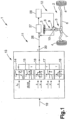
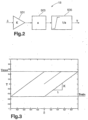
- Figures 2-3 show in more detail an example of the friction model 16,18.
- the value of the steering wheel angle ⁇ is input to a first box 501 representing a stiffness K, which corresponds to a lumped spring stiffness in Nm/Rad.
- the resulting value from the first box 501 is input to a second box 503 representing a derivative as indicated by the Laplace operator s.
- the derived steering wheel angle signal i.e. the steering wheel angle speed multiplied with the stiffness K is passed into a third box 505 representing an integrating function with anti windup functionality, indicated through the integrational limits and the inverse of the laplace transformator.
- the limit values are chosen in order to limit the frictional torque to the desired maximum and minimum values.
- the mentioned anti-windup functionality is intended to cease integration once the integrational limits are reached.
- the relationship between the steering wheel angle ⁇ and the output torque value is shown in figure 6.
- the steering characteristic model(s) 14,15,16,17,18 is preferably designed so that a different steering characteristic parameter takes precedence over the others in different driving scenarios.
- the lateral acceleration is configured to take precedence over the other steering characteristic parameters during driving in high speed.
- steering system friction and tire friction are configured to take precedence over the other steering characteristic parameters during driving in low speed.
- the damping torque is equally active regardless of vehicle speed.
- the self alignment is configured to take precedence over the other steering characteristic parameters during driving in an intermediate speed interval between the high speed and the low speed.
- the present invention concerns a method for assisting the driver of the vehicle during operation.
- the control method is configured to allow a control of the steering characteristics experienced by a driver of the vehicle during traveling.
- the control method is configured to provide the operator with a steering feel (or steering sensitivity or tactile feedback) through the steering wheel.
- the method comprises the step of determining the desired resistance torque based on an input representing a steering angle.
- the steering angle is preferably determined by measuring a steering wheel deflection.
- the steering angle may be determined by measuring a wheel angle or anywhere inbetween the steering wheel and the ground engaging wheel in the mechanical steering arrangement.
- the reference generator 13 and the regulating loop 12 are preferably implemented in software.
- a value of the vehicle lateral acceleration may be estimated from a measured vehicle yaw rate.
Landscapes
- Engineering & Computer Science (AREA)
- Chemical & Material Sciences (AREA)
- Combustion & Propulsion (AREA)
- Transportation (AREA)
- Mechanical Engineering (AREA)
- Steering Control In Accordance With Driving Conditions (AREA)
- Power Steering Mechanism (AREA)
Description
- The present invention relates to a method and a system for assisting a driver of a vehicle during operation by providing the driver with a desired steering feel.
- It is known to provide the driver with a desired steering feel by applying a guiding force to the steering device based on different input parameters, such as steering device deflection, lateral acceleration, yaw rate and vehicle speed.
- The guiding force exerted onto the steering device is resistive if counteracting the force applied by the driver onto the steering device, or supportive if acting in the same direction as the force applied by the driver onto the steering device, thus for instance reducing the effect of e.g. frictional forces acting on the wheels and the like which are experienced by the driver as resistance when operating the steering device.
- The steering device is normally formed by a conventional steering wheel in the case of a vehicle. However, the invention is applicable to other steering devices, such as a joystick, a sliding nipple or any other suitable steering device for steering the vehicle. For instance, in the case that the steering device is a steering wheel, the guiding force will appear as a guiding torque exerted onto the steering wheel. Thus, in this case, the term steering feel denotes the steering wheel torque experienced by the driver during operation of the vehicle.
-
EP 1431160 discloses a system for estimating a steering wheel resist torque based on steering wheel rotation angle, vehicle speed and lateral acceleration or yaw rate. The steering wheel is connected to the road wheels via a steering shaft arrangement and the delivered steering wheel resist torque is measured and compared with the estimated steering wheel resist torque, whereupon the delivered steering wheel resist torque is adapted by use of a feedback controller to be substantially the same as the estimated steering wheel resist torque. It has turned out that this system in certain operations may be regarded as unsteady. Further, it has turned out that the steering feel is reduced when driving in long curves. - In
EP1977953 A1 , which is considered as the closest prior art, a steered shaft of a steered mechanism is rigidly fixed to a vehicle body. Steering-stiffness is reduced by a lowpass filter for filtering a steered angle detected by a steered angle sensor. A deviation between a target steered angle and the filtered steered angle detected by the steered angle sensor is input to a PID control unit. A gain setting unit sets each of gains for PID control at a low value to thereby reduce steering-stiffness. The PID control unit outputs a target current. A drive circuit performs, e.g., PID control of the steering actuator. -
US2006/086560 A1 discloses a vehicle steering apparatus which is comprised of an assist motor, a steering torque sensor, a steering angle sensor, and a controller. The controller has a torque producing section for estimating a virtual steering model input torque from a torque sensor detection value and a steering angle detection value, a virtual steering model of representing a desired steering characteristic which receives the virtual steering model input torque and outputs a target steering angle of a steering column shaft, and a steering angle servo for controlling an output of the assist motor so that the steering angle detection angle follows the target steering angle. -
US 2008/087491 A1 discloses a steering system for a vehicle has a steering wheel that is mechanically connected to the steerable vehicle wheels via a steering column. An actuating device is actuated by a control device to generate an actuating device holding torque that acts in the steering column. The actuating device has two friction elements that can be placed in frictional contact. The actuating device holding torque is variable and depends on the friction force generated between the two friction elements. The reaction torque that acts on the steering wheel when there is steering intervention which is independent of the driver can be reduced or compensated by the actuating device holding torque. - One object of the invention is to achieve a method for assisting a driver which creates conditions for an improved steering feel.
- This object is achieved by the method defined in
claim 1. - The invention is based on the insight that a certain friction feel is desired, see further below. Preferably, the desired steering device guiding force represents a nominal, desired friction. Said term "steering arrangement" may be a nominal steering arrangement.
- The determined desired steering device guiding force can be based on further information, such as further desired steering characteristics in addition to the friction component. Thus, the determined desired steering device guiding force may be a sum of desired forces (such as torque components).
- Preferably, the vehicle comprises an actual steering arrangement comprising a manual steering device, at least one pair of ground engaging members and a mechanical connection between the manual steering device and said ground engaging members.
- According to the present invention, the method comprises the step of providing the driver with the desired steering feel by applying a final steering device guiding force based on the desired steering device guiding force to a manually operated steering device. Said manually operated steering device is preferably formed by a steering wheel. The term "final" with regard to the steering device guiding force defines in this case that the actively supplied steering device guiding force does not necessarily equal the determined desired steering device guiding force. The method comprises the step of determining an actual force to the steering device resulting from an actual vehicle steering arrangement during operation, and determining a value of a final steering device guiding force to be applied to the steering device by subtracting a value of the determined actual force from a value of the determined desired steering device guiding force.
- Preferably, the actual force is formed by an actual torque to the steering wheel, which is determined via an elastic element, such as a torsion bar, in the steering arrangement.
- Preferably, a steering torque is determined by measuring the twist of the torsion bar in the steering arrangement. More precisely, a first angular sensor is arranged at a first end of the torsion bar and a second angular sensor is arranged at a second end of the torsion bar (opposite the first end). The steering torque can be determined based on the relative angular movement (twist) of the torsion bar and the stiffness of the torsion bar. According to an alternative, one or several strain gauges may be used.
- According to an example embodiment, the method comprises the step of at least suppressing a driver steering feel from the influence of friction in a steering arrangement in the vehicle, which is configured to steer at least one ground engaging member.
- The suppression of the driver steering feel from the influence of friction in the steering arrangement is preferably accomplished via a so-called reference generator function or any other known means of friction compensation device or function.
- The suppression of the driver steering feel from the influence of friction in the steering arrangement is preferably accomplished simultaneously as the application of the steering device guiding force. Preferably a driver steering feel is decoupled from the influence of friction in the steering arrangement. Thus, the influence of friction in the steering arrangement is preferably completely removed.
- This embodiment creates conditions for using an Electrical Power Assisted Steering (EPAS) system. Especially, the method is applicable in steering systems where there is a mechanical connection between the steering device and the ground but where the inherent steering feel resulting from the mechanical connection during operation is eliminated or at least suppressed.
- For example, the inherent mechanical friction in the actual steering arrangement depends on different operational conditions, such as manufacturing tolerances, wear, temperature, age etc. Thus, the mechanical friction in the mechanical connection is different for different individual vehicles and varies over time. Thus, this embodiment creates conditions for decoupling the hardware (mechanical connection) from the friction steering feel. In other words, the embodiment creates conditions for an application-independent (hardware-independent) friction steering feel.
- Preferably, the method comprises the step of determining a desired steering device guiding force based on a vehicle state, such as a steering angle. The steering angle is preferably defined by a steering wheel deflection.
- Preferably, the method comprises the step of applying the determined steering device guiding force to the steering arrangement and simultaneously at least suppressing steering device disturbances resulting from the mechanical interconnection.
- According to the invention, a delivered steering device guiding force is measured and compared with an estimated desired steering device guiding force, wherein the delivered steering device guiding force is adapted by use of a feedback controller to be substantially the same as the desired steering device guiding force through adapting the amount of said guiding force.
- According to a further example embodiment, the method comprises the step of determining the steering device guiding force by means of at least one predetermined friction model of the desired friction in the vehicle steering arrangement. According to the invention, the method comprises the step of applying the steering device guiding force to the steering arrangement by means of an actuator.
- According to a further example embodiment, the friction model represents the friction between a flexible element and the steering device in the steering arrangement, wherein the flexible element is configured for a relative displacement in a circumferential direction about a steering axis, which displacement is generated between an upper and a lower shaft of the steering arrangement. This embodiment is based on the insight that this specifically defined friction is advantageous for the steering feel.
- The displacement in the circumferential direction is generated between the upper and the lower shaft of the according to turn of the steering wheel with twist of the flexible element (torsion bar) interposed between the upper and lower shafts.
- Friction in the upper steering column is desired due to the fact that:
- friction dissipates energy and thus adds damping (in a non-linear manner) to the system,
- a certain amount of friction reduces the drivers torque in long curves, the driver can so to say "rest his/her arms in friction", and
- a steering system without friction is experienced as a pure spring.
- According to a further example embodiment, the friction model is configured to not represent the friction between an actuator for applying the steering device guiding force to the steering device and the flexible element in the steering arrangement, but rather represent the desired amount of friction between steering wheel and the flexible device. This embodiment is based on the insight that only this specifically defined friction is advantageous for the steering feel. Thus, friction in an electric power assisted steering system is distuingished into two separate categories, namely:
- friction above the torsion bar, which (to a certain degree) is desired, and
- friction between the electric actuator and the torsion bar, which is undesired from a control and stability point of view.
- A further object of the invention is to achieve a system for assisting a driver which creates conditions for an improved steering feel.
- This object is achieved by the system defined in
claim 9. Thus, it is achieved by a system for assisting a driver of a vehicle during operation by providing the driver with a desired steering feel, characterized by a means for determining a desired steering device guiding force comprising a part representing a desired friction in a steering arrangement, and means for providing the driver with the desired steering feel based on the determined steering device guiding force by applying a final steering device guiding force based on the desired steering device guiding force to a manually operated steering device. The system further comprises means for determining an actual force to the steering device resulting from an actual vehicle steering arrangement during operation, and means for determining a value of a final steering device guiding force to be applied to the steering device by subtracting a value of the determined actual force from a value of the determined desired steering device guiding force. - According to an example embodiment, the system comprises a means for suppressing a driver steering feel from the influence of friction in a steering arrangement in the vehicle, which is configured to steer at least one ground engaging member.
- According to a further example embodiment, said means for determining a desired steering device guiding force comprises at least one predetermined friction model of the desired friction in the vehicle steering arrangement.
- According to a further example embodiment, the friction model represents the friction between a flexible element and the steering device in the steering arrangement, wherein the flexible element is configured for a relative displacement in a circumferential direction about a steering axis, which displacement is generated between an upper and a lower shaft of the steering arrangement.
- Further example embodiments and advantages thereof emerge from the description below, the figures and the claims.
- The invention will be described in greater detail below with reference to the embodiment shown in the accompanying drawings, in which
- FIG 1
- schematically shows a system for performing the inventive method according to one embodiment,
- FIG 2-3
- shows an embodiment for a friction model.
- The invention is below described for application in a truck. However, the invention should not be regarded as limited to trucks, but it may be applied also in other vehicles, such as cars.
Fig 1 schematically shows asystem 1 for performing a control method according to one embodiment. Thesystem 1 comprises amechanical steering arrangement 2, which may be of a conventional type. Themechanical steering arrangement 2 comprises a steering device 3 in the form of a steering wheel, at least one ground engagement member 4 in the form of a wheel and amechanical connection 5 between the steering wheel 3 and the wheels 4 for transmission of steering signals from the steering wheel 3 to the wheels 4. - The steering wheel 3 is arranged in a vehicle passenger compartment and manually operated by the driver of the vehicle to steer the wheels 4. The
steering arrangement 2 comprises a steering linkage means 6 extending from the steering wheel 3 down to a Hydraulic Power Assisted System (HPAS) 7 for converting angular rotation in thesteering linkage 6 to a linear movement via asteering member 8. The steering linkage means 6 comprises an electric steering gear. The HPAS may be of conventional type comprising a hydraulic cylinder (not shown) and a torsion bar (not shown). The steeringmember 8 is coupled on opposite ends to a left and right wheel 4 and configured to turn the wheels 4 in response to steering signals from the steering wheel 3. - The
system 1 further comprises anactuator 9 to provide supported adjustment of the steering angle. Theactuator 9 is preferably formed by an electric motor. - The
actuator 9 provides a guiding force, and more specifically a guiding torque, or assist torque, to the steering assembly for assisting the driver in steering the steering wheel. The electric motor may be arranged around a steering column in thesteering arrangement 2, wherein the magnetic field acts directly on the steering column. Alternatively, the electric motor may be arranged beside the steering column and act on the steering column via a mechanical linkage, preferably via pinion gears. - The
system 1 further comprises a torque-measuring device, or sensor, 10 for measuring a manual torque applied by the driver to the steering wheel. The torque-measuringdevice 10 is of elastic constitution and preferably comprises a torsion bar. In other words, a steering wheel angle is measured via the torsion bar. More specifically, the electric steering gear comprises said torsion bar. In other words, thetorque sensor 10 detects, as the steering torque applied to the steering wheel, a relative displacement in a circumferential direction which is generated between the upper and lower shafts of the steering shaft turning about the axis of the steering wheel according to turn of the steering wheel with twist of the torsion bar interposed between the upper and lower shafts. - The
system 1 further comprises an Electrical Power Assisted Steering (EPAS)system 11. TheEPAS 11 comprises a regulatingloop 12, which is configured to achieve a torque-free steering. The regulatingloop 12 is configured to receive an input signal indicative of a current steering torque in the steering wheel 3. The input signal is received from the torque-measuringdevice 10. Basically, the regulatingloop 12 is configured to output a signal to theactuator 9 so that said torque free steering is achieved. - The regulating
loop 12 comprises a controller, or regulator, 27 which comprises a filter function. The filter function may be based on an inverse model of the steering dynamics of the present vehicle. Further, theregulator 27 may be configured to reduce errors in the model and to reduce disturbances and measurement noise in order to reduce the risk of instability in the system. - The
regulator 27 is configured to receive a signal indicative of a torque to be applied to the steering arrangement via the electric motor and in response thereto produce an output signal. The regulatingloop 12 further comprises an electric motor control means 28, which is configured to receive the output signal indicative of a torque from theregulator 27 and produce a signal with a corresponding current value to the electric motor. According to an alternative, theregulator 27 and the electric motor control means 28 are combined in a single controller. - The EPAS further comprises a controlling
function 13, below referred to as a reference generator, which is configured to determine a desired torque to be applied to the steering wheel in order to provide the driver with a desired steering feel. In other words, the reference generator describes a nominal vehicle. - Further, the
reference generator 13 is operatively connected to the regulatingloop 12 and outputs a signal indicative of a desired steering torque. The regulating loop is configured to compare the desired steering torque to the actual, current steering torque and continuously adapt the output signal to the actuator so that the desired steering torque is transmitted to the driver. In other words, the actuator is controlled so that it applies the difference in torque between the desired torque value from the reference generator and the current actual torque in the steering assembly so that the actual torque is controlled to substantially equal the desired torque. - The
reference generator 13 comprises at least one steering device guiding force operation model and in the example infigure 1 a plurality of guidingforce operation models - Further, the model (s) comprises at least one desired steering characteristic parameter. More specifically, each model is configured to produce a guiding torque value T for one desired and predetermined steering characteristic parameter based on at least one
input 19. In other words, the steering characteristic parameter is a guiding force influencing operational parameter. Each model comprises a mathematical function, wherein the torque value is determined as a function of a value of the input, see illustrated examples of the functions infigure 1 . - The individual torque values resulting from the models are summed up to a torque sum, which forms an
output 20 from the reference generator. According to the shown embodiment, the reference generator comprises models for the following steering characteristic parameters: vehicle lateral acceleration, damping of steering device movements, tire friction, self alignment of the steering device to a neutral position and friction in the mechanical connection between the steering device and the wheels. - The signals input to the reference generator comprises a at least one signal indicative of a steering intent of the driver, such as a steering wheel angle (δ) and a rate of change of the steering wheel angle (d5/dt). According to an alternative to the steering wheel angle, the signal indicative of a steering intent may be an electric motor angle or a wheel angle. According to an alternative to the rate of change of the steering wheel angle, the signal indicative of a steering intent may be a rate of change of the electric motor angle or a rate of change of the wheel angle.
- The signals input to the reference generator comprises at least one signal indicative of a vehicle body motion, such as lateral acceleration (Ay) and/or yaw rate. Such a vehicle body motion may be sensed by a sensor arranged in the vehicle.
- The vehicle
lateral acceleration model 14 represents a predetermined relationship between a guiding torque value and the current lateral acceleration for achieving a desired steering feel. Thus, themodel 14 receives a signal indicative of a current lateral acceleration as an input signal. According to the example function shown infigure 1 , the torque value increases dramatically for small input values of the lateral acceleration. Further, the torque value increases substantially less for larger input values of the lateral acceleration. In other words, the curve flattens out. The vehiclelateral acceleration model 14 is preferably a pure statical mapping. According to a preferred example, the vehicle lateral acceleration is the most important steering characteristic parameter. - The damping
model 15 represents a predetermined relationship between a guiding torque value and the current steering wheel speed for achieving a desired steering feel. Thus, the dampingmodel 15 preferably receives a signal indicative of a steering wheel speed (rate of change of the steering wheel position). According to the example function shown infigure 1 , the torque value increases dramatically for small input values of the steering wheel speed. Further, the torque value increases substantially less for larger input values of the steering wheel speed. In other words, the curve flattens out. The dampingmodel 15 is preferably a pure statical mapping. The torque value output from the damping model is configured to act in an opposite direction with regard to the current steering wheel speed. The damping model is preferably designed so that the resulting torque is smaller for higher steering wheel speeds and higher for smaller steering wheel speeds. In this way, the damping torque is proportional to the steering wheel angle speed during normal driving and limited to a maximum value during parking or evasive manouevres. - Thus, the vehicle
lateral acceleration model 14 and the dampingmodel 15 are linked to each other. - The
self alignment model 17 represents a predetermined relationship between a guiding torque value and the current steering wheel angle for achieving a desired steering feel. By self alignment of the steering device to a neutral position is meant an active return, i.e. the return of the released steering wheel to a central setting. Theself alignment model 17 preferably receives a signal indicative of the steering wheel angle and a signal indicative of vehicle speed as input signals. The purpose of the vehicle speed input signal is to be able to modulate the desired aligning torque with the current vehicle speed in a way that the self alignment torque can be reduced during high speed driving. - Regarding the
friction models - The
tire model 16 comprises a hysteresis curve, which represents a tire model. Preferably, themodel 16 is a dynamic model of an unrolling tire with regard to steering torque. The relation between the steering wheel angle and the torque is given by a physical relationship, where the deflection of individual rubber elements is modeled dependent on the differential angle of the steering wheel and the torsion and relaxation of the rubber elements due to the rolling tire. The resulting model yields thus a smaller hysteresis effect with increasing vehicle speed and constant steering wheel angle frequency. - The inventive method creates conditions for canceling the actual friction effect in the steering wheel resulting from the actual steering arrangement and instead applying a desired resistance torque to the steering wheel, which represents a nominal friction feel for the driver. Thus, the hardware (mechanical steering arrangement) is decoupled from the friction steering feel. In other words, the invention creates conditions an application-independent (hardware-independent) friction steering feel.
- The
tire friction model 16 and the mechanicalconnection friction model 18 are in principle similar to each other. Thetire friction model 16 represents the friction between the tire and the ground while the mechanicalconnection friction model 18 represents the friction in the upper steering wheel steering column assembly. Thus, a lumped frictional stiffness in the mechanicalconnection friction model 18 is higher than in thetire friction model 16. Thetire friction model 16 preferably receives a signal indicative of a steering wheel angle and a signal indicative of vehicle speed. The mechanicalconnection friction model 18 preferably receives a signal indicative of a steering wheel angle. -
Figures 2-3 show in more detail an example of thefriction model first box 501 representing a stiffness K, which corresponds to a lumped spring stiffness in Nm/Rad. The resulting value from thefirst box 501 is input to asecond box 503 representing a derivative as indicated by the Laplace operator s. The derived steering wheel angle signal, i.e. the steering wheel angle speed multiplied with the stiffness K is passed into athird box 505 representing an integrating function with anti windup functionality, indicated through the integrational limits and the inverse of the laplace transformator. The limit values are chosen in order to limit the frictional torque to the desired maximum and minimum values. The mentioned anti-windup functionality is intended to cease integration once the integrational limits are reached. The relationship between the steering wheel angle δ and the output torque value is shown in figure 6. - The steering characteristic model(s) 14,15,16,17,18 is preferably designed so that a different steering characteristic parameter takes precedence over the others in different driving scenarios. According to one example, the lateral acceleration is configured to take precedence over the other steering characteristic parameters during driving in high speed. According to a further example, steering system friction and tire friction are configured to take precedence over the other steering characteristic parameters during driving in low speed. The damping torque is equally active regardless of vehicle speed. According to a further example, the self alignment is configured to take precedence over the other steering characteristic parameters during driving in an intermediate speed interval between the high speed and the low speed.
- The present invention concerns a method for assisting the driver of the vehicle during operation. According to a preferred embodiment, the control method is configured to allow a control of the steering characteristics experienced by a driver of the vehicle during traveling. In other words, the control method is configured to provide the operator with a steering feel (or steering sensitivity or tactile feedback) through the steering wheel.
- With regard to friction feel, according to an example embodiment, the method comprises the step of determining the desired resistance torque based on an input representing a steering angle. By determining a direction of the actual steering angle (clockwise or counterclockwise) and instantly applying a torque in the same direction, the effect of the friction in the steering arrangement can be effectively cancelled.
- The steering angle is preferably determined by measuring a steering wheel deflection. Alternatively, the steering angle may be determined by measuring a wheel angle or anywhere inbetween the steering wheel and the ground engaging wheel in the mechanical steering arrangement.
- The
reference generator 13 and the regulating loop 12 (comprising thecontrollers 27,28) are preferably implemented in software. - A value of the vehicle lateral acceleration may be estimated from a measured vehicle yaw rate.
Claims (15)
- A method for assisting a driver of a vehicle during operation by providing the driver with a desired steering feel in a mechanical steering arrangement, where the mechanical steering arrangement comprises a steering device, at least one ground engagement member and a mechanical connection between the steering device and the at least one ground engagement member, said method being performed by a system (1) comprising said mechanical steering arrangement, an actuator (9), a torque-measuring device (10), and an electrical power assisted steering system (11) which in turn comprises a regulating loop (12) and a reference generator (13) operatively connected to said regulating loop (12), characterized by the steps of- determining a desired steering device guiding torque comprising a part representing a desired friction in a steering arrangement, where the desired steering device guiding torque is determined by means of at least one predetermined friction model, forming part of said reference generator (13), of the desired friction in the vehicle steering arrangement, and where the desired steering device guiding torque is determined based on an input signal indicative of a steering intent of a driver and on an input signal indicative of a vehicle body movement,- providing the driver with the desired steering feel based on the determined steering device guiding torque- providing the driver with the desired steering feel by applying a final steering device guiding torque based on the desired steering device guiding torque to a manually operated steering device using said actuator (9)- determining an actual torque to the steering device resulting from an actual vehicle steering arrangement during operation using said torque-measuring device (10), and- determining a value of a final steering device guiding torque to be applied to the steering device by subtracting a value of the determined actual torque from a value of the determined desired steering device guiding torque using said regulating loop (12).
- A method according to any preceding claim, characterized by at least suppressing a driver steering feel from the influence of friction in a steering arrangement in the vehicle, which is configured to steer at least one ground engaging member.
- A method according to any preceding claim, where the input signal indicative of a vehicle body movement comprises a lateral acceleration signal and/or a yaw rate signal.
- A method according to any preceding claim, where the input signal indicative of a steering intent of a driver comprises a steering wheel angle signal and/or a rate of change signal of the steering wheel angle.
- A method according to any preceding claim, characterized by that the friction model represents the friction between a flexible element and the steering device in the steering arrangement, wherein the flexible element is configured for a relative displacement in a circumferential direction about a steering axis, which displacement is generated between an upper and a lower shaft of the steering arrangement.
- A method according to claim 5, characterized by that the friction model is configured to not represent the friction between an actuator for applying the steering device guiding torque to the steering device and the flexible element in the steering arrangement.
- A method according to claim 5, characterized by that the flexible element forms a torsion bar.
- A method according to claim 1, wherein the steering device is a steering wheel, and wherein the at least one ground engagement member is at least one wheel.
- A system for assisting a driver of a vehicle during operation by providing the driver with a desired steering feel in a mechanical steering arrangement, where the mechanical steering arrangement comprises a steering device (3), at least one ground engagement member (4) and a mechanical connection (5) between the steering device (3) and the at least one ground engagement member (4), characterized bya means (13) for determining a desired steering device guiding force comprising a part representing a desired friction in a steering arrangement, where said means (13) for determining a desired steering device guiding force comprises at least one predetermined friction model (18) of the desired friction in the vehicle steering arrangement and at least one predetermined vehicle lateral acceleration model (14),means (9) for providing the driver with the desired steering feel based on the determined steering device guiding force by applying a final steering device guiding force based on the desired steering device guiding force to a manually operated steering device,means (10) for determining an actual force to the steering device resulting from an actual vehicle steering arrangement during operation, andmeans (12) for determining a value of a final steering device guiding force to be applied to the steering device by subtracting a value of the determined actual force from a value of the determined desired steering device guiding force.
- A system according to claim 9, characterized by a means (12) for suppressing a driver steering feel from the influence of friction in a steering arrangement (2) in the vehicle, which is configured to steer at least one ground engaging member (4).
- A system according to claim 10, characterized by that the friction model represents the friction between a flexible element (10) and the steering device (3) in the steering arrangement (2), wherein the flexible element is configured for a relative displacement in a circumferential direction about a steering axis, which displacement is generated between an upper and a lower shaft of the steering arrangement.
- A system according to any of claims 9 to 11, wherein the means (13) for determining a desired steering device guiding force comprises a controller and the means (9) for providing the driver with the desired steering feel comprises an actuator.
- A system according to any of claims 10 to 12, wherein the means (12) for suppressing a driver steering feel comprises a feedback loop.
- A system according to any of claims 9 to 13, where said means (13) for determining a desired steering device guiding force is provided with at least one input (19) for a signal indicative of a steering intent of a driver and for a signal indicative of a vehicle body movement.
- A system according to claim 9, wherein the steering device is a steering wheel, and wherein the at least one ground engagement member is at least one wheel.
Priority Applications (1)
| Application Number | Priority Date | Filing Date | Title |
|---|---|---|---|
| EP14020091.6A EP2857286B2 (en) | 2009-06-29 | 2009-06-29 | A method and a system for assisting a driver of a vehicle during operation |
Applications Claiming Priority (3)
| Application Number | Priority Date | Filing Date | Title |
|---|---|---|---|
| EP09846894.5A EP2448806B1 (en) | 2009-06-29 | 2009-06-29 | A method and a system for assisting a driver of a vehicle during operation |
| EP14020091.6A EP2857286B2 (en) | 2009-06-29 | 2009-06-29 | A method and a system for assisting a driver of a vehicle during operation |
| PCT/SE2009/000338 WO2011002347A1 (en) | 2009-06-29 | 2009-06-29 | A method and a system for assisting a driver of a vehicle during operation |
Related Parent Applications (2)
| Application Number | Title | Priority Date | Filing Date |
|---|---|---|---|
| EP09846894.5A Division EP2448806B1 (en) | 2009-06-29 | 2009-06-29 | A method and a system for assisting a driver of a vehicle during operation |
| EP09846894.5A Division-Into EP2448806B1 (en) | 2009-06-29 | 2009-06-29 | A method and a system for assisting a driver of a vehicle during operation |
Publications (4)
| Publication Number | Publication Date |
|---|---|
| EP2857286A2 EP2857286A2 (en) | 2015-04-08 |
| EP2857286A3 EP2857286A3 (en) | 2015-05-06 |
| EP2857286B1 EP2857286B1 (en) | 2017-12-13 |
| EP2857286B2 true EP2857286B2 (en) | 2024-10-16 |
Family
ID=43411240
Family Applications (2)
| Application Number | Title | Priority Date | Filing Date |
|---|---|---|---|
| EP09846894.5A Active EP2448806B1 (en) | 2009-06-29 | 2009-06-29 | A method and a system for assisting a driver of a vehicle during operation |
| EP14020091.6A Active EP2857286B2 (en) | 2009-06-29 | 2009-06-29 | A method and a system for assisting a driver of a vehicle during operation |
Family Applications Before (1)
| Application Number | Title | Priority Date | Filing Date |
|---|---|---|---|
| EP09846894.5A Active EP2448806B1 (en) | 2009-06-29 | 2009-06-29 | A method and a system for assisting a driver of a vehicle during operation |
Country Status (6)
| Country | Link |
|---|---|
| US (1) | US9751557B2 (en) |
| EP (2) | EP2448806B1 (en) |
| JP (1) | JP5976536B2 (en) |
| CN (1) | CN102648119B (en) |
| BR (1) | BRPI0925076B1 (en) |
| WO (1) | WO2011002347A1 (en) |
Families Citing this family (18)
| Publication number | Priority date | Publication date | Assignee | Title |
|---|---|---|---|---|
| EP2448806B1 (en) | 2009-06-29 | 2015-04-22 | Volvo Lastvagnar AB | A method and a system for assisting a driver of a vehicle during operation |
| US8489282B2 (en) * | 2011-02-16 | 2013-07-16 | Steering Solutions Ip Holding Corporation | Electric power steering control methods and systems |
| ITTO20110795A1 (en) | 2011-09-07 | 2013-03-08 | Cnh Italia Spa | STEERABLE VEHICLE |
| GB201118620D0 (en) * | 2011-10-27 | 2011-12-07 | Jaguar Cars | Improvements in closed loop EPAS system |
| KR101783075B1 (en) * | 2013-05-28 | 2017-10-23 | 주식회사 만도 | Method and apparatus for steering control due to the failure of motor position sensor |
| FR3018917B1 (en) * | 2014-03-18 | 2016-04-01 | Jtekt Europe Sas | MODELING FRICTION IN A DIRECTION ASSISTED BY A CLOUD OF POINTS |
| DE102014206465A1 (en) | 2014-04-03 | 2015-10-08 | Volkswagen Aktiengesellschaft | Control device for an electromechanical power steering |
| DE102017200600B3 (en) | 2017-01-17 | 2018-07-19 | Ford Global Technologies, Llc | Method and device for assisting a driver of a motor vehicle during vehicle operation |
| EP3360757B1 (en) * | 2017-02-10 | 2019-10-02 | Volvo Car Corporation | Steer torque manager for an advanced driver assistance system of a road vehicle |
| EP3375696B1 (en) | 2017-03-17 | 2019-11-20 | Volvo Car Corporation | Steer torque manager for an advanced driver assistance system of a road vehicle |
| EP3378733B1 (en) | 2017-03-20 | 2020-01-15 | Volvo Car Corporation | Apparatus and method for situation dependent wheel angle control (had or adas) |
| EP3378731B1 (en) | 2017-03-20 | 2020-01-15 | Volvo Car Corporation | Apparatus and method for driver activity dependent (adas) wheel angle controller |
| US11603128B2 (en) * | 2018-08-08 | 2023-03-14 | Nissan Motor Co., Ltd. | Steering control method and steering control device |
| JP2020069863A (en) * | 2018-10-30 | 2020-05-07 | 株式会社ジェイテクト | Steering control device |
| JP7180334B2 (en) * | 2018-12-04 | 2022-11-30 | トヨタ自動車株式会社 | Steering system, steering support device |
| DE102019206980B4 (en) * | 2019-05-14 | 2023-06-22 | Volkswagen Aktiengesellschaft | Method and steering control device for determining a manipulated variable for setting a power steering torque in a vehicle steering system |
| WO2022208680A1 (en) * | 2021-03-30 | 2022-10-06 | Honda Motor Co., Ltd. | Steering system for vehicle |
| KR20230080553A (en) * | 2021-11-30 | 2023-06-07 | 현대자동차주식회사 | Steering repulsive power control apparatus of steer-by-wire system |
Citations (6)
| Publication number | Priority date | Publication date | Assignee | Title |
|---|---|---|---|---|
| US5473539A (en) † | 1992-12-11 | 1995-12-05 | Honda Giken Kogyo Kabushiki Kaisha | Electrically operated power steering apparatus |
| US5719766A (en) † | 1995-10-02 | 1998-02-17 | General Motors Corporation | Electric power steering control |
| US20050072621A1 (en) † | 2003-10-02 | 2005-04-07 | Nissan Motor Co., Ltd. | Vehicle steering apparatus |
| JP2008197899A (en) † | 2007-02-13 | 2008-08-28 | Nsk Ltd | Electric power steering system design system and electric power steering system |
| JP2008307910A (en) † | 2007-06-12 | 2008-12-25 | Nsk Ltd | Control device for electric power steering device |
| US20100027364A1 (en) † | 2005-09-29 | 2010-02-04 | Jae-Hyuk Im | Multi-port memory device having self-refresh mode |
Family Cites Families (27)
| Publication number | Priority date | Publication date | Assignee | Title |
|---|---|---|---|---|
| US3580352A (en) * | 1969-01-21 | 1971-05-25 | Gen Motors Corp | Steering torque servo |
| DE1955308C3 (en) * | 1969-11-04 | 1978-05-24 | Raoul Dipl.-Ing. 8992 Hengnau Joern | Rubber-metal articulated bush |
| DE2746919A1 (en) * | 1977-10-19 | 1979-04-26 | Zahnradfabrik Friedrichshafen | POWER STEERING DEVICE FOR VEHICLES |
| JP2612743B2 (en) * | 1988-04-30 | 1997-05-21 | 自動車機器株式会社 | Control method of electric power steering device |
| JPH10310069A (en) * | 1997-05-12 | 1998-11-24 | Honda Motor Co Ltd | Cable steering system |
| JP3698613B2 (en) | 2000-03-28 | 2005-09-21 | 光洋精工株式会社 | Electric power steering device |
| US7219761B2 (en) * | 2000-07-21 | 2007-05-22 | Nsk Ltd. | Motor-operated power steering apparatus |
| JP2002166844A (en) * | 2000-12-01 | 2002-06-11 | Toyoda Mach Works Ltd | Control device for electric power steering device |
| GB2372020A (en) * | 2001-02-07 | 2002-08-14 | Lucas Industries Ltd | Haptic controller for electrically-assisted power steering in road vehicles |
| DE60204160D1 (en) | 2001-10-10 | 2005-06-16 | Reginald Frederick Taylor | IMLOCHBOHRHAMMER |
| US6678595B2 (en) * | 2002-03-29 | 2004-01-13 | Visteon Global Technologies, Inc. | System and method of simulating a steering resistance torque on a vehicle steering wheel |
| US7233850B2 (en) * | 2002-10-31 | 2007-06-19 | Koyo Seiko Co., Ltd. | Vehicle steering apparatus |
| DE60213436T2 (en) | 2002-12-20 | 2007-03-01 | Ford Global Technologies, LLC, Dearborn | Control strategy for computer-controlled steering |
| US6863150B1 (en) * | 2003-09-25 | 2005-03-08 | Mitsubishi Denki Kabushiki Kaisha | Electric power steering control apparatus |
| DE102004025554A1 (en) | 2004-04-14 | 2005-11-03 | Daimlerchrysler Ag | steering system |
| JP4078336B2 (en) * | 2004-06-24 | 2008-04-23 | 本田技研工業株式会社 | Electric steering device |
| BRPI0513156B1 (en) * | 2004-08-06 | 2017-12-26 | Honda Motor Co., Ltd. | DEVICE CONTROL FOR A VEHICLE EQUIPPED WITH A VARIABLE OUTPUT DEVICE MANIPULATED TO DRIVE ?? |
| JP4779495B2 (en) * | 2004-10-27 | 2011-09-28 | 日産自動車株式会社 | Vehicle steering system |
| US7546191B2 (en) * | 2004-12-20 | 2009-06-09 | General Motors Corporation | Handwheel damping control of active steering system |
| JP2007168756A (en) | 2005-12-26 | 2007-07-05 | Showa Corp | Electric power steering device |
| JP4419997B2 (en) * | 2006-08-28 | 2010-02-24 | トヨタ自動車株式会社 | Electric power steering device |
| JP4380697B2 (en) * | 2006-12-28 | 2009-12-09 | 日産自動車株式会社 | Vehicle steering control device |
| JP5003228B2 (en) | 2007-03-23 | 2012-08-15 | トヨタ自動車株式会社 | Electric power steering device |
| JP5003944B2 (en) | 2007-04-02 | 2012-08-22 | 株式会社ジェイテクト | Vehicle steering system |
| KR100867698B1 (en) * | 2007-07-18 | 2008-11-10 | 현대자동차주식회사 | Steer-by-wire system of the car |
| JP5231793B2 (en) * | 2007-12-10 | 2013-07-10 | トヨタ自動車株式会社 | Steering device |
| EP2448806B1 (en) | 2009-06-29 | 2015-04-22 | Volvo Lastvagnar AB | A method and a system for assisting a driver of a vehicle during operation |
-
2009
- 2009-06-29 EP EP09846894.5A patent/EP2448806B1/en active Active
- 2009-06-29 US US13/381,227 patent/US9751557B2/en active Active
- 2009-06-29 CN CN200980160197.2A patent/CN102648119B/en not_active Expired - Fee Related
- 2009-06-29 BR BRPI0925076A patent/BRPI0925076B1/en active IP Right Grant
- 2009-06-29 EP EP14020091.6A patent/EP2857286B2/en active Active
- 2009-06-29 WO PCT/SE2009/000338 patent/WO2011002347A1/en not_active Ceased
- 2009-06-29 JP JP2012518506A patent/JP5976536B2/en not_active Expired - Fee Related
Patent Citations (6)
| Publication number | Priority date | Publication date | Assignee | Title |
|---|---|---|---|---|
| US5473539A (en) † | 1992-12-11 | 1995-12-05 | Honda Giken Kogyo Kabushiki Kaisha | Electrically operated power steering apparatus |
| US5719766A (en) † | 1995-10-02 | 1998-02-17 | General Motors Corporation | Electric power steering control |
| US20050072621A1 (en) † | 2003-10-02 | 2005-04-07 | Nissan Motor Co., Ltd. | Vehicle steering apparatus |
| US20100027364A1 (en) † | 2005-09-29 | 2010-02-04 | Jae-Hyuk Im | Multi-port memory device having self-refresh mode |
| JP2008197899A (en) † | 2007-02-13 | 2008-08-28 | Nsk Ltd | Electric power steering system design system and electric power steering system |
| JP2008307910A (en) † | 2007-06-12 | 2008-12-25 | Nsk Ltd | Control device for electric power steering device |
Also Published As
| Publication number | Publication date |
|---|---|
| CN102648119A (en) | 2012-08-22 |
| CN102648119B (en) | 2016-01-20 |
| BRPI0925076B1 (en) | 2020-05-19 |
| JP5976536B2 (en) | 2016-08-23 |
| WO2011002347A1 (en) | 2011-01-06 |
| US20120109466A1 (en) | 2012-05-03 |
| EP2448806A4 (en) | 2012-12-05 |
| EP2448806B1 (en) | 2015-04-22 |
| EP2857286B1 (en) | 2017-12-13 |
| US9751557B2 (en) | 2017-09-05 |
| EP2857286A2 (en) | 2015-04-08 |
| EP2857286A3 (en) | 2015-05-06 |
| BRPI0925076A2 (en) | 2018-03-27 |
| JP2012532055A (en) | 2012-12-13 |
| WO2011002347A8 (en) | 2012-04-12 |
| EP2448806A1 (en) | 2012-05-09 |
Similar Documents
| Publication | Publication Date | Title |
|---|---|---|
| EP2857286B2 (en) | A method and a system for assisting a driver of a vehicle during operation | |
| EP2448805B1 (en) | A method and a system for assisting a driver of a vehicle during operation | |
| EP2448807B1 (en) | A method and a system for assisting a driver of a vehicle during operation | |
| EP2448795B1 (en) | A method and a system for changing a vehicle's trajectory | |
| CN112074449B (en) | Methods and systems for controlling vehicle steering | |
| US11214302B2 (en) | Method for the control of vehicle steering | |
| EP4479287B1 (en) | A steering system, a method for providing steering feedback in such a system and a steering system feedback arrangement | |
| JP6034419B2 (en) | Method and system for assisting a vehicle driver while driving |
Legal Events
| Date | Code | Title | Description |
|---|---|---|---|
| PUAL | Search report despatched |
Free format text: ORIGINAL CODE: 0009013 |
|
| PUAI | Public reference made under article 153(3) epc to a published international application that has entered the european phase |
Free format text: ORIGINAL CODE: 0009012 |
|
| 17P | Request for examination filed |
Effective date: 20141121 |
|
| AC | Divisional application: reference to earlier application |
Ref document number: 2448806 Country of ref document: EP Kind code of ref document: P |
|
| AK | Designated contracting states |
Kind code of ref document: A2 Designated state(s): AT BE BG CH CY CZ DE DK EE ES FI FR GB GR HR HU IE IS IT LI LT LU LV MC MK MT NL NO PL PT RO SE SI SK TR |
|
| AK | Designated contracting states |
Kind code of ref document: A3 Designated state(s): AT BE BG CH CY CZ DE DK EE ES FI FR GB GR HR HU IE IS IT LI LT LU LV MC MK MT NL NO PL PT RO SE SI SK TR |
|
| RIC1 | Information provided on ipc code assigned before grant |
Ipc: B62D 5/00 20060101AFI20150405BHEP Ipc: B62D 5/04 20060101ALI20150405BHEP Ipc: B62D 6/00 20060101ALI20150405BHEP |
|
| R17P | Request for examination filed (corrected) |
Effective date: 20151104 |
|
| RBV | Designated contracting states (corrected) |
Designated state(s): AT BE BG CH CY CZ DE DK EE ES FI FR GB GR HR HU IE IS IT LI LT LU LV MC MK MT NL NO PL PT RO SE SI SK TR |
|
| 17Q | First examination report despatched |
Effective date: 20160224 |
|
| GRAP | Despatch of communication of intention to grant a patent |
Free format text: ORIGINAL CODE: EPIDOSNIGR1 |
|
| INTG | Intention to grant announced |
Effective date: 20161005 |
|
| GRAS | Grant fee paid |
Free format text: ORIGINAL CODE: EPIDOSNIGR3 |
|
| STAA | Information on the status of an ep patent application or granted ep patent |
Free format text: STATUS: GRANT OF PATENT IS INTENDED |
|
| RAP1 | Party data changed (applicant data changed or rights of an application transferred) |
Owner name: VOLVO LASTVAGNAR AB |
|
| GRAA | (expected) grant |
Free format text: ORIGINAL CODE: 0009210 |
|
| STAA | Information on the status of an ep patent application or granted ep patent |
Free format text: STATUS: THE PATENT HAS BEEN GRANTED |
|
| REG | Reference to a national code |
Ref country code: GB Ref legal event code: FG4D |
|
| REG | Reference to a national code |
Ref country code: AT Ref legal event code: REF Ref document number: 954068 Country of ref document: AT Kind code of ref document: T Effective date: 20171215 Ref country code: CH Ref legal event code: EP |
|
| REG | Reference to a national code |
Ref country code: IE Ref legal event code: FG4D |
|
| REG | Reference to a national code |
Ref country code: DE Ref legal event code: R096 Ref document number: 602009049930 Country of ref document: DE |
|
| REG | Reference to a national code |
Ref country code: NL Ref legal event code: MP Effective date: 20171213 |
|
| PG25 | Lapsed in a contracting state [announced via postgrant information from national office to epo] |
Ref country code: NO Free format text: LAPSE BECAUSE OF FAILURE TO SUBMIT A TRANSLATION OF THE DESCRIPTION OR TO PAY THE FEE WITHIN THE PRESCRIBED TIME-LIMIT Effective date: 20180313 Ref country code: SE Free format text: LAPSE BECAUSE OF FAILURE TO SUBMIT A TRANSLATION OF THE DESCRIPTION OR TO PAY THE FEE WITHIN THE PRESCRIBED TIME-LIMIT Effective date: 20171213 Ref country code: FI Free format text: LAPSE BECAUSE OF FAILURE TO SUBMIT A TRANSLATION OF THE DESCRIPTION OR TO PAY THE FEE WITHIN THE PRESCRIBED TIME-LIMIT Effective date: 20171213 |
|
| REG | Reference to a national code |
Ref country code: AT Ref legal event code: MK05 Ref document number: 954068 Country of ref document: AT Kind code of ref document: T Effective date: 20171213 |
|
| PG25 | Lapsed in a contracting state [announced via postgrant information from national office to epo] |
Ref country code: LV Free format text: LAPSE BECAUSE OF FAILURE TO SUBMIT A TRANSLATION OF THE DESCRIPTION OR TO PAY THE FEE WITHIN THE PRESCRIBED TIME-LIMIT Effective date: 20171213 Ref country code: HR Free format text: LAPSE BECAUSE OF FAILURE TO SUBMIT A TRANSLATION OF THE DESCRIPTION OR TO PAY THE FEE WITHIN THE PRESCRIBED TIME-LIMIT Effective date: 20171213 Ref country code: GR Free format text: LAPSE BECAUSE OF FAILURE TO SUBMIT A TRANSLATION OF THE DESCRIPTION OR TO PAY THE FEE WITHIN THE PRESCRIBED TIME-LIMIT Effective date: 20180314 Ref country code: BG Free format text: LAPSE BECAUSE OF FAILURE TO SUBMIT A TRANSLATION OF THE DESCRIPTION OR TO PAY THE FEE WITHIN THE PRESCRIBED TIME-LIMIT Effective date: 20180313 |
|
| REG | Reference to a national code |
Ref country code: FR Ref legal event code: PLFP Year of fee payment: 10 |
|
| PG25 | Lapsed in a contracting state [announced via postgrant information from national office to epo] |
Ref country code: NL Free format text: LAPSE BECAUSE OF FAILURE TO SUBMIT A TRANSLATION OF THE DESCRIPTION OR TO PAY THE FEE WITHIN THE PRESCRIBED TIME-LIMIT Effective date: 20171213 |
|
| PG25 | Lapsed in a contracting state [announced via postgrant information from national office to epo] |
Ref country code: SK Free format text: LAPSE BECAUSE OF FAILURE TO SUBMIT A TRANSLATION OF THE DESCRIPTION OR TO PAY THE FEE WITHIN THE PRESCRIBED TIME-LIMIT Effective date: 20171213 Ref country code: CZ Free format text: LAPSE BECAUSE OF FAILURE TO SUBMIT A TRANSLATION OF THE DESCRIPTION OR TO PAY THE FEE WITHIN THE PRESCRIBED TIME-LIMIT Effective date: 20171213 Ref country code: ES Free format text: LAPSE BECAUSE OF FAILURE TO SUBMIT A TRANSLATION OF THE DESCRIPTION OR TO PAY THE FEE WITHIN THE PRESCRIBED TIME-LIMIT Effective date: 20171213 Ref country code: CY Free format text: LAPSE BECAUSE OF FAILURE TO SUBMIT A TRANSLATION OF THE DESCRIPTION OR TO PAY THE FEE WITHIN THE PRESCRIBED TIME-LIMIT Effective date: 20171213 Ref country code: EE Free format text: LAPSE BECAUSE OF FAILURE TO SUBMIT A TRANSLATION OF THE DESCRIPTION OR TO PAY THE FEE WITHIN THE PRESCRIBED TIME-LIMIT Effective date: 20171213 |
|
| PG25 | Lapsed in a contracting state [announced via postgrant information from national office to epo] |
Ref country code: IS Free format text: LAPSE BECAUSE OF FAILURE TO SUBMIT A TRANSLATION OF THE DESCRIPTION OR TO PAY THE FEE WITHIN THE PRESCRIBED TIME-LIMIT Effective date: 20180413 Ref country code: RO Free format text: LAPSE BECAUSE OF FAILURE TO SUBMIT A TRANSLATION OF THE DESCRIPTION OR TO PAY THE FEE WITHIN THE PRESCRIBED TIME-LIMIT Effective date: 20171213 Ref country code: PL Free format text: LAPSE BECAUSE OF FAILURE TO SUBMIT A TRANSLATION OF THE DESCRIPTION OR TO PAY THE FEE WITHIN THE PRESCRIBED TIME-LIMIT Effective date: 20171213 Ref country code: IT Free format text: LAPSE BECAUSE OF FAILURE TO SUBMIT A TRANSLATION OF THE DESCRIPTION OR TO PAY THE FEE WITHIN THE PRESCRIBED TIME-LIMIT Effective date: 20171213 Ref country code: AT Free format text: LAPSE BECAUSE OF FAILURE TO SUBMIT A TRANSLATION OF THE DESCRIPTION OR TO PAY THE FEE WITHIN THE PRESCRIBED TIME-LIMIT Effective date: 20171213 |
|
| REG | Reference to a national code |
Ref country code: DE Ref legal event code: R026 Ref document number: 602009049930 Country of ref document: DE |
|
| PLBI | Opposition filed |
Free format text: ORIGINAL CODE: 0009260 |
|
| PLAX | Notice of opposition and request to file observation + time limit sent |
Free format text: ORIGINAL CODE: EPIDOSNOBS2 |
|
| 26 | Opposition filed |
Opponent name: WABCO EUROPE BVBA Effective date: 20180913 |
|
| PG25 | Lapsed in a contracting state [announced via postgrant information from national office to epo] |
Ref country code: DK Free format text: LAPSE BECAUSE OF FAILURE TO SUBMIT A TRANSLATION OF THE DESCRIPTION OR TO PAY THE FEE WITHIN THE PRESCRIBED TIME-LIMIT Effective date: 20171213 |
|
| PLBB | Reply of patent proprietor to notice(s) of opposition received |
Free format text: ORIGINAL CODE: EPIDOSNOBS3 |
|
| REG | Reference to a national code |
Ref country code: CH Ref legal event code: PL |
|
| GBPC | Gb: european patent ceased through non-payment of renewal fee |
Effective date: 20180629 |
|
| PG25 | Lapsed in a contracting state [announced via postgrant information from national office to epo] |
Ref country code: SI Free format text: LAPSE BECAUSE OF FAILURE TO SUBMIT A TRANSLATION OF THE DESCRIPTION OR TO PAY THE FEE WITHIN THE PRESCRIBED TIME-LIMIT Effective date: 20171213 |
|
| REG | Reference to a national code |
Ref country code: BE Ref legal event code: MM Effective date: 20180630 |
|
| PG25 | Lapsed in a contracting state [announced via postgrant information from national office to epo] |
Ref country code: MC Free format text: LAPSE BECAUSE OF FAILURE TO SUBMIT A TRANSLATION OF THE DESCRIPTION OR TO PAY THE FEE WITHIN THE PRESCRIBED TIME-LIMIT Effective date: 20171213 Ref country code: LU Free format text: LAPSE BECAUSE OF NON-PAYMENT OF DUE FEES Effective date: 20180629 |
|
| REG | Reference to a national code |
Ref country code: IE Ref legal event code: MM4A |
|
| PG25 | Lapsed in a contracting state [announced via postgrant information from national office to epo] |
Ref country code: IE Free format text: LAPSE BECAUSE OF NON-PAYMENT OF DUE FEES Effective date: 20180629 Ref country code: GB Free format text: LAPSE BECAUSE OF NON-PAYMENT OF DUE FEES Effective date: 20180629 Ref country code: CH Free format text: LAPSE BECAUSE OF NON-PAYMENT OF DUE FEES Effective date: 20180630 Ref country code: LI Free format text: LAPSE BECAUSE OF NON-PAYMENT OF DUE FEES Effective date: 20180630 |
|
| PG25 | Lapsed in a contracting state [announced via postgrant information from national office to epo] |
Ref country code: BE Free format text: LAPSE BECAUSE OF NON-PAYMENT OF DUE FEES Effective date: 20180630 |
|
| PG25 | Lapsed in a contracting state [announced via postgrant information from national office to epo] |
Ref country code: MT Free format text: LAPSE BECAUSE OF NON-PAYMENT OF DUE FEES Effective date: 20180629 |
|
| PG25 | Lapsed in a contracting state [announced via postgrant information from national office to epo] |
Ref country code: TR Free format text: LAPSE BECAUSE OF FAILURE TO SUBMIT A TRANSLATION OF THE DESCRIPTION OR TO PAY THE FEE WITHIN THE PRESCRIBED TIME-LIMIT Effective date: 20171213 |
|
| PG25 | Lapsed in a contracting state [announced via postgrant information from national office to epo] |
Ref country code: PT Free format text: LAPSE BECAUSE OF FAILURE TO SUBMIT A TRANSLATION OF THE DESCRIPTION OR TO PAY THE FEE WITHIN THE PRESCRIBED TIME-LIMIT Effective date: 20171213 |
|
| PG25 | Lapsed in a contracting state [announced via postgrant information from national office to epo] |
Ref country code: LT Free format text: LAPSE BECAUSE OF FAILURE TO SUBMIT A TRANSLATION OF THE DESCRIPTION OR TO PAY THE FEE WITHIN THE PRESCRIBED TIME-LIMIT Effective date: 20171213 Ref country code: MK Free format text: LAPSE BECAUSE OF NON-PAYMENT OF DUE FEES Effective date: 20171213 Ref country code: HU Free format text: LAPSE BECAUSE OF FAILURE TO SUBMIT A TRANSLATION OF THE DESCRIPTION OR TO PAY THE FEE WITHIN THE PRESCRIBED TIME-LIMIT; INVALID AB INITIO Effective date: 20090629 |
|
| APAH | Appeal reference modified |
Free format text: ORIGINAL CODE: EPIDOSCREFNO |
|
| APBM | Appeal reference recorded |
Free format text: ORIGINAL CODE: EPIDOSNREFNO |
|
| APBP | Date of receipt of notice of appeal recorded |
Free format text: ORIGINAL CODE: EPIDOSNNOA2O |
|
| APBQ | Date of receipt of statement of grounds of appeal recorded |
Free format text: ORIGINAL CODE: EPIDOSNNOA3O |
|
| APBU | Appeal procedure closed |
Free format text: ORIGINAL CODE: EPIDOSNNOA9O |
|
| PUAH | Patent maintained in amended form |
Free format text: ORIGINAL CODE: 0009272 |
|
| STAA | Information on the status of an ep patent application or granted ep patent |
Free format text: STATUS: PATENT MAINTAINED AS AMENDED |
|
| 27A | Patent maintained in amended form |
Effective date: 20241016 |
|
| AK | Designated contracting states |
Kind code of ref document: B2 Designated state(s): AT BE BG CH CY CZ DE DK EE ES FI FR GB GR HR HU IE IS IT LI LT LU LV MC MK MT NL NO PL PT RO SE SI SK TR |
|
| REG | Reference to a national code |
Ref country code: DE Ref legal event code: R102 Ref document number: 602009049930 Country of ref document: DE |
|
| PGFP | Annual fee paid to national office [announced via postgrant information from national office to epo] |
Ref country code: DE Payment date: 20250626 Year of fee payment: 17 |
|
| PGFP | Annual fee paid to national office [announced via postgrant information from national office to epo] |
Ref country code: FR Payment date: 20250624 Year of fee payment: 17 |