EP2857257A1 - Child car seat - Google Patents
Child car seat Download PDFInfo
- Publication number
- EP2857257A1 EP2857257A1 EP20130796436 EP13796436A EP2857257A1 EP 2857257 A1 EP2857257 A1 EP 2857257A1 EP 20130796436 EP20130796436 EP 20130796436 EP 13796436 A EP13796436 A EP 13796436A EP 2857257 A1 EP2857257 A1 EP 2857257A1
- Authority
- EP
- European Patent Office
- Prior art keywords
- head support
- backrest
- groove
- car seat
- locking
- Prior art date
- Legal status (The legal status is an assumption and is not a legal conclusion. Google has not performed a legal analysis and makes no representation as to the accuracy of the status listed.)
- Granted
Links
Images


Classifications
-
- B—PERFORMING OPERATIONS; TRANSPORTING
- B60—VEHICLES IN GENERAL
- B60N—SEATS SPECIALLY ADAPTED FOR VEHICLES; VEHICLE PASSENGER ACCOMMODATION NOT OTHERWISE PROVIDED FOR
- B60N2/00—Seats specially adapted for vehicles; Arrangement or mounting of seats in vehicles
- B60N2/24—Seats specially adapted for vehicles; Arrangement or mounting of seats in vehicles for particular purposes or particular vehicles
- B60N2/26—Seats specially adapted for vehicles; Arrangement or mounting of seats in vehicles for particular purposes or particular vehicles for children
- B60N2/28—Seats readily mountable on, and dismountable from, existing seats or other parts of the vehicle
- B60N2/2851—Seats readily mountable on, and dismountable from, existing seats or other parts of the vehicle provided with head-rests
-
- B—PERFORMING OPERATIONS; TRANSPORTING
- B60—VEHICLES IN GENERAL
- B60N—SEATS SPECIALLY ADAPTED FOR VEHICLES; VEHICLE PASSENGER ACCOMMODATION NOT OTHERWISE PROVIDED FOR
- B60N2/00—Seats specially adapted for vehicles; Arrangement or mounting of seats in vehicles
- B60N2/24—Seats specially adapted for vehicles; Arrangement or mounting of seats in vehicles for particular purposes or particular vehicles
- B60N2/26—Seats specially adapted for vehicles; Arrangement or mounting of seats in vehicles for particular purposes or particular vehicles for children
- B60N2/28—Seats readily mountable on, and dismountable from, existing seats or other parts of the vehicle
- B60N2/2857—Seats readily mountable on, and dismountable from, existing seats or other parts of the vehicle characterised by the peculiar orientation of the child
- B60N2/286—Seats readily mountable on, and dismountable from, existing seats or other parts of the vehicle characterised by the peculiar orientation of the child forward facing
-
- B—PERFORMING OPERATIONS; TRANSPORTING
- B60—VEHICLES IN GENERAL
- B60N—SEATS SPECIALLY ADAPTED FOR VEHICLES; VEHICLE PASSENGER ACCOMMODATION NOT OTHERWISE PROVIDED FOR
- B60N2/00—Seats specially adapted for vehicles; Arrangement or mounting of seats in vehicles
- B60N2/24—Seats specially adapted for vehicles; Arrangement or mounting of seats in vehicles for particular purposes or particular vehicles
- B60N2/26—Seats specially adapted for vehicles; Arrangement or mounting of seats in vehicles for particular purposes or particular vehicles for children
- B60N2/28—Seats readily mountable on, and dismountable from, existing seats or other parts of the vehicle
- B60N2/2866—Seats readily mountable on, and dismountable from, existing seats or other parts of the vehicle booster cushions, e.g. to lift a child to allow proper use of the conventional safety belts
-
- B—PERFORMING OPERATIONS; TRANSPORTING
- B60—VEHICLES IN GENERAL
- B60N—SEATS SPECIALLY ADAPTED FOR VEHICLES; VEHICLE PASSENGER ACCOMMODATION NOT OTHERWISE PROVIDED FOR
- B60N2/00—Seats specially adapted for vehicles; Arrangement or mounting of seats in vehicles
- B60N2/24—Seats specially adapted for vehicles; Arrangement or mounting of seats in vehicles for particular purposes or particular vehicles
- B60N2/26—Seats specially adapted for vehicles; Arrangement or mounting of seats in vehicles for particular purposes or particular vehicles for children
- B60N2/28—Seats readily mountable on, and dismountable from, existing seats or other parts of the vehicle
- B60N2/2872—Seats readily mountable on, and dismountable from, existing seats or other parts of the vehicle provided with side rests
-
- B—PERFORMING OPERATIONS; TRANSPORTING
- B60—VEHICLES IN GENERAL
- B60N—SEATS SPECIALLY ADAPTED FOR VEHICLES; VEHICLE PASSENGER ACCOMMODATION NOT OTHERWISE PROVIDED FOR
- B60N2/00—Seats specially adapted for vehicles; Arrangement or mounting of seats in vehicles
- B60N2/24—Seats specially adapted for vehicles; Arrangement or mounting of seats in vehicles for particular purposes or particular vehicles
- B60N2/26—Seats specially adapted for vehicles; Arrangement or mounting of seats in vehicles for particular purposes or particular vehicles for children
- B60N2/28—Seats readily mountable on, and dismountable from, existing seats or other parts of the vehicle
- B60N2/2875—Seats readily mountable on, and dismountable from, existing seats or other parts of the vehicle inclinable, as a whole or partially
- B60N2/2878—Seats readily mountable on, and dismountable from, existing seats or other parts of the vehicle inclinable, as a whole or partially the back-rest being inclinable
-
- B—PERFORMING OPERATIONS; TRANSPORTING
- B60—VEHICLES IN GENERAL
- B60N—SEATS SPECIALLY ADAPTED FOR VEHICLES; VEHICLE PASSENGER ACCOMMODATION NOT OTHERWISE PROVIDED FOR
- B60N2/00—Seats specially adapted for vehicles; Arrangement or mounting of seats in vehicles
- B60N2/80—Head-rests
- B60N2/806—Head-rests movable or adjustable
- B60N2/809—Head-rests movable or adjustable vertically slidable
- B60N2/812—Head-rests movable or adjustable vertically slidable characterised by their locking devices
- B60N2/815—Release mechanisms, e.g. buttons
-
- B—PERFORMING OPERATIONS; TRANSPORTING
- B60—VEHICLES IN GENERAL
- B60N—SEATS SPECIALLY ADAPTED FOR VEHICLES; VEHICLE PASSENGER ACCOMMODATION NOT OTHERWISE PROVIDED FOR
- B60N2/00—Seats specially adapted for vehicles; Arrangement or mounting of seats in vehicles
- B60N2/80—Head-rests
- B60N2/806—Head-rests movable or adjustable
- B60N2/809—Head-rests movable or adjustable vertically slidable
- B60N2/812—Head-rests movable or adjustable vertically slidable characterised by their locking devices
- B60N2/818—Head-rests movable or adjustable vertically slidable characterised by their locking devices with stepwise positioning
-
- B—PERFORMING OPERATIONS; TRANSPORTING
- B60—VEHICLES IN GENERAL
- B60N—SEATS SPECIALLY ADAPTED FOR VEHICLES; VEHICLE PASSENGER ACCOMMODATION NOT OTHERWISE PROVIDED FOR
- B60N2/00—Seats specially adapted for vehicles; Arrangement or mounting of seats in vehicles
- B60N2/24—Seats specially adapted for vehicles; Arrangement or mounting of seats in vehicles for particular purposes or particular vehicles
- B60N2/26—Seats specially adapted for vehicles; Arrangement or mounting of seats in vehicles for particular purposes or particular vehicles for children
- B60N2/28—Seats readily mountable on, and dismountable from, existing seats or other parts of the vehicle
- B60N2002/2896—Seats readily mountable on, and dismountable from, existing seats or other parts of the vehicle the child seat being foldable, e.g. to facilitate transport
-
- B—PERFORMING OPERATIONS; TRANSPORTING
- B60—VEHICLES IN GENERAL
- B60N—SEATS SPECIALLY ADAPTED FOR VEHICLES; VEHICLE PASSENGER ACCOMMODATION NOT OTHERWISE PROVIDED FOR
- B60N2/00—Seats specially adapted for vehicles; Arrangement or mounting of seats in vehicles
- B60N2/68—Seat frames
- B60N2/682—Joining means
- B60N2002/684—Joining means the back rest being mounted or joined with an easy attachment system to the seat
Definitions
- the present invention relates to a baby car seat.
- a baby car seat comprises a seat, a backrest with a lower portion being detachably connected with a rear portion of the seat, and a head support.
- the backrest comprises a backrest body, backrest wings located at a left and right sides of the backrest body.
- the head support comprises a head support bracket, a head support body fixedly disposed on the head support bracket, and head support wings located at a left and right sides of the head support body.
- the head support bracket is detachably connected with the backrest body, the head support bracket can move upwards or downwards relative to the backrest body, and the location of the head support bracket relative to the backrest body is controlled by a position adjustment mechanism.
- a technical problem to be solved by the invention is to provide a baby car seat.
- a baby car seat comprises a seat, a backrest with a lower portion being detachably connected with a rear portion of the seat, and a head support detachably connected with an upper portion of the backrest.
- the backrest comprises a backrest body and a pair of backrest wings respectively extending forwards from a left end and a right end of the backrest body.
- the head support comprises a head support body, and a pair of head support wings respectively extending forwards from a left side and a right side of the head support body.
- Two accommodating holes respectively are opened on a left part and a right part of the backrest body, and the shape and mutual distance of the two accommodating holes are matched with that of the two head support wings.
- the two accommodating holes respectively are used for inserting the corresponding head support wings therein, when the head support is accommodated between the two backrest wings.
- the backrest wings and the backrest body are integrated into one piece.
- the head support wings and the head support body are integrated into one piece.
- the head support also comprises a head support bracket on which the head support body is slidably disposed on along a longitudinal direction of the head support, the head support is connected with the backrest body by a lower portion of the head support bracket, and a position adjustment mechanism is arranged between the head support bracket and the head support body for controlling the location of the head support body relative to the head support bracket.
- the position adjustment mechanism comprises: a plurality of locking grooves which are formed as recesses by opening on a side of the head support bracket; a position-limit groove opened on the head support body; a locking pin which is slidably disposed within the position-limit groove along the position-limit groove; and an operating handle slidably disposed on the head support body along the longitudinal direction of the head support.
- the plurality of locking grooves are arranged along the longitudinal direction of the head support.
- the center line of the longitudinal section of the position-limit groove is substantially parallel to the center line of the longitudinal section of each locking groove.
- a guiding inclined groove is opened on the operating handle, and the guiding inclined groove is inclined relative to the longitudinal direction of the head support and the center line of the longitudinal section of the position-limit groove.
- the locking pin is inserted into the guiding inclined groove.
- the locking pin slides along the position-limit groove under guiding of the guiding inclined groove such that the position adjustment mechanism has a locked position and a unlocked position, when in the locked position, one of the locking grooves is corresponding to the position-limit groove and the locking pin is inserted into the locking groove, and when in the unlocked position, the locking pin is detached from the locking groove, such that the head support body is released relative to the head support bracket.
- longitudinal direction mentioned herein and throughout the invention is defined according to usual habits of a user, and the said “longitudinal direction” refers to the up-down extending direction of the head support, , and not necessarily is in conformity with the vertical direction.
- the position adjustment mechanism also comprises an elastic member which is used for applying a force on the locking pin such that the locking pin can be steadily inserted into the locking groove. More preferably, the elastic member is arranged between the operating handle and the head support body.
- the center line of the longitudinal section of each locking groove and the center line of the longitudinal section of the position-limit groove respectively are perpendicular to the longitudinal direction of the head support.
- the longitudinal section of the locking groove is U-shaped, such that the position-limit groove forms a closed groove together with the locking groove when the position adjustment mechanism is in the locked position.
- the guiding inclined groove has an upper side portion and a lower side portion, the upper side portion of the guiding inclined groove is substantially corresponding to the locking groove in the longitudinal direction, and the lower portion of the guiding inclined groove is substantially corresponding to the outside of the opening of the locking groove in such a way that: when the position adjustment mechanism is in the locked position, the locking pin is in the upper side portion of the guiding inclined groove, when the position adjustment mechanism is in the unlocked position, the locking pin is in the lower side portion of the guiding inclined groove.
- the head support body comprises a front cover plate and a rear cover plate fixedly connected with the front cover plate, an accommodating space with an downward opening is formed between the front cover plate and the rear cover plate, the head support bracket and the operating handle are located in the accommodating space, and the operating handle is located between the head support bracket and the rear cover plate, and a window is opened on the rear cover plate for conveniently operating the operating handle.
- the present invention has the following advantages as compared with the prior art: in the baby car seat of the invention, two accommodating holes are opened on the backrest body, when the car seat is required to be packaged for transportation, the head support is located between the two backrest wings and the backrest body, such that the head support wings just are inserted into the two accommodating holes on the backrest body and further stacked up with the seat, thus, the height of the car seat is reduced, the volume of encasement is reduced and the quantity of encasement is increased.
- a baby car seat comprises a seat 1, a backrest 2 with a lower portion being detachably connected with a rear portion of the seat 1, a head support 3 detachably connected with an upper portion of the backrest 2.
- the backrest 2 comprises a backrest body 15 and backrest wings 16 respectively located at a left side and a right side of the backrest body 15.
- the head support 3 comprises a head support body 4 and head support wings 14 respectively located at a left side and a right side of the head support body 4.
- Two accommodating holes 17 respectively are opened on a left part and a right part of the backrest body 15, and the two accommodating holes 17 respectively are used for inserting the head support wings 14 therein when the head support 3 is accommodated between the backrest wings 16.
- the lower portion of the backrest body 15 is detachably connected with the rear portion of the seat 1.
- the upper portion of the backrest 15 is detachably connected with the lower portion of the head support bracket 5 described hereinafter.
- the specific detachable configuration does not refer to the technical points of the invention, and thus will not be described in more detail herein. Any configurations can be used herein, provided that they can achieve the detachable connection between two parts.
- the backrest wings 16 and the backrest body 15 are fixedly connected to each other to form a whole.
- the backrest wings 16 and the backrest body 15 are slidably connected with each other in the left-right direction, and a width adjusting mechanism is arranged between the backrest wings 16 and the backrest body 15.
- the two backrest wings 16 may be adjusted into a widest position so that the head support wings 14 can be inserted into the accommodating holes 17.
- the head support wings 14 is fixedly connected with the head support body 4 to form a whole.
- the head support 3 also comprises a head support bracket 5, the head support body 4 is slidably disposed on the head support bracket 5 in the up-down direction, the lower portion of the head support bracket 5 is detachably connected with the upper portion of the backrest body 15, and a position adjustment mechanism is arranged between the head support bracket 5 and the head support body 4.
- the head support bracket 5 is detached from the backrest body 15, and the height between the head support bracket 5 and the head support body 4 is adjusted to a minimum value by the position adjustment mechanism, such that volume of the car seat after packaging is reduced.
- the position adjustment mechanism comprises a plurality of U-shaped locking grooves 9 which are formed as recesses by opening on a side of the head support bracket 5, a position-limit groove 10 opened on the head support body 4, an operating handle 6 slidably disposed on the head support body 4 along the up-down direction, and a locking pin 13.
- a guiding inclined groove 11 which is inclined in the up-down direction is opened on the operating handle 6 for driving the locking pin 13 to move.
- the locking pin 13 is always inserted into the guiding inclined groove 11.
- the center lines of the locking grooves 9 and the position-limit groove 10 respectively extend along a direction perpendicular to the sliding direction of the head support body 4.
- the plurality of locking grooves 9 are distributed on the head support bracket 5 along the up-down direction.
- the position-limit groove 10 also is U-shaped.
- the position adjustment mechanism has a locked position and an unlocked position.
- the locking pin 13 When the position adjustment mechanism is in the locked position, the locking pin 13 is inserted into one of the locking grooves 9 which is corresponding to the position-limit groove 10, and the locking pin 13 is located in a side portion of the guiding inclined groove 11.
- the position adjustment mechanism When the position adjustment mechanism is in the unlocked position, the locking pin 3 is detached from all of the locking grooves 9, the locking pin 13 is inserted into the position-limit groove 10, and the locking pin 13 is located in the other side portion of the guiding inclined groove 11.
- the position adjustment mechanism also comprises an elastic member which makes the locking pin be steadily inserted into the locking groove 9.
- the position-limit groove 10 also may be a closed elongated groove (not shown). When the position adjustment mechanism is in the locked position, the locking pin 13 is inserted into both one of the locking grooves 9 and the position-limit groove 10.
- each locking groove 9 and the center line of the position-limit groove 10 respectively extend along the front-rear direction.
- the generic terms "front” and “rear” mentioned herein and throughout the invention are defined according to usual habits of a user, “front” refers to a side of the car seat where the seat is provided” “rear” refers to the back side of the car seat, and the front-rear direction refers to a direction of a line extending through the car seat from front to rear or from rear to front, and is not necessarily parallel to the horizontal plane.
- the upper side portion of the guiding inclined groove 11 is in the front, and the lower side portion of the guiding inclined groove 11 is in the rear.
- the locking pin 13 is located is the upper side portion of the guiding inclined groove 11.
- the locking pin 13 is located in the lower side portion of the guiding inclined groove 11.
- the elastic member 12 is arranged between the operating handle 6 and the head support body 4. Specifically, the elastic member 12 is arranged between the operating handle 6 and the rear cover plate 8 described hereinafter. The elastic member 12 also may be directly disposed between the locking pin 13 and the head support body 4.
- the position-limit groove 10 also is U-shaped. When the position adjustment mechanism is in the locked position, the position-limit groove 10 and the locking groove 9 together constitute a closed groove.
- the head support body 4 comprises a front cover plate 7 and a rear cover plate 8 fixedly connected with the front cover plate 7. An accommodating space with a downward opening is formed between the front cover plate 7 and the rear cover plate 8.
- the head support bracket 5 and the operating handle 6 are located in the accommodating space, and the operating handle 6 is located between the head support bracket 5 and the rear cover plate 8.
- a window is opened on the rear cover plate 8 for controlling the operating handle 6.
- the operation course of the baby car seat is as follows: the position adjustment mechanism in the locked position overcomes the elastic force of the elastic member 12 to pull upwards the operation handle 6, such that the locking pin 13 is detached from the locking groove 9 under the cooperation of the position-limit groove 10 and the guiding inclined groove 11.
- the head support body 4 can be moved upwards or downwards, and when it is moved into an appropriate position, the operating handle 6 is released and restores under the elastic force of the elastic member 12, such that the locking pin 13 is inserted into the corresponding locking groove 9.
- the upper side portion of the guiding inclined groove 11 is in the rear and the lower side portion of the guiding inclined groove 11 is in the front, it is required to press downwards the operating handle 6 to convert the position adjustment mechanism from the locked position to the unlocked position.
- the head support body 4 can be converted between a high position and a low position, that is to say, the height of the head support body 4 can be adjusted.
- the car seat of the invention has a smaller volume when packaging.
Landscapes
- Engineering & Computer Science (AREA)
- Aviation & Aerospace Engineering (AREA)
- Transportation (AREA)
- Mechanical Engineering (AREA)
- Health & Medical Sciences (AREA)
- Child & Adolescent Psychology (AREA)
- General Health & Medical Sciences (AREA)
- Carriages For Children, Sleds, And Other Hand-Operated Vehicles (AREA)
- Chair Legs, Seat Parts, And Backrests (AREA)
Abstract
Description
- The present invention relates to a baby car seat.
- Generally a baby car seat comprises a seat, a backrest with a lower portion being detachably connected with a rear portion of the seat, and a head support. The backrest comprises a backrest body, backrest wings located at a left and right sides of the backrest body. The head support comprises a head support bracket, a head support body fixedly disposed on the head support bracket, and head support wings located at a left and right sides of the head support body. The head support bracket is detachably connected with the backrest body, the head support bracket can move upwards or downwards relative to the backrest body, and the location of the head support bracket relative to the backrest body is controlled by a position adjustment mechanism. When the car seat is disassembled to be packaged, the seat, backrest and head support are stacked up, however, the head support bracket and the head support body will take up a big space so that the packaging volume of the product is large.
- A technical problem to be solved by the invention is to provide a baby car seat.
- In order to solve the above problem, the following technical solution is utilized in the invention: a baby car seat comprises a seat, a backrest with a lower portion being detachably connected with a rear portion of the seat, and a head support detachably connected with an upper portion of the backrest. The backrest comprises a backrest body and a pair of backrest wings respectively extending forwards from a left end and a right end of the backrest body. The head support comprises a head support body, and a pair of head support wings respectively extending forwards from a left side and a right side of the head support body. Two accommodating holes respectively are opened on a left part and a right part of the backrest body, and the shape and mutual distance of the two accommodating holes are matched with that of the two head support wings. The two accommodating holes respectively are used for inserting the corresponding head support wings therein, when the head support is accommodated between the two backrest wings. The terms "left" and "right" mentioned herein and throughout the invention are defined according to usual habits of a user, and when a user faces to the front side of the car seat, the left hand side refers to "right", and the right hand side refers to "left".
- In some embodiments, the backrest wings and the backrest body are integrated into one piece.
- In some embodiments, the head support wings and the head support body are integrated into one piece.
- In a preferable embodiment, the head support also comprises a head support bracket on which the head support body is slidably disposed on along a longitudinal direction of the head support, the head support is connected with the backrest body by a lower portion of the head support bracket, and a position adjustment mechanism is arranged between the head support bracket and the head support body for controlling the location of the head support body relative to the head support bracket.
- In a more preferable embodiment, the position adjustment mechanism comprises: a plurality of locking grooves which are formed as recesses by opening on a side of the head support bracket; a position-limit groove opened on the head support body; a locking pin which is slidably disposed within the position-limit groove along the position-limit groove; and an operating handle slidably disposed on the head support body along the longitudinal direction of the head support. The plurality of locking grooves are arranged along the longitudinal direction of the head support. The center line of the longitudinal section of the position-limit groove is substantially parallel to the center line of the longitudinal section of each locking groove. A guiding inclined groove is opened on the operating handle, and the guiding inclined groove is inclined relative to the longitudinal direction of the head support and the center line of the longitudinal section of the position-limit groove. The locking pin is inserted into the guiding inclined groove. During the sliding of the operating handle relative to the head support body, the locking pin slides along the position-limit groove under guiding of the guiding inclined groove such that the position adjustment mechanism has a locked position and a unlocked position, when in the locked position, one of the locking grooves is corresponding to the position-limit groove and the locking pin is inserted into the locking groove, and when in the unlocked position, the locking pin is detached from the locking groove, such that the head support body is released relative to the head support bracket. The term "longitudinal direction" mentioned herein and throughout the invention is defined according to usual habits of a user, and the said "longitudinal direction" refers to the up-down extending direction of the head support, , and not necessarily is in conformity with the vertical direction.
- In a specific embodiment, the position adjustment mechanism also comprises an elastic member which is used for applying a force on the locking pin such that the locking pin can be steadily inserted into the locking groove. More preferably, the elastic member is arranged between the operating handle and the head support body.
- In a more preferable embodiment, the center line of the longitudinal section of each locking groove and the center line of the longitudinal section of the position-limit groove respectively are perpendicular to the longitudinal direction of the head support.
- In a more preferable embodiment, the longitudinal section of the locking groove is U-shaped, such that the position-limit groove forms a closed groove together with the locking groove when the position adjustment mechanism is in the locked position.
- More preferably, the guiding inclined groove has an upper side portion and a lower side portion, the upper side portion of the guiding inclined groove is substantially corresponding to the locking groove in the longitudinal direction, and the lower portion of the guiding inclined groove is substantially corresponding to the outside of the opening of the locking groove in such a way that: when the position adjustment mechanism is in the locked position, the locking pin is in the upper side portion of the guiding inclined groove, when the position adjustment mechanism is in the unlocked position, the locking pin is in the lower side portion of the guiding inclined groove.
- In a more specific embodiment, the head support body comprises a front cover plate and a rear cover plate fixedly connected with the front cover plate, an accommodating space with an downward opening is formed between the front cover plate and the rear cover plate, the head support bracket and the operating handle are located in the accommodating space, and the operating handle is located between the head support bracket and the rear cover plate, and a window is opened on the rear cover plate for conveniently operating the operating handle.
- The scope of the invention is not limited to the technical solutions particularly combined by the abovementioned technical features, other technical solutions discretionarily combined by the above-mentioned technical features or equivalent features should also be covered in the present invention, such as the technical solutions formed by exchanging the aforementioned features with the technical features having the similar functions, including but no limited to, disclosed in the invention.
- Due to the above technical solution, the present invention has the following advantages as compared with the prior art: in the baby car seat of the invention, two accommodating holes are opened on the backrest body, when the car seat is required to be packaged for transportation, the head support is located between the two backrest wings and the backrest body, such that the head support wings just are inserted into the two accommodating holes on the backrest body and further stacked up with the seat, thus, the height of the car seat is reduced, the volume of encasement is reduced and the quantity of encasement is increased.
-
-
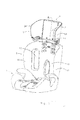
Fig.1 is a perspective drawing of the baby car seat in normal use according to the invention; -
Fig.2 is an exploded view of the baby car seat according to the invention; -
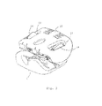
Fig.3 is a schematic drawing showing the packaging the baby car seat according to the invention; -
Fig.4 is a sectional view of thefig.1 along the line A-A, wherein the position adjustment mechanism is in the unlocked position and the head support body is in a low position; -
Fig.5 is a sectional view of thefig.1 along the line A-A, wherein the position adjustment mechanism is in the locked position and the head support body is in a high position; and -
Fig. 6 is an exploded view of the head support according to the invention. - As shown in
fig.s 1-3 , a baby car seat comprises aseat 1, abackrest 2 with a lower portion being detachably connected with a rear portion of theseat 1, ahead support 3 detachably connected with an upper portion of thebackrest 2. Thebackrest 2 comprises abackrest body 15 andbackrest wings 16 respectively located at a left side and a right side of thebackrest body 15. Thehead support 3 comprises ahead support body 4 andhead support wings 14 respectively located at a left side and a right side of thehead support body 4. Twoaccommodating holes 17 respectively are opened on a left part and a right part of thebackrest body 15, and the twoaccommodating holes 17 respectively are used for inserting thehead support wings 14 therein when thehead support 3 is accommodated between thebackrest wings 16. - The lower portion of the
backrest body 15 is detachably connected with the rear portion of theseat 1. The upper portion of thebackrest 15 is detachably connected with the lower portion of thehead support bracket 5 described hereinafter. The specific detachable configuration does not refer to the technical points of the invention, and thus will not be described in more detail herein. Any configurations can be used herein, provided that they can achieve the detachable connection between two parts. - The
backrest wings 16 and thebackrest body 15 are fixedly connected to each other to form a whole. Alternatively, thebackrest wings 16 and thebackrest body 15 are slidably connected with each other in the left-right direction, and a width adjusting mechanism is arranged between thebackrest wings 16 and thebackrest body 15. When the car seat is packaged, the twobackrest wings 16 may be adjusted into a widest position so that thehead support wings 14 can be inserted into the accommodating holes 17. Thehead support wings 14 is fixedly connected with thehead support body 4 to form a whole. - As shown in
fig.s 14-6 , thehead support 3 also comprises ahead support bracket 5, thehead support body 4 is slidably disposed on thehead support bracket 5 in the up-down direction, the lower portion of thehead support bracket 5 is detachably connected with the upper portion of thebackrest body 15, and a position adjustment mechanism is arranged between thehead support bracket 5 and thehead support body 4. When it is required to package and transport the car seat, thehead support bracket 5 is detached from thebackrest body 15, and the height between thehead support bracket 5 and thehead support body 4 is adjusted to a minimum value by the position adjustment mechanism, such that volume of the car seat after packaging is reduced. - The position adjustment mechanism comprises a plurality of
U-shaped locking grooves 9 which are formed as recesses by opening on a side of thehead support bracket 5, a position-limit groove 10 opened on thehead support body 4, anoperating handle 6 slidably disposed on thehead support body 4 along the up-down direction, and alocking pin 13. A guidinginclined groove 11 which is inclined in the up-down direction is opened on theoperating handle 6 for driving thelocking pin 13 to move. The lockingpin 13 is always inserted into the guidinginclined groove 11. The center lines of the lockinggrooves 9 and the position-limit groove 10 respectively extend along a direction perpendicular to the sliding direction of thehead support body 4. The plurality of lockinggrooves 9 are distributed on thehead support bracket 5 along the up-down direction. The position-limit groove 10 also is U-shaped. - The position adjustment mechanism has a locked position and an unlocked position. When the position adjustment mechanism is in the locked position, the locking
pin 13 is inserted into one of the lockinggrooves 9 which is corresponding to the position-limit groove 10, and the lockingpin 13 is located in a side portion of the guidinginclined groove 11. When the position adjustment mechanism is in the unlocked position, the lockingpin 3 is detached from all of the lockinggrooves 9, the lockingpin 13 is inserted into the position-limit groove 10, and the lockingpin 13 is located in the other side portion of the guidinginclined groove 11. The position adjustment mechanism also comprises an elastic member which makes the locking pin be steadily inserted into the lockinggroove 9. - The position-
limit groove 10 also may be a closed elongated groove (not shown). When the position adjustment mechanism is in the locked position, the lockingpin 13 is inserted into both one of the lockinggrooves 9 and the position-limit groove 10. - In the embodiment shown in
fig.s 4-5 , the center line of each lockinggroove 9 and the center line of the position-limit groove 10 respectively extend along the front-rear direction. The generic terms "front" and "rear" mentioned herein and throughout the invention are defined according to usual habits of a user, "front" refers to a side of the car seat where the seat is provided" "rear" refers to the back side of the car seat, and the front-rear direction refers to a direction of a line extending through the car seat from front to rear or from rear to front, and is not necessarily parallel to the horizontal plane. - The upper side portion of the guiding
inclined groove 11 is in the front, and the lower side portion of the guidinginclined groove 11 is in the rear. When the position adjustment mechanism is in the locked position, the lockingpin 13 is located is the upper side portion of the guidinginclined groove 11. When the position adjustment mechanism is in the unlocked position, the lockingpin 13 is located in the lower side portion of the guidinginclined groove 11. - The
elastic member 12 is arranged between the operatinghandle 6 and thehead support body 4. Specifically, theelastic member 12 is arranged between the operatinghandle 6 and therear cover plate 8 described hereinafter. Theelastic member 12 also may be directly disposed between the lockingpin 13 and thehead support body 4. - The position-
limit groove 10 also is U-shaped. When the position adjustment mechanism is in the locked position, the position-limit groove 10 and the lockinggroove 9 together constitute a closed groove. Thehead support body 4 comprises afront cover plate 7 and arear cover plate 8 fixedly connected with thefront cover plate 7. An accommodating space with a downward opening is formed between thefront cover plate 7 and therear cover plate 8. Thehead support bracket 5 and theoperating handle 6 are located in the accommodating space, and theoperating handle 6 is located between thehead support bracket 5 and therear cover plate 8. A window is opened on therear cover plate 8 for controlling theoperating handle 6. - The operation course of the baby car seat is as follows: the position adjustment mechanism in the locked position overcomes the elastic force of the
elastic member 12 to pull upwards theoperation handle 6, such that the lockingpin 13 is detached from the lockinggroove 9 under the cooperation of the position-limit groove 10 and the guidinginclined groove 11. Thehead support body 4 can be moved upwards or downwards, and when it is moved into an appropriate position, theoperating handle 6 is released and restores under the elastic force of theelastic member 12, such that the lockingpin 13 is inserted into thecorresponding locking groove 9. Provided that the upper side portion of the guidinginclined groove 11 is in the rear and the lower side portion of the guidinginclined groove 11 is in the front, it is required to press downwards theoperating handle 6 to convert the position adjustment mechanism from the locked position to the unlocked position. Thus, thehead support body 4 can be converted between a high position and a low position, that is to say, the height of thehead support body 4 can be adjusted. Furthermore, the car seat of the invention has a smaller volume when packaging. - The above embodiments are described for illustrating the technical concept and features of invention, the aim is intended to enable a person skilled in the art to appreciate the content of the invention and further implement it, and the protecting scope of the invention can not be limited hereby. Also, any equivalent variations or modifications made according to the spirit of the invention should be covered within the protecting scope of the invention.
Claims (11)
- A baby car seat, comprising
a seat (1);
a backrest (2) with a lower portion being detachably connected with a rear portion of the seat (1), the backrest (2) comprising a backrest body (15) and a pair of backrest wings (2) respectively extending forwards from a left end and a right end of the backrest body (15);
a head support (3) detachably connected with an upper portion of the backrest (2), which comprises a head support body (4) and a pair of head support wings (14) respectively extending forwards from a left side and a right side of the head support body (4); wherein two accommodating holes (17) are opened respectively on a left part and a right part of the backrest body (15) to be used for inserting the corresponding head support wings (14) therein when the head support (3) is accommodated between the two backrest wings (16), the shape and mutual distance of the two accommodating holes (17) being matched with that of the two head support wings (14) . - The baby car seat as claimed in claim 1, wherein the backrest wings (16) and the backrest body (15) are integrated into one-piece.
- The baby car seat as claimed in claim 1, wherein the head support wings (14) and the head support body (4) are integrated into one-piece.
- The baby car seat as claimed in claim 1, wherein the head support (3) also comprises a head support bracket (5) on which the head support body (4) is slidably disposed along a longitudinal direction of the head support (3), the head support (3) being connected with the backrest body (15) by a lower portion of the head support bracket (5), and a position adjustment mechanism being arranged between the head support bracket (5) and the head support body (4) for controlling the location of the head support body (4) relative to the head support bracket (5).
- The baby car seat as claimed in claim 4, wherein the position adjustment mechanism comprises:a plurality of locking grooves (9) which are formed as recesses by opening on a side of the head support bracket (5), and the plurality of locking grooves (9) being arranged along the longitudinal direction of the head support (3);a position-limit groove (10) opened on the head support body (4), the center line of the longitudinal section of the position-limit groove (10) being substantially parallel to the center line of the longitudinal section of each locking groove (9);a locking pin (13), which is slidably disposed within the position-limit groove (10) along the position-limit groove (10);an operating handle (6) slidably disposed on the head support body (4) along the longitudinal direction of the head support (3), a guiding inclined groove (11) being opened on the operating handle (6), and the guiding inclined groove (11) being inclined relative to the longitudinal direction of the head support (3) and the center line of the longitudinal section of the position-limit groove (10), and the locking pin (13) being inserted into the guiding inclined groove (11);wherein during the sliding of the operating handle (6) relative to the head support body (4), the locking pin (13) slides along the position-limit groove (10) under guiding of the guiding inclined groove (11) such that the position adjustment mechanism has a locked position and an unlocked position, when in the locked position, one of the locking grooves (9) is corresponding to the position-limit groove (10) and the locking pin (3) is inserted into the locking groove (9), and when in the unlocked position, the locking pin (3) is detached from the locking groove (9).
- The baby car seat as claimed in claim 5, wherein the position adjustment mechanism also comprises an elastic member which is used for applying a force on the locking pin (3) such that the locking pin (3) can be steadily inserted into the locking groove (9).
- The baby car seat as claimed in claim 5, wherein the center line of the longitudinal section of each locking groove (9) and the center line of the longitudinal section of the position-limit groove (10) respectively are perpendicular to the longitudinal direction of the head support (3).
- The baby car seat as claimed in claim 6, wherein the elastic member (12) is arranged between the operating handle (6) and the head support body (4).
- The baby car seat as claimed in claim 5, wherein the longitudinal section of locking groove (9) is U-shaped, such that the position-limit groove (10) forms a closed groove together with the locking groove (9) when the position adjustment mechanism is in the locked position.
- The baby car seat as claimed in claim 5 or 9, wherein the guiding inclined groove (11) has an upper side portion and a lower side portion, the upper side portion of the guiding inclined groove (11) is substantially corresponding to the locking groove (9) in the longitudinal direction and the lower side portion of the guiding inclined groove (11) is substantially corresponding to the outside of the opening of the locking groove (9) in such a way that: when the position adjustment mechanism is in the locked position, the locking pin (13) is in the upper side portion of the guiding inclined groove (11), when the position adjustment mechanism is in the unlocked position, the locking pin (13) is in the lower side portion of the guiding inclined groove (11).
- The baby car seat as claimed in any of claims 5-9, wherein the head support body (4) comprises a front cover plate (7) and a rear cover plate (8) fixedly connected with the front cover plate (7), an accommodating space with an downward opening being formed between the front cover plate (7) and the rear cover plate (8), the head support bracket (5) and the operating handle (6) being located in the accommodating space, and the operating handle (6) being located between the head support bracket (5) and the rear cover plate (8), and a window being opened on the rear cover plate (8) for allowing a user to stretch out his/her hand into the accommodating space to move the operating handle (6).
Applications Claiming Priority (2)
| Application Number | Priority Date | Filing Date | Title |
|---|---|---|---|
| CN2012202537879U CN202686018U (en) | 2012-05-31 | 2012-05-31 | Children vehicle seat |
| PCT/CN2013/076297 WO2013178046A1 (en) | 2012-05-31 | 2013-05-28 | Child car seat |
Publications (3)
| Publication Number | Publication Date |
|---|---|
| EP2857257A1 true EP2857257A1 (en) | 2015-04-08 |
| EP2857257A4 EP2857257A4 (en) | 2016-01-13 |
| EP2857257B1 EP2857257B1 (en) | 2019-09-18 |
Family
ID=47541679
Family Applications (1)
| Application Number | Title | Priority Date | Filing Date |
|---|---|---|---|
| EP13796436.7A Active EP2857257B1 (en) | 2012-05-31 | 2013-05-28 | Child car seat |
Country Status (6)
| Country | Link |
|---|---|
| US (1) | US9315125B2 (en) |
| EP (1) | EP2857257B1 (en) |
| CN (1) | CN202686018U (en) |
| BR (1) | BR112014030000A2 (en) |
| CA (1) | CA2875177C (en) |
| WO (1) | WO2013178046A1 (en) |
Cited By (1)
| Publication number | Priority date | Publication date | Assignee | Title |
|---|---|---|---|---|
| CN107199925A (en) * | 2017-05-04 | 2017-09-26 | 大连理工大学 | A kind of child safety seat flank width adjusting device |
Families Citing this family (12)
| Publication number | Priority date | Publication date | Assignee | Title |
|---|---|---|---|---|
| CN202686018U (en) * | 2012-05-31 | 2013-01-23 | 好孩子儿童用品有限公司 | Children vehicle seat |
| CN104760522B (en) * | 2014-01-06 | 2017-03-29 | 宝钜儿童用品香港股份有限公司 | Child safety seat |
| GB2537798A (en) * | 2014-11-11 | 2016-11-02 | James Hicks Ben | Child car seat |
| CN104972937A (en) * | 2015-07-08 | 2015-10-14 | 苏州逗乐儿童用品有限公司 | Automobile child seat |
| WO2017127496A1 (en) * | 2016-01-20 | 2017-07-27 | Dorel Juvenile Group, Inc. | Belt-mount system for juvenile vehicle seat |
| CN105711450A (en) * | 2016-01-21 | 2016-06-29 | 宁波永驰婴童用品有限公司 | Headrest height adjusting mechanism of child safety seat |
| US10106068B2 (en) * | 2017-01-05 | 2018-10-23 | Ford Global Technologies, Llc | Modular head restraint structure and styling enablement features |
| US10988056B2 (en) | 2017-03-23 | 2021-04-27 | Dorel Juvenile Group, Inc. | Child restraint headrest with side-wing mover |
| CN107813742B (en) * | 2017-09-27 | 2024-02-02 | 布童安全科技(宁波)有限公司 | A child safety seat and its preparation process |
| DE102017126431A1 (en) * | 2017-11-10 | 2019-05-16 | Recaro Child Safety Gmbh & Co. Kg | Child seat device |
| CN108657033B (en) * | 2018-05-17 | 2024-03-01 | 麦克英孚(宁波)婴童用品有限公司 | A safety seat with adjustable headrest |
| CN108705961B (en) * | 2018-06-22 | 2019-10-01 | 苏州纪宝儿童用品有限公司 | A kind of children's seat head rest mounting structure |
Family Cites Families (24)
| Publication number | Priority date | Publication date | Assignee | Title |
|---|---|---|---|---|
| GB2220848B (en) * | 1988-07-22 | 1991-04-24 | Mothercare Uk Ltd | Auxiliary seats |
| US5275462A (en) * | 1992-10-13 | 1994-01-04 | Seats Incorporated | Vehicle seat with pivotable head supports |
| FR2817811B1 (en) * | 2000-12-12 | 2004-11-26 | Faurecia Sieges Automobile | TRANSFORMABLE VEHICLE SEAT |
| US6623074B2 (en) * | 2001-04-05 | 2003-09-23 | Mattel, Inc. | Vehicle seat |
| US7066536B2 (en) * | 2002-02-11 | 2006-06-27 | Graco Children's Products Inc. | Child seat |
| US6908151B2 (en) * | 2003-03-07 | 2005-06-21 | Meeker R&D, Inc. | Adjustable and foldable booster car seat |
| US7055903B2 (en) * | 2004-01-09 | 2006-06-06 | Cosco Management, Inc. | Adjustor for juvenile vehicle seat |
| US7246852B2 (en) * | 2004-03-10 | 2007-07-24 | Cosco Management, Inc. | Headrest actuator for juvenile vehicle seat |
| US7021710B2 (en) * | 2004-03-10 | 2006-04-04 | Cosco Management, Inc. | Juvenile vehicle seat with movable headrest |
| JP4614204B2 (en) | 2005-01-24 | 2011-01-19 | 三菱自動車工業株式会社 | Sheet device |
| US7303230B2 (en) * | 2005-06-10 | 2007-12-04 | Cosco Management, Inc. | Juvenile vehicle seat with quick-connect backrest |
| US7322647B2 (en) * | 2005-06-10 | 2008-01-29 | Cosco Management, Inc. | Adjustable headrest for juvenile vehicle seat |
| US7625043B2 (en) * | 2005-09-15 | 2009-12-01 | Wonderland Nurserygoods Co., Ltd. | Child car seat with multiple use configurations |
| US20070236061A1 (en) * | 2006-06-30 | 2007-10-11 | Meeker R&D, Inc. | Low Cost Adjustable and Foldable Car Seat |
| US7452031B2 (en) * | 2006-11-10 | 2008-11-18 | Evenflo Company, Inc. | Multi-adjustable child seat with detachable softgoods attachment |
| US8141951B2 (en) * | 2008-09-10 | 2012-03-27 | Excellerate Enterprise Co., Ltd. | Child safety seat |
| NL1036865C2 (en) * | 2009-04-16 | 2010-10-19 | Maxi Miliaan Bv | Child vehicle seat. |
| CN201721359U (en) * | 2010-07-05 | 2011-01-26 | 浙江经济职业技术学院 | Built-in automobile seat |
| CN201792765U (en) * | 2010-09-03 | 2011-04-13 | 江苏幸运宝贝安全装置制造有限公司 | Safety seat of automobile for child |
| US8585138B2 (en) * | 2010-10-26 | 2013-11-19 | Cosco Management, Inc. | Rigidifying system for single shell juvenile vehicle seat |
| US9022471B2 (en) * | 2011-01-07 | 2015-05-05 | Cosco Management, Inc. | Headrest for juvenile vehicle seat |
| CN202098305U (en) * | 2011-03-01 | 2012-01-04 | 好孩子儿童用品有限公司 | Automobile chair for children |
| CN202686018U (en) * | 2012-05-31 | 2013-01-23 | 好孩子儿童用品有限公司 | Children vehicle seat |
| CN103144557B (en) * | 2013-03-11 | 2015-07-29 | 麦克英孚(宁波)婴童用品有限公司 | A kind of child's safety seat for vehicle |
-
2012
- 2012-05-31 CN CN2012202537879U patent/CN202686018U/en not_active Expired - Lifetime
-
2013
- 2013-05-28 EP EP13796436.7A patent/EP2857257B1/en active Active
- 2013-05-28 BR BR112014030000A patent/BR112014030000A2/en not_active Application Discontinuation
- 2013-05-28 WO PCT/CN2013/076297 patent/WO2013178046A1/en not_active Ceased
- 2013-05-28 US US14/404,614 patent/US9315125B2/en not_active Expired - Fee Related
- 2013-05-28 CA CA2875177A patent/CA2875177C/en active Active
Cited By (1)
| Publication number | Priority date | Publication date | Assignee | Title |
|---|---|---|---|---|
| CN107199925A (en) * | 2017-05-04 | 2017-09-26 | 大连理工大学 | A kind of child safety seat flank width adjusting device |
Also Published As
| Publication number | Publication date |
|---|---|
| CA2875177A1 (en) | 2013-12-05 |
| BR112014030000A2 (en) | 2017-06-27 |
| CA2875177C (en) | 2020-06-02 |
| EP2857257A4 (en) | 2016-01-13 |
| CN202686018U (en) | 2013-01-23 |
| US20150115670A1 (en) | 2015-04-30 |
| EP2857257B1 (en) | 2019-09-18 |
| US9315125B2 (en) | 2016-04-19 |
| WO2013178046A1 (en) | 2013-12-05 |
Similar Documents
| Publication | Publication Date | Title |
|---|---|---|
| EP2857257A1 (en) | Child car seat | |
| CN102371919B (en) | Child seat assembly and base thereof | |
| JP5840502B2 (en) | child seat | |
| US9873358B2 (en) | Locking device for baby car seat | |
| US8851345B2 (en) | Fastening device | |
| US7032922B1 (en) | Stroller with a detachable seat member | |
| JP2011057207A (en) | Child safety seat assembly | |
| CN103921697B (en) | Forward and backward car seat fixing device | |
| US9738182B2 (en) | Child seat for a motor vehicle | |
| JP2000177434A (en) | Instrument panel | |
| US20220219580A1 (en) | Adjustable protector and safety seat | |
| TWI903278B (en) | Carrier and base | |
| JP2003165388A (en) | Console box structure for vehicle | |
| KR102305202B1 (en) | Child seat | |
| KR20150000160U (en) | Rear seat for vehicle | |
| JP6473181B2 (en) | Vehicle seat and vehicle | |
| JP6293549B2 (en) | child seat | |
| JP2024159867A (en) | Seat belt adjustment structure | |
| KR102305203B1 (en) | Child seat | |
| AU2011101475A4 (en) | An adjustable shoulder strap mechanism for baby stroller | |
| JP4810300B2 (en) | Children's chairs and motorcycles | |
| CN204309632U (en) | A kind of automobile seat for child | |
| EP1591306A2 (en) | Child seat | |
| TWI899996B (en) | Adjusting mechanism, adjusting device for child carrier, and child carrier | |
| JP6338910B2 (en) | child seat |
Legal Events
| Date | Code | Title | Description |
|---|---|---|---|
| PUAI | Public reference made under article 153(3) epc to a published international application that has entered the european phase |
Free format text: ORIGINAL CODE: 0009012 |
|
| 17P | Request for examination filed |
Effective date: 20141217 |
|
| AK | Designated contracting states |
Kind code of ref document: A1 Designated state(s): AL AT BE BG CH CY CZ DE DK EE ES FI FR GB GR HR HU IE IS IT LI LT LU LV MC MK MT NL NO PL PT RO RS SE SI SK SM TR |
|
| AX | Request for extension of the european patent |
Extension state: BA ME |
|
| DAX | Request for extension of the european patent (deleted) | ||
| RA4 | Supplementary search report drawn up and despatched (corrected) |
Effective date: 20151211 |
|
| RIC1 | Information provided on ipc code assigned before grant |
Ipc: B60N 2/28 20060101AFI20151207BHEP Ipc: B60N 2/48 20060101ALI20151207BHEP |
|
| REG | Reference to a national code |
Ref country code: DE Ref legal event code: R079 Ref document number: 602013060734 Country of ref document: DE Free format text: PREVIOUS MAIN CLASS: B60N0002260000 Ipc: B60N0002280000 |
|
| GRAP | Despatch of communication of intention to grant a patent |
Free format text: ORIGINAL CODE: EPIDOSNIGR1 |
|
| RIC1 | Information provided on ipc code assigned before grant |
Ipc: B60N 2/28 20060101AFI20190325BHEP |
|
| STAA | Information on the status of an ep patent application or granted ep patent |
Free format text: STATUS: GRANT OF PATENT IS INTENDED |
|
| INTG | Intention to grant announced |
Effective date: 20190502 |
|
| GRAS | Grant fee paid |
Free format text: ORIGINAL CODE: EPIDOSNIGR3 |
|
| GRAA | (expected) grant |
Free format text: ORIGINAL CODE: 0009210 |
|
| STAA | Information on the status of an ep patent application or granted ep patent |
Free format text: STATUS: THE PATENT HAS BEEN GRANTED |
|
| AK | Designated contracting states |
Kind code of ref document: B1 Designated state(s): AL AT BE BG CH CY CZ DE DK EE ES FI FR GB GR HR HU IE IS IT LI LT LU LV MC MK MT NL NO PL PT RO RS SE SI SK SM TR |
|
| REG | Reference to a national code |
Ref country code: GB Ref legal event code: FG4D |
|
| REG | Reference to a national code |
Ref country code: CH Ref legal event code: EP |
|
| REG | Reference to a national code |
Ref country code: DE Ref legal event code: R096 Ref document number: 602013060734 Country of ref document: DE |
|
| REG | Reference to a national code |
Ref country code: AT Ref legal event code: REF Ref document number: 1180881 Country of ref document: AT Kind code of ref document: T Effective date: 20191015 |
|
| REG | Reference to a national code |
Ref country code: IE Ref legal event code: FG4D |
|
| REG | Reference to a national code |
Ref country code: NL Ref legal event code: MP Effective date: 20190918 |
|
| PG25 | Lapsed in a contracting state [announced via postgrant information from national office to epo] |
Ref country code: FI Free format text: LAPSE BECAUSE OF FAILURE TO SUBMIT A TRANSLATION OF THE DESCRIPTION OR TO PAY THE FEE WITHIN THE PRESCRIBED TIME-LIMIT Effective date: 20190918 Ref country code: SE Free format text: LAPSE BECAUSE OF FAILURE TO SUBMIT A TRANSLATION OF THE DESCRIPTION OR TO PAY THE FEE WITHIN THE PRESCRIBED TIME-LIMIT Effective date: 20190918 Ref country code: BG Free format text: LAPSE BECAUSE OF FAILURE TO SUBMIT A TRANSLATION OF THE DESCRIPTION OR TO PAY THE FEE WITHIN THE PRESCRIBED TIME-LIMIT Effective date: 20191218 Ref country code: NO Free format text: LAPSE BECAUSE OF FAILURE TO SUBMIT A TRANSLATION OF THE DESCRIPTION OR TO PAY THE FEE WITHIN THE PRESCRIBED TIME-LIMIT Effective date: 20191218 Ref country code: HR Free format text: LAPSE BECAUSE OF FAILURE TO SUBMIT A TRANSLATION OF THE DESCRIPTION OR TO PAY THE FEE WITHIN THE PRESCRIBED TIME-LIMIT Effective date: 20190918 Ref country code: LT Free format text: LAPSE BECAUSE OF FAILURE TO SUBMIT A TRANSLATION OF THE DESCRIPTION OR TO PAY THE FEE WITHIN THE PRESCRIBED TIME-LIMIT Effective date: 20190918 |
|
| REG | Reference to a national code |
Ref country code: LT Ref legal event code: MG4D |
|
| PG25 | Lapsed in a contracting state [announced via postgrant information from national office to epo] |
Ref country code: AL Free format text: LAPSE BECAUSE OF FAILURE TO SUBMIT A TRANSLATION OF THE DESCRIPTION OR TO PAY THE FEE WITHIN THE PRESCRIBED TIME-LIMIT Effective date: 20190918 Ref country code: LV Free format text: LAPSE BECAUSE OF FAILURE TO SUBMIT A TRANSLATION OF THE DESCRIPTION OR TO PAY THE FEE WITHIN THE PRESCRIBED TIME-LIMIT Effective date: 20190918 Ref country code: RS Free format text: LAPSE BECAUSE OF FAILURE TO SUBMIT A TRANSLATION OF THE DESCRIPTION OR TO PAY THE FEE WITHIN THE PRESCRIBED TIME-LIMIT Effective date: 20190918 Ref country code: GR Free format text: LAPSE BECAUSE OF FAILURE TO SUBMIT A TRANSLATION OF THE DESCRIPTION OR TO PAY THE FEE WITHIN THE PRESCRIBED TIME-LIMIT Effective date: 20191219 |
|
| REG | Reference to a national code |
Ref country code: AT Ref legal event code: MK05 Ref document number: 1180881 Country of ref document: AT Kind code of ref document: T Effective date: 20190918 |
|
| PG25 | Lapsed in a contracting state [announced via postgrant information from national office to epo] |
Ref country code: RO Free format text: LAPSE BECAUSE OF FAILURE TO SUBMIT A TRANSLATION OF THE DESCRIPTION OR TO PAY THE FEE WITHIN THE PRESCRIBED TIME-LIMIT Effective date: 20190918 Ref country code: PL Free format text: LAPSE BECAUSE OF FAILURE TO SUBMIT A TRANSLATION OF THE DESCRIPTION OR TO PAY THE FEE WITHIN THE PRESCRIBED TIME-LIMIT Effective date: 20190918 Ref country code: ES Free format text: LAPSE BECAUSE OF FAILURE TO SUBMIT A TRANSLATION OF THE DESCRIPTION OR TO PAY THE FEE WITHIN THE PRESCRIBED TIME-LIMIT Effective date: 20190918 Ref country code: NL Free format text: LAPSE BECAUSE OF FAILURE TO SUBMIT A TRANSLATION OF THE DESCRIPTION OR TO PAY THE FEE WITHIN THE PRESCRIBED TIME-LIMIT Effective date: 20190918 Ref country code: PT Free format text: LAPSE BECAUSE OF FAILURE TO SUBMIT A TRANSLATION OF THE DESCRIPTION OR TO PAY THE FEE WITHIN THE PRESCRIBED TIME-LIMIT Effective date: 20200120 Ref country code: IT Free format text: LAPSE BECAUSE OF FAILURE TO SUBMIT A TRANSLATION OF THE DESCRIPTION OR TO PAY THE FEE WITHIN THE PRESCRIBED TIME-LIMIT Effective date: 20190918 Ref country code: EE Free format text: LAPSE BECAUSE OF FAILURE TO SUBMIT A TRANSLATION OF THE DESCRIPTION OR TO PAY THE FEE WITHIN THE PRESCRIBED TIME-LIMIT Effective date: 20190918 Ref country code: AT Free format text: LAPSE BECAUSE OF FAILURE TO SUBMIT A TRANSLATION OF THE DESCRIPTION OR TO PAY THE FEE WITHIN THE PRESCRIBED TIME-LIMIT Effective date: 20190918 |
|
| PG25 | Lapsed in a contracting state [announced via postgrant information from national office to epo] |
Ref country code: CZ Free format text: LAPSE BECAUSE OF FAILURE TO SUBMIT A TRANSLATION OF THE DESCRIPTION OR TO PAY THE FEE WITHIN THE PRESCRIBED TIME-LIMIT Effective date: 20190918 Ref country code: SM Free format text: LAPSE BECAUSE OF FAILURE TO SUBMIT A TRANSLATION OF THE DESCRIPTION OR TO PAY THE FEE WITHIN THE PRESCRIBED TIME-LIMIT Effective date: 20190918 Ref country code: IS Free format text: LAPSE BECAUSE OF FAILURE TO SUBMIT A TRANSLATION OF THE DESCRIPTION OR TO PAY THE FEE WITHIN THE PRESCRIBED TIME-LIMIT Effective date: 20200224 Ref country code: SK Free format text: LAPSE BECAUSE OF FAILURE TO SUBMIT A TRANSLATION OF THE DESCRIPTION OR TO PAY THE FEE WITHIN THE PRESCRIBED TIME-LIMIT Effective date: 20190918 |
|
| REG | Reference to a national code |
Ref country code: DE Ref legal event code: R097 Ref document number: 602013060734 Country of ref document: DE |
|
| PLBE | No opposition filed within time limit |
Free format text: ORIGINAL CODE: 0009261 |
|
| STAA | Information on the status of an ep patent application or granted ep patent |
Free format text: STATUS: NO OPPOSITION FILED WITHIN TIME LIMIT |
|
| PG2D | Information on lapse in contracting state deleted |
Ref country code: IS |
|
| PG25 | Lapsed in a contracting state [announced via postgrant information from national office to epo] |
Ref country code: DK Free format text: LAPSE BECAUSE OF FAILURE TO SUBMIT A TRANSLATION OF THE DESCRIPTION OR TO PAY THE FEE WITHIN THE PRESCRIBED TIME-LIMIT Effective date: 20190918 Ref country code: IS Free format text: LAPSE BECAUSE OF FAILURE TO SUBMIT A TRANSLATION OF THE DESCRIPTION OR TO PAY THE FEE WITHIN THE PRESCRIBED TIME-LIMIT Effective date: 20200119 |
|
| 26N | No opposition filed |
Effective date: 20200619 |
|
| PG25 | Lapsed in a contracting state [announced via postgrant information from national office to epo] |
Ref country code: SI Free format text: LAPSE BECAUSE OF FAILURE TO SUBMIT A TRANSLATION OF THE DESCRIPTION OR TO PAY THE FEE WITHIN THE PRESCRIBED TIME-LIMIT Effective date: 20190918 |
|
| PG25 | Lapsed in a contracting state [announced via postgrant information from national office to epo] |
Ref country code: MC Free format text: LAPSE BECAUSE OF FAILURE TO SUBMIT A TRANSLATION OF THE DESCRIPTION OR TO PAY THE FEE WITHIN THE PRESCRIBED TIME-LIMIT Effective date: 20190918 Ref country code: CH Free format text: LAPSE BECAUSE OF NON-PAYMENT OF DUE FEES Effective date: 20200531 Ref country code: LI Free format text: LAPSE BECAUSE OF NON-PAYMENT OF DUE FEES Effective date: 20200531 |
|
| REG | Reference to a national code |
Ref country code: BE Ref legal event code: MM Effective date: 20200531 |
|
| GBPC | Gb: european patent ceased through non-payment of renewal fee |
Effective date: 20200528 |
|
| PG25 | Lapsed in a contracting state [announced via postgrant information from national office to epo] |
Ref country code: LU Free format text: LAPSE BECAUSE OF NON-PAYMENT OF DUE FEES Effective date: 20200528 |
|
| PG25 | Lapsed in a contracting state [announced via postgrant information from national office to epo] |
Ref country code: IE Free format text: LAPSE BECAUSE OF NON-PAYMENT OF DUE FEES Effective date: 20200528 Ref country code: GB Free format text: LAPSE BECAUSE OF NON-PAYMENT OF DUE FEES Effective date: 20200528 Ref country code: FR Free format text: LAPSE BECAUSE OF NON-PAYMENT OF DUE FEES Effective date: 20200531 |
|
| PG25 | Lapsed in a contracting state [announced via postgrant information from national office to epo] |
Ref country code: BE Free format text: LAPSE BECAUSE OF NON-PAYMENT OF DUE FEES Effective date: 20200531 |
|
| PG25 | Lapsed in a contracting state [announced via postgrant information from national office to epo] |
Ref country code: TR Free format text: LAPSE BECAUSE OF FAILURE TO SUBMIT A TRANSLATION OF THE DESCRIPTION OR TO PAY THE FEE WITHIN THE PRESCRIBED TIME-LIMIT Effective date: 20190918 Ref country code: MT Free format text: LAPSE BECAUSE OF FAILURE TO SUBMIT A TRANSLATION OF THE DESCRIPTION OR TO PAY THE FEE WITHIN THE PRESCRIBED TIME-LIMIT Effective date: 20190918 Ref country code: CY Free format text: LAPSE BECAUSE OF FAILURE TO SUBMIT A TRANSLATION OF THE DESCRIPTION OR TO PAY THE FEE WITHIN THE PRESCRIBED TIME-LIMIT Effective date: 20190918 |
|
| PG25 | Lapsed in a contracting state [announced via postgrant information from national office to epo] |
Ref country code: MK Free format text: LAPSE BECAUSE OF FAILURE TO SUBMIT A TRANSLATION OF THE DESCRIPTION OR TO PAY THE FEE WITHIN THE PRESCRIBED TIME-LIMIT Effective date: 20190918 |
|
| PGFP | Annual fee paid to national office [announced via postgrant information from national office to epo] |
Ref country code: DE Payment date: 20230530 Year of fee payment: 11 |
|
| REG | Reference to a national code |
Ref country code: DE Ref legal event code: R119 Ref document number: 602013060734 Country of ref document: DE |
|
| PG25 | Lapsed in a contracting state [announced via postgrant information from national office to epo] |
Ref country code: DE Free format text: LAPSE BECAUSE OF NON-PAYMENT OF DUE FEES Effective date: 20241203 |