EP2857118A1 - Method for manufacturing tube shaped part with different diameters and forming mold - Google Patents
Method for manufacturing tube shaped part with different diameters and forming mold Download PDFInfo
- Publication number
- EP2857118A1 EP2857118A1 EP20130798156 EP13798156A EP2857118A1 EP 2857118 A1 EP2857118 A1 EP 2857118A1 EP 20130798156 EP20130798156 EP 20130798156 EP 13798156 A EP13798156 A EP 13798156A EP 2857118 A1 EP2857118 A1 EP 2857118A1
- Authority
- EP
- European Patent Office
- Prior art keywords
- shape forming
- forming die
- diameter portion
- die set
- blank
- Prior art date
- Legal status (The legal status is an assumption and is not a legal conclusion. Google has not performed a legal analysis and makes no representation as to the accuracy of the status listed.)
- Granted
Links
Images



Classifications
-
- B—PERFORMING OPERATIONS; TRANSPORTING
- B21—MECHANICAL METAL-WORKING WITHOUT ESSENTIALLY REMOVING MATERIAL; PUNCHING METAL
- B21C—MANUFACTURE OF METAL SHEETS, WIRE, RODS, TUBES, PROFILES OR LIKE SEMI-MANUFACTURED PRODUCTS OTHERWISE THAN BY ROLLING; AUXILIARY OPERATIONS USED IN CONNECTION WITH METAL-WORKING WITHOUT ESSENTIALLY REMOVING MATERIAL
- B21C37/00—Manufacture of metal sheets, rods, wire, tubes, profiles or like semi-manufactured products, not otherwise provided for; Manufacture of tubes of special shape
- B21C37/06—Manufacture of metal sheets, rods, wire, tubes, profiles or like semi-manufactured products, not otherwise provided for; Manufacture of tubes of special shape of tubes or metal hoses; Combined procedures for making tubes, e.g. for making multi-wall tubes
- B21C37/15—Making tubes of special shape; Making tube fittings
- B21C37/16—Making tubes with varying diameter in longitudinal direction
-
- B—PERFORMING OPERATIONS; TRANSPORTING
- B21—MECHANICAL METAL-WORKING WITHOUT ESSENTIALLY REMOVING MATERIAL; PUNCHING METAL
- B21D—WORKING OR PROCESSING OF SHEET METAL OR METAL TUBES, RODS OR PROFILES WITHOUT ESSENTIALLY REMOVING MATERIAL; PUNCHING METAL
- B21D5/00—Bending sheet metal along straight lines, e.g. to form simple curves
- B21D5/01—Bending sheet metal along straight lines, e.g. to form simple curves between rams and anvils or abutments
-
- B—PERFORMING OPERATIONS; TRANSPORTING
- B21—MECHANICAL METAL-WORKING WITHOUT ESSENTIALLY REMOVING MATERIAL; PUNCHING METAL
- B21D—WORKING OR PROCESSING OF SHEET METAL OR METAL TUBES, RODS OR PROFILES WITHOUT ESSENTIALLY REMOVING MATERIAL; PUNCHING METAL
- B21D5/00—Bending sheet metal along straight lines, e.g. to form simple curves
- B21D5/01—Bending sheet metal along straight lines, e.g. to form simple curves between rams and anvils or abutments
- B21D5/015—Bending sheet metal along straight lines, e.g. to form simple curves between rams and anvils or abutments for making tubes
-
- B—PERFORMING OPERATIONS; TRANSPORTING
- B21—MECHANICAL METAL-WORKING WITHOUT ESSENTIALLY REMOVING MATERIAL; PUNCHING METAL
- B21C—MANUFACTURE OF METAL SHEETS, WIRE, RODS, TUBES, PROFILES OR LIKE SEMI-MANUFACTURED PRODUCTS OTHERWISE THAN BY ROLLING; AUXILIARY OPERATIONS USED IN CONNECTION WITH METAL-WORKING WITHOUT ESSENTIALLY REMOVING MATERIAL
- B21C37/00—Manufacture of metal sheets, rods, wire, tubes, profiles or like semi-manufactured products, not otherwise provided for; Manufacture of tubes of special shape
- B21C37/06—Manufacture of metal sheets, rods, wire, tubes, profiles or like semi-manufactured products, not otherwise provided for; Manufacture of tubes of special shape of tubes or metal hoses; Combined procedures for making tubes, e.g. for making multi-wall tubes
- B21C37/08—Making tubes with welded or soldered seams
- B21C37/0815—Making tubes with welded or soldered seams without continuous longitudinal movement of the sheet during the bending operation
-
- B—PERFORMING OPERATIONS; TRANSPORTING
- B21—MECHANICAL METAL-WORKING WITHOUT ESSENTIALLY REMOVING MATERIAL; PUNCHING METAL
- B21D—WORKING OR PROCESSING OF SHEET METAL OR METAL TUBES, RODS OR PROFILES WITHOUT ESSENTIALLY REMOVING MATERIAL; PUNCHING METAL
- B21D37/00—Tools as parts of machines covered by this subclass
- B21D37/16—Heating or cooling
-
- B—PERFORMING OPERATIONS; TRANSPORTING
- B21—MECHANICAL METAL-WORKING WITHOUT ESSENTIALLY REMOVING MATERIAL; PUNCHING METAL
- B21C—MANUFACTURE OF METAL SHEETS, WIRE, RODS, TUBES, PROFILES OR LIKE SEMI-MANUFACTURED PRODUCTS OTHERWISE THAN BY ROLLING; AUXILIARY OPERATIONS USED IN CONNECTION WITH METAL-WORKING WITHOUT ESSENTIALLY REMOVING MATERIAL
- B21C37/00—Manufacture of metal sheets, rods, wire, tubes, profiles or like semi-manufactured products, not otherwise provided for; Manufacture of tubes of special shape
- B21C37/06—Manufacture of metal sheets, rods, wire, tubes, profiles or like semi-manufactured products, not otherwise provided for; Manufacture of tubes of special shape of tubes or metal hoses; Combined procedures for making tubes, e.g. for making multi-wall tubes
- B21C37/15—Making tubes of special shape; Making tube fittings
- B21C37/16—Making tubes with varying diameter in longitudinal direction
- B21C37/18—Making tubes with varying diameter in longitudinal direction conical tubes
- B21C37/185—Making tubes with varying diameter in longitudinal direction conical tubes starting from sheet material
-
- Y—GENERAL TAGGING OF NEW TECHNOLOGICAL DEVELOPMENTS; GENERAL TAGGING OF CROSS-SECTIONAL TECHNOLOGIES SPANNING OVER SEVERAL SECTIONS OF THE IPC; TECHNICAL SUBJECTS COVERED BY FORMER USPC CROSS-REFERENCE ART COLLECTIONS [XRACs] AND DIGESTS
- Y10—TECHNICAL SUBJECTS COVERED BY FORMER USPC
- Y10S—TECHNICAL SUBJECTS COVERED BY FORMER USPC CROSS-REFERENCE ART COLLECTIONS [XRACs] AND DIGESTS
- Y10S72/00—Metal deforming
- Y10S72/70—Deforming specified alloys or uncommon metal or bimetallic work
Definitions
- the present invention relates to a method for manufacturing a pipe with different diameters along a longitudinal direction, and in particular, relates to a manufacturing method using press forming and to a press forming die for the pipe with different diameters along a longitudinal direction (refers to a pipe having a portion where the pipe diameter varies in the pipe axis direction), which has high dimensional accuracy and is manufactured at high productivity by press forming a blank made of a metal sheet (for example, a high-strength steel sheet having a tensile strength (TS) of equal to or more than 300 Mpa).
- a metal sheet for example, a high-strength steel sheet having a tensile strength (TS) of equal to or more than 300 Mpa
- the blank refers to a material for forming, which is a single flat sheet cut from an original sheet and has a shape corresponding to the shape of the pipe having undergone the forming.
- Pipes having a circular section having good rigidity and good collision strength are used for some automative parts. Also, many parts having a varying diameter are used from the viewpoint of joining to other parts.
- As a manufacturing process to obtain the pipe with different diameters along a longitudinal direction there are methods in which metal pipes manufactured by a process such as a UOE process or roll forming are subjected to secondary processing for pipes such as reducing, flaring, or hydroforming (these methods are referred to as related art I). There also is related-art regarding a method for manufacturing the pipe with different diameters along a longitudinal direction formed by press forming.
- Patent Literature 1 in order to suppress defects such as wrinkling and reduction of the sheet thickness after forming, the shape of the blank is improved and O-shape forming is performed after a U-shape forming has been performed.
- Patent Literature 1 Japanese Patent No. 4713471
- the inventors intently studied to address the above-described problem, and found the following. That is, in a pipe having a small diameter portion, a large diameter portion, and a diameter-changing portion provided therebetween, by setting the ratios of the sheet thickness of the material to the diameter of a forming die set corresponding to the small diameter portion and to the diameter of the forming die set corresponding to the large diameter portion in an adequate range, local variation in sheet thickness and wrinkling occurring in a part having been formed can be prevented. Furthermore, by introducing compressive strain in the circumferential direction during forming, the circularity of the part can be improved.
- wrinkling can be suppressed by increasing a vertical wall length of the U-shape forming die, and forming can be performed without an additional step or a core by using a circular cross-section forming die set with die mating lines downwardly inclined.
- the present invention has been proposed on the basis of the above-described findings and the gist thereof is as follows.
- a pipe with different diameters along a longitudinal direction having a high circularity can be manufactured in a minimum number of press forming steps.
- Fig. 1 is a single view drawing illustrating an example of an embodiment of the present invention.
- View (a) of Fig. 2 is a plan view of a blank corresponding to the example in Fig. 1 .
- reference sign 1 denotes a pipe with different diameters along a longitudinal direction
- reference sign 2 denotes a blank.
- the blank 2 having a thickness of t is press formed into the pipe with different diameters along a longitudinal direction 1.
- the pipe with different diameters along a longitudinal direction 1 has a small diameter portion, a large diameter portion, and a diameter-changing portion provided therebetween.
- the diameter-changing portion has a shape in which the large diameter portion and the small diameter portion are linearly connected to each other.
- the blank 2 has a planar shape having a large width portion (width La), a small width portion (width Lb), and a width-changing portion connecting the large and small width portions to each other.
- the large width portion, the small width portion, and the width-changing portion respectively correspond to the large diameter portion, the small diameter portion, and the diameter-changing portion.
- View (b) of Fig. 2 is a plan view illustrating a blank with notches formed at a boundary between the large diameter portion and the width-changing portion as a measure against wrinkling during forming. A blank having this shape may be used.
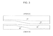
- Fig. 3 is a side view illustrating an example of an O-shape forming die set according to the present invention.
- the die set corresponds to the pipe with different diameters along a longitudinal direction illustrated in Fig. 1 .
- a region between A1 and A2 and a region between B1 and B2 represent die mating surfaces.
- A1 and A2 respectively correspond to B1 and B2 at a bottom dead point of the die set.
- the circularity is a parameter indicating the deviation from a target diameter and is calculated as follows. That is, the outer diameter of the pipe with different diameters along a longitudinal direction is measured at least eight angularly equally spaced positions, and the circularity is calculated with the following expression: (maximum outer diameter - minimum outer diameter)/diameter of die set x 100 (%).
- the compressive strain in the circumferential direction is a value calculated with the aforementioned expression (1).
- the ratio (t/D) is a parameter that affects the circularity and buckling during forming.
- t/D is specified to be equal to or more than 0.010.
- t/D is specified to be equal to or less than 0.080. Both the above-described Db and Da is represented by D.
- an angle ⁇ (inclination angle) formed between portions of the die set corresponding to the large diameter portion and the diameter-changing portion is preferably equal to or smaller than 30 degrees.
- Compressive strain in a pipe circumferential direction is an important parameter in reducing the distance between edges of the butting portions and reliably obtaining the circularity in the cross-section of a formed product.
- the blank With the compressive strain in the pipe circumferential direction applied, the blank is brought into tight contact with the dies at a last stage of the circular cross-section forming step. This improves the circularity.
- the circular cross-section is formed by compressive bending, springback deformation after removal from the dies is reduced and the distance between edges of the butting portions is reduced. Since the butting portions are joined to each other by, for example, welding after the forming, as the distance between edges is reduced, accuracy in butting during joining is improved, and accordingly, the joining work is facilitated.
- the compressive strain in the pipe circumferential direction is specified to be equal to or more than 0.5%.
- the compressive strain in the pipe circumferential direction is preferably equal to or less than 5%.
- the compressive strain is preferably equal to or less than 2.0%.
- the pipe with different diameters along a longitudinal direction is manufactured by, for example, as illustrated in Figs. 4 to 7 , press forming including the following two steps: a step in which the blank 2 is formed into a U-shape so as to obtain a U-shaped formed part 3; and a step in which circular cross-section forming is performed on the obtained U-shaped formed part 3 so as to obtain the circular cross-section formed part 4.
- a U-shaped forming illustrated in Fig. 4 is a forming. It is important in designing that a vertical wall length of a lower die of the U-shape forming die set used for the forming is longer than a target vertical wall portion length of the U-shaped formed part 3. Wrinkling tend to occur at portion between the large diameter portion and the diameter-changing portion during U-shape forming, and performing circular cross-section forming on the blank, in which wrinkling occurs, may cause various forming defects or damage to the dies. The wrinkling during the U-shape forming can be reduced by increasing the vertical wall length of the die and performing ironing on portions of the blank 2 corresponding to the vertical walls of the U-shaped formed part during the U-shape forming.
- the sectional shape of the U-shaped formed part 3 after removal from the dies is a U-shape that is opened due to springback deformation.
- U-shape forming by providing a bent shape between the large diameter portion and the diameter-changing portion, wrinkles between the large diameter portion and the diameter-changing portion, the wrinkles tending to be formed in the next O-shape forming step can be further reduced.
- An increase in a bending angle ⁇ 1 during U-shape forming is effective to suppress wrinkling as an angle ⁇ formed between the large diameter portion and the diameter-changing portion of a component is increased.
- ⁇ 1 is preferably equal to or smaller than 10 degrees.
- upper and lower dies have semi-circular shapes, and the die mating surfaces are not horizontal but inclined downwardly.
- the circular cross-section forming step is performed as follows. Initially, the U-shaped formed part 3 is set in the lower die, and the upper die is moved down. In so doing, since the U-shaped formed part 3 has an open U-shaped section as described above, the edges of the vertical wall portions of the U-shaped formed part 3 are brought into contact with the mating surfaces in the up-down direction. However, since the die mating surfaces are inclined downwardly, the edges of the vertical wall portions slide against the die mating surfaces. Thus, forming can be advanced without opening of the vertical wall portions.
- the die mating surfaces may have a linear shape.
- the edges of the vertical wall portions can be moved with increased smoothness. After that, the edges of the left and right vertical wall portions are brought into contact with each other, and the U-shaped formed part 3 is deformed while being bent so as to conform to the shape of the dies and formed to have a circular cross-section. After the circular cross-section formed part 4 has been removed from the dies, there is a distance between the edges of the butting portions due to sprinback deformation. When the compressive strain in the circumferential direction is small, the U-shaped formed part 3 does not sufficiently conform to the shape of the dies, and the circularity is reduced because bending lines remain. Furthermore, since the sprinback deformation is increased, the distance between edges at the butting portions is increased. The butting portions are joined to each other after the circular cross-section formed part 4 has been removed from the dies, thereby a final product is obtained.
- the butting portions need to be joined.
- a joining method include welding such as laser welding, arc welding, and spot welding.
- welding such as laser welding, arc welding, and spot welding.
- the blank is a thin material
- joining is difficult in some cases due to problems such as burn-through.
- With flanges the joining is easily performed.
- Fig. 7 with a slot formed at the top of an arc portion of the upper die, the edges of the left and right vertical walls are brought into contact with each other in the slot during forming and, after that, the circular cross-section is formed.
- the circular cross-section formed part with flanges can be formed.
- W/t is preferably equal to or more than 2.0.
- W/t is preferably equal to or less than 3.0.
- the circular cross-section formed parts having an entire length of 1400 mm and the shape illustrated in Fig. 1 are formed of blanks, which are made by cutting steel sheets having mechanical characteristics illustrated in Table 1, by press forming in the forms illustrated in Figs. 4 , 6 , and 7 performed under various conditions shown in Table 2.
- circumferential butting end portions at a plurality of positions in the pipe axis direction are tack welded to one another in each of the circular cross-section formed parts.
- the shapes of the circular cross-section formed parts are evaluated by measuring the circularity and visually determining the presence or absence of forming defects such as wrinkling and buckling.
- the inclination angle formed between the large diameter portion and the small diameter portion can be calculated from the length of the diameter-changing portion and the diameters of the die set corresponding to the large diameter portion and the small diameter portion (4.8 to 9.7 degrees in the present invention examples).
- Each of the examples exhibits a good circularity without forming defects such as wrinkling and buckling.
- the circularity is degraded and buckling occurs in No. 14 because t/Da of it is small. Since No. 15 has large t/Db, it is difficult to obtain the circularity with No. 15 even when the circumferential compressive strain is increased. The circularity is not obtained with No. 16.
Landscapes
- Engineering & Computer Science (AREA)
- Mechanical Engineering (AREA)
- Shaping Metal By Deep-Drawing, Or The Like (AREA)
- Bending Of Plates, Rods, And Pipes (AREA)
Abstract
Description
- The present invention relates to a method for manufacturing a pipe with different diameters along a longitudinal direction, and in particular, relates to a manufacturing method using press forming and to a press forming die for the pipe with different diameters along a longitudinal direction (refers to a pipe having a portion where the pipe diameter varies in the pipe axis direction), which has high dimensional accuracy and is manufactured at high productivity by press forming a blank made of a metal sheet (for example, a high-strength steel sheet having a tensile strength (TS) of equal to or more than 300 Mpa).
- Here, the blank refers to a material for forming, which is a single flat sheet cut from an original sheet and has a shape corresponding to the shape of the pipe having undergone the forming.
- Pipes (having a circular section) having good rigidity and good collision strength are used for some automative parts. Also, many parts having a varying diameter are used from the viewpoint of joining to other parts. As a manufacturing process to obtain the pipe with different diameters along a longitudinal direction, there are methods in which metal pipes manufactured by a process such as a UOE process or roll forming are subjected to secondary processing for pipes such as reducing, flaring, or hydroforming (these methods are referred to as related art I). There also is related-art regarding a method for manufacturing the pipe with different diameters along a longitudinal direction formed by press forming. According to this known forming method (see
Patent Literature 1; referred to as related art II), in order to suppress defects such as wrinkling and reduction of the sheet thickness after forming, the shape of the blank is improved and O-shape forming is performed after a U-shape forming has been performed. - Patent Literature 1: Japanese Patent No.
4713471 - With the related art I, pipes having been formed are subjected to secondary processing such as reducing, flaring, or tube forming. Thus, dedicated processing apparatuses are required. This may reduce productivity and lead to an increase in the cost. Furthermore, the reducing and the flaring are performed on limited positions in many cases, that is, mainly on positions near ends of pipes. Thus, there is a problem with versatility in these methods. With tube hydroforming, the sectional shape can be arbitrarily changed in the longitudinal direction. However, the sheet thickness of protruding portion is significantly reduced. Thus, it is difficult to obtain a component having a uniform thickness. In addition, since the time required for forming is long, there is a problem with productivity.
- In the related art II, vertical wall portions of a U-shaped formed part are inserted into an upper die during O-shape forming. This requires a core referred to as a guide blade. A step, in which end portions of the blank are bent inwardly, is also required before U-shape forming is performed. Furthermore, in the related art I, accuracy in sectional dimensions in a formed product is not described. The accuracy in sectional dimensions is important when a formed product is used as an automative part from the viewpoint of the performance of the part such as rigidity and for assembling. That is, there are problems with the manufacturing cost and the accuracy in product dimensions in the related art II.
- That is, with the related art, there is a problem in that a pipe with different diameters along a longitudinal direction, which is manufactured at high productivity and a low cost and with good accuracy in product dimensions, cannot be provided.
- The inventors intently studied to address the above-described problem, and found the following. That is, in a pipe having a small diameter portion, a large diameter portion, and a diameter-changing portion provided therebetween, by setting the ratios of the sheet thickness of the material to the diameter of a forming die set corresponding to the small diameter portion and to the diameter of the forming die set corresponding to the large diameter portion in an adequate range, local variation in sheet thickness and wrinkling occurring in a part having been formed can be prevented. Furthermore, by introducing compressive strain in the circumferential direction during forming, the circularity of the part can be improved. Furthermore, after the U-shape forming has been performed, in a die set used for manufacturing in a forming step of circular cross-section, wrinkling can be suppressed by increasing a vertical wall length of the U-shape forming die, and forming can be performed without an additional step or a core by using a circular cross-section forming die set with die mating lines downwardly inclined.
- The present invention has been proposed on the basis of the above-described findings and the gist thereof is as follows.
- (1) A method for manufacturing a pipe with different diameters along a longitudinal direction that has a small diameter portion, a large diameter portion, and a diameter-changing portion provided between the small diameter portion and the large diameter portion and is formed by press forming a blank made of a metal sheet. The method includes a step of press forming the blank with a U-shape forming die into a U-shaped formed part and press forming the U-shaped formed part with an O-shape forming die set into a circular cross-section formed part. A length of a vertical wall of the U-shape forming die is longer than a length of a vertical wall portion of the U-shaped formed part. In the O-shape forming die set, a die mating line is inclined downwardly, a ratio t/D of a sheet thickness t of the blank to a diameter D, which represents a diameter of a portion of the O-shape forming die set corresponding to the small diameter portion and a diameter of a portion of the O-shape forming die set corresponding to the large diameter portion, is 0.010 ≤ t/D ≤ 0.080, and a circumferential compressive strain given by the following expression (1) is equal to or more than 0.5%.

- (2) The method for manufacturing the pipe with different diameters along a longitudinal direction according to (1) described above, in which, in the U-shape forming, a bent shape is provided between the large diameter portion and the diameter-changing portion.
- (3) The method for manufacturing the pipe with different diameters along a longitudinal direction according to (1) or (2) described above, in which a slot is provided at a top of an arc portion of an upper die of the O-shape forming die set, and a ratio W/t of a slot width W of the slot to the sheet thickness t of the blank is from 2.0 to 3.0.
- (4) A forming die sets, which is used in the method for manufacturing according to any one of (1) to (3) described above, includes the U-shape forming die to be initially used and the O-shape forming die set to be used after the U-shape forming die has been used.
- According to the present invention, a pipe with different diameters along a longitudinal direction having a high circularity can be manufactured in a minimum number of press forming steps.
-
- [
Fig. 1] Fig. 1 is a single view drawing illustrating an example of an embodiment of the present invention. - [
Fig. 2 ] View (a) ofFig. 2 is a plan view of a blank corresponding to the example illustrated inFig. 1 . View (b) ofFig. 2 is a plan view illustrating a blank with notches, which is formed at a boundary between a large diameter portion and a width-changing portion for addressing wrinkling during forming. - [
Fig. 3] Fig. 3 is a side view illustrating an example of an O-shape forming die set according to the present invention. - [
Fig. 4] Fig. 4 includes sectional views illustrating an example of a U-shape forming step according to the present invention. - [
Fig. 5] Fig. 5 includes schematic views illustrating an example of a U-shape forming die according to the present invention. - [
Fig. 6] Fig. 6 includes sectional views illustrating an example of a circular cross-section forming step according to the present invention. - [
Fig. 7] Fig. 7 includes sectional views illustrating an example of a circular cross-section forming step (using a slotted upper die) according to the present invention. -
Fig. 1 is a single view drawing illustrating an example of an embodiment of the present invention. View (a) ofFig. 2 is a plan view of a blank corresponding to the example inFig. 1 . InFig. 1 and view (a) ofFig. 2 ,reference sign 1 denotes a pipe with different diameters along a longitudinal direction andreference sign 2 denotes a blank. The blank 2 having a thickness of t is press formed into the pipe with different diameters along alongitudinal direction 1. The pipe with different diameters along alongitudinal direction 1 has a small diameter portion, a large diameter portion, and a diameter-changing portion provided therebetween. The diameter-changing portion has a shape in which the large diameter portion and the small diameter portion are linearly connected to each other. The blank 2 has a planar shape having a large width portion (width La), a small width portion (width Lb), and a width-changing portion connecting the large and small width portions to each other. The large width portion, the small width portion, and the width-changing portion respectively correspond to the large diameter portion, the small diameter portion, and the diameter-changing portion. View (b) ofFig. 2 is a plan view illustrating a blank with notches formed at a boundary between the large diameter portion and the width-changing portion as a measure against wrinkling during forming. A blank having this shape may be used. -
Fig. 3 is a side view illustrating an example of an O-shape forming die set according to the present invention. The die set corresponds to the pipe with different diameters along a longitudinal direction illustrated inFig. 1 . InFig. 3 , a region between A1 and A2 and a region between B1 and B2 represent die mating surfaces. A1 and A2 respectively correspond to B1 and B2 at a bottom dead point of the die set. - Regarding the shape of the pipe with different diameters along a
longitudinal direction 1, in order to reduce wrinkling and reliably obtain a good circularity, it is important to control the following i) and ii) to appropriate values: - i) the ratios (t/D) of the blank thickness (t) to the diameter (D), which represents diameters of portions of the die set corresponding to the small diameter portion and the large diameter portion (D represents Db for the diameter of the small diameter portion and Da for the diameter of the large diameter portion), and
- ii) compressive strain in the circumferential direction.
- Here, the circularity is a parameter indicating the deviation from a target diameter and is calculated as follows. That is, the outer diameter of the pipe with different diameters along a longitudinal direction is measured at least eight angularly equally spaced positions, and the circularity is calculated with the following expression: (maximum outer diameter - minimum outer diameter)/diameter of die set x 100 (%). The compressive strain in the circumferential direction is a value calculated with the aforementioned expression (1).
- The ratio (t/D) is a parameter that affects the circularity and buckling during forming.
- When t/D is excessively small, that is, the sheet thickness is excessively small or the diameter is excessively large, buckling tends to occur in a circular cross-section forming step, which will be described later, and furthermore, sufficient compressive strain in the circumferential direction cannot be applied, thereby the circularity is degraded. In order to address this, t/D is specified to be equal to or more than 0.010. When t/D is excessively large, that is, the sheet thickness is excessively large or the diameter is excessively small, the blank fails to sufficiently conform to the shape of the die set during circular cross-section forming, thereby the circularity is degraded. In order to address this, t/D is specified to be equal to or less than 0.080. Both the above-described Db and Da is represented by D.
- From the viewpoint of reduction of wrinkling in forming near butting portion between the large diameter portion and the diameter-changing portion, an angle θ (inclination angle) formed between portions of the die set corresponding to the large diameter portion and the diameter-changing portion is preferably equal to or smaller than 30 degrees.
- Compressive strain in a pipe circumferential direction is an important parameter in reducing the distance between edges of the butting portions and reliably obtaining the circularity in the cross-section of a formed product. With the compressive strain in the pipe circumferential direction applied, the blank is brought into tight contact with the dies at a last stage of the circular cross-section forming step. This improves the circularity. Furthermore, since the circular cross-section is formed by compressive bending, springback deformation after removal from the dies is reduced and the distance between edges of the butting portions is reduced. Since the butting portions are joined to each other by, for example, welding after the forming, as the distance between edges is reduced, accuracy in butting during joining is improved, and accordingly, the joining work is facilitated. In order to obtain the circularity of 2.0% or less, the compressive strain in the pipe circumferential direction is specified to be equal to or more than 0.5%. When the compressive strain in the pipe circumferential direction is large, there may be biting of the material on the die mating surfaces or an increase in a forming load. For this reason, the compressive strain in the pipe circumferential direction is preferably equal to or less than 5%. In the case where the sheet thickness is small and the diameter is large, increasing the compressive strain leads to buckling. Thus, when the t/D is equal to or less than 0.020, the compressive strain is preferably equal to or less than 2.0%.
- The pipe with different diameters along a longitudinal direction according to the present invention is manufactured by, for example, as illustrated in
Figs. 4 to 7 , press forming including the following two steps: a step in which the blank 2 is formed into a U-shape so as to obtain a U-shaped formedpart 3; and a step in which circular cross-section forming is performed on the obtained U-shaped formedpart 3 so as to obtain the circular cross-section formedpart 4. - A U-shaped forming illustrated in
Fig. 4 is a forming. It is important in designing that a vertical wall length of a lower die of the U-shape forming die set used for the forming is longer than a target vertical wall portion length of the U-shaped formedpart 3. Wrinkling tend to occur at portion between the large diameter portion and the diameter-changing portion during U-shape forming, and performing circular cross-section forming on the blank, in which wrinkling occurs, may cause various forming defects or damage to the dies. The wrinkling during the U-shape forming can be reduced by increasing the vertical wall length of the die and performing ironing on portions of the blank 2 corresponding to the vertical walls of the U-shaped formed part during the U-shape forming. The sectional shape of the U-shaped formedpart 3 after removal from the dies is a U-shape that is opened due to springback deformation. - Furthermore, as can be seen in an example of the U-shape forming die set illustrated in
Fig. 5 , in U-shape forming, by providing a bent shape between the large diameter portion and the diameter-changing portion, wrinkles between the large diameter portion and the diameter-changing portion, the wrinkles tending to be formed in the next O-shape forming step can be further reduced. An increase in a bending angle θ1 during U-shape forming is effective to suppress wrinkling as an angle θ formed between the large diameter portion and the diameter-changing portion of a component is increased. However, when the θ1 is excessively large, wrinkling occurs in the vertical wall portions during the U-shape forming. This makes the O-shape forming difficult to perform. Thus, θ1 is preferably equal to or smaller than 10 degrees. - In a circular cross-section forming die set illustrated in
Fig. 6 , upper and lower dies have semi-circular shapes, and the die mating surfaces are not horizontal but inclined downwardly. The circular cross-section forming step is performed as follows. Initially, the U-shaped formedpart 3 is set in the lower die, and the upper die is moved down. In so doing, since the U-shaped formedpart 3 has an open U-shaped section as described above, the edges of the vertical wall portions of the U-shaped formedpart 3 are brought into contact with the mating surfaces in the up-down direction. However, since the die mating surfaces are inclined downwardly, the edges of the vertical wall portions slide against the die mating surfaces. Thus, forming can be advanced without opening of the vertical wall portions. The die mating surfaces may have a linear shape. However, as illustrated inFigs. 6 and7 , by changing the angle at end portions of the mating surfaces so as to form a curved shape, the edges of the vertical wall portions can be moved with increased smoothness. After that, the edges of the left and right vertical wall portions are brought into contact with each other, and the U-shaped formedpart 3 is deformed while being bent so as to conform to the shape of the dies and formed to have a circular cross-section. After the circular cross-section formedpart 4 has been removed from the dies, there is a distance between the edges of the butting portions due to sprinback deformation. When the compressive strain in the circumferential direction is small, the U-shaped formedpart 3 does not sufficiently conform to the shape of the dies, and the circularity is reduced because bending lines remain. Furthermore, since the sprinback deformation is increased, the distance between edges at the butting portions is increased. The butting portions are joined to each other after the circular cross-section formedpart 4 has been removed from the dies, thereby a final product is obtained. - As mentioned before, in the above-described manufacturing method, the butting portions need to be joined. Examples of a joining method include welding such as laser welding, arc welding, and spot welding. At this time, in the case where the blank is a thin material, joining is difficult in some cases due to problems such as burn-through. With flanges, the joining is easily performed. As illustrated in
Fig. 7 , with a slot formed at the top of an arc portion of the upper die, the edges of the left and right vertical walls are brought into contact with each other in the slot during forming and, after that, the circular cross-section is formed. Thus, the circular cross-section formed part with flanges can be formed. However, when the ratio W/t of the slot width W to the sheet thickness t of the blank is less than 2.0, the left and right tips are not contained in the slot, and accordingly, buckling of the circular cross-section easily occurs. For this reason, W/t is preferably equal to or more than 2.0. When the W/t is more than 3.0, the flanges are not formed as intended. This may lead to formation of a gap between mating surfaces of the left and right flanges, thereby making the joining difficult. For this reason, W/t is preferably equal to or less than 3.0. - The circular cross-section formed parts having an entire length of 1400 mm and the shape illustrated in
Fig. 1 are formed of blanks, which are made by cutting steel sheets having mechanical characteristics illustrated in Table 1, by press forming in the forms illustrated inFigs. 4 ,6 , and7 performed under various conditions shown in Table 2. After the circular cross-section formed parts have been removed from the dies, circumferential butting end portions at a plurality of positions in the pipe axis direction are tack welded to one another in each of the circular cross-section formed parts. After that, the shapes of the circular cross-section formed parts are evaluated by measuring the circularity and visually determining the presence or absence of forming defects such as wrinkling and buckling. The circularity is obtained as follows: the outer diameter is measured at eight positions spaced apart from one another by 22.5 degrees in the circumferential direction at a position of each of the large diameter portion and the small diameter portion. The circularity is calculated with the following expression and evaluated with a value that is not smaller than the other among the circularities at the large diameter portion and the small diameter portion.
The results of the evaluation are shown in Table 2. Nos. 1, 2, 4, 6, and 7 to 10, which are present invention examples, are formed in the step illustrated inFig. 4 and then in the step illustrated inFig. 6 . Nos. 11 to 13 are examples formed in the step illustrated inFig. 4 and then in the step illustrated inFig. 7 . The inclination angle formed between the large diameter portion and the small diameter portion can be calculated from the length of the diameter-changing portion and the diameters of the die set corresponding to the large diameter portion and the small diameter portion (4.8 to 9.7 degrees in the present invention examples). Each of the examples exhibits a good circularity without forming defects such as wrinkling and buckling. In contrast, among the comparative examples, the circularity is degraded and buckling occurs in No. 14 because t/Da of it is small. Since No. 15 has large t/Db, it is difficult to obtain the circularity with No. 15 even when the circumferential compressive strain is increased.
The circularity is not obtained with No. 16.[Table 1] Material sheet thickness t (mm) YP (MPa) TS (MPa) EI (%) A 1.8 265 360 40 B 1.0 340 460 35 C 1.0 400 610 29 [Table 2] No. Material Length (mm) Die diameter (mm) t/Da t/Db Circumferential compressive strain (%) Slot width W/sheet thickness t U-shape forming die vertical wall length/U-shape formed part vertical wall length Circularity (%) Forming defect Remarks Large diameter portion Diameter-changing portion Small diameter portion Entire length Large diameter portion Da Small diameter portion Db 1 A 400 400 600 1400 80 40 0.023 0.045 1.0 - 1.2 1.4 None Present invention example 2 A 200 600 600 1400 100 40 0.018 0.045 1.0 - 1.2 1.6 None Present invention example 3 B 200 600 600 1400 100 30 0.010 0.033 1.0 - 0.8 1.7 Wrinkling Comparative example 4 A 450 350 600 1400 100 40 0.018 0.045 1.0 - 1.2 1.7 None Present invention example 5 C 200 600 600 1400 80 40 0.013 0.025 1.0 - 0.8 1.5 Wrinkling Comparative example 6 A 200 600 600 1400 100 50 0.018 0.036 0.5 - 1.2 1.9 None Present invention example 7 A 200 600 600 1400 100 50 0.018 0.036 1.5 - 1.2 0.9 None Present invention example 8 A 450 350 600 1400 100 40 0.018 0.045 0.5 - 1.2 1.7 None Present invention example 9 B 450 350 600 1400 100 40 0.010 0.025 0.5 - 1.2 1.8 None Present invention example 10 C 450 350 600 1400 100 40 0.010 0.025 0.5 - 1.2 1.8 None Present invention example 11 A 200 600 600 1400 100 50 0.018 0.036 1.5 3.8 1.2 1.3 None Present invention example 12 B 200 600 600 1400 100 50 0.010 0.020 1.5 2.2 1.2 1.0 None Present invention example 13 C 200 600 600 1400 100 50 0.010 0.020 1.5 2.2 1.2 1.1 None Present invention example 14 B 200 800 400 1400 150 40 0.007 0.025 1.0 - 1.2 2.1 Buckling Comparative example 15 A 200 800 400 1400 80 20 0.023 0.090 5.0 - 1.2 3.0 None Comparative example 16 B 200 600 600 1400 100 50 0.010 0.020 0.0 - 1.2 3.5 None Comparative example -
- 1 pipe with different diameters along a longitudinal direction
- 2 blank
- 3 U-shaped formed part
- 4 circular cross-section formed part
Claims (4)
- A method for manufacturing a pipe with different diameters along a longitudinal direction that has a small diameter portion, a large diameter portion, and a diameter-changing portion provided between the small diameter portion and the large diameter portion and is formed by press forming a blank made of a metal sheet, the method comprising:a step of press forming the blank with a U-shape forming die into a U-shaped formed part and press forming the U-shaped formed part with an O-shape forming die set into a circular cross-section formed part,wherein a length of a vertical wall of the U-shape forming die is longer than a length of a vertical wall portion of the U-shaped formed part, andwherein, in the O-shape forming die set, a die mating line is inclined downwardly, a ratio t/D of a sheet thickness t of the blank to a diameter D, which represents a diameter of a portion of the O-shape forming die set corresponding to the small diameter portion and a diameter of a portion of the O-shape forming die set corresponding to the large diameter portion, is 0.010 ≤ t/D ≤ 0.080, and a circumferential compressive strain given by the following expression (1) is equal to or more than 0.5%:

- The method according to Claim 1,
wherein, in the U-shape forming, a bent shape is provided between the large diameter portion and the diameter-changing portion. - The method according to Claim 1 or 2,
wherein a slot is provided at a top of an arc portion of an upper die of the O-shape forming die set, and a ratio W/t of a slot width W of the slot to the sheet thickness t of the blank is from 2.0 to 3.0. - Forming die sets used in the method for manufacturing according to any one of Claims 1 to 3, the forming die sets comprising:the U-shape forming die to be initially used; andthe O-shape forming die set to be used after the U-shape forming die has been used.
Applications Claiming Priority (3)
| Application Number | Priority Date | Filing Date | Title |
|---|---|---|---|
| JP2012121474 | 2012-05-29 | ||
| JP2013082046A JP5868891B2 (en) | 2012-05-29 | 2013-04-10 | Manufacturing method of different diameter tubular parts |
| PCT/JP2013/003309 WO2013179628A1 (en) | 2012-05-29 | 2013-05-24 | Method for manufacturing tube shaped part with different diameters and forming mold |
Publications (3)
| Publication Number | Publication Date |
|---|---|
| EP2857118A1 true EP2857118A1 (en) | 2015-04-08 |
| EP2857118A4 EP2857118A4 (en) | 2015-06-24 |
| EP2857118B1 EP2857118B1 (en) | 2018-03-07 |
Family
ID=49672853
Family Applications (1)
| Application Number | Title | Priority Date | Filing Date |
|---|---|---|---|
| EP13798156.9A Not-in-force EP2857118B1 (en) | 2012-05-29 | 2013-05-24 | Method for manufacturing tube shaped part with different diameters and forming mold |
Country Status (6)
| Country | Link |
|---|---|
| US (1) | US9327327B2 (en) |
| EP (1) | EP2857118B1 (en) |
| JP (1) | JP5868891B2 (en) |
| KR (1) | KR101661837B1 (en) |
| CN (1) | CN104364027B (en) |
| WO (1) | WO2013179628A1 (en) |
Cited By (1)
| Publication number | Priority date | Publication date | Assignee | Title |
|---|---|---|---|---|
| RU2683673C2 (en) * | 2015-02-25 | 2019-04-01 | Ниппон Стил Энд Сумитомо Метал Корпорейшн | Formed metal product, including a tubular part with a gap, method of manufacturing such a product and device and matrix unit, used in the method of manufacturing the product |
Families Citing this family (15)
| Publication number | Priority date | Publication date | Assignee | Title |
|---|---|---|---|---|
| MX379112B (en) * | 2014-10-03 | 2025-03-10 | Nippon Steel Corp | MANUFACTURING METHOD FOR PRODUCT FORMED BY PRESSING, AND PRODUCT FORMED BY PRESSING. |
| JP6539549B2 (en) * | 2015-08-31 | 2019-07-03 | 日立オートモティブシステムズ株式会社 | Method of manufacturing cylinder |
| CN105032980B (en) * | 2015-09-09 | 2017-07-11 | 航天海鹰(哈尔滨)钛业有限公司 | A kind of manufacturing process of the complicated variable cross-section tubing of thin-wall titanium alloy and application |
| JP6327319B2 (en) * | 2016-11-16 | 2018-05-23 | マツダ株式会社 | Metal tube manufacturing method and apparatus |
| JP7021838B2 (en) * | 2017-03-27 | 2022-02-17 | ダイハツ工業株式会社 | Press molding method for tubular parts and press molding dies used for this |
| JP7054295B2 (en) * | 2017-08-25 | 2022-04-13 | ダイハツ工業株式会社 | Press molding method for tubular parts and O-bending die used for this |
| CN111954579A (en) * | 2018-03-30 | 2020-11-17 | 日本制铁株式会社 | Manufacturing method of molded product |
| JP7192969B2 (en) * | 2019-03-29 | 2022-12-20 | 日本製鉄株式会社 | Member manufacturing method, automobile member manufacturing method, and mold |
| CN110369549B (en) * | 2019-06-28 | 2020-09-22 | 南昌大学 | A method for integrally rolling a tapered transition step tube with a smaller tube diameter ratio |
| JP7050737B2 (en) * | 2019-10-30 | 2022-04-08 | フタバ産業株式会社 | How to make a pipe |
| EP4134184A4 (en) * | 2020-04-09 | 2023-09-27 | JFE Steel Corporation | PRESS MOLDING PROCESS AND PRESS MOLDING PRODUCT |
| CN111687593B (en) * | 2020-05-25 | 2022-07-22 | 航天海鹰(哈尔滨)钛业有限公司 | Titanium alloy variable-curvature revolution solid structure sheet metal part forming process |
| CN112475052B (en) * | 2020-12-18 | 2022-03-04 | 北京航星机器制造有限公司 | Forming die and forming method for special-shaped curved surface structural part |
| JP7662720B2 (en) | 2023-08-01 | 2025-04-15 | フタバ産業株式会社 | Pipe manufacturing method |
| CN117358779A (en) * | 2023-11-15 | 2024-01-09 | 四川建安工业有限责任公司 | Forming process for manufacturing round tubular automotive parts |
Family Cites Families (17)
| Publication number | Priority date | Publication date | Assignee | Title |
|---|---|---|---|---|
| US1879077A (en) * | 1929-03-07 | 1932-09-27 | Carlsen Carl | Method of and means for forming pipe blanks |
| US1879078A (en) * | 1930-04-04 | 1932-09-27 | Carlsen Carl | Method of and means for forming tubular articles |
| US2077336A (en) * | 1935-01-07 | 1937-04-13 | Gen Motors Corp | Apparatus for forming circular bushings |
| JPS5332846U (en) * | 1976-08-26 | 1978-03-22 | ||
| JPS6044050B2 (en) * | 1976-09-10 | 1985-10-01 | 新日本製鐵株式会社 | Multi-stage forming method for long shells |
| JPS61286027A (en) * | 1985-06-11 | 1986-12-16 | Taitaro Yamamoto | Sheet metal forming machine and sheet metal forming method |
| JPS62151227A (en) * | 1985-12-25 | 1987-07-06 | Daihatsu Motor Co Ltd | Hemming method for end part of sheet metal parts |
| JPH0763758B2 (en) * | 1990-04-04 | 1995-07-12 | 株式会社三五 | Method for manufacturing a tapered pipe whose axis is bent from a plate material |
| JPH05123741A (en) * | 1991-09-06 | 1993-05-21 | Keiaishiya Mikami Seisakusho:Kk | Pipe manufacturing device |
| DE19604357B4 (en) * | 1996-02-07 | 2004-06-24 | Benteler Ag | Process for the production of pipes with sections of different wall thickness |
| JP3943390B2 (en) * | 2001-12-27 | 2007-07-11 | テルモ株式会社 | Metal tubular body and manufacturing method thereof |
| DE10329424B4 (en) * | 2003-07-01 | 2005-04-28 | Thyssenkrupp Stahl Ag | Method for producing a longitudinally slotted hollow profile with a plurality of longitudinal sections, which are different in cross-section, from a planar sheet metal blank |
| DE102004017343A1 (en) * | 2004-04-06 | 2005-11-03 | Muhr Und Bender Kg | Method for producing profiles with a longitudinally variable cross section |
| DE102005006578B3 (en) * | 2005-02-11 | 2006-03-16 | Benteler Automobiltechnik Gmbh | Production of tubes comprises locking an upper tool and a lower tool together with the tube profile lying inward, removing from the deformation press in the locked state, welding the longitudinal edges together and further processing |
| JP2007160352A (en) * | 2005-12-14 | 2007-06-28 | Seiko Epson Corp | Cylindrical shaft, method of manufacturing the cylindrical shaft, and fixing roller using the cylindrical shaft |
| JP4923597B2 (en) * | 2006-02-02 | 2012-04-25 | セイコーエプソン株式会社 | Method for forming cylindrical shaft product and mold |
| JP5540518B2 (en) * | 2009-02-13 | 2014-07-02 | セイコーエプソン株式会社 | Recording device |
-
2013
- 2013-04-10 JP JP2013082046A patent/JP5868891B2/en not_active Expired - Fee Related
- 2013-05-24 EP EP13798156.9A patent/EP2857118B1/en not_active Not-in-force
- 2013-05-24 WO PCT/JP2013/003309 patent/WO2013179628A1/en not_active Ceased
- 2013-05-24 CN CN201380028809.9A patent/CN104364027B/en not_active Expired - Fee Related
- 2013-05-24 KR KR1020147034519A patent/KR101661837B1/en not_active Expired - Fee Related
- 2013-05-24 US US14/403,674 patent/US9327327B2/en not_active Expired - Fee Related
Cited By (1)
| Publication number | Priority date | Publication date | Assignee | Title |
|---|---|---|---|---|
| RU2683673C2 (en) * | 2015-02-25 | 2019-04-01 | Ниппон Стил Энд Сумитомо Метал Корпорейшн | Formed metal product, including a tubular part with a gap, method of manufacturing such a product and device and matrix unit, used in the method of manufacturing the product |
Also Published As
| Publication number | Publication date |
|---|---|
| KR101661837B1 (en) | 2016-09-30 |
| WO2013179628A1 (en) | 2013-12-05 |
| CN104364027A (en) | 2015-02-18 |
| US20150165503A1 (en) | 2015-06-18 |
| EP2857118A4 (en) | 2015-06-24 |
| KR20150006065A (en) | 2015-01-15 |
| CN104364027B (en) | 2017-03-08 |
| JP2014004626A (en) | 2014-01-16 |
| JP5868891B2 (en) | 2016-02-24 |
| US9327327B2 (en) | 2016-05-03 |
| EP2857118B1 (en) | 2018-03-07 |
Similar Documents
| Publication | Publication Date | Title |
|---|---|---|
| EP2857118B1 (en) | Method for manufacturing tube shaped part with different diameters and forming mold | |
| KR101996155B1 (en) | Method for manufacturing molded article, mold, and tubular molded article | |
| US7610938B2 (en) | Cylindrical rod and method for manufacturing the same | |
| RU2535414C2 (en) | Method of forming l-shape component (versions) | |
| US10603703B2 (en) | Method of manufacturing press-formed product, and press-formed product | |
| EP3597322B1 (en) | Press die and method of manufacturing steel pipe | |
| JP6070967B2 (en) | Manufacturing method of welded steel pipe | |
| EP3263240B1 (en) | Formed metal item including tubular part with slit, method for producing the same, and producing device and die assembly used in method for producing the same | |
| EP3970873A1 (en) | Press-forming method | |
| WO2011034203A1 (en) | Curved closed-section structural component and method for manufacturing same | |
| CN104936717B (en) | There is manufacture method and the die for manufacturing of the metal parts at three-dimensional edge | |
| EP3778050B1 (en) | Method and device for bending edge of steel plate, and steel pipe manufacturing method and equipment | |
| US20220040748A1 (en) | Method for manufacturing pressed component, and method for manufacturing blank material | |
| CN104271279A (en) | Method for manufacturing steel pipe | |
| US9669444B2 (en) | Method of manufacturing curvilineal closed structure parts without flange and apparatus for the same | |
| JP2015208749A (en) | Roll forming method and roll formed product | |
| EP3778051B1 (en) | Edge bending method and apparatus of steel plate, and method and facility for manufacturing steel pipe | |
| JP6547706B2 (en) | Straightening method and straightening apparatus for straight steel sheet pile | |
| US8296932B2 (en) | Manufacturing equipment for electric resistance welding pipes having excellent characterization for welded seam | |
| JP4496707B2 (en) | U-press tool and UOE steel pipe manufacturing method | |
| JP4706521B2 (en) | U press apparatus and U press method | |
| KR102908493B1 (en) | Roll forming method | |
| JP5145689B2 (en) | Blank for press molding of hat-shaped metal parts | |
| JP2004337887A (en) | Tailored steel pipe manufacturing method and manufacturing equipment line | |
| JP5794166B2 (en) | UOE steel pipe manufacturing method |
Legal Events
| Date | Code | Title | Description |
|---|---|---|---|
| PUAI | Public reference made under article 153(3) epc to a published international application that has entered the european phase |
Free format text: ORIGINAL CODE: 0009012 |
|
| 17P | Request for examination filed |
Effective date: 20141215 |
|
| AK | Designated contracting states |
Kind code of ref document: A1 Designated state(s): AL AT BE BG CH CY CZ DE DK EE ES FI FR GB GR HR HU IE IS IT LI LT LU LV MC MK MT NL NO PL PT RO RS SE SI SK SM TR |
|
| AX | Request for extension of the european patent |
Extension state: BA ME |
|
| RA4 | Supplementary search report drawn up and despatched (corrected) |
Effective date: 20150522 |
|
| RIC1 | Information provided on ipc code assigned before grant |
Ipc: B21D 37/16 20060101ALI20150518BHEP Ipc: B21D 5/01 20060101AFI20150518BHEP Ipc: B21C 37/08 20060101ALI20150518BHEP |
|
| DAX | Request for extension of the european patent (deleted) | ||
| 17Q | First examination report despatched |
Effective date: 20160727 |
|
| STAA | Information on the status of an ep patent application or granted ep patent |
Free format text: STATUS: EXAMINATION IS IN PROGRESS |
|
| GRAP | Despatch of communication of intention to grant a patent |
Free format text: ORIGINAL CODE: EPIDOSNIGR1 |
|
| STAA | Information on the status of an ep patent application or granted ep patent |
Free format text: STATUS: GRANT OF PATENT IS INTENDED |
|
| INTG | Intention to grant announced |
Effective date: 20170918 |
|
| GRAS | Grant fee paid |
Free format text: ORIGINAL CODE: EPIDOSNIGR3 |
|
| GRAA | (expected) grant |
Free format text: ORIGINAL CODE: 0009210 |
|
| STAA | Information on the status of an ep patent application or granted ep patent |
Free format text: STATUS: THE PATENT HAS BEEN GRANTED |
|
| AK | Designated contracting states |
Kind code of ref document: B1 Designated state(s): AL AT BE BG CH CY CZ DE DK EE ES FI FR GB GR HR HU IE IS IT LI LT LU LV MC MK MT NL NO PL PT RO RS SE SI SK SM TR |
|
| REG | Reference to a national code |
Ref country code: GB Ref legal event code: FG4D |
|
| REG | Reference to a national code |
Ref country code: CH Ref legal event code: EP Ref country code: AT Ref legal event code: REF Ref document number: 975997 Country of ref document: AT Kind code of ref document: T Effective date: 20180315 |
|
| REG | Reference to a national code |
Ref country code: IE Ref legal event code: FG4D |
|
| REG | Reference to a national code |
Ref country code: DE Ref legal event code: R096 Ref document number: 602013034138 Country of ref document: DE |
|
| REG | Reference to a national code |
Ref country code: FR Ref legal event code: PLFP Year of fee payment: 6 |
|
| REG | Reference to a national code |
Ref country code: NL Ref legal event code: MP Effective date: 20180307 |
|
| REG | Reference to a national code |
Ref country code: LT Ref legal event code: MG4D |
|
| PG25 | Lapsed in a contracting state [announced via postgrant information from national office to epo] |
Ref country code: CY Free format text: LAPSE BECAUSE OF FAILURE TO SUBMIT A TRANSLATION OF THE DESCRIPTION OR TO PAY THE FEE WITHIN THE PRESCRIBED TIME-LIMIT Effective date: 20180307 Ref country code: HR Free format text: LAPSE BECAUSE OF FAILURE TO SUBMIT A TRANSLATION OF THE DESCRIPTION OR TO PAY THE FEE WITHIN THE PRESCRIBED TIME-LIMIT Effective date: 20180307 Ref country code: NO Free format text: LAPSE BECAUSE OF FAILURE TO SUBMIT A TRANSLATION OF THE DESCRIPTION OR TO PAY THE FEE WITHIN THE PRESCRIBED TIME-LIMIT Effective date: 20180607 Ref country code: FI Free format text: LAPSE BECAUSE OF FAILURE TO SUBMIT A TRANSLATION OF THE DESCRIPTION OR TO PAY THE FEE WITHIN THE PRESCRIBED TIME-LIMIT Effective date: 20180307 Ref country code: ES Free format text: LAPSE BECAUSE OF FAILURE TO SUBMIT A TRANSLATION OF THE DESCRIPTION OR TO PAY THE FEE WITHIN THE PRESCRIBED TIME-LIMIT Effective date: 20180307 Ref country code: LT Free format text: LAPSE BECAUSE OF FAILURE TO SUBMIT A TRANSLATION OF THE DESCRIPTION OR TO PAY THE FEE WITHIN THE PRESCRIBED TIME-LIMIT Effective date: 20180307 |
|
| REG | Reference to a national code |
Ref country code: AT Ref legal event code: MK05 Ref document number: 975997 Country of ref document: AT Kind code of ref document: T Effective date: 20180307 |
|
| PG25 | Lapsed in a contracting state [announced via postgrant information from national office to epo] |
Ref country code: SE Free format text: LAPSE BECAUSE OF FAILURE TO SUBMIT A TRANSLATION OF THE DESCRIPTION OR TO PAY THE FEE WITHIN THE PRESCRIBED TIME-LIMIT Effective date: 20180307 Ref country code: LV Free format text: LAPSE BECAUSE OF FAILURE TO SUBMIT A TRANSLATION OF THE DESCRIPTION OR TO PAY THE FEE WITHIN THE PRESCRIBED TIME-LIMIT Effective date: 20180307 Ref country code: RS Free format text: LAPSE BECAUSE OF FAILURE TO SUBMIT A TRANSLATION OF THE DESCRIPTION OR TO PAY THE FEE WITHIN THE PRESCRIBED TIME-LIMIT Effective date: 20180307 Ref country code: BG Free format text: LAPSE BECAUSE OF FAILURE TO SUBMIT A TRANSLATION OF THE DESCRIPTION OR TO PAY THE FEE WITHIN THE PRESCRIBED TIME-LIMIT Effective date: 20180607 Ref country code: GR Free format text: LAPSE BECAUSE OF FAILURE TO SUBMIT A TRANSLATION OF THE DESCRIPTION OR TO PAY THE FEE WITHIN THE PRESCRIBED TIME-LIMIT Effective date: 20180608 |
|
| PG25 | Lapsed in a contracting state [announced via postgrant information from national office to epo] |
Ref country code: AL Free format text: LAPSE BECAUSE OF FAILURE TO SUBMIT A TRANSLATION OF THE DESCRIPTION OR TO PAY THE FEE WITHIN THE PRESCRIBED TIME-LIMIT Effective date: 20180307 Ref country code: IT Free format text: LAPSE BECAUSE OF FAILURE TO SUBMIT A TRANSLATION OF THE DESCRIPTION OR TO PAY THE FEE WITHIN THE PRESCRIBED TIME-LIMIT Effective date: 20180307 Ref country code: RO Free format text: LAPSE BECAUSE OF FAILURE TO SUBMIT A TRANSLATION OF THE DESCRIPTION OR TO PAY THE FEE WITHIN THE PRESCRIBED TIME-LIMIT Effective date: 20180307 Ref country code: EE Free format text: LAPSE BECAUSE OF FAILURE TO SUBMIT A TRANSLATION OF THE DESCRIPTION OR TO PAY THE FEE WITHIN THE PRESCRIBED TIME-LIMIT Effective date: 20180307 Ref country code: PL Free format text: LAPSE BECAUSE OF FAILURE TO SUBMIT A TRANSLATION OF THE DESCRIPTION OR TO PAY THE FEE WITHIN THE PRESCRIBED TIME-LIMIT Effective date: 20180307 Ref country code: NL Free format text: LAPSE BECAUSE OF FAILURE TO SUBMIT A TRANSLATION OF THE DESCRIPTION OR TO PAY THE FEE WITHIN THE PRESCRIBED TIME-LIMIT Effective date: 20180307 |
|
| PG25 | Lapsed in a contracting state [announced via postgrant information from national office to epo] |
Ref country code: SM Free format text: LAPSE BECAUSE OF FAILURE TO SUBMIT A TRANSLATION OF THE DESCRIPTION OR TO PAY THE FEE WITHIN THE PRESCRIBED TIME-LIMIT Effective date: 20180307 Ref country code: SK Free format text: LAPSE BECAUSE OF FAILURE TO SUBMIT A TRANSLATION OF THE DESCRIPTION OR TO PAY THE FEE WITHIN THE PRESCRIBED TIME-LIMIT Effective date: 20180307 Ref country code: AT Free format text: LAPSE BECAUSE OF FAILURE TO SUBMIT A TRANSLATION OF THE DESCRIPTION OR TO PAY THE FEE WITHIN THE PRESCRIBED TIME-LIMIT Effective date: 20180307 Ref country code: CZ Free format text: LAPSE BECAUSE OF FAILURE TO SUBMIT A TRANSLATION OF THE DESCRIPTION OR TO PAY THE FEE WITHIN THE PRESCRIBED TIME-LIMIT Effective date: 20180307 |
|
| REG | Reference to a national code |
Ref country code: DE Ref legal event code: R097 Ref document number: 602013034138 Country of ref document: DE |
|
| REG | Reference to a national code |
Ref country code: CH Ref legal event code: PL |
|
| PG25 | Lapsed in a contracting state [announced via postgrant information from national office to epo] |
Ref country code: PT Free format text: LAPSE BECAUSE OF FAILURE TO SUBMIT A TRANSLATION OF THE DESCRIPTION OR TO PAY THE FEE WITHIN THE PRESCRIBED TIME-LIMIT Effective date: 20180709 |
|
| PLBE | No opposition filed within time limit |
Free format text: ORIGINAL CODE: 0009261 |
|
| STAA | Information on the status of an ep patent application or granted ep patent |
Free format text: STATUS: NO OPPOSITION FILED WITHIN TIME LIMIT |
|
| REG | Reference to a national code |
Ref country code: BE Ref legal event code: MM Effective date: 20180531 |
|
| PG25 | Lapsed in a contracting state [announced via postgrant information from national office to epo] |
Ref country code: MC Free format text: LAPSE BECAUSE OF FAILURE TO SUBMIT A TRANSLATION OF THE DESCRIPTION OR TO PAY THE FEE WITHIN THE PRESCRIBED TIME-LIMIT Effective date: 20180307 Ref country code: DK Free format text: LAPSE BECAUSE OF FAILURE TO SUBMIT A TRANSLATION OF THE DESCRIPTION OR TO PAY THE FEE WITHIN THE PRESCRIBED TIME-LIMIT Effective date: 20180307 |
|
| 26N | No opposition filed |
Effective date: 20181210 |
|
| REG | Reference to a national code |
Ref country code: IE Ref legal event code: MM4A |
|
| PG25 | Lapsed in a contracting state [announced via postgrant information from national office to epo] |
Ref country code: SI Free format text: LAPSE BECAUSE OF FAILURE TO SUBMIT A TRANSLATION OF THE DESCRIPTION OR TO PAY THE FEE WITHIN THE PRESCRIBED TIME-LIMIT Effective date: 20180307 Ref country code: CH Free format text: LAPSE BECAUSE OF NON-PAYMENT OF DUE FEES Effective date: 20180531 Ref country code: LI Free format text: LAPSE BECAUSE OF NON-PAYMENT OF DUE FEES Effective date: 20180531 |
|
| PG25 | Lapsed in a contracting state [announced via postgrant information from national office to epo] |
Ref country code: LU Free format text: LAPSE BECAUSE OF NON-PAYMENT OF DUE FEES Effective date: 20180524 |
|
| PG25 | Lapsed in a contracting state [announced via postgrant information from national office to epo] |
Ref country code: IE Free format text: LAPSE BECAUSE OF NON-PAYMENT OF DUE FEES Effective date: 20180524 |
|
| PG25 | Lapsed in a contracting state [announced via postgrant information from national office to epo] |
Ref country code: BE Free format text: LAPSE BECAUSE OF NON-PAYMENT OF DUE FEES Effective date: 20180531 |
|
| PG25 | Lapsed in a contracting state [announced via postgrant information from national office to epo] |
Ref country code: MT Free format text: LAPSE BECAUSE OF NON-PAYMENT OF DUE FEES Effective date: 20180524 |
|
| PG25 | Lapsed in a contracting state [announced via postgrant information from national office to epo] |
Ref country code: TR Free format text: LAPSE BECAUSE OF FAILURE TO SUBMIT A TRANSLATION OF THE DESCRIPTION OR TO PAY THE FEE WITHIN THE PRESCRIBED TIME-LIMIT Effective date: 20180307 |
|
| PG25 | Lapsed in a contracting state [announced via postgrant information from national office to epo] |
Ref country code: MK Free format text: LAPSE BECAUSE OF NON-PAYMENT OF DUE FEES Effective date: 20180307 Ref country code: HU Free format text: LAPSE BECAUSE OF FAILURE TO SUBMIT A TRANSLATION OF THE DESCRIPTION OR TO PAY THE FEE WITHIN THE PRESCRIBED TIME-LIMIT; INVALID AB INITIO Effective date: 20130524 |
|
| PG25 | Lapsed in a contracting state [announced via postgrant information from national office to epo] |
Ref country code: IS Free format text: LAPSE BECAUSE OF FAILURE TO SUBMIT A TRANSLATION OF THE DESCRIPTION OR TO PAY THE FEE WITHIN THE PRESCRIBED TIME-LIMIT Effective date: 20180707 |
|
| REG | Reference to a national code |
Ref country code: DE Ref legal event code: R082 Ref document number: 602013034138 Country of ref document: DE Representative=s name: HL KEMPNER PATENTANWAELTE, SOLICITORS (ENGLAND, DE Ref country code: DE Ref legal event code: R082 Ref document number: 602013034138 Country of ref document: DE Representative=s name: HL KEMPNER PATENTANWALT, RECHTSANWALT, SOLICIT, DE |
|
| PGFP | Annual fee paid to national office [announced via postgrant information from national office to epo] |
Ref country code: GB Payment date: 20220401 Year of fee payment: 10 Ref country code: FR Payment date: 20220408 Year of fee payment: 10 Ref country code: DE Payment date: 20220329 Year of fee payment: 10 |
|
| REG | Reference to a national code |
Ref country code: DE Ref legal event code: R119 Ref document number: 602013034138 Country of ref document: DE |
|
| GBPC | Gb: european patent ceased through non-payment of renewal fee |
Effective date: 20230524 |
|
| PG25 | Lapsed in a contracting state [announced via postgrant information from national office to epo] |
Ref country code: DE Free format text: LAPSE BECAUSE OF NON-PAYMENT OF DUE FEES Effective date: 20231201 Ref country code: GB Free format text: LAPSE BECAUSE OF NON-PAYMENT OF DUE FEES Effective date: 20230524 |
|
| PG25 | Lapsed in a contracting state [announced via postgrant information from national office to epo] |
Ref country code: FR Free format text: LAPSE BECAUSE OF NON-PAYMENT OF DUE FEES Effective date: 20230531 |