EP2855188B1 - Locking differential assembly - Google Patents
Locking differential assembly Download PDFInfo
- Publication number
- EP2855188B1 EP2855188B1 EP14743310.6A EP14743310A EP2855188B1 EP 2855188 B1 EP2855188 B1 EP 2855188B1 EP 14743310 A EP14743310 A EP 14743310A EP 2855188 B1 EP2855188 B1 EP 2855188B1
- Authority
- EP
- European Patent Office
- Prior art keywords
- stator
- annular
- plunger
- annular flange
- lock ring
- Prior art date
- Legal status (The legal status is an assumption and is not a legal conclusion. Google has not performed a legal analysis and makes no representation as to the accuracy of the status listed.)
- Active
Links
Images





Classifications
-
- F—MECHANICAL ENGINEERING; LIGHTING; HEATING; WEAPONS; BLASTING
- F16—ENGINEERING ELEMENTS AND UNITS; GENERAL MEASURES FOR PRODUCING AND MAINTAINING EFFECTIVE FUNCTIONING OF MACHINES OR INSTALLATIONS; THERMAL INSULATION IN GENERAL
- F16H—GEARING
- F16H48/00—Differential gearings
- F16H48/06—Differential gearings with gears having orbital motion
- F16H48/08—Differential gearings with gears having orbital motion comprising bevel gears
-
- B—PERFORMING OPERATIONS; TRANSPORTING
- B60—VEHICLES IN GENERAL
- B60K—ARRANGEMENT OR MOUNTING OF PROPULSION UNITS OR OF TRANSMISSIONS IN VEHICLES; ARRANGEMENT OR MOUNTING OF PLURAL DIVERSE PRIME-MOVERS IN VEHICLES; AUXILIARY DRIVES FOR VEHICLES; INSTRUMENTATION OR DASHBOARDS FOR VEHICLES; ARRANGEMENTS IN CONNECTION WITH COOLING, AIR INTAKE, GAS EXHAUST OR FUEL SUPPLY OF PROPULSION UNITS IN VEHICLES
- B60K17/00—Arrangement or mounting of transmissions in vehicles
- B60K17/04—Arrangement or mounting of transmissions in vehicles characterised by arrangement, location or kind of gearing
- B60K17/16—Arrangement or mounting of transmissions in vehicles characterised by arrangement, location or kind of gearing of differential gearing
-
- F—MECHANICAL ENGINEERING; LIGHTING; HEATING; WEAPONS; BLASTING
- F16—ENGINEERING ELEMENTS AND UNITS; GENERAL MEASURES FOR PRODUCING AND MAINTAINING EFFECTIVE FUNCTIONING OF MACHINES OR INSTALLATIONS; THERMAL INSULATION IN GENERAL
- F16H—GEARING
- F16H48/00—Differential gearings
- F16H48/20—Arrangements for suppressing or influencing the differential action, e.g. locking devices
- F16H48/24—Arrangements for suppressing or influencing the differential action, e.g. locking devices using positive clutches or brakes
-
- F—MECHANICAL ENGINEERING; LIGHTING; HEATING; WEAPONS; BLASTING
- F16—ENGINEERING ELEMENTS AND UNITS; GENERAL MEASURES FOR PRODUCING AND MAINTAINING EFFECTIVE FUNCTIONING OF MACHINES OR INSTALLATIONS; THERMAL INSULATION IN GENERAL
- F16H—GEARING
- F16H48/00—Differential gearings
- F16H48/20—Arrangements for suppressing or influencing the differential action, e.g. locking devices
- F16H48/30—Arrangements for suppressing or influencing the differential action, e.g. locking devices using externally-actuatable means
- F16H48/34—Arrangements for suppressing or influencing the differential action, e.g. locking devices using externally-actuatable means using electromagnetic or electric actuators
-
- F—MECHANICAL ENGINEERING; LIGHTING; HEATING; WEAPONS; BLASTING
- F16—ENGINEERING ELEMENTS AND UNITS; GENERAL MEASURES FOR PRODUCING AND MAINTAINING EFFECTIVE FUNCTIONING OF MACHINES OR INSTALLATIONS; THERMAL INSULATION IN GENERAL
- F16H—GEARING
- F16H48/00—Differential gearings
- F16H48/38—Constructional details
- F16H48/40—Constructional details characterised by features of the rotating cases
-
- F—MECHANICAL ENGINEERING; LIGHTING; HEATING; WEAPONS; BLASTING
- F16—ENGINEERING ELEMENTS AND UNITS; GENERAL MEASURES FOR PRODUCING AND MAINTAINING EFFECTIVE FUNCTIONING OF MACHINES OR INSTALLATIONS; THERMAL INSULATION IN GENERAL
- F16H—GEARING
- F16H48/00—Differential gearings
- F16H48/06—Differential gearings with gears having orbital motion
- F16H48/08—Differential gearings with gears having orbital motion comprising bevel gears
- F16H2048/085—Differential gearings with gears having orbital motion comprising bevel gears characterised by shafts or gear carriers for orbital gears
-
- F—MECHANICAL ENGINEERING; LIGHTING; HEATING; WEAPONS; BLASTING
- F16—ENGINEERING ELEMENTS AND UNITS; GENERAL MEASURES FOR PRODUCING AND MAINTAINING EFFECTIVE FUNCTIONING OF MACHINES OR INSTALLATIONS; THERMAL INSULATION IN GENERAL
- F16H—GEARING
- F16H48/00—Differential gearings
- F16H48/20—Arrangements for suppressing or influencing the differential action, e.g. locking devices
- F16H2048/204—Control of arrangements for suppressing differential actions
-
- F—MECHANICAL ENGINEERING; LIGHTING; HEATING; WEAPONS; BLASTING
- F16—ENGINEERING ELEMENTS AND UNITS; GENERAL MEASURES FOR PRODUCING AND MAINTAINING EFFECTIVE FUNCTIONING OF MACHINES OR INSTALLATIONS; THERMAL INSULATION IN GENERAL
- F16H—GEARING
- F16H48/00—Differential gearings
- F16H48/20—Arrangements for suppressing or influencing the differential action, e.g. locking devices
- F16H48/30—Arrangements for suppressing or influencing the differential action, e.g. locking devices using externally-actuatable means
- F16H48/34—Arrangements for suppressing or influencing the differential action, e.g. locking devices using externally-actuatable means using electromagnetic or electric actuators
- F16H2048/346—Arrangements for suppressing or influencing the differential action, e.g. locking devices using externally-actuatable means using electromagnetic or electric actuators using a linear motor
Definitions
- a locking differential may have an additional capability compared to a conventional "open" automotive differential.
- a vehicle with a locking differential may experience increased use of traction at the drive wheels compared to a vehicle with an "open” differential.
- Use of traction may be increased by restricting each of the two drive wheels on an axle to the same rotational speed without regard to the available traction or the road path taken at each wheel.
- the locking differential causes both wheels on an axle to turn together as if on a common axle shaft.
- An open differential, or unlocked locking differential allows each wheel on an axle to rotate at different speeds. When a vehicle negotiates a turn, the wheel on the smaller (inner) radius rotates more slowly than the wheel on the larger (outer) radius. Without the unlocked or open differential, one of the tires may scuff in a turn. With an open differential, when one wheel of an axle is on a slippery road surface, the wheel on the slippery surface may tend to spin while the other wheel may not have enough torque applied to it to move the vehicle. For example, some vehicles with open differentials may be unable to climb a hill with wet ice under one of the wheels no matter how dry the pavement is under the other wheel (this may be known as a split-mu surface).
- a locked differential forces wheels on both sides of the same axle to rotate together at the same speed. Therefore, each wheel can apply as much torque as the wheel/road traction and the powertrain capacity will allow.
- a locked differential may allow the vehicle to climb the hill that is impossible for an otherwise identical vehicle to climb with an open differential. Locking differentials may also provide better traction that leads to improved vehicle performance under certain conditions, for example in drag racing, or snow plow operations.
- Some vehicles have differentials that may be reconfigured from an unlocked state to a locked state. Such vehicles may be operated with the differential in the unlocked state for normal conditions, for example, to prevent tire scuffing in turns, and reconfigured for operation with a locked differential when wheel slippage is encountered.
- JP 2011 033117 A there is disclosed a locking differential assembly as it is defined in the pre-characterizing portion of claim 1.
- the present invention is a locking differential assembly as it is defined in claim 1.
- the locking differential assembly includes a differential case defining an axis of rotation and a gear chamber.
- a first side gear is at a first end of the differential case for selectable rotation relative thereto.
- a second side gear is at a second end of the differential case opposite the first end for selectable rotation relative to the differential case.
- At least two pinion gears are rotatably supported in the gear chamber in meshing engagement with the first side gear and the second side gear.
- a solenoid is at the first end.
- a plunger is selectably magnetically actuatable by the solenoid.
- a lock ring is selectably engagable with the second side gear to selectably prevent the side gear from rotating relative to the differential case.
- At least two relay rods are each connected to the plunger and to the lock ring to cause the lock ring to remain a fixed predetermined distance from the plunger.
- the plurality of lugs preferably is a quantity of nine lugs and the quantity of relay rods is three.
- the present invention further is a locking differential system as it is defined in claim 12.
- Preferred embodiments of the locking differential system are defined in dependent claims 13 to 18.
- the non-contacting position sensor optionally is a Hall-Effect position sensor.
- an electronically controlled locking differential means a differential that changes between an unlocked state and a locked state in response to an electronic signal.
- the electronic signal may be automatically produced in response to a vehicle condition, for example, detection of wheel slippage.
- the electronic signal may also be produced in response to a demand from an operator, for example, an operator may press a button on a control panel of the vehicle.
- Examples of the present disclosure may allow the differentials to operate at a higher torque than similarly sized existing locking differentials.
- the time to actuate the locking mechanism may also be reduced compared to existing electronic locking differentials.
- the status indicator may provide a more satisfactory user experience by providing more detailed and accurate information regarding the operation of the electronically controlled locking differential system of the present disclosure.
- a powertrain 5 for a vehicle 70 includes a motor 6, a propeller shaft 7 connected to the motor and an axle assembly 8.
- the propeller shaft 7 is connected, for example, by gearing (not shown) to rotationally drive the axle shafts 13, 13' inside the axle housing 9.
- the axle assembly 8 includes the axle housing 9, a locking differential assembly 10 supported in axle housing 9 and the axle shafts 13, 13' respectively connected to first and second drive wheels 98 and 98'.
- a gearset 97 disposed within a differential case 12 transfers rotational power from differential case 12 to the axle shafts 13, 13', and selectably allows relative rotation between the axle shafts 13 and 13'.
- the locking differential assembly 10 depicted in Fig. 1 is applied to a rear-wheel drive vehicle, the present disclosure may be used in transaxles for use in front-wheel drive vehicles, transfer cases for use in four-wheel drive vehicles or in any vehicle powertrain.
- the locking differential assembly 10 has a differential case 12 defining an axis of rotation 14 and a gear chamber 16.
- the differential case 12 rotates in the axle housing 9 (see Fig. 1 ) about the axis of rotation 14.
- a first side gear 18 is disposed at a first end 19 of the differential case 12 for selectable relative rotation thereto.
- a second side gear 20 is disposed at a second end 21 of the differential case 12 opposite the first end 19 for selectable rotation relative to the differential case 12.
- the second side gear 20 has side gear dogs 22 defined on an outside diameter 24 of the second side gear 20 parallel to the axis of rotation 14. At least two pinion gears 26 are rotatably supported in the gear chamber 16. Each of the at least two pinion gears 26 is in meshing engagement with the first side gear 18 and the second side gear 20.
- the locking differential assembly 10 includes a solenoid 28, disposed at the first end 19 of the differential case 12.
- the stator 32 is formed from a ferromagnetic material.
- the differential case 12 is rotatable relative to the stator 32 about the axis of rotation 14.
- the stator 32 has an annular wall 33 with a longitudinal axis 35 coaxial with the axis of rotation 14.
- the annular wall 33 depicted in Fig. 4 is a cylindrical wall, and the longitudinal axis 35 is a cylindrical axis, the annular wall 33 may deviate from a cylindrical shape in examples of the present disclosure.
- the annular wall 33 may, for example, have a larger diameter at one or both ends, or the annular wall 33 may have an arcuate section.
- a first stator annular flange 36 extends radially from the annular wall 33 to a first outer diameter 38 of the first stator annular flange 36.
- Fig. 4 depicts the first stator annular flange 36 extending perpendicularly to the longitudinal axis 35, the angle that the annular flange 36 makes with the longitudinal axis 35 may deviate from 90 degrees.
- the angle may be 45 degrees such that the bobbin is wider at the first outer diameter 38 than at an interface between the first stator annular flange 36 and the annular wall 33.
- the angle between the first stator annular flange 36 and the annular wall 33 may be any angle.
- a second stator annular flange 37 extends from the annular wall 33.
- the second stator annular flange 37 is spaced from the first stator annular flange 36 and may be parallel to the first stator annular flange 36.
- the second stator annular flange 37 is frustoconical with an inner base annular surface 51 opposite the first stator annular flange 36.
- An outer base annular surface 52 is distal to the first stator annular flange 36.
- the inner base annular surface 51 has an outer edge diameter 53 equal to the first outer diameter 38.
- the outer base annular surface 52 has a second outer diameter 39 greater than the first outer diameter 38.
- Fig. 4 depicts the integral bobbin having a substantially rectangular cross section, the surfaces may be rounded or canted in examples of the present disclosure.
- the solenoid 28 is directly wound onto the stator 32. Directly winding the solenoid 28 onto the stator 32 is facilitated by having the integral bobbin 31 open between the first outer diameter 38 and the second outer diameter 39.
- the stator 32 with the integral bobbin 31 of the present disclosure differs from other stators that open axially. A stator that opens axially may require that the solenoid be wound on a separate bobbin and slid into the axial opening.
- the space required for the separate bobbin is space that is not available for solenoid windings. Even if a so-called bobbinless coil is used, the additional manufacturing steps required to create the separate coil and then install the coil into the stator may be less desirable than the stator 32 with the integral bobbin 31 of the present disclosure.
- Fig. 3B depicts a spring 34 disposed between the differential case 12 and the lock ring 40 to bias the lock ring 40 toward the disengaged position.
- a cover 100 is shown at the second end 21 of the locking differential assembly 10.
- a side gear thrust washer 101 is disposed between the cover 100 and the second side gear 20.
- Another side gear thrust washer 101 is disposed between the differential case 12 and the first side gear 18.
- Thrust washers 104 are disposed between the pinion gears 26 and the differential case 12.
- Shaft anchor roll pins 103 are inserted through the differential case 12 and the cross-shaft 90 and the stub shafts 92 to retain the cross-shaft 90 and stub shafts 92 for supporting the pinion gears 26.
- Stator retaining ring 102 is inserted into a groove in the differential case 12 to prevent the stator from moving axially relative to the differential case 12.
- a plunger 30 is selectably magnetically actuated by the solenoid 28 (see Fig. 3A ).
- the plunger 30 has a ferromagnetic cylindrical body 54.
- the ferromagnetic cylindrical body 54 has a cylindrical body axis 55 defined by the ferromagnetic cylindrical body 54 to be aligned with the axis of rotation 14.
- the ferromagnetic cylindrical body 54 has an inner wall 56 with an annular bevel 57 at a beveled end 58 of the ferromagnetic cylindrical body 54.
- the ferromagnetic cylindrical body 54 further includes an outer wall 59 having a plunger outer diameter 61.
- An annular plunger flange 62 is defined at a plunger end 63 distal to the beveled end 58.
- the annular plunger flange 62 has a plunger flange diameter 64 smaller than the plunger outer diameter 61.
- An annular notch 65 is defined by the ferromagnetic cylindrical body 54 and the annular plunger flange 62.
- the plunger 30 is fixed for rotation with the differential case 12, and the plunger 30 is selectably translatable relative to the differential case 12 along the axis of rotation 14 (see Figs. 2, 3A , 7A and 7B ).
- the rotating plunger 30 rotates relative to the stator 32. Contact between the plunger 30 and the stator 32 may lead to galling of the plunger 30, the stator 32 or both.
- the locking differential assembly 10 may include a spacer 60, 60' disposed between the plunger 30 and the differential case 12 to prevent the annular bevel 57 of the inner wall 56 from contacting the second stator annular flange 37.
- the spacer 60 may be a threaded rod 71 adjustably screwed into the plunger 30 to set a predetermined gap 72 (see Fig. 7B ) between the annular bevel 57 and the second stator annular flange 37.
- the spacer 60' may be a plurality of spaced raised bosses on the beveled end 58 of the ferromagnetic cylindrical body 54.
- a plurality of relay rod attachment bores 66 are defined in the ferromagnetic cylindrical body 54.
- a plurality 67 of relay rod access slots 69 are each defined in the beveled end 58 of the ferromagnetic cylindrical body 54 at each relay rod attachment bore 68.
- Each relay rod attachment bore 68 is substantially centered in the respective relay rod access slot 69.
- a shortest distance between the relay rod access slot 69 and the annular notch 65 is equal to the lock ring thickness 41.
- At least two relay rods 50 are each connected to the plunger 30 and to the lock ring 40 to cause the lock ring 40 (see Fig. 6C ) to remain a fixed predetermined distance from the plunger 30.
- the at least two relay rods 50 each include a cylindrical rod portion 74 having two ends 77, the cylindrical rod portion 74 defining a longitudinal rod axis 75 at a center 76 of the cylindrical rod portion 74.
- the relay rods 50 each have a first post 78 and a second post 79 each having a smaller diameter 80 than the cylindrical rod portion 74 defined at a respective one of the two ends 77.
- the first post 78 and the second post 79 are each concentric with the cylindrical rod portion 74.
- An annular groove 81 is defined on the first post 78 and the second post 79.
- the first post 78 and the second post 79 are substantially identical, and the relay rod 50 is symmetrical end-to-end.
- the relay rods 50 may be installed without regard to which end is installed in the plunger 30 and which end is installed in the lock ring 40.
- the first post 78 and the second post 79 are given different reference numbers for clarity in describing Fig. 5B , however, the first post 78 is identical to the second post 79.
- the first post 78 is depicted as being retained in a respective relay rod attachment bore 68 by a retention ring 82 disposed in the annular notch 65 of the plunger 30 protruding into the annular groove 81 of the first post 78.
- the locking differential assembly 10 has a lock ring 40.
- the lock ring 40 includes complementary dogs 42 defined around an inside surface 43 of the lock ring 40.
- the complementary dogs 42 are selectably engagable with the side gear dogs 22 by translating the lock ring 40 along the axis of rotation 14 from a disengaged position to an engaged position.
- the lock ring 40 has a plurality of lugs 46 defined on an outside surface 47 of the lock ring 40.
- Each lug 48 is to slide in a respective complementary slot 49 defined in the differential case 12 to guide the translation of the lock ring 40 between the engaged position and the disengaged position. (See Figs. 7A and 7B .)
- the fit of the plurality of lugs 46 in the respective complementary slots 49 also prevents rotation of the lock ring 40 relative to the differential case 12.
- Fig. 7A depicts an example of the present disclosure with the lock ring 40 in the disengaged position.
- Fig. 7B depicts the example shown in Fig. 7A except the the lock ring 40 is in the engaged position.
- the second side gear 20 is substantially prevented from rotating relative to the differential case 12 when the lock ring 40 is in the engaged position.
- the second side gear 20 is free to rotate relative to the differential case 12 when the lock ring 40 is in the disengaged position.
- the lock ring 40 has a lock ring thickness 41 parallel to the axis of rotation 14.
- the lock ring 40 further includes extension tabs 83 on a quantity of the lugs 48 equal to a quantity of the relay rods 50.
- the extension tabs 83 each define a relay rod attachment hole 84.
- Each relay rod 50 is retained in the respective relay rod attachment hole 84 by a clip 85 installed in the annular groove 81 of the respective second post 79 (see Fig. 5B for detail of annular groove 81).
- the plurality of lugs 46 is a quantity of nine lugs 48, and the quantity of relay rods 50 is three.
- Each lug 48 may have two opposed faces 86 symmetrically arranged about a radial line 87 perpendicular to the axis of rotation 14.
- An angle 99 between the two opposed faces 86 is from about 28 degrees to about 32 degrees.
- examples of the present disclosure may have a cross-shaft 90 disposed perpendicularly to the axis of rotation 14 of the differential case 12 to support an opposed pair 27 of the at least two pinion gears 26 for rotation of the opposed pair 27 of the at least two pinion gears 26 on the cross-shaft 90.
- the differential assembly 10 may include a pair of opposed stub shafts 92, each stub shaft 92 being disposed perpendicularly to the cross-shaft 90 and perpendicularly to the axis of rotation 14 of the differential case 12 through a yoke 91.
- the yoke 91 is disposed around the cross-shaft 90.
- the yoke 91 has complementary apertures 93 for receiving the stub shafts 92.
- the pair of opposed stub shafts 92 support another opposed pair 27' of the at least two pinion gears 26.
- the cross-shaft 90' may include two opposed central grooves 4. Each of the opposed central grooves 4 is to receive a complementary tongue disposed on the stub shaft 92'. Examples having the tongue in groove joints depicted in Fig. 9 may or may not include the yoke 91 shown in Fig. 8B .
- Examples of the present disclosure may include a locking differential system 11 that includes the locking differential assembly 10 with the solenoid 28 directly wound on the stator 32 as described above, with control elements described below.
- the locking differential system 11 may include a plunger position sensor 15 to determine a state of the lock ring 40 by detecting the position of the plunger 30.
- a secondary coil 94 may be wound around the stator 32 to detect an inductance in the solenoid 28 responsive to a position of the plunger 30.
- the plunger position sensor 15 may be a non-contacting position sensor 89 disposed on an anti-rotation bracket 95 connected to the stator 32.
- the non-contacting position sensor 15 may use any non-contacting position sensor technology.
- non-contacting postion sensors based on magnetostriction, magnetoresistance, Hall-Effect, or other magnetic sensing technologies may be included in the locking differential system 11 according to the present disclosure.
- non-contacting position sensors based on optical, infrared, or fluid pressure sensing may also be used according to the present disclosure.
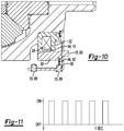
- the non-contacting position sensor 89 detects an axial position of the plunger 30 or a target 96 affixed to the plunger 30. As shown in Fig. 10 , the retention ring 82 may be the target 96.
- the retention ring 82 may be a double wound laminar ring.
- An example of a suitable retention ring 82 is a Spirolox® part number WS-587 available from Smalley Steel Ring Company, Lake Zurich, Illinois.
- the double wound laminar ring does not have a gap along the circumference that could cause a magnetic disturbance that could be misinterpreted as axial movement of the plunger 30 by a magnetic position detector.
- the target 96 may be magnetically responsive to be detectable by the non-contacting position sensor 89.
- the retention ring 82 may be formed from a magnetically responsive low carbon steel.
- Fig. 10 shows three alternative locations for the non-contacting position sensor 89.
- the non-contacting position sensor 89 may be disposed in any single location shown in Fig. 10 , or any combination of a plurality of the non-contacting position sensors 89 may be used for redundancy.
- an electrical switch 17 may be disposed on the vehicle 70 to selectably close a circuit 23 to provide electrical power to the solenoid 28.
- the switch 17 shown in Fig. 1 is a rocker switch, however any switch capable of controlling the flow of power through the solenoid 28 may be used.
- the switch 17 may be a low current switch that controls a relay or transistor that directly controls power through the solenoid 28.
- An electronic status indicator 29 may be disposed in the vehicle 70.
- An electronic driver circuit 25 may be disposed on the vehicle 70 to power the electronic status indicator 29 to indicate a status of the locking differential system 11. In an example, the status may include at least three states.
- the electronic status indicator 29 may be a selectably illuminated indicator 88, and the status may be indicated by a flash code.
- the selectably illuminated indicator 88 may include a light emitting diode, incandescent lamp, fluorescent lamp, or other selectably illuminatable light source.
- An example of a flash code may be as follows: the first state is indicated by not illuminating the electronic status indicator 29; the second state is indicated by continuously illuminating the electronic status indicator 29; and the third state is indicated by sequentially illuminating and not illuminating the electronic status indicator 29 with about a 50 percent duty cycle at a frequency between 1 and 20 hertz.
- Fig. 11 depicts a 50 percent duty cycle at a frequency of about 3 hertz.
- "On” means the electronic status indicator 29 is illuminated
- "Off” means the electronic status indicator 29 is not illuminated.
- States other than the three states in the example above, for example, error conditions may be indicated by predetermined sequences of illuminating and not illuminating the electronic status indicator 29.
- An electronic diagnostic system (not shown) may be connected to the locking differential system 11 to determine if error conditions exist.
- the status is selected from the group consisting of a first state, a second state, and a third state.
- the first state is a disengaged state having the electrical switch 17 in an open condition disconnecting power to the solenoid 28, and the lock ring 40 is in the disengaged position.
- the second state is an engaged state having the electrical switch 17 in a closed condition connecting power to the solenoid 28, and the lock ring 40 is in the engaged position.
- the third state is a transition state having the electrical switch 17 in an open condition disconnecting power to the solenoid 28, and the lock ring 40 is in the engaged position (see Fig.
- connection and/or the like are broadly defined herein to encompass a variety of divergent connected arrangements and assembly techniques. These arrangements and techniques include, but are not limited to (1) the direct communication between one component and another component with no intervening components therebetween; and (2) the communication of one component and another component with one or more components therebetween, provided that the one component being “connected to” the other component is somehow in operative communication with the other component (notwithstanding the presence of one or more additional components therebetween).
- ranges provided herein include the stated range and any value or sub-range within the stated range.
- a range from about 28 degrees to about 32 degrees should be interpreted to include not only the explicitly recited limits of about 28 degrees and about 32 degrees, but also to include individual values, such as 29 degrees, 30 degrees, 31 degrees, etc., and sub-ranges, such as from about 28 degrees to about 31 degrees, etc.
- “about” is utilized to describe a value, this is meant to encompass minor variations (up to +/-10%) from the stated value.
Landscapes
- Engineering & Computer Science (AREA)
- General Engineering & Computer Science (AREA)
- Mechanical Engineering (AREA)
- Physics & Mathematics (AREA)
- Electromagnetism (AREA)
- Chemical & Material Sciences (AREA)
- Combustion & Propulsion (AREA)
- Transportation (AREA)
- Retarders (AREA)
Description
- A locking differential may have an additional capability compared to a conventional "open" automotive differential. A vehicle with a locking differential may experience increased use of traction at the drive wheels compared to a vehicle with an "open" differential. Use of traction may be increased by restricting each of the two drive wheels on an axle to the same rotational speed without regard to the available traction or the road path taken at each wheel. The locking differential causes both wheels on an axle to turn together as if on a common axle shaft.
- An open differential, or unlocked locking differential allows each wheel on an axle to rotate at different speeds. When a vehicle negotiates a turn, the wheel on the smaller (inner) radius rotates more slowly than the wheel on the larger (outer) radius. Without the unlocked or open differential, one of the tires may scuff in a turn. With an open differential, when one wheel of an axle is on a slippery road surface, the wheel on the slippery surface may tend to spin while the other wheel may not have enough torque applied to it to move the vehicle. For example, some vehicles with open differentials may be unable to climb a hill with wet ice under one of the wheels no matter how dry the pavement is under the other wheel (this may be known as a split-mu surface).
- In contrast, a locked differential forces wheels on both sides of the same axle to rotate together at the same speed. Therefore, each wheel can apply as much torque as the wheel/road traction and the powertrain capacity will allow. In the example of the vehicle on the hill with the split-mu surface, a locked differential may allow the vehicle to climb the hill that is impossible for an otherwise identical vehicle to climb with an open differential. Locking differentials may also provide better traction that leads to improved vehicle performance under certain conditions, for example in drag racing, or snow plow operations.
- Some vehicles have differentials that may be reconfigured from an unlocked state to a locked state. Such vehicles may be operated with the differential in the unlocked state for normal conditions, for example, to prevent tire scuffing in turns, and reconfigured for operation with a locked differential when wheel slippage is encountered.
- In
JP 2011 033117 A claim 1. - The present invention is a locking differential assembly as it is defined in
claim 1. The locking differential assembly includes a differential case defining an axis of rotation and a gear chamber. A first side gear is at a first end of the differential case for selectable rotation relative thereto. A second side gear is at a second end of the differential case opposite the first end for selectable rotation relative to the differential case. At least two pinion gears are rotatably supported in the gear chamber in meshing engagement with the first side gear and the second side gear. A solenoid is at the first end. A plunger is selectably magnetically actuatable by the solenoid. A lock ring is selectably engagable with the second side gear to selectably prevent the side gear from rotating relative to the differential case. At least two relay rods are each connected to the plunger and to the lock ring to cause the lock ring to remain a fixed predetermined distance from the plunger. - Preferred embodiments of the locking differential assembly are defined in
dependent claims 2 to11. In the embodiment of the locking differential assembly defined inclaim 6, the plurality of lugs preferably is a quantity of nine lugs and the quantity of relay rods is three. - The present invention further is a locking differential system as it is defined in
claim 12. Preferred embodiments of the locking differential system are defined independent claims 13 to 18. In the embodiment of the locking differential system defined inclaim 18, the non-contacting position sensor optionally is a Hall-Effect position sensor. - Features and advantages of examples of the present disclosure will become apparent by reference to the following detailed description and drawings, in which like reference numerals correspond to the same or similar, though perhaps not identical, components. For the sake of brevity, reference numerals or features having a previously described function may or may not be described in connection with other drawings in which they appear.
-
Fig. 1 is a schematic view of a vehicle with a locking differential system according to an example of the present disclosure; -
Fig. 2 is a perspective view of a locking differential according to an example of the present disclosure; -
Fig. 3A is a cross-sectional perspective view of the locking differential depicted inFig. 2 ; -
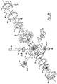
Fig. 3B is an exploded view of the locking differential depicted inFig. 2 ; -
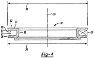
Fig. 4 is a cross-sectional side view of an example of a stator according to the present disclosure; -
Fig. 5A is a cross-sectional side view of an example of a plunger according to the present disclosure; -
Fig. 5B is an exploded side view of an example of a plunger and a relay rod according to the present disclosure; -
Fig. 6A is a plan view of an example of a lock ring according to the present disclosure; -
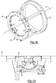
Fig. 6B is a perspective view of an example of a locking differential with an end cover removed according to the present disclosure; -
Fig. 6C is a perspective view of an example of a lock ring, relay rods and a plunger assembled as in the locking differential depicted inFig. 2 ; -
Fig. 7A is a cross-sectional view of an example of the differential assembly with the lock ring in the disengaged position according to the present disclosure; -
Fig. 7B is a cross-sectional view of an example of the differential assembly with the lock ring in the engaged position according to the present disclosure; -
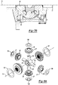
Fig. 8A is a partially exploded perspective view of a differential gear set according to the present disclosure; -
Fig. 8B is an exploded perspective view of an example of a cross shaft according to the present disclosure; -
Fig. 9 is an exploded perspective view of another example of a cross shaft according to the present disclosure; -
Fig. 10 is an enlarged cross-sectional view of an example of a stator, plunger, and position sensor according to the present disclosure; and -
Fig. 11 is time graph depicting an example of a flash code according to the present disclosure. - The present disclosure relates generally to locking differentials, and more particularly to electronically controlled locking differentials used in vehicle drive axles. As used herein, an electronically controlled locking differential means a differential that changes between an unlocked state and a locked state in response to an electronic signal. In the locked state, both axle shafts connected to the differential rotate together in the same direction, at the same speed. The electronic signal may be automatically produced in response to a vehicle condition, for example, detection of wheel slippage. The electronic signal may also be produced in response to a demand from an operator, for example, an operator may press a button on a control panel of the vehicle.
- Examples of the present disclosure may allow the differentials to operate at a higher torque than similarly sized existing locking differentials. The time to actuate the locking mechanism may also be reduced compared to existing electronic locking differentials. Further, the status indicator may provide a more satisfactory user experience by providing more detailed and accurate information regarding the operation of the electronically controlled locking differential system of the present disclosure.
- Referring to
Fig. 1 , apowertrain 5 for avehicle 70 includes amotor 6, a propeller shaft 7 connected to the motor and anaxle assembly 8. The propeller shaft 7 is connected, for example, by gearing (not shown) to rotationally drive theaxle shafts 13, 13' inside theaxle housing 9. Theaxle assembly 8 includes theaxle housing 9, a lockingdifferential assembly 10 supported inaxle housing 9 and theaxle shafts 13, 13' respectively connected to first andsecond drive wheels 98 and 98'. Agearset 97 disposed within adifferential case 12 transfers rotational power fromdifferential case 12 to theaxle shafts 13, 13', and selectably allows relative rotation between theaxle shafts 13 and 13'. Although the lockingdifferential assembly 10 depicted inFig. 1 is applied to a rear-wheel drive vehicle, the present disclosure may be used in transaxles for use in front-wheel drive vehicles, transfer cases for use in four-wheel drive vehicles or in any vehicle powertrain. - Referring to
Figs. 2, 3A and3B together, an example of the present disclosure is depicted including a lockingdifferential assembly 10. The lockingdifferential assembly 10 has adifferential case 12 defining an axis ofrotation 14 and agear chamber 16. Thedifferential case 12 rotates in the axle housing 9 (seeFig. 1 ) about the axis ofrotation 14. Afirst side gear 18 is disposed at afirst end 19 of thedifferential case 12 for selectable relative rotation thereto. Asecond side gear 20 is disposed at asecond end 21 of thedifferential case 12 opposite thefirst end 19 for selectable rotation relative to thedifferential case 12. - The
second side gear 20 has side gear dogs 22 defined on anoutside diameter 24 of thesecond side gear 20 parallel to the axis ofrotation 14. At least two pinion gears 26 are rotatably supported in thegear chamber 16. Each of the at least two pinion gears 26 is in meshing engagement with thefirst side gear 18 and thesecond side gear 20. - The locking
differential assembly 10 includes asolenoid 28, disposed at thefirst end 19 of thedifferential case 12. Thestator 32 is formed from a ferromagnetic material. Thedifferential case 12 is rotatable relative to thestator 32 about the axis ofrotation 14. As depicted inFig. 4 , thestator 32 has anannular wall 33 with alongitudinal axis 35 coaxial with the axis ofrotation 14. Although theannular wall 33 depicted inFig. 4 is a cylindrical wall, and thelongitudinal axis 35 is a cylindrical axis, theannular wall 33 may deviate from a cylindrical shape in examples of the present disclosure. Theannular wall 33 may, for example, have a larger diameter at one or both ends, or theannular wall 33 may have an arcuate section. A first statorannular flange 36 extends radially from theannular wall 33 to a firstouter diameter 38 of the first statorannular flange 36. AlthoughFig. 4 depicts the first statorannular flange 36 extending perpendicularly to thelongitudinal axis 35, the angle that theannular flange 36 makes with thelongitudinal axis 35 may deviate from 90 degrees. For example, the angle may be 45 degrees such that the bobbin is wider at the firstouter diameter 38 than at an interface between the first statorannular flange 36 and theannular wall 33. The angle between the first statorannular flange 36 and theannular wall 33 may be any angle. - A second stator
annular flange 37 extends from theannular wall 33. The second statorannular flange 37 is spaced from the first statorannular flange 36 and may be parallel to the first statorannular flange 36. The second statorannular flange 37 is frustoconical with an inner baseannular surface 51 opposite the first statorannular flange 36. An outer baseannular surface 52 is distal to the first statorannular flange 36. The inner baseannular surface 51 has an outer edge diameter 53 equal to the firstouter diameter 38. The outer baseannular surface 52 has a secondouter diameter 39 greater than the firstouter diameter 38. The first statorannular flange 36, theannular wall 33 and the second statorannular flange 37 together define anintegral bobbin 31 for thesolenoid 28. AlthoughFig. 4 depicts the integral bobbin having a substantially rectangular cross section, the surfaces may be rounded or canted in examples of the present disclosure. Thesolenoid 28 is directly wound onto thestator 32. Directly winding thesolenoid 28 onto thestator 32 is facilitated by having theintegral bobbin 31 open between the firstouter diameter 38 and the secondouter diameter 39. Thestator 32 with theintegral bobbin 31 of the present disclosure differs from other stators that open axially. A stator that opens axially may require that the solenoid be wound on a separate bobbin and slid into the axial opening. The space required for the separate bobbin is space that is not available for solenoid windings. Even if a so-called bobbinless coil is used, the additional manufacturing steps required to create the separate coil and then install the coil into the stator may be less desirable than thestator 32 with theintegral bobbin 31 of the present disclosure. -
Fig. 3B depicts aspring 34 disposed between thedifferential case 12 and thelock ring 40 to bias thelock ring 40 toward the disengaged position. Acover 100 is shown at thesecond end 21 of the lockingdifferential assembly 10. A side gear thrustwasher 101 is disposed between thecover 100 and thesecond side gear 20. Another side gear thrustwasher 101 is disposed between thedifferential case 12 and thefirst side gear 18. Thrustwashers 104 are disposed between the pinion gears 26 and thedifferential case 12. Shaft anchor roll pins 103 are inserted through thedifferential case 12 and the cross-shaft 90 and thestub shafts 92 to retain the cross-shaft 90 andstub shafts 92 for supporting the pinion gears 26.Stator retaining ring 102 is inserted into a groove in thedifferential case 12 to prevent the stator from moving axially relative to thedifferential case 12. - Referring to
Figs. 5A and 5B , in examples of the present disclosure, aplunger 30 is selectably magnetically actuated by the solenoid 28 (seeFig. 3A ). Theplunger 30 has a ferromagneticcylindrical body 54. The ferromagneticcylindrical body 54 has acylindrical body axis 55 defined by the ferromagneticcylindrical body 54 to be aligned with the axis ofrotation 14. The ferromagneticcylindrical body 54 has aninner wall 56 with anannular bevel 57 at abeveled end 58 of the ferromagneticcylindrical body 54. The ferromagneticcylindrical body 54 further includes anouter wall 59 having a plungerouter diameter 61. Anannular plunger flange 62 is defined at aplunger end 63 distal to thebeveled end 58. Theannular plunger flange 62 has aplunger flange diameter 64 smaller than the plungerouter diameter 61. Anannular notch 65 is defined by the ferromagneticcylindrical body 54 and theannular plunger flange 62. - In an example, the
plunger 30 is fixed for rotation with thedifferential case 12, and theplunger 30 is selectably translatable relative to thedifferential case 12 along the axis of rotation 14 (seeFigs. 2, 3A ,7A and7B ). The rotatingplunger 30 rotates relative to thestator 32. Contact between theplunger 30 and thestator 32 may lead to galling of theplunger 30, thestator 32 or both. - Referring back to
Figs. 5A and 5B , in examples of the present disclosure, the lockingdifferential assembly 10 may include aspacer 60, 60' disposed between theplunger 30 and thedifferential case 12 to prevent theannular bevel 57 of theinner wall 56 from contacting the second statorannular flange 37. In an example, thespacer 60 may be a threadedrod 71 adjustably screwed into theplunger 30 to set a predetermined gap 72 (seeFig. 7B ) between theannular bevel 57 and the second statorannular flange 37. In another example, the spacer 60' may be a plurality of spaced raised bosses on thebeveled end 58 of the ferromagneticcylindrical body 54. - A plurality of relay rod attachment bores 66 are defined in the ferromagnetic
cylindrical body 54. A plurality 67 of relay rod access slots 69 are each defined in thebeveled end 58 of the ferromagneticcylindrical body 54 at each relay rod attachment bore 68. Each relay rod attachment bore 68 is substantially centered in the respective relay rod access slot 69. A shortest distance between the relay rod access slot 69 and theannular notch 65 is equal to thelock ring thickness 41. Such equality of dimensions allows each of therelay rods 50 to have end-to-end symmetry. - At least two
relay rods 50 are each connected to theplunger 30 and to thelock ring 40 to cause the lock ring 40 (seeFig. 6C ) to remain a fixed predetermined distance from theplunger 30. - The at least two
relay rods 50 each include acylindrical rod portion 74 having two ends 77, thecylindrical rod portion 74 defining alongitudinal rod axis 75 at acenter 76 of thecylindrical rod portion 74. Therelay rods 50 each have afirst post 78 and asecond post 79 each having asmaller diameter 80 than thecylindrical rod portion 74 defined at a respective one of the two ends 77. Thefirst post 78 and thesecond post 79 are each concentric with thecylindrical rod portion 74. Anannular groove 81 is defined on thefirst post 78 and thesecond post 79. Thefirst post 78 and thesecond post 79 are substantially identical, and therelay rod 50 is symmetrical end-to-end. In other words, during assembly, therelay rods 50 may be installed without regard to which end is installed in theplunger 30 and which end is installed in thelock ring 40. InFig. 5B , thefirst post 78 and thesecond post 79 are given different reference numbers for clarity in describingFig. 5B , however, thefirst post 78 is identical to thesecond post 79. Thefirst post 78 is depicted as being retained in a respective relay rod attachment bore 68 by aretention ring 82 disposed in theannular notch 65 of theplunger 30 protruding into theannular groove 81 of thefirst post 78. - Referring now to
Figs. 6A, 6B , and6C together, in examples of the present disclosure, the lockingdifferential assembly 10 has alock ring 40. Thelock ring 40 includescomplementary dogs 42 defined around aninside surface 43 of thelock ring 40. Thecomplementary dogs 42 are selectably engagable with the side gear dogs 22 by translating thelock ring 40 along the axis ofrotation 14 from a disengaged position to an engaged position. Thelock ring 40 has a plurality oflugs 46 defined on anoutside surface 47 of thelock ring 40. Eachlug 48 is to slide in a respectivecomplementary slot 49 defined in thedifferential case 12 to guide the translation of thelock ring 40 between the engaged position and the disengaged position. (SeeFigs. 7A and7B .) The fit of the plurality oflugs 46 in the respectivecomplementary slots 49 also prevents rotation of thelock ring 40 relative to thedifferential case 12. -
Fig. 7A depicts an example of the present disclosure with thelock ring 40 in the disengaged position.Fig. 7B depicts the example shown inFig. 7A except the thelock ring 40 is in the engaged position. In examples of the present disclosure, thesecond side gear 20 is substantially prevented from rotating relative to thedifferential case 12 when thelock ring 40 is in the engaged position. Thesecond side gear 20 is free to rotate relative to thedifferential case 12 when thelock ring 40 is in the disengaged position. Thelock ring 40 has alock ring thickness 41 parallel to the axis ofrotation 14. - The
lock ring 40 further includesextension tabs 83 on a quantity of thelugs 48 equal to a quantity of therelay rods 50. Theextension tabs 83 each define a relayrod attachment hole 84. Eachrelay rod 50 is retained in the respective relayrod attachment hole 84 by aclip 85 installed in theannular groove 81 of the respective second post 79 (seeFig. 5B for detail of annular groove 81). In an example, the plurality oflugs 46 is a quantity of ninelugs 48, and the quantity ofrelay rods 50 is three. - Each
lug 48 may have two opposed faces 86 symmetrically arranged about aradial line 87 perpendicular to the axis ofrotation 14. An angle 99 between the two opposed faces 86 is from about 28 degrees to about 32 degrees. - Referring now to
Figs. 8A and8B , examples of the present disclosure may have a cross-shaft 90 disposed perpendicularly to the axis ofrotation 14 of thedifferential case 12 to support anopposed pair 27 of the at least two pinion gears 26 for rotation of the opposedpair 27 of the at least two pinion gears 26 on the cross-shaft 90. In examples of the present disclosure with a 4-pinion differential, thedifferential assembly 10 may include a pair ofopposed stub shafts 92, eachstub shaft 92 being disposed perpendicularly to the cross-shaft 90 and perpendicularly to the axis ofrotation 14 of thedifferential case 12 through ayoke 91. Theyoke 91 is disposed around the cross-shaft 90. Theyoke 91 hascomplementary apertures 93 for receiving thestub shafts 92. The pair ofopposed stub shafts 92 support another opposed pair 27' of the at least two pinion gears 26. - In the example depicted in
Fig. 9 , the cross-shaft 90' may include two opposedcentral grooves 4. Each of the opposedcentral grooves 4 is to receive a complementary tongue disposed on the stub shaft 92'. Examples having the tongue in groove joints depicted inFig. 9 may or may not include theyoke 91 shown inFig. 8B . - Examples of the present disclosure may include a locking
differential system 11 that includes the lockingdifferential assembly 10 with thesolenoid 28 directly wound on thestator 32 as described above, with control elements described below. The lockingdifferential system 11 may include a plunger position sensor 15 to determine a state of thelock ring 40 by detecting the position of theplunger 30. In an example of a plunger position sensor 15, a secondary coil 94 may be wound around thestator 32 to detect an inductance in thesolenoid 28 responsive to a position of theplunger 30. As shown inFig. 10 , in another example, the plunger position sensor 15 may be anon-contacting position sensor 89 disposed on ananti-rotation bracket 95 connected to thestator 32. In examples of the present disclosure, the non-contacting position sensor 15 may use any non-contacting position sensor technology. For example, non-contacting postion sensors based on magnetostriction, magnetoresistance, Hall-Effect, or other magnetic sensing technologies may be included in the lockingdifferential system 11 according to the present disclosure. Further, non-contacting position sensors based on optical, infrared, or fluid pressure sensing may also be used according to the present disclosure. In the example, thenon-contacting position sensor 89 detects an axial position of theplunger 30 or atarget 96 affixed to theplunger 30. As shown inFig. 10 , theretention ring 82 may be thetarget 96. In examples having theretention ring 82 also operative as thetarget 96, theretention ring 82 may be a double wound laminar ring. An example of asuitable retention ring 82 is a Spirolox® part number WS-587 available from Smalley Steel Ring Company, Lake Zurich, Illinois. The double wound laminar ring does not have a gap along the circumference that could cause a magnetic disturbance that could be misinterpreted as axial movement of theplunger 30 by a magnetic position detector. Thetarget 96 may be magnetically responsive to be detectable by thenon-contacting position sensor 89. Theretention ring 82 may be formed from a magnetically responsive low carbon steel.Fig. 10 shows three alternative locations for thenon-contacting position sensor 89. Thenon-contacting position sensor 89 may be disposed in any single location shown inFig. 10 , or any combination of a plurality of thenon-contacting position sensors 89 may be used for redundancy. - Returning back to
Fig. 1 , anelectrical switch 17 may be disposed on thevehicle 70 to selectably close acircuit 23 to provide electrical power to thesolenoid 28. Theswitch 17 shown inFig. 1 is a rocker switch, however any switch capable of controlling the flow of power through thesolenoid 28 may be used. Theswitch 17 may be a low current switch that controls a relay or transistor that directly controls power through thesolenoid 28. An electronic status indicator 29 may be disposed in thevehicle 70. Anelectronic driver circuit 25 may be disposed on thevehicle 70 to power the electronic status indicator 29 to indicate a status of the lockingdifferential system 11. In an example, the status may include at least three states. For example, the electronic status indicator 29 may be a selectably illuminated indicator 88, and the status may be indicated by a flash code. To illustrate, the selectably illuminated indicator 88 may include a light emitting diode, incandescent lamp, fluorescent lamp, or other selectably illuminatable light source. - An example of a flash code may be as follows: the first state is indicated by not illuminating the electronic status indicator 29; the second state is indicated by continuously illuminating the electronic status indicator 29; and the third state is indicated by sequentially illuminating and not illuminating the electronic status indicator 29 with about a 50 percent duty cycle at a frequency between 1 and 20 hertz.
Fig. 11 depicts a 50 percent duty cycle at a frequency of about 3 hertz. InFig. 11 , "On" means the electronic status indicator 29 is illuminated, and "Off" means the electronic status indicator 29 is not illuminated. States other than the three states in the example above, for example, error conditions, may be indicated by predetermined sequences of illuminating and not illuminating the electronic status indicator 29. An electronic diagnostic system (not shown) may be connected to the lockingdifferential system 11 to determine if error conditions exist. - In an example, the status is selected from the group consisting of a first state, a second state, and a third state. In the example, the first state is a disengaged state having the
electrical switch 17 in an open condition disconnecting power to thesolenoid 28, and thelock ring 40 is in the disengaged position. The second state is an engaged state having theelectrical switch 17 in a closed condition connecting power to thesolenoid 28, and thelock ring 40 is in the engaged position. The third state is a transition state having theelectrical switch 17 in an open condition disconnecting power to thesolenoid 28, and thelock ring 40 is in the engaged position (seeFig. 7B ); or theelectrical switch 17 is in a closed condition connecting power to thesolenoid 28, and thelock ring 40 is in the disengaged position (seeFig. 7A ). The inventors of the present disclosure believe that indicating the transition state will reduce a tendency for an operator to continue to press a differential lock control button, or press the button harder, while the lockingdifferential system 11 is in the transition state. - It is to be understood that the terms "connect/connected/connection" and/or the like are broadly defined herein to encompass a variety of divergent connected arrangements and assembly techniques. These arrangements and techniques include, but are not limited to (1) the direct communication between one component and another component with no intervening components therebetween; and (2) the communication of one component and another component with one or more components therebetween, provided that the one component being "connected to" the other component is somehow in operative communication with the other component (notwithstanding the presence of one or more additional components therebetween).
- In describing and claiming the examples disclosed herein, the singular forms "a", "an", and "the" include plural referents unless the context clearly dictates otherwise.
- It is to be understood that the ranges provided herein include the stated range and any value or sub-range within the stated range. For example, a range from about 28 degrees to about 32 degrees should be interpreted to include not only the explicitly recited limits of about 28 degrees and about 32 degrees, but also to include individual values, such as 29 degrees, 30 degrees, 31 degrees, etc., and sub-ranges, such as from about 28 degrees to about 31 degrees, etc. Furthermore, when "about" is utilized to describe a value, this is meant to encompass minor variations (up to +/-10%) from the stated value.
- Furthermore, reference throughout the specification to "one example", "another example", "an example", and so forth, means that a particular element (e.g., feature, structure, and/or characteristic) described in connection with the example is included in at least one example described herein, and may or may not be present in other examples. In addition, it is to be understood that the described elements for any example may be combined in any suitable manner in the various examples unless the context clearly dictates otherwise.
- While several examples have been described in detail, it will be apparent to those skilled in the art that the disclosed examples may be modified. Therefore, the foregoing description is to be considered non-limiting.
Claims (18)
- A locking differential assembly (10), comprising:a differential case (12) defining an axis of rotation (14) and a gear chamber (16);a first side gear (18) disposed at a first end (19) of the differential case (12) for selectable relative rotation thereto;a second side gear (20) disposed at a second end (21) of the differential case (12) opposite the first end (19) for selectable rotation relative to the differential case (12);at least two pinion gears (26) rotatably supported in the gear chamber (16) , each of the at least two pinion gears (26) being in meshing engagement with the first side gear (18) and the second side gear (20);a solenoid (28) disposed at the first end (19);a plunger (30) selectably magnetically actuatable by the solenoid (28);a lock ring (40) selectably engagable with the second side gear (20) to selectably prevent the second side gear (20) from rotating relative to the differential case (12); andat least two relay rods (50) each connected to the plunger (30) and to the lock ring (40) to cause the lock ring (40) to remain at a fixed predetermined distance from the plunger (30);characterized in that the locking differential assembly further comprises:side gear dogs (22) defined on an outside diameter (24) of the second side gear (20) parallel to the axis of rotation (14);complementary dogs (42) defined around an inside surface (43) of the lock ring (40), the complementary dogs (42) being selectably engagable with the side gear dogs (22) by translating the lock ring (40) along the axis of rotation (14) from a disengaged position to an engaged position ;a spring (34) disposed between the differential case (12) and the lock ring (40) to bias the lock ring (40) toward the disengaged position ; anda plurality of lugs (46) defined on an outside surface (47) of the lock ring (40), each lug (48) to slide in a respective complementary slot (49) defined in the differential case (12) to guide the lock ring (40) translation between the engaged position and the disengaged position and to prevent rotation of the lock ring (40) relative to the differential case (12);wherein the second side gear (20) is substantially prevented from rotating relative to the differential case (12) when the lock ring (40) is in the engaged position, and the second side gear (20) is free to rotate relative to the differential case (12) when the lock ring (40) is in the disengaged position and wherein the lock ring (40) has a lock ring thickness (41) parallel to the axis of rotation (14).
- The locking differential assembly (10) as defined in claim 1 wherein the solenoid (28) is directly wound onto a stator (32), the stator (32) comprising:an annular wall (33) having a longitudinal axis coaxial with the axis of rotation (14);a first stator annular flange (36) extending radially from the annular wall (33) to a first outer diameter (38); anda second stator annular flange (37) extending from the annular wall (33) spaced from the first stator annular flange (36) wherein the second stator annular flange (37) is frustoconical with an inner base annular surface (51) opposite the first stator annular flange (36) and an outer base annular surface (52) distal to the first stator annular flange (36), wherein the inner base annular surface (51) has an outer edge diameter (53) equal to the first outer diameter (38) and the outer base annular surface (52) has a second outer diameter (39) greater than the first outer diameter (38), wherein the first stator annular flange (36), the annular wall (33) and the second stator annular flange (37) define an integral bobbin for the solenoid (28), and wherein the stator (32) is formed from a ferromagnetic material, wherein the differential case (12) is rotatable relative to the stator (32) about the axis of rotation (14).
- The locking differential assembly (10) as defined in claim 2 wherein:the annular wall (33) is a cylindrical wall;the longitudinal axis is a cylindrical axis (35);the first stator annular flange (36) extends perpendicularly to the cylindrical axis (35) from the cylindrical wall;the second stator annular flange (37) extends from the cylindrical wall spaced from the first stator annular flange (36) and parallel to the first stator annular flange (36); andthe first stator annular flange (36), the cylindrical wall and the second stator annular flange (37) define the integral bobbin.
- The locking differential assembly (10) as defined in claim 2 wherein the plunger (30) comprises:a ferromagnetic cylindrical body (54), including:a cylindrical body axis (55) defined by the ferromagnetic cylindrical body (54) to be aligned with the axis of rotation (14);an inner wall (56) having an annular bevel (57) at a beveled end (58) of the ferromagnetic cylindrical body (54);an outer wall (59) having a plunger outer diameter (61); andan annular plunger flange (62) defined at a plunger end (63) distal to the beveled end (58) wherein the annular plunger flange (62) has a plunger flange diameter (64) smaller than the plunger outer diameter (61);an annular notch (65) defined by the ferromagnetic cylindrical body (54) and the annular plunger flange (62);a plurality of relay rod attachment bores (66) defined in the ferromagnetic cylindrical body (54); anda plurality of relay rod access slots (67) each defined in the beveled end (58) of the ferromagnetic cylindrical body (54) at each relay rod attachment bore (68), wherein the relay rod attachment bore (68) is substantially centered in the relay rod access slot (69), wherein a shortest distance between the relay rod access slot (69) and the annular notch (65) is equal to the lock ring thickness (41).
- The locking differential assembly (10) as defined in claim 4, further comprising:a spacer (60) disposed between the plunger (30) and the differential case (12) to prevent the annular bevel (57) of the inner wall (56) from contacting the second stator annular flange (37), wherein optionally the spacer (60) is:(a) a threaded rod (71) adjustably screwed into the plunger (30) to set a predetermined gap (72) between the annular bevel (57) and the second stator annular flange (37), or(b) a plurality of spaced raised bosses on the beveled end (58) of the ferromagnetic cylindrical body (54).
- The locking differential assembly (10) as defined in claim 4, the at least two relay rods each comprising:a cylindrical rod portion (74) having two ends, the cylindrical rod portion (74) defining a longitudinal rod axis (75) at a center (76) of the cylindrical rod portion (74);a first post (78) and a second post (79) each having a smaller diameter (80) than the cylindrical rod portion (74) defined at a respective one of the two ends,the first post (78) and the second post (79) each being concentric with the cylindrical rod portion (74); andan annular groove (81) defined on the first post (78) and the second post (79), wherein the first and second posts are substantially identical and the relay rod is symmetrical end-to-end, wherein the first post (78) is retained in a respective relay rod attachment bore (68) by a retention ring (82) disposed in the annular notch (65) of the plunger (30) protruding into the annular groove (81) of the first post (78),wherein the lock ring (40) further includes extension tabs (83) on a quantity of the lugs equal to a quantity of the relay rods, the extension tabs (83) each having a relay rod attachment hole (84) therethrough wherein each relay rod is retained in the respective relay rod attachment hole (84) by a clip (85) installed in the annular groove (81) of the respective second post (79).
- The locking differential assembly (10) as defined in claim 1 wherein:the plunger (30) is fixed for rotation with the differential case (12); andthe plunger (30) is selectably translatable relative to the differential case (12) along the axis of rotation (14).
- The locking differential assembly (10) as defined in claim 1 wherein:each lug (48) has two opposed faces (86) symmetrically arranged about a radial line (87) perpendicular to the axis of rotation (14); andan angle (99) between the two opposed faces (86) is from about 28 degrees to about 32 degrees.
- The locking differential assembly (10) as defined in claim 8 wherein the plurality of lugs (46) is a quantity of nine lugs.
- The locking differential assembly (10) as defined in claim 1, further comprising:a cross-shaft (90) disposed perpendicularly to the axis of rotation (14) of the differential case (12) to support an opposed pair (27) of the at least two pinion gears (26) for rotation of the opposed pair (27) of the at least two pinion gears (26) on the cross-shaft (90).
- The locking differential assembly (10) as defined in claim 10, further comprising:a pair of opposed stub shafts (92) disposed perpendicularly to the cross-shaft (90) and perpendicularly to the axis of rotation (14) of the differential case (12) through a yoke (91), wherein:the yoke (91) is disposed around the cross-shaft (90);the yoke (91) has complementary apertures (93) for receiving the stub shafts; andthe pair of opposed stub shafts (92) support an other opposed pair of the at least two pinion gears (26).
- A locking differential system (11), comprising:the locking differential assembly (10) as defined in claim 1;a plunger position sensor (15) to determine a state of the lock ring (40) by detecting a position of the plunger (30);an electrical switch (17) to selectably close a circuit (23) to provide electrical power to the solenoid (28);an electronic status indicator (29); andan electronic driver circuit (25) for powering the electronic status indicator (29) to indicate a status of the locking differential system (11) wherein the status includes at least three states.
- The locking differential system (11) as defined in claim 12 wherein the electronic status indicator (29) is a selectably illuminated indicator (88) and the status is indicated by a flash code.
- The locking differential system (11) as defined in claim 12 wherein:the status is selected from the group consisting of a first state, a second state, and a third state;the first state is a disengaged state having the electrical switch (17) in an open condition to disconnect power to the solenoid (28) and the lock ring (40) is in the disengaged position ;the second state is an engaged state having the electrical switch (17) in a closed condition connecting power to the solenoid (28) and the lock ring (40) is in the engaged position ; andthe third state is a transition state having the electrical switch (17) in an open condition disconnecting power to the solenoid (28) and the lock ring (40) is in the engaged position or the electrical switch (17) is in a closed condition connecting power to the solenoid (28) and the lock ring (40) is in the disengaged position.
- The locking differential system (11) as defined in claim 12 wherein:the electronic status indicator (29) is a selectably illuminated indicator (88);the at least three states include a first state, a second state, and a third state;the first state is indicated by not illuminating the electronic status indicator (29);the second state is indicated by continuously illuminating the electronic status indicator (29); andthe third state is indicated by sequentially illuminating and not illuminating the electronic status indicator (29) with about a 50 percent duty cycle at a frequency between 1 hertz and 20 hertz.
- The locking differential system (11) as defined in claim 12, further comprising:a stator (32) having the solenoid (28) directly wound thereon, the stator (32) including:an annular wall (33) having a longitudinal axis coaxial with the axis of rotation (14);a first stator annular flange (36) extending radially from the annular wall (33) to a first outer diameter (38); anda second stator annular flange (37) extending from the annular wall (33) spaced from the first stator annular flange (36) and parallel to the first stator annular flange (36), wherein the second stator annular flange (37) is frustoconical with an inner base annular surface (51) opposite the first stator annular flange (36) and an outer base annular surface (52) distal to the first stator annular flange (36), wherein the inner base annular surface (51) has an outer edge diameter (53) equal to the first outer diameter (38) and the outer base annular surface (52) has a second outer diameter (39) greater than the first outer diameter (38), wherein the first stator annular flange (36), the annular wall (33) and the second stator annular flange (37) define an integral bobbin for the solenoid (28) and wherein the stator (32) is formed from a ferromagnetic material, wherein the differential case (12) is rotatable relative to the stator (32) about the axis of rotation (14); anda secondary coil (94) wound around the stator (32) to detect an inductance in the solenoid (28) responsive to a position of the plunger (30).
- The locking differential system (11) as defined in claim 16 wherein:the annular wall (33) is a cylindrical wall;the longitudinal axis is a cylindrical axis (35);the first stator annular flange (36) extends perpendicularly to the cylindrical axis (35) from the cylindrical wall;the second stator annular flange (37) extends from the cylindrical wall spaced from the first stator annular flange (36) and parallel to the first stator annular flange (36); andthe first stator annular flange (36), the cylindrical wall and the second stator annular flange (37) define the integral bobbin.
- The locking differential system (11) as defined in claim 12, further comprising:a stator (32) with the solenoid (28) directly wound thereon; anda non-contacting position sensor disposed on an anti-rotation bracket (95) connected to the stator (32), wherein the non-contacting position sensor is to detect an axial position of the plunger (30) or a target (96) affixed to the plunger (30).
Applications Claiming Priority (2)
| Application Number | Priority Date | Filing Date | Title |
|---|---|---|---|
| US201361755939P | 2013-01-23 | 2013-01-23 | |
| PCT/US2014/012702 WO2014116802A1 (en) | 2013-01-23 | 2014-01-23 | Locking differential assembly |
Publications (3)
| Publication Number | Publication Date |
|---|---|
| EP2855188A1 EP2855188A1 (en) | 2015-04-08 |
| EP2855188A4 EP2855188A4 (en) | 2015-12-30 |
| EP2855188B1 true EP2855188B1 (en) | 2017-03-01 |
Family
ID=51228023
Family Applications (1)
| Application Number | Title | Priority Date | Filing Date |
|---|---|---|---|
| EP14743310.6A Active EP2855188B1 (en) | 2013-01-23 | 2014-01-23 | Locking differential assembly |
Country Status (11)
| Country | Link |
|---|---|
| US (2) | US9625026B2 (en) |
| EP (1) | EP2855188B1 (en) |
| JP (1) | JP6376668B2 (en) |
| KR (1) | KR20150109251A (en) |
| CN (1) | CN104395126B (en) |
| AU (1) | AU2014209354B2 (en) |
| BR (1) | BR112014032424A2 (en) |
| IN (1) | IN2014DN10990A (en) |
| RU (1) | RU2661248C2 (en) |
| WO (1) | WO2014116802A1 (en) |
| ZA (1) | ZA201409214B (en) |
Families Citing this family (45)
| Publication number | Priority date | Publication date | Assignee | Title |
|---|---|---|---|---|
| USD749135S1 (en) * | 2013-09-09 | 2016-02-09 | Eaton Corporation | Electronic limited slip differential with separation of clutch and actuator |
| CN105960551B (en) * | 2013-11-26 | 2019-02-12 | Gkn汽车有限公司 | Differential including coupling assembly with target element |
| CA2887514C (en) * | 2014-04-09 | 2023-05-23 | TAP Worldwide, LLC | Locking differential |
| US9500268B2 (en) * | 2014-12-03 | 2016-11-22 | American Axle & Manufacturing, Inc. | Locking differential assembly |
| JP6493944B2 (en) | 2015-08-07 | 2019-04-03 | デーナ、オータモウティヴ、システィムズ、グループ、エルエルシー | Wireless system for determining the displacement of spinning components |
| WO2017100550A1 (en) * | 2015-12-11 | 2017-06-15 | Eaton Corporation | Locking differential assembly |
| US10119940B2 (en) * | 2016-08-25 | 2018-11-06 | The Boeing Company | Acoustic emission sensor holder |
| FR3055269B1 (en) * | 2016-08-26 | 2018-09-28 | Alstom Transp Tech | WARNING DEVICE FOR A URBAN PUBLIC TRANSPORT VEHICLE, IN PARTICULAR A TRAMWAY |
| DE112017004128T5 (en) * | 2016-09-20 | 2019-05-09 | Eaton Intelligent Power Limited | Locking differential arrangement |
| DE102016221722A1 (en) * | 2016-11-07 | 2018-05-09 | Zf Friedrichshafen Ag | Differential device and a vehicle with the differential device |
| USD900874S1 (en) * | 2016-11-17 | 2020-11-03 | Eaton Intelligent Power Limited | Differential case |
| US10352729B2 (en) * | 2017-02-01 | 2019-07-16 | GM Global Technology Operations LLC | System and method for using actuator coil inductance to diagnose stuck differential |
| US10113627B2 (en) * | 2017-02-02 | 2018-10-30 | American Axle & Manufacturing, Inc. | Differential assembly with multi-piece cross-pin |
| EP3593013B1 (en) * | 2017-03-03 | 2023-06-07 | Eaton Intelligent Power Limited | Electronically actuated locking differential having lock detection mechanism |
| US11499617B2 (en) | 2017-03-03 | 2022-11-15 | Eaton Intelligent Power Limited | Electronically actuated locking differential having lock detection mechanism |
| DE102017106665B4 (en) | 2017-03-28 | 2018-12-06 | Gkn Automotive Ltd. | Pin arrangement for a differential gear and differential gear with such a pin arrangement |
| US11142067B2 (en) | 2017-05-09 | 2021-10-12 | Dana Automotive Systems Group, Llc | Differential sensor apparatus and method of use |
| WO2019238272A1 (en) * | 2018-06-14 | 2019-12-19 | Eaton Intelligent Power Limited | Differential having armature position detection |
| US11396935B2 (en) | 2017-06-16 | 2022-07-26 | Eaton Intelligent Power Limited | Differential having armature position detection |
| JP2019027525A (en) * | 2017-07-31 | 2019-02-21 | 株式会社ジェイテクト | Differential device and method for adjusting differential device |
| US20190113082A1 (en) * | 2017-09-08 | 2019-04-18 | Kanzaki Kokyukoki Mfg. Co., Ltd. | Differential gear |
| TWI648492B (en) | 2017-10-20 | 2019-01-21 | 財團法人工業技術研究院 | Interferometric torque distribution differential |
| US11118665B2 (en) * | 2017-12-22 | 2021-09-14 | Dana Automotive Systems Group, Llc | Electrical differential locker with eddy current sensor |
| US10612637B2 (en) * | 2018-01-18 | 2020-04-07 | American Axle & Manufacturing, Inc. | Driveline component having differential assembly with differential gearset configured to limit inboard thrust of side gears |
| USD941880S1 (en) | 2018-01-19 | 2022-01-25 | Eaton Intelligent Power Limited | Differential case |
| DE112019000254T5 (en) * | 2018-01-20 | 2020-08-20 | Eaton Intelligent Power Limited | LOCKING DIFFERENTIAL ARRANGEMENT |
| CN108916352A (en) * | 2018-05-31 | 2018-11-30 | 汽解放汽车有限公司 | A kind of driven wheel of differential and differential mechanism left housing integrate structure |
| US10982750B2 (en) | 2018-10-01 | 2021-04-20 | Dana Automotive Systems Group, Llc | Retention system |
| US11005337B2 (en) | 2018-10-23 | 2021-05-11 | Atieva, Inc. | Removable differential for an active core electric motor |
| EP3877671B1 (en) * | 2018-11-05 | 2025-09-03 | Eaton Intelligent Power Limited | Direct acting electronic locking differential |
| DE102018222067B4 (en) * | 2018-12-18 | 2021-08-05 | Zf Friedrichshafen Ag | Differential gear with locking element |
| CN113366247A (en) * | 2019-01-10 | 2021-09-07 | 伊顿智能动力有限公司 | Direct acting electronic locking differential |
| JP6498855B1 (en) * | 2019-01-21 | 2019-04-10 | 株式会社ショーワ | Differential gear and differential gear |
| DE112022000359T5 (en) | 2021-02-04 | 2023-10-19 | Eaton Intelligent Power Limited | LOCK DIFFERENTIAL ASSEMBLY |
| US12110954B2 (en) | 2021-03-05 | 2024-10-08 | Eaton Intelligent Power Limited | Electronic locking differential with position sensor |
| US11674581B2 (en) * | 2021-04-08 | 2023-06-13 | Dana Automotive Systems Group, Llc | Dual sensor system and method for a differential disconnect axle assembly |
| CN113062958A (en) * | 2021-04-12 | 2021-07-02 | 北京林业大学 | self-locking differential |
| US11486480B1 (en) | 2021-05-27 | 2022-11-01 | Ford Global Technologies, Llc | Control of electronic locking differential |
| DE102021209356A1 (en) * | 2021-08-26 | 2023-03-02 | Zf Friedrichshafen Ag | Coupling device for a differential of a motor vehicle |
| CN117980630A (en) | 2021-09-15 | 2024-05-03 | 伊顿智能动力有限公司 | Lock detection mechanism for electronically locking differentials |
| DE112023000555T5 (en) | 2022-01-10 | 2025-01-16 | Eaton Intelligent Power Limited | SYSTEMS AND DEVICES FOR CONTROLLING DETECTION PLATE PLAY IN A LOCKING DETECTION MECHANISM FOR ELECTRONIC LOCKING DIFFERENTIALS |
| CN115342171A (en) * | 2022-09-13 | 2022-11-15 | 精进电动科技股份有限公司 | A locking differential |
| CN121909345A (en) * | 2023-09-29 | 2026-04-21 | 伊顿智能动力有限公司 | Electronic locking differential |
| US12422031B1 (en) | 2024-08-14 | 2025-09-23 | Schaeffler Technologies AG & Co. KG | Electromagnetic actuated locking differential |
| US12372145B1 (en) | 2024-08-14 | 2025-07-29 | Schaeffler Technologies AG & Co. KG | Locking differential position sensor |
Family Cites Families (33)
| Publication number | Priority date | Publication date | Assignee | Title |
|---|---|---|---|---|
| JPS6227732Y2 (en) * | 1979-10-24 | 1987-07-16 | ||
| JPS56135909A (en) * | 1980-03-28 | 1981-10-23 | Toshiaki Tsunematsu | Coil for electromagnetic valve or solenoid coil connected unitarily with transformer |
| JPH07105293B2 (en) * | 1987-12-18 | 1995-11-13 | コパル電子株式会社 | Solenoid with position sensor |
| JPH0512969Y2 (en) * | 1989-07-13 | 1993-04-06 | ||
| US4959043A (en) * | 1989-08-29 | 1990-09-25 | Chrysler Corporation | Multi-pinion differential assembly |
| US5523684A (en) * | 1994-11-14 | 1996-06-04 | Caterpillar Inc. | Electronic solenoid control apparatus and method with hall effect technology |
| JPH09136637A (en) * | 1995-11-16 | 1997-05-27 | Toyota Motor Corp | Vehicle control system |
| JPH10129297A (en) * | 1996-10-30 | 1998-05-19 | Suzuki Motor Corp | 2WD / 4WD switching device |
| US6551209B2 (en) | 2000-01-18 | 2003-04-22 | Eaton Corporation | Electronically actuated locking differential |
| FR2835899B1 (en) * | 2002-02-08 | 2005-01-07 | Peugeot Citroen Automobiles Sa | DIFFERENTIAL FOR MOTOR VEHICLE |
| US6692396B1 (en) * | 2002-02-27 | 2004-02-17 | Torque-Traction Technologies, Inc. | Solenoid actuated variable pressure relief valve assembly for limited slip differential assembly |
| US7077779B2 (en) * | 2002-02-27 | 2006-07-18 | Torque-Traction Technologies, Inc. | Solenoid actuated variable pressure relief valve assembly for torque transfer assembly |
| JP2004204873A (en) * | 2002-12-24 | 2004-07-22 | Yanagawa Seiki Co Ltd | Differential |
| US6958030B2 (en) | 2003-09-29 | 2005-10-25 | American Axle & Manufacturing, Inc. | Electromagnetic locking differential assembly |
| JP2005337321A (en) * | 2004-05-25 | 2005-12-08 | Hitachi Ltd | Load drive control device |
| US7325664B2 (en) * | 2004-06-16 | 2008-02-05 | Tochigi Fuji Sangyo Kabushiki Kaisha | Electromagnetic actuator, and electromagnetic clutch and differential using the same |
| JP2006105219A (en) * | 2004-10-01 | 2006-04-20 | Gkn ドライブライン トルクテクノロジー株式会社 | Connecting device |
| JP2006189149A (en) * | 2004-12-06 | 2006-07-20 | Gkn ドライブライン トルクテクノロジー株式会社 | Differential device |
| US7264569B2 (en) * | 2005-01-14 | 2007-09-04 | Eaton Corporation | Electronically actuated locking differential |
| FR2888908B1 (en) * | 2005-07-21 | 2008-08-08 | Renault Sas | DEVICE FOR LOCKING A VEHICLE TRANSMISSION |
| US7357749B2 (en) * | 2005-12-15 | 2008-04-15 | Eaton Corporation | Limited slip differential and engagement sensing mechanism therefor |
| US7438661B2 (en) * | 2006-02-15 | 2008-10-21 | Eaton Corporation | Mechanical locking differential lockout mechanism |
| US7602271B2 (en) * | 2006-08-21 | 2009-10-13 | American Axle & Manufacturing, Inc. | Electronically actuated apparatus using solenoid actuator with integrated sensor |
| US7837585B2 (en) * | 2006-11-27 | 2010-11-23 | American Axle & Manufacturing, Inc. | Linear actuator with position sensing system |
| US7572202B2 (en) * | 2007-01-31 | 2009-08-11 | American Axle & Manufacturing, Inc. | Electronic locking differential with direct locking state detection system |
| US8109853B2 (en) * | 2009-04-07 | 2012-02-07 | Ford Global Technologies, Llc | Control of a locking differential |
| JP2011033117A (en) * | 2009-07-31 | 2011-02-17 | Gkn Driveline Japan Ltd | Differential device |
| DE102009056088B4 (en) * | 2009-11-30 | 2011-10-06 | Gkn Driveline International Gmbh | Differential assembly and drive assembly with a differential assembly |
| JP5517211B2 (en) * | 2010-12-10 | 2014-06-11 | 本田技研工業株式会社 | Front wheel differential lock control device for saddle-ride type four-wheel vehicle |
| US20120244987A1 (en) * | 2011-03-21 | 2012-09-27 | Ring & Pinion Service, Inc. | Locking differential assembly |
| JP2013185676A (en) * | 2012-03-09 | 2013-09-19 | Gkn Driveline Japan Ltd | Bevel gear and differential device using the same |
| JP2014009747A (en) * | 2012-06-29 | 2014-01-20 | Gkn Driveline Japan Ltd | Differential device |
| US10364850B2 (en) * | 2012-10-23 | 2019-07-30 | Ford Global Technologies, Llc | Clutch mechanism |
-
2014
- 2014-01-23 JP JP2015553924A patent/JP6376668B2/en not_active Expired - Fee Related
- 2014-01-23 WO PCT/US2014/012702 patent/WO2014116802A1/en not_active Ceased
- 2014-01-23 IN IN10990DEN2014 patent/IN2014DN10990A/en unknown
- 2014-01-23 AU AU2014209354A patent/AU2014209354B2/en active Active
- 2014-01-23 KR KR1020147036726A patent/KR20150109251A/en not_active Ceased
- 2014-01-23 RU RU2014152634A patent/RU2661248C2/en active
- 2014-01-23 CN CN201480001680.7A patent/CN104395126B/en active Active
- 2014-01-23 BR BR112014032424A patent/BR112014032424A2/en not_active Application Discontinuation
- 2014-01-23 EP EP14743310.6A patent/EP2855188B1/en active Active
- 2014-12-09 US US14/564,993 patent/US9625026B2/en active Active
- 2014-12-15 ZA ZA2014/09214A patent/ZA201409214B/en unknown
-
2017
- 2017-03-21 US US15/465,511 patent/US9933060B2/en active Active
Non-Patent Citations (1)
| Title |
|---|
| None * |
Also Published As
| Publication number | Publication date |
|---|---|
| ZA201409214B (en) | 2015-12-23 |
| EP2855188A4 (en) | 2015-12-30 |
| AU2014209354A1 (en) | 2015-01-22 |
| US20150204431A1 (en) | 2015-07-23 |
| BR112014032424A2 (en) | 2017-06-27 |
| US9933060B2 (en) | 2018-04-03 |
| US20160319925A9 (en) | 2016-11-03 |
| JP2016504548A (en) | 2016-02-12 |
| EP2855188A1 (en) | 2015-04-08 |
| IN2014DN10990A (en) | 2015-05-22 |
| US9625026B2 (en) | 2017-04-18 |
| WO2014116802A1 (en) | 2014-07-31 |
| AU2014209354B2 (en) | 2017-11-02 |
| JP6376668B2 (en) | 2018-08-22 |
| RU2014152634A (en) | 2016-07-20 |
| RU2661248C2 (en) | 2018-07-13 |
| US20170191556A1 (en) | 2017-07-06 |
| CN104395126B (en) | 2018-02-27 |
| KR20150109251A (en) | 2015-10-01 |
| CN104395126A (en) | 2015-03-04 |
Similar Documents
| Publication | Publication Date | Title |
|---|---|---|
| US9933060B2 (en) | Locking differential assembly | |
| AU2017332673B2 (en) | Locking differential assembly | |
| WO2017100550A1 (en) | Locking differential assembly | |
| US12129915B2 (en) | Locking differential assembly | |
| AU2006325101B2 (en) | Limited slip differential and engagement sensing mechanism therefor | |
| KR101212555B1 (en) | Locking differential with electromagnetic actuator | |
| US8156843B2 (en) | Voltage control of a locking differential | |
| JP6429259B2 (en) | Actuator assembly with integrated sensor and biasing member | |
| EP3807599B1 (en) | Differential having armature position detection | |
| EP3156694B1 (en) | Differential lock actuator | |
| WO2023041199A1 (en) | Lock detection mechanism for electronic locking differential | |
| US11326679B2 (en) | Locking differential assembly | |
| JP2006057839A (en) | Electronic lock clutch comprising lock display device | |
| CN211820624U (en) | keep the system |
Legal Events
| Date | Code | Title | Description |
|---|---|---|---|
| PUAI | Public reference made under article 153(3) epc to a published international application that has entered the european phase |
Free format text: ORIGINAL CODE: 0009012 |
|
| 17P | Request for examination filed |
Effective date: 20141217 |
|
| AK | Designated contracting states |
Kind code of ref document: A1 Designated state(s): AL AT BE BG CH CY CZ DE DK EE ES FI FR GB GR HR HU IE IS IT LI LT LU LV MC MK MT NL NO PL PT RO RS SE SI SK SM TR |
|
| AX | Request for extension of the european patent |
Extension state: BA ME |
|
| RA4 | Supplementary search report drawn up and despatched (corrected) |
Effective date: 20151201 |
|
| RIC1 | Information provided on ipc code assigned before grant |
Ipc: F16H 48/20 20120101ALI20151126BHEP Ipc: B60K 17/16 20060101AFI20151126BHEP Ipc: F16H 48/34 20120101ALI20151126BHEP Ipc: F16H 48/24 20060101ALI20151126BHEP Ipc: F16H 48/08 20060101ALN20151126BHEP |
|
| DAX | Request for extension of the european patent (deleted) | ||
| GRAP | Despatch of communication of intention to grant a patent |
Free format text: ORIGINAL CODE: EPIDOSNIGR1 |
|
| INTG | Intention to grant announced |
Effective date: 20161010 |
|
| RIC1 | Information provided on ipc code assigned before grant |
Ipc: F16H 48/08 20060101ALN20160927BHEP Ipc: F16H 48/34 20120101ALI20160927BHEP Ipc: F16H 48/24 20060101ALI20160927BHEP Ipc: B60K 17/16 20060101AFI20160927BHEP Ipc: F16H 48/20 20120101ALI20160927BHEP |
|
| GRAS | Grant fee paid |
Free format text: ORIGINAL CODE: EPIDOSNIGR3 |
|
| GRAA | (expected) grant |
Free format text: ORIGINAL CODE: 0009210 |
|
| AK | Designated contracting states |
Kind code of ref document: B1 Designated state(s): AL AT BE BG CH CY CZ DE DK EE ES FI FR GB GR HR HU IE IS IT LI LT LU LV MC MK MT NL NO PL PT RO RS SE SI SK SM TR |
|
| REG | Reference to a national code |
Ref country code: GB Ref legal event code: FG4D |
|
| REG | Reference to a national code |
Ref country code: CH Ref legal event code: EP Ref country code: AT Ref legal event code: REF Ref document number: 870840 Country of ref document: AT Kind code of ref document: T Effective date: 20170315 |
|
| REG | Reference to a national code |
Ref country code: IE Ref legal event code: FG4D |
|
| REG | Reference to a national code |
Ref country code: DE Ref legal event code: R096 Ref document number: 602014007209 Country of ref document: DE |
|
| REG | Reference to a national code |
Ref country code: NL Ref legal event code: MP Effective date: 20170301 |
|
| REG | Reference to a national code |
Ref country code: LT Ref legal event code: MG4D |
|
| REG | Reference to a national code |
Ref country code: AT Ref legal event code: MK05 Ref document number: 870840 Country of ref document: AT Kind code of ref document: T Effective date: 20170301 |
|
| PG25 | Lapsed in a contracting state [announced via postgrant information from national office to epo] |
Ref country code: FI Free format text: LAPSE BECAUSE OF FAILURE TO SUBMIT A TRANSLATION OF THE DESCRIPTION OR TO PAY THE FEE WITHIN THE PRESCRIBED TIME-LIMIT Effective date: 20170301 Ref country code: NO Free format text: LAPSE BECAUSE OF FAILURE TO SUBMIT A TRANSLATION OF THE DESCRIPTION OR TO PAY THE FEE WITHIN THE PRESCRIBED TIME-LIMIT Effective date: 20170601 Ref country code: LT Free format text: LAPSE BECAUSE OF FAILURE TO SUBMIT A TRANSLATION OF THE DESCRIPTION OR TO PAY THE FEE WITHIN THE PRESCRIBED TIME-LIMIT Effective date: 20170301 Ref country code: GR Free format text: LAPSE BECAUSE OF FAILURE TO SUBMIT A TRANSLATION OF THE DESCRIPTION OR TO PAY THE FEE WITHIN THE PRESCRIBED TIME-LIMIT Effective date: 20170602 Ref country code: HR Free format text: LAPSE BECAUSE OF FAILURE TO SUBMIT A TRANSLATION OF THE DESCRIPTION OR TO PAY THE FEE WITHIN THE PRESCRIBED TIME-LIMIT Effective date: 20170301 |
|
| PG25 | Lapsed in a contracting state [announced via postgrant information from national office to epo] |
Ref country code: RS Free format text: LAPSE BECAUSE OF FAILURE TO SUBMIT A TRANSLATION OF THE DESCRIPTION OR TO PAY THE FEE WITHIN THE PRESCRIBED TIME-LIMIT Effective date: 20170301 Ref country code: AT Free format text: LAPSE BECAUSE OF FAILURE TO SUBMIT A TRANSLATION OF THE DESCRIPTION OR TO PAY THE FEE WITHIN THE PRESCRIBED TIME-LIMIT Effective date: 20170301 Ref country code: BG Free format text: LAPSE BECAUSE OF FAILURE TO SUBMIT A TRANSLATION OF THE DESCRIPTION OR TO PAY THE FEE WITHIN THE PRESCRIBED TIME-LIMIT Effective date: 20170601 Ref country code: SE Free format text: LAPSE BECAUSE OF FAILURE TO SUBMIT A TRANSLATION OF THE DESCRIPTION OR TO PAY THE FEE WITHIN THE PRESCRIBED TIME-LIMIT Effective date: 20170301 Ref country code: LV Free format text: LAPSE BECAUSE OF FAILURE TO SUBMIT A TRANSLATION OF THE DESCRIPTION OR TO PAY THE FEE WITHIN THE PRESCRIBED TIME-LIMIT Effective date: 20170301 Ref country code: ES Free format text: LAPSE BECAUSE OF FAILURE TO SUBMIT A TRANSLATION OF THE DESCRIPTION OR TO PAY THE FEE WITHIN THE PRESCRIBED TIME-LIMIT Effective date: 20170301 |
|
| PG25 | Lapsed in a contracting state [announced via postgrant information from national office to epo] |
Ref country code: NL Free format text: LAPSE BECAUSE OF FAILURE TO SUBMIT A TRANSLATION OF THE DESCRIPTION OR TO PAY THE FEE WITHIN THE PRESCRIBED TIME-LIMIT Effective date: 20170301 |
|
| PG25 | Lapsed in a contracting state [announced via postgrant information from national office to epo] |
Ref country code: CZ Free format text: LAPSE BECAUSE OF FAILURE TO SUBMIT A TRANSLATION OF THE DESCRIPTION OR TO PAY THE FEE WITHIN THE PRESCRIBED TIME-LIMIT Effective date: 20170301 Ref country code: RO Free format text: LAPSE BECAUSE OF FAILURE TO SUBMIT A TRANSLATION OF THE DESCRIPTION OR TO PAY THE FEE WITHIN THE PRESCRIBED TIME-LIMIT Effective date: 20170301 Ref country code: EE Free format text: LAPSE BECAUSE OF FAILURE TO SUBMIT A TRANSLATION OF THE DESCRIPTION OR TO PAY THE FEE WITHIN THE PRESCRIBED TIME-LIMIT Effective date: 20170301 Ref country code: SK Free format text: LAPSE BECAUSE OF FAILURE TO SUBMIT A TRANSLATION OF THE DESCRIPTION OR TO PAY THE FEE WITHIN THE PRESCRIBED TIME-LIMIT Effective date: 20170301 |
|
| PG25 | Lapsed in a contracting state [announced via postgrant information from national office to epo] |
Ref country code: PT Free format text: LAPSE BECAUSE OF FAILURE TO SUBMIT A TRANSLATION OF THE DESCRIPTION OR TO PAY THE FEE WITHIN THE PRESCRIBED TIME-LIMIT Effective date: 20170703 Ref country code: SM Free format text: LAPSE BECAUSE OF FAILURE TO SUBMIT A TRANSLATION OF THE DESCRIPTION OR TO PAY THE FEE WITHIN THE PRESCRIBED TIME-LIMIT Effective date: 20170301 Ref country code: PL Free format text: LAPSE BECAUSE OF FAILURE TO SUBMIT A TRANSLATION OF THE DESCRIPTION OR TO PAY THE FEE WITHIN THE PRESCRIBED TIME-LIMIT Effective date: 20170301 Ref country code: IS Free format text: LAPSE BECAUSE OF FAILURE TO SUBMIT A TRANSLATION OF THE DESCRIPTION OR TO PAY THE FEE WITHIN THE PRESCRIBED TIME-LIMIT Effective date: 20170701 |
|
| REG | Reference to a national code |
Ref country code: DE Ref legal event code: R097 Ref document number: 602014007209 Country of ref document: DE |
|
| PLBE | No opposition filed within time limit |
Free format text: ORIGINAL CODE: 0009261 |
|
| STAA | Information on the status of an ep patent application or granted ep patent |
Free format text: STATUS: NO OPPOSITION FILED WITHIN TIME LIMIT |
|
| PG25 | Lapsed in a contracting state [announced via postgrant information from national office to epo] |
Ref country code: DK Free format text: LAPSE BECAUSE OF FAILURE TO SUBMIT A TRANSLATION OF THE DESCRIPTION OR TO PAY THE FEE WITHIN THE PRESCRIBED TIME-LIMIT Effective date: 20170301 |
|
| 26N | No opposition filed |
Effective date: 20171204 |
|
| PG25 | Lapsed in a contracting state [announced via postgrant information from national office to epo] |
Ref country code: SI Free format text: LAPSE BECAUSE OF FAILURE TO SUBMIT A TRANSLATION OF THE DESCRIPTION OR TO PAY THE FEE WITHIN THE PRESCRIBED TIME-LIMIT Effective date: 20170301 Ref country code: IT Free format text: LAPSE BECAUSE OF FAILURE TO SUBMIT A TRANSLATION OF THE DESCRIPTION OR TO PAY THE FEE WITHIN THE PRESCRIBED TIME-LIMIT Effective date: 20170301 |
|
| REG | Reference to a national code |
Ref country code: CH Ref legal event code: PL |
|
| GBPC | Gb: european patent ceased through non-payment of renewal fee |
Effective date: 20180123 |
|
| PG25 | Lapsed in a contracting state [announced via postgrant information from national office to epo] |
Ref country code: LU Free format text: LAPSE BECAUSE OF NON-PAYMENT OF DUE FEES Effective date: 20180123 Ref country code: FR Free format text: LAPSE BECAUSE OF NON-PAYMENT OF DUE FEES Effective date: 20180131 |
|
| REG | Reference to a national code |
Ref country code: IE Ref legal event code: MM4A |
|
| REG | Reference to a national code |
Ref country code: FR Ref legal event code: ST Effective date: 20180928 |
|
| REG | Reference to a national code |
Ref country code: BE Ref legal event code: MM Effective date: 20180131 |
|
| PG25 | Lapsed in a contracting state [announced via postgrant information from national office to epo] |
Ref country code: GB Free format text: LAPSE BECAUSE OF NON-PAYMENT OF DUE FEES Effective date: 20180123 Ref country code: CH Free format text: LAPSE BECAUSE OF NON-PAYMENT OF DUE FEES Effective date: 20180131 Ref country code: LI Free format text: LAPSE BECAUSE OF NON-PAYMENT OF DUE FEES Effective date: 20180131 Ref country code: BE Free format text: LAPSE BECAUSE OF NON-PAYMENT OF DUE FEES Effective date: 20180131 |
|
| PG25 | Lapsed in a contracting state [announced via postgrant information from national office to epo] |
Ref country code: IE Free format text: LAPSE BECAUSE OF NON-PAYMENT OF DUE FEES Effective date: 20180123 |
|
| REG | Reference to a national code |
Ref country code: DE Ref legal event code: R082 Ref document number: 602014007209 Country of ref document: DE Ref country code: DE Ref legal event code: R081 Ref document number: 602014007209 Country of ref document: DE Owner name: EATON INTELLIGENT POWER LIMITED, IE Free format text: FORMER OWNER: EATON CORPORATION, CLEVELAND, OHIO, US |
|
| PG25 | Lapsed in a contracting state [announced via postgrant information from national office to epo] |
Ref country code: MC Free format text: LAPSE BECAUSE OF FAILURE TO SUBMIT A TRANSLATION OF THE DESCRIPTION OR TO PAY THE FEE WITHIN THE PRESCRIBED TIME-LIMIT Effective date: 20170301 |
|
| PG25 | Lapsed in a contracting state [announced via postgrant information from national office to epo] |
Ref country code: MT Free format text: LAPSE BECAUSE OF NON-PAYMENT OF DUE FEES Effective date: 20180123 |
|
| PG25 | Lapsed in a contracting state [announced via postgrant information from national office to epo] |
Ref country code: TR Free format text: LAPSE BECAUSE OF FAILURE TO SUBMIT A TRANSLATION OF THE DESCRIPTION OR TO PAY THE FEE WITHIN THE PRESCRIBED TIME-LIMIT Effective date: 20170301 |
|
| PG25 | Lapsed in a contracting state [announced via postgrant information from national office to epo] |
Ref country code: MK Free format text: LAPSE BECAUSE OF NON-PAYMENT OF DUE FEES Effective date: 20170301 Ref country code: HU Free format text: LAPSE BECAUSE OF FAILURE TO SUBMIT A TRANSLATION OF THE DESCRIPTION OR TO PAY THE FEE WITHIN THE PRESCRIBED TIME-LIMIT; INVALID AB INITIO Effective date: 20140123 Ref country code: CY Free format text: LAPSE BECAUSE OF FAILURE TO SUBMIT A TRANSLATION OF THE DESCRIPTION OR TO PAY THE FEE WITHIN THE PRESCRIBED TIME-LIMIT Effective date: 20170301 |
|
| PG25 | Lapsed in a contracting state [announced via postgrant information from national office to epo] |
Ref country code: AL Free format text: LAPSE BECAUSE OF FAILURE TO SUBMIT A TRANSLATION OF THE DESCRIPTION OR TO PAY THE FEE WITHIN THE PRESCRIBED TIME-LIMIT Effective date: 20170301 |
|
| P01 | Opt-out of the competence of the unified patent court (upc) registered |
Effective date: 20230521 |
|
| PGFP | Annual fee paid to national office [announced via postgrant information from national office to epo] |
Ref country code: DE Payment date: 20251217 Year of fee payment: 13 |