EP2855070B1 - Sheet metal piece having weld notch and method of forming the same - Google Patents
Sheet metal piece having weld notch and method of forming the same Download PDFInfo
- Publication number
- EP2855070B1 EP2855070B1 EP13793206.7A EP13793206A EP2855070B1 EP 2855070 B1 EP2855070 B1 EP 2855070B1 EP 13793206 A EP13793206 A EP 13793206A EP 2855070 B1 EP2855070 B1 EP 2855070B1
- Authority
- EP
- European Patent Office
- Prior art keywords
- sheet metal
- metal piece
- material layer
- weld
- notch
- Prior art date
- Legal status (The legal status is an assumption and is not a legal conclusion. Google has not performed a legal analysis and makes no representation as to the accuracy of the status listed.)
- Active
Links
Images


Classifications
-
- B—PERFORMING OPERATIONS; TRANSPORTING
- B23—MACHINE TOOLS; METAL-WORKING NOT OTHERWISE PROVIDED FOR
- B23K—SOLDERING OR UNSOLDERING; WELDING; CLADDING OR PLATING BY SOLDERING OR WELDING; CUTTING BY APPLYING HEAT LOCALLY, e.g. FLAME CUTTING; WORKING BY LASER BEAM
- B23K26/00—Working by laser beam, e.g. welding, cutting or boring
- B23K26/36—Removing material
- B23K26/40—Removing material taking account of the properties of the material involved
-
- B—PERFORMING OPERATIONS; TRANSPORTING
- B32—LAYERED PRODUCTS
- B32B—LAYERED PRODUCTS, i.e. PRODUCTS BUILT-UP OF STRATA OF FLAT OR NON-FLAT, e.g. CELLULAR OR HONEYCOMB, FORM
- B32B15/00—Layered products comprising a layer of metal
- B32B15/01—Layered products comprising a layer of metal all layers being exclusively metallic
- B32B15/012—Layered products comprising a layer of metal all layers being exclusively metallic one layer being formed of an iron alloy or steel, another layer being formed of aluminium or an aluminium alloy
-
- B—PERFORMING OPERATIONS; TRANSPORTING
- B32—LAYERED PRODUCTS
- B32B—LAYERED PRODUCTS, i.e. PRODUCTS BUILT-UP OF STRATA OF FLAT OR NON-FLAT, e.g. CELLULAR OR HONEYCOMB, FORM
- B32B3/00—Layered products comprising a layer with external or internal discontinuities or unevennesses, or a layer of non-planar form; Layered products having particular features of form
- B32B3/02—Layered products comprising a layer with external or internal discontinuities or unevennesses, or a layer of non-planar form; Layered products having particular features of form characterised by features of form at particular places, e.g. in edge regions
-
- C—CHEMISTRY; METALLURGY
- C22—METALLURGY; FERROUS OR NON-FERROUS ALLOYS; TREATMENT OF ALLOYS OR NON-FERROUS METALS
- C22C—ALLOYS
- C22C21/00—Alloys based on aluminium
- C22C21/02—Alloys based on aluminium with silicon as the next major constituent
-
- C—CHEMISTRY; METALLURGY
- C22—METALLURGY; FERROUS OR NON-FERROUS ALLOYS; TREATMENT OF ALLOYS OR NON-FERROUS METALS
- C22C—ALLOYS
- C22C38/00—Ferrous alloys, e.g. steel alloys
- C22C38/06—Ferrous alloys, e.g. steel alloys containing aluminium
-
- B—PERFORMING OPERATIONS; TRANSPORTING
- B23—MACHINE TOOLS; METAL-WORKING NOT OTHERWISE PROVIDED FOR
- B23K—SOLDERING OR UNSOLDERING; WELDING; CLADDING OR PLATING BY SOLDERING OR WELDING; CUTTING BY APPLYING HEAT LOCALLY, e.g. FLAME CUTTING; WORKING BY LASER BEAM
- B23K2103/00—Materials to be soldered, welded or cut
- B23K2103/16—Composite materials, e.g. fibre reinforced
- B23K2103/166—Multilayered materials
- B23K2103/172—Multilayered materials wherein at least one of the layers is non-metallic
-
- Y—GENERAL TAGGING OF NEW TECHNOLOGICAL DEVELOPMENTS; GENERAL TAGGING OF CROSS-SECTIONAL TECHNOLOGIES SPANNING OVER SEVERAL SECTIONS OF THE IPC; TECHNICAL SUBJECTS COVERED BY FORMER USPC CROSS-REFERENCE ART COLLECTIONS [XRACs] AND DIGESTS
- Y10—TECHNICAL SUBJECTS COVERED BY FORMER USPC
- Y10T—TECHNICAL SUBJECTS COVERED BY FORMER US CLASSIFICATION
- Y10T428/00—Stock material or miscellaneous articles
- Y10T428/12—All metal or with adjacent metals
- Y10T428/12389—All metal or with adjacent metals having variation in thickness
- Y10T428/12396—Discontinuous surface component
Definitions
- the present disclosure generally relates to sheet metal pieces and, more particularly, to sheet metal pieces that are coated with one or more thin material layers and are used in welding processes.
- sheet metal made of high-strength or hardenable steel alloys are now being made with one or more thin coating material layers, such as aluminum- and zinc-based layers.
- these coating material layers can impart desirable qualities to the sheet metal, their presence can contaminate welds, thereby reducing weld strength, integrity, etc. This is particularly true if the coated sheet metal piece is being butt welded or lap welded to another sheet metal piece.
- Document US 2003/0201037 A1 shows a manufacturing process for assembly parts for the manufacture of elements of chemical devices, comprising the fixation of an anticorrosion metallic coating on an unprocessed assembly part, by means of an operation comprising a brazing operation under a controlled atmosphere and, possibly, the shaping of the coated part, by plastic deformation.
- Document JP H03 258484 A shows to decrease defects, such as weld cracks, and to form a weld with high quality, forming of a cut back groove by a round chip or round tool in the weld groove part of a clad material.
- a sheet metal piece for use in a welding process includes a base material layer, a coating material layer, and an intermediate material layer.
- the intermediate material layer is located between the base material layer and the coating material layer and includes an intermetallic compound having at least one constituent from each of the base material layer and the coating material layer.
- the sheet metal piece includes an edge region located along an edge of the sheet metal piece that is to be welded. The edge region includes a weld notch defined at least partially by a weld notch surface that includes material from both the coating material layer and the intermediate material layer.
- a method of forming a weld notch in a sheet metal piece comprises the steps of: (a) providing a sheet metal piece having a plurality of material layers at an edge region; (b) directing a laser beam towards the edge region of the sheet metal piece; and (c) removing material from at least one of the plurality of material layers at the edge region of the sheet metal piece with the laser beam so that a weld notch is formed where the removed material is no longer present.
- the sheet metal pieces disclosed herein can be made with weld notches located along one or more edges, where the weld notches are characterized by the absence of certain material constituents so that they do not unacceptably contaminate nearby welds.
- a sheet metal piece can be produced so that material from one or more coating material layers is reduced or removed at a weld notch located along the sheet metal edge. This, in turn, can prevent contamination by the coating material layers of a nearby weld joint formed along the sheet metal edge and thereby preserve the strength and/or durability of the weld joint in subsequent processes or during its service life.
- each of the sheet metal pieces 12, 12' has a base material layer 14 and multiple thin material layers 16, 18 covering opposite surfaces of the base material layer.
- a laser beam or other welding tool is used to melt some of the sheet metal located in edge regions 20, 20' so that a certain amount of the thin material layers 16, 18 becomes embedded within the resulting weld joint 22. Unless first removed, these unwanted constituents could have a negative impact on the overall strength and quality of the weld joint.
- FIG. 2 there is shown an exemplary sheet metal piece 12 that may be welded to an adjacent piece along edge region 20.
- the sheet metal piece 12 includes opposite first and second sides 24, 26, and the edge region 20 is located along an edge 28 of the sheet metal piece that is to be welded.
- the particular edge region 20 shown in FIG. 2 includes two weld notches 30, 30', where the two weld notches extend along the edge region on opposite sides 24, 26 of the sheet metal piece 12.
- Each weld notch 30, 30' is defined by a first notch surface 32 and a second notch surface 34 that intersect or join each other. Though shown with generally perpendicular first and second notch surfaces 32, 34 along a single, straight edge region 20, the weld notches may be configured in numerous ways.
- a weld notch can include one or more off-axis notch surface(s), have different dimensions than another weld notch of the same sheet metal piece, be formed as part of a different edge region than another weld notch, and/or be formed as part of an edge region located along a contoured edge of the sheet metal piece, to cite several possibilities.
- FIG. 3 is a cross-section of the edge region 20 of the sheet metal piece 12 of FIG. 2 .
- the illustrated sheet metal piece 12 includes multiple material layers, including the base material layer 14, intermediate material layers 16, and coating material layers 18.
- the base material layer 14 is the central or core material layer (e.g., a steel core) and is sandwiched between the intermediate material layers 16 and the coating material layers 18.
- the base material layer 14 makes up the majority of the thickness T of the sheet metal piece 12 and thus may contribute significantly to the mechanical properties of the sheet metal piece.
- the coating material layers 18 are located over opposite surfaces of the base material layer 14 and are the outermost layers of the sheet metal piece 12.
- Each coating material layer 18 is relatively thin with respect to the base material layer 14 and may be selected to enhance one or more characteristics of the sheet metal piece (e.g., corrosion resistance, hardness, weight, formability, appearance, etc.).
- the coating material layer 18 may also be selected for use or compatibility with subsequent processes, such as heat treatment or interdiffusion processes, for example.
- Each intermediate layer 16 is located between the base material layer 14 and one of the coating material layers 18, and is in contact with each in this embodiment.
- the intermediate material layer 16 includes at least one constituent in common with each of the immediately adjacent layers 14, 18, such as an atomic element or chemical compound.
- the intermediate material layer 16 may be a reaction product of the base and coating material layers 14, 18. For example, a dip coating process, in which the base material layer is immersed or passes through a molten bath of coating layer material, can result in a chemical reaction at the interface of the base material layer and the molten bath, and the reaction product is the intermediate layer 16.
- the base material layer 14 is made of a high-strength or hardenable steel alloy and the coating material layer 18 is an aluminum alloy.
- the molten bath of aluminum alloy reacts with the base material layer at its surface to form the intermediate material layer 16, which includes iron-aluminum (Fe x Al y ) intermetallic compounds such as Fe 2 Al 5 .
- the intermediate layer can have a higher content of the base material layer constituent (e.g., iron) closer the base material layer 14 and a higher content of the coating material layer constituent (e.g., aluminum) closer to the coating material layer 18.
- the intermediate material layer 16 may be irregular along its opposite surfaces as depicted in the enlarged view of FIG. 4 . It should also be understood that the intermediate material layer 16 is not necessarily uniform in composition throughout, nor is it necessarily a reaction product of the base material layer and the coating material layer.
- the intermediate material layer 16 may itself include more than one layer of material, may be a non-homogenous mixture of different materials, or may have a composition gradient through its thickness, to name a few examples.
- the intermediate layer includes a continuous or discontinuous oxide layer, such as an oxide of the base material layer 14 that can form with exposure of the base material layer to the environment (e.g., aluminum oxides, iron oxides, etc.).
- the sheet metal piece 12 may include other, additional material layers as well.
- the base material layer 14 is made from steel in any of its various possible compositions.
- the base material layer 14 is a high-strength or hardenable steel alloy such as a boron steel alloy, dual phase steel, press hardened steel (PHS) or a high-strength low-alloy (HLSA) steel.
- PHS press hardened steel
- HLSA high-strength low-alloy
- the coating material layer 18 may be selected to help prevent oxidation during heat treatment, to be lighter in weight than the base material layer 14, and/or to interdiffuse with the other layers of the sheet metal piece 12 during subsequent heat treatment.
- the coating material layer 18 is an aluminum (Al) alloy, such as an Al-silicone (Al-Si) alloy.
- Al-Si Al-silicone
- Other possible compositions for coating material layer 18 include pure aluminum or zinc and its alloys or compounds (e.g., where the underlying material is galvanized).
- the intermediate material layer 16 may include iron and aluminum in the form of intermetallic compounds such as FeAl, FeAl 2 , Fe 3 Al, Fe 2 Al 5 or various combinations thereof.
- the intermediate material layer 16 may also include an alloy of constituents from adjacent layers.
- Exemplary material layer thicknesses range from about 0.5 mm to about 2.0 mm for the base material layer 14, from about 1 ⁇ m to about 15 ⁇ m for the intermediate layer 16, and from about 5 ⁇ m to about 100 ⁇ m for the coating material layer 18.
- Preferred material layer thicknesses range from about 0.5 mm to about 1.0 mm for the base material layer 14, from about 5 ⁇ m to about 10 ⁇ m for the intermediate layer 16, and from about 15 ⁇ m to about 50 ⁇ m for the coating material layer 18.
- the combined thickness of the intermediate and coating material layers 16, 18 is in a range from about 15 ⁇ m to about 25 ⁇ m, and the intermediate material layer is about 20-30% of the combined thickness.
- the combined thickness of layers 16, 18 may be about 20 ⁇ m, where the intermediate material layer is about 4-6 ⁇ m thick, and the coating material layer makes up the remainder of the combined thickness.
- the base material layer 14 can be a material other than steel, such as alloys of aluminum, magnesium, titanium, or other suitable materials.
- the weld notches described herein may be used with more or less layers of material than shown in the figures. Skilled artisans will also appreciate that the figures are not necessarily to scale and that the relative thicknesses of layers 14-18 may differ from those illustrated in the drawings.
- the weld notch 30 is a portion of the edge region 20 of the sheet metal piece 12 where some material has been removed or omitted from the otherwise uniform layered structure.
- the weld notch 30 promotes a high quality weld joint along edge 28 when the sheet metal piece is welded to another piece, and may do so via a configuration that reduces or eliminates the amount of the coating material layer 18 and/or the intermediate material layer 16 that becomes part of a subsequent weld joint.
- the weld notch is particularly useful where the coating material layer 18 includes one or more constituents that form discontinuities in or would otherwise weaken the resulting weld joint if included therein.
- the weld notch 30 has a characteristic notch width W and notch depth D, each being relatively constant along the length of edge 28 in this particular embodiment.
- the notch width W is the distance from edge 28 to the first notch surface 32
- the notch depth D is the distance from the outer surface of the coating material layer 18 to the second notch surface 34.
- the notch width W is equal to the width of the second notch surface 34
- the notch depth D is equal to the width of the first notch surface 32.
- the dimensions of the weld notch 30 may be related to the thickness T of the sheet metal piece, to the intended size of the weld joint to be formed at edge 28, and/or to one or more material layer thicknesses.
- notch width W is in a range from about 0.5 to about 1.5 times the thickness T.
- the notch width W is in a range from about 0.5 mm to about 4 mm.
- the notch width W may also be at least one half of the width of the intended weld joint.
- the notch depth D for the example shown in FIG. 3 is greater than the thickness of the coating material layer 18 and less than the combined thickness of the intermediate and coating material layers 16, 18. But this differs in some of the other exemplary embodiments.
- the weld notch 30 can also be described with relation to certain characteristics of the notch surfaces 32, 34.
- the first notch surface 32 includes material from both of the intermediate material layer 16 and the coating material layer 18.
- the second notch surface 34 includes material from the intermediate material layer 16 only, and the first and second notch surfaces intersect along an edge that is positioned or located in the intermediate material layer.
- the weld notch 30 is formed in the sheet metal piece 12 by removing the entire coating material layer 18 and a portion of the intermediate material layer 16 along edge region 20.
- Each of the notch surfaces 32, 34 may also include striations, witness lines, or other indicators of the type of process used to remove material at the weld notch location.
- Ablasion processes such as laser ablasion or mechanical ablasion can form notch surfaces with different surfaces characteristics and are subsequently described in further detail.
- FIG. 5 shows another example of a weld notch 30, where the first and second notch surfaces 32, 34 intersect along an edge that is located at the interface between the base material layer 14 and the intermediate material layer 16.
- the first notch surface 32 includes material from both of the intermediate material layer 16 and the coating material layer 18, and the second notch surface 34 includes material from the base material layer 14 only.
- the weld notch 30 is formed in the sheet metal piece 12 by removing the coating material layer 18 and the intermediate material layer 16 at edge region 20.
- FIG. 6 illustrates a weld notch 30 with first and second notch surfaces 32, 34 that intersect each other along an edge that is located in the base material layer 14.
- the first notch surface 32 includes material from the base material layer 14, the intermediate material layer 16, and the coating material layer 18, while the second notch surface 34 includes material from the base material layer 14 only.
- the weld notch 30 is formed in the sheet metal piece 12 by removing the coating material layer 18, the intermediate material layer 16, and a portion of the thickness of the base material layer 14 at edge region 20.
- FIG. 7 shows another embodiment of sheet metal piece 12, where the weld notch 30 is off-axis.
- at least one notch surface in this case both notch surfaces 32, 34
- the notch surfaces 32, 34 may be perpendicular with each other as shown and form respective angles ⁇ and ⁇ with the outermost surface of the coating material layer 18.
- Angle ⁇ is less than 90° in this example (90° - ⁇ ), but could be greater than or equal to 90°.
- the first notch surface 32 includes material from the intermediate material layer 16 and the coating material layer 18, while the second notch surface 34 includes material from the base material layer 14 and the intermediate material layer 16.
- This weld notch 30 may be formed in the sheet metal piece 12 by removing the coating material layer 18, a portion of the thickness of the intermediate material layer 16, and a portion of the thickness of the base material layer 14 at edge region 20.
- FIG. 8 shows a sheet metal piece according to another embodiment, where the weld notch 30 is in the form of a chamfer or angled surface and is defined by notch surface 32.
- Notch surface 32 is planar (i.e., generally planar, not necessarily perfectly planar) and includes material from all of the base, intermediate, and coating material layers 14-18, and intersects edge 28 of the sheet metal piece 12 along an edge located in the base material layer 14.
- the chamfer-like weld notch 30 includes material from the intermediate material layer 16 and the coating material layer 18 only, but not from the base material layer 14, thus intersecting edge 28 in the intermediate layer 16 or at the interface between the base material layer 14 and the intermediate layer 16.
- FIG. 9 shows a sheet metal piece according to another embodiment, where the weld notch 30 is defined by a curved or contoured notch surface 32.
- the notch surface 32 shown here includes material from all of the base, intermediate, and coating material layers 14-18, and intersects edge 28 of the sheet metal piece 12 along an edge located in the base material layer 14.
- the depth D of the weld notch 30 is variable and is illustrated as being measured at its maximum value in this particular example, which is at the edge 28 of the sheet metal piece 12.
- the contoured weld notch 30 includes material from the intermediate material layer 16 and the coating material layer 18 only, but not from the base material layer 14, thus intersecting edge 28 in the intermediate layer 16 or at the interface between the base material layer 14 and the intermediate layer 16.
- FIG. 10 shows a sheet metal piece according to an example useful for understanding the invention, where the weld notch 30 is defined by a contoured notch surface 32 that is different from that of FIG. 9 .
- the notch surface 32 shown here includes material from all of the base, intermediate, and coating material layers 14-18, and intersects edge 28 of the sheet metal piece 12 along an edge located in the base material layer 14.
- the depth D of the weld notch 30 is variable and is illustrated as being measured at its maximum value in this particular example, which is in the base material layer 14 and spaced away from the edge 28 of the sheet metal piece 12 in this particular example.
- FIG. 11 shows another embodiment of sheet metal piece 12, where the weld notch 30 is defined by a first notch surface 32, a second notch surface 34, and a third notch surface 38.
- This embodiment has first and second notch surfaces 32, 34, as described above and shown in FIG. 3 , that intersect along an edge located in the intermediate material layer 16.
- the third notch surface 38 is a contoured notch surface that intersects the second notch surface 34 along an edge 40 located in intermediate material layer 16 at one end, and the edge 28 of the sheet metal piece 12 at the other end.
- the third notch surface 38 includes material from the base material layer 14 and the intermediate material layer 16, in this example.
- the depth of the weld notch 30 along the second and/or third notch surfaces 34, 38 may vary from that shown in FIG. 11 , as may the width of the second and/or third notch surfaces. Skilled artisans will appreciate the wide variety of combinations of notch surface shapes, widths, and depths that are possible.
- FIGS. 7 to 9 and 11 collectively show various embodiments of sheet metal pieces and Fig. 10 an example useful for understanding the invention with weld notches 30 that each has a non-uniform depth.
- the depth of each weld notch 30 varies across the one or more weld notch surfaces depending on how far from the edge 28 of the sheet metal piece the depth is measured.
- the average depth of the weld notch is greatest towards the edge of the sheet metal.
- weld notches can be formed by ablasion processes in which an ablasion tool makes multiple passes along different portions of the edge region 20, or where the ablasion tool is configured to remove different amounts of material from the sheet metal piece as a function of distance from the edge 28.
- FIG. 12 there is shown an exemplary process for forming a weld notch in a sheet metal piece.
- the particular process shown schematically in the figure is a laser ablasion process in which a laser light source 100 emits a laser light beam 102 directed at the edge region 20 of the sheet metal piece 12. Energy provided by the laser light beam 102 is transferred to the piece 12 in the form of thermal energy at an ablasion site 104, melting and/or vaporizing material at a focal point to remove it from the sheet metal piece 12.
- the ablasion tool whether a laser light beam or a mechanical tool such as a scraper or wire brush, follows a path 106 along the edge region 20 to form a weld notch 30 of the desired configuration.
- the path 106 can be rectilinear as shown in the figure, and other portions can be contoured or curvilinear.
- the weld notch 130 shown in FIG. 12 is contoured to follow the shape of edge 128. It is not necessary for the weld notch 30 to follow a straight path 106, as paths having other configurations can be followed instead.
- the weld notch 30 may be formed by removing all or some of the coating material layer 18, all or some of the intermediate material layer 16, and/or some of the base material layer 14 along the edge region 20.
- the sheet metal piece 12 may be held stationary while the laser source 100 moves the laser beam 102 along the path 106, as indicated by the arrow in FIG. 12 .
- the sheet metal piece 12 is moved or indexed while the laser source 100 remains stationary.
- Other techniques, such as moving both the laser source and the sheet metal piece, may be employed as well.
- Any suitable laser or other comparable light emitting device 100 may be used to form the weld notches, and may do so using a variety of operating or equipment parameters.
- the laser source 100 is a Q-switched laser, but other continuous wave and pulsed laser types may be used instead such as various nanosecond, femtosecond and picosecond pulsed lasers.
- the laser spot or footprint 104 can be round, square, rectangular, elliptical, or any other suitable shape, some examples of which are subsequently described.
- selectable or adjustable operating parameters for the laser source 100 include: laser power, pulse frequency, pulse width, pulse energy, pulse power, duty cycle, spot area, the overlap between successive laser pulses, and the speed of laser source 100 relative to sheet metal piece 12, to cite a few possibilities. Any combination of these operating parameters may be selected and controlled by the present method based on the particular needs of the application. Various examples of laser ablation processes are described in further detail below.
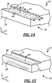
- FIGS. 13-15 show exemplary sheet metal pieces 12 with surfaces that include process markings or witness lines characteristic of the particular process used to form the weld notches 30.
- FIG. 13 is an example of one possible appearance of the weld notch surfaces 32, 34 and/or edge 28 when the weld notch 30 is formed by a laser ablasion process.
- the illustrated weld notch surfaces 32, 34 each include visible lines or markings 42.
- the markings 42 are generally parallel with the y-direction and evenly spaced from one another along the x-direction. Each individual marking indicates the location of a laser light beam edge during processing, where the laser light beam shape is square or rectangular and the laser light beam is provided as a pulsed beam rather than a continuous beam.
- the laser light beam may have dimensions in the x- and y-directions of L and W, respectively, and be directed at the edge region at the ablasion site 104 to remove material with a certain number of laser pulses.
- the light source may then be indexed by 1 ⁇ 2 L to remove more material, so that markings 42 are apparent every 1 ⁇ 2 L along the x-direction as shown.
- FIG. 13 includes similar ablasion markings along edge 28.
- the laser light beam may be shaped otherwise (e.g., round, oval, etc.) and successive ablasion sites may have more or less overlap.
- FIG. 14 shows circular markings 44, each with a length L equal to the diameter of a round laser light beam.
- successive markings 44 overlap by 1 ⁇ 2 of the beam diameter, and the first notch surface 32 has a scalloped shape.
- FIG. 15 is an example of one possible appearance of weld notch surfaces 32, 34 and/or edge 28 when the weld notch 30 is formed by a mechanical ablasion process.
- the illustrated weld notch surfaces 32, 34 each include visible lines or markings 46.
- the markings 46 are generally parallel with the x-direction in this embodiment and are randomly spaced from one another in the y-direction. These markings may be produced by irregularities in a scraping tool or by individual wires of a wire brush abrading the surfaces. Oriented as shown, markings 46 may result from a scraping tool scraping in the x-direction or a wire brush rotating about an axis in the y-direction. Markings 46, however, may be in other orientations as well, such as in the y-direction, diagonally in the x-y plane, or randomly.
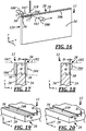
- first and second laser beams 102, 102' are directed at the edge region 20 from first and second laser sources 100, 100' located on opposite sides 24, 26 of the sheet metal piece in order to form the weld notches 30, 30'.
- This type of multi-laser arrangement allows the present method to simultaneously remove material from one or more material layers on opposite sides of the edge region 20, which can shorten the process time compared to the use of a single laser source.
- a multi-laser arrangement may offer improved selection and/or control of operating parameters for each side of the sheet metal piece 12, as two different types of laser sources or the same type of laser source programmed with different operating parameters can be custom tailored to each side. This may be useful, for example, where the material layers on one side of the sheet metal piece 12 have a different composition or thickness than those on the other side of the sheet metal.
- the laser sources 100, 100' may be offset or angled away from each another to avoid one laser source inadvertently striking or damaging the other laser source.
- the laser sources 100, 100' are located on the same or opposite sides of the sheet metal piece 12, but are spaced from one another so that they direct their respective laser beams towards different edge regions of the same sheet metal piece 12. For instance, one laser beam can be directed at the top edge region 20, while the other laser beam is directed to the side edge region 120.
- FIG. 17 is a cross-sectional view of a portion of the multi-laser arrangement of FIG. 16 , where the two laser beams 102, 102' are directed at the edge region 20 from opposite sides of the sheet metal piece 12 to form weld notches 30, 30' with a depth D and width W.
- weld notches 30, 30' with a depth D and width W.
- their respective sizes, shapes, etc. can be independent.
- laser beam 102 it is possible for laser beam 102 to produce a weld notch 30 that is different in terms of size, shape, depth, pattern, etc. than the weld notch 30' that is formed by laser beam 102'.
- the opposing ablation sites on opposite sides of sheet metal piece 12 may be mirror images of one another or they can vary depending on the particular needs of the application.
- laser beam 102 generates a laser spot or footprint 104 that has the same width W as the desired weld notch 30.
- the method is able to create weld notch 30 with a single pass of laser beam 102 along the length of edge region 20.
- FIG. 18 where laser beam 102 generates a laser spot 104 that has a smaller or narrower width than the desired weld notch width W.
- the laser beam 102 must make multiple passes in order to accommodate the wider width W of the weld notch, and may do so according to several different techniques.
- the laser beam 102 makes multiple passes along the full length of the edge region 20 (multiple passes in the x-axis direction), where each pass is indexed to a new y-axis position in order to accommodate the narrow laser spot 104.
- Such a technique may result in a weld notch with an ablation pattern 108, as illustrated in FIG. 19 .
- This technique may also be useful where it is desired to form a weld notch with a non-constant or non-uniform depth, as described in some of the examples above.
- the laser beam 102 may remove more material from the edge region 20 (i.e., create a greater depth D) during a first pass that tracks along the edge 28 of the sheet metal piece than during a second pass that is located more inboard and further away from the edge 28.
- the operating parameters of the laser source 102 could be controlled or manipulated in order to accomplish this.
- a different technique involves the laser beam 102 moving along the width of the edge region 20 (in the y-axis direction) before advancing to the next position along the length of the edge region (the x-axis direction).
- This type of back-and-forth technique can create a weld notch with an ablation pattern 110 like the own shown in FIG. 20 and results in only a single pass along the length of the edge region 20 (x-axis direction).
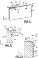
- FIGS. 21-23 there is shown an exemplary laser ablation process where laser beam 102 is directed at the edge region 20 according to a non-zero angle of incidence ⁇ .
- the angle of incidence ⁇ refers to the angle that is formed between a central axis A of the laser beam and a line B that is normal to the major surfaces of the sheet metal piece.
- the angle of incidence ⁇ can be positive or negative. In the embodiments of FIGS. 12 and 16 , the angle of incidence ⁇ is zero, and in the exemplary embodiment shown in FIGS. 21 and 22 , the angle of incidence ⁇ is between approximately 15° and 75° (e.g., about 25°). Other angles are certainly possible, depending on the particular application.
- a non-zero angle of incidence ⁇ can be used to form a weld notch 30 that is offset with respect to the different material layers of the sheet metal piece 12, such as that shown in FIG. 22 where the weld notch is crooked or tilted.
- Other examples of off-axis weld notches that can be formed using a laser beam at a non-zero angle of incidence are shown in FIGS. 7 and 8 .
- a non-zero angle of incidence ⁇ can also be used to simultaneously remove material from more than one surface of the sheet metal piece 12 with a single laser, such as from the edge surface 28 and from the side or major surface 24 at the same time. In other words, the laser beam 102 is directed at the edge region 20 according to an angle of incidence ⁇ such that it simultaneously impinges more than one surface of the sheet metal piece 12.
- Multi-surface laser impingement may be particularly useful when used with coated sheet metal pieces that have been cut or sheared after the coating process, such as when coated sheet metal rolls are cut into individual blanks or slit-to-width.
- the intermediate and/or coating material layers 16, 18 may become smeared or pulled onto edge 28 when the sheet metal is cut into individual blanks such that material from layers 16, 18 at least partly wraps around the corner or edge 112. This can be particularly true if the cutting or shearing equipment is dull or otherwise worn.
- the outlined arrow indicates the direction of shear.
- Removing the smeared material layers from both the edge surface 28 and the side surface 24 may further improve a subsequent weld joint at edge region 20, as both surfaces could potentially contaminate a nearby weld.
- a single laser aligned according to a non-zero angle of incidence ⁇ , as described above, or multiple lasers directed to the same edge region, as described below, could be used to remove material from intermediate and/or coating material layers 16, 18 that has become smeared or otherwise pulled down the edge surface 28.
- the method uses the lengthwise edge or corner 112 of the sheet metal piece 12 as a guide feature by aligning the laser beam 102 such that its center axis A strikes the sheet metal piece at or within a certain distance from the lengthwise edge 112 (e.g., within one-half of the laser spot width).
- Other alignment and guide techniques may be used as well.
- FIGS. 24 and 25 illustrate another exemplary laser ablation process.
- the first and second laser beams 102, 102' are directed at the edge region 20 according to different angles of incidence.
- Laser beam 102 is shown here impinging the edge region 20 at an angle of incidence that is approximately zero (normal to the side surface), while laser beam 102' impinges the edge region according to a non-zero angle of incidence ⁇ between approximately 15°-75° (e.g., about 45°). It is possible for the laser beams 102, 102' to be aimed or directed to the same laser spot or ablation site, or they could be directed at separate ablation sites 104, 104' that are spaced from one another along the x-axis, as shown.
- One potential reason for spacing the laser beams is to allow material that is splattered or expulsed by the first laser beam 102 to have time to at least partly solidify or react before being impinged and vaporized by the second laser beam 102'.
- the first laser beam 102 moves along the edge region 20 (x-axis direction) and removes material primarily from the side surface 24 of the sheet metal piece, while the second laser beam 102' follows behind and removes material from the edge surface 28.
- the resulting formation i.e., the notched out areas formed by both lasers 102, 102' -- constitutes the weld notch 30 and improves the weldability of the sheet metal piece 12 by removing material from one or more material layers at the future site of a potential weld joint.
- the enlarged cross-sectional view of FIG. 25 shows the edge region 20 after the first laser beam 102 has removed material from side surface 24, but before the second laser beam 102' has removed material from the edge surface 28.
- molten material struck by the first laser beam 102 can flow or splatter away from the weld notch 30 due to the rapid thermal expansion at the ablasion site.
- This molten material can be deposited nearby and form a resolidified or partially resolidified protrusion 114. If the protrusion 114 includes material from the material layers 16, 18, then any subsequently formed weld joint along edge region 20 could become contaminated or compromised.
- the second laser beam 102' may be directed with any suitable angle of incidence ⁇ , zero or non-zero, at the protrusion 114 in order to remove it from the edge region 20.
- the second laser beam 102' is replaced with a mechanical ablasion tool such as a scraper or wire brush for removal of the protrusion or other material along the edge surface 28.
- the mechanical ablation tool may follow behind the first laser beam 102 in the same setup as shown, or it could be used in an entirely separate operation.
- a non-limiting example of a suitable mechanical ablation tool is the scraper tool disclosed in U.S. Patent No. 7,971,303 to Prasad et al .
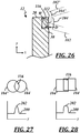
- FIGS. 26-28 there is shown another example of a multi-laser or dual-beam ablation process, where first and second laser beams 102, 102' overlap at a composite laser spot 116 where the combined energy of the lasers is greatest.
- the composite laser spot 116 is directed to the edge region 20 of the sheet metal piece 12 so that the composite laser spot at least partially covers the lengthwise edge or corner 112 and so that the most material removal occurs in this general area.
- Overlapping laser spots 104, 104' may be used to tailor or manipulate the laser energy distribution at the ablation site, as shown in FIGS. 27 and 28 .
- the round laser spots 104, 104' shown at the top of FIG. 27 overlap to form the composite laser spot 116, and an exemplary corresponding energy distribution 200 across the overlapping laser spots 104, 104" is shown in the chart at the bottom of FIG. 27 .
- the energy distribution 200 includes a peak or maxima 202 in the region of the composite laser spot 116 where both laser beams are present.
- the actual shape of the energy distribution may vary from that shown here depending on several factors, including the individual energy distributions of each laser spot, the distance of the focal plane from each laser spot, and other factors.
- Laser beams 102, 102' may emanate from laser sources that are co-located with each another and may extend toward the ablation site in a generally parallel manner (i.e., the two laser beams may have angles of incidence ⁇ that are within 10° of each another). This is somewhat different than the embodiment illustrated in FIG. 24 , where the laser beams originate from laser sources that are spaced in the x-axis direction (not co-located) and that extend towards the ablation site in a generally non-parallel manner. As mentioned previously, it is possible for the method to utilize the lengthwise edge 112 of the sheet metal piece as a guide feature when the laser beams are moving along the length of the edge region 20 (in the x-axis direction).
- This type of multi-laser or dual-beam process may be useful where it is desirable to form a weld notch 30 with a non-constant or non-uniform depth D across its width W, such as the weld notch illustrated in FIGS. 9-11 and 26 .
- this process may remove material from the coating material layer 18, the intermediate material layer 16, and the base material layer 14 at the composite laser spot 116, while only removing material from the coating material layer 18 and/or the intermediate material layer 16 at the non-overlapping portions of the laser spots 104, 104'.
- Overlapping laser spots may be used in conjunction with other previously described embodiments as well.
- the second laser beam 102' may be directed at the sheet metal piece 12 according to a non-zero angle of incidence.
- laser spot 116 depicts a composite laser spot 116 where the individual laser spots 104, 104' are rectangular in shape, as opposed to the previous example where they are circular. Laser spots or footprints having different sizes, shapes, configurations, etc. may be used in lieu of or in addition to those described herein.
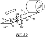
- FIG. 29 illustrates another embodiment of a laser ablation process, where the sheet metal piece 12 is provided from a roll or coil and is fed in a machine direction (indicated by the unnumbered outline arrow) past a plurality of laser sources 100, 100'.
- Each of the laser sources 100, 100' emits a laser beam toward a different location on the edge region 20, and may do so from a different side and/or at a different angle of incidence ⁇ than the other lasers.
- the first two laser beams encountered by the sheet metal piece as it moves in the machine direction may remove material primarily from the two side surfaces 24, 26 of the sheet metal piece, while the next two angled laser beams may remove resolidified protrusions (e.g., portion 114 of FIG.
- the illustrated process may be useful for feeding the sheet metal 12, complete with weld notches 30, 30', directly to downstream processes where it may be cut, sheared, and/or joined with other sheet metal pieces along edge region 20.
- the present method may employ a closed-loop feedback feature that automatically adjusts certain operating parameters in order to account for variations or changes in monitored process conditions, or it may utilize an iterative process in which certain operating parameters are incrementally or otherwise changed, to cite two possibilities.
- a laser ablation process may be configured to monitor a characteristic of the sheet metal piece 12, such as the absorptivity or reflectivity of the material at the ablation site or laser spot 104.
- the method may adjust an operating parameter of the laser, such as the pulse frequency and/or pulse width.
- an operating parameter of the laser such as the pulse frequency and/or pulse width.
- This dynamic approach can be useful where the various material layers of the sheet metal piece 12 each have different optimum operating parameters that can be tailored by the present method. For example, a certain pulse frequency and/or pulse width may be more effective for removing the coating material layer 18 than it is for removing the intermediate material layer 16 or the base material layer 14.
- the present method may be able to detect when laser beam 102 reaches a new material layer and to implement optimal operating parameters for that layer in response thereto.
- FIGS. 12 , 16 , 21 and 24 Another potential technique that may be used with any of the previously described embodiments involves arranging the sheet metal piece in a generally vertical orientation during the laser ablation process, as illustrated in FIGS. 12 , 16 , 21 and 24 . Because of the vertical orientation, gravity can cause any molten material near the ablation site to flow in a desired direction. For example, if it is desirable to have molten material flow away from the edge 28 of the sheet metal piece, which is where a subsequently formed weld joint is likely to be located, then a vertical orientation similar to that the referenced figures can be used. This reduces the probability of molten coating material flowing toward the edge 28 and solidifying there, where it could be problematic in subsequent weld processes along that edge. The sheet metal piece need not be perfectly vertical, however.
- the sheet metal piece is oriented so that the edge region 20 from which material is being removed is located higher than the remainder of the sheet metal piece.
- the sheet metal piece 12 may be oriented so that the side from which material is being removed is facing down during the laser ablasion process so that any excess molten material drips or flows away from the edge region 20.
- FIG. 16 Another technique useful to help prevent molten material from solidifying along the edge 28 of the sheet metal piece to be welded is to provide a high velocity jet 118 of air (see FIG. 16 ) or other fluid (e.g. nitrogen or an inert gas) at the location of the laser spot or ablation site 104 to blow molten material away from the edge.
- the jet 118 of air is located beyond the sheet metal piece surfaces so that the air flows in a direction towards the edge 28 (in the downward y-direction) to blow molten material towards the still-coated portion of the sheet metal piece.
- a jet 118 of air may alternatively or additionally be directed along the weld notch in the direction of laser movement (in the horizontal x-direction of FIG. 16 ).
- a plurality of jets 118 are directed along the edge region to help prevent molten material from solidifying along the edge of the sheet metal piece.
- the individual jets can be directed all in the same direction or in different directions with respect to one another. Some of the preceding techniques may be used with sheet metal pieces arranged in horizontal orientations as well.
- the process also includes laser cutting of the sheet metal piece.
- Laser cutting employs a relatively high-powered laser, usually in a continuous mode rather than a pulsed energy mode, to separate a piece of sheet metal into two or more individual pieces.
- the laser beam delivers sufficient energy to the sheet metal piece at the desired location of separation to melt and/or vaporize the base material layer.
- a high-velocity jet of air or other fluid can follow the laser beam to blow the molten material away from the sheet metal piece and effectively separate it into two individual sheet metal pieces with newly formed edges and edge regions.
- Laser cutting may thus be considered one form of a laser ablation process useful for preventing unwanted constituents from inclusion in nearby and subsequently formed weld joints, and is a process that simultaneously cuts the sheet metal into individual blanks or other pieces while removing one or more layers of coating material.
Description
- The present disclosure generally relates to sheet metal pieces and, more particularly, to sheet metal pieces that are coated with one or more thin material layers and are used in welding processes.
- In an effort to improve resistance to corrosion, scaling and/or other processes, sheet metal made of high-strength or hardenable steel alloys are now being made with one or more thin coating material layers, such as aluminum- and zinc-based layers. Although these coating material layers can impart desirable qualities to the sheet metal, their presence can contaminate welds, thereby reducing weld strength, integrity, etc. This is particularly true if the coated sheet metal piece is being butt welded or lap welded to another sheet metal piece.
- Document
US 2003/0201037 A1 shows a manufacturing process for assembly parts for the manufacture of elements of chemical devices, comprising the fixation of an anticorrosion metallic coating on an unprocessed assembly part, by means of an operation comprising a brazing operation under a controlled atmosphere and, possibly, the shaping of the coated part, by plastic deformation. - Document
JP H03 258484 A - Document
US 2009/0220815 A1 , regarded as the closest prior art, shows a plate consisting of a steel substrate and a precoat consisting of a layer of intermetallic alloy in contact with said substrate, topped by a layer of metal alloy, characterized in that, on at least one precoated face of said plate, an area situated at the periphery of said plate has said metal alloy layer removed. - There is provided a sheet metal piece according to claim 1 and a method for forming a weld notch according to claim 8.
- In accordance with one or more examples, a sheet metal piece for use in a welding process includes a base material layer, a coating material layer, and an intermediate material layer. The intermediate material layer is located between the base material layer and the coating material layer and includes an intermetallic compound having at least one constituent from each of the base material layer and the coating material layer. The sheet metal piece includes an edge region located along an edge of the sheet metal piece that is to be welded. The edge region includes a weld notch defined at least partially by a weld notch surface that includes material from both the coating material layer and the intermediate material layer.
- In accordance with one or more other examples, a method of forming a weld notch in a sheet metal piece comprises the steps of: (a) providing a sheet metal piece having a plurality of material layers at an edge region; (b) directing a laser beam towards the edge region of the sheet metal piece; and (c) removing material from at least one of the plurality of material layers at the edge region of the sheet metal piece with the laser beam so that a weld notch is formed where the removed material is no longer present.
- Preferred exemplary embodiments will hereinafter be described in conjunction with the appended drawings, wherein like designations denote like elements, and wherein:
-
FIGS. 1A-C are cross-sectional views of a conventional weld joint joining sheet metal pieces that did not have weld notches formed therein before welding; -
FIG. 2 is a perspective view of an edge region of an exemplary sheet metal piece, including weld notches on opposite sides of the sheet metal piece; -
FIG. 3 is a cross-sectional view of a portion of the sheet metal piece ofFIG. 2 , showing coating layers, intermediate material layers, and weld notches on opposite sides of the sheet metal piece; -
FIG. 4 is an enlarged view of a portion ofFIG. 3 , showing irregular surfaces between material layers; -
FIG. 5 is a cross-sectional view of an exemplary sheet metal piece including a weld notch, where the coating material layer and the intermediate material layer are removed; -
FIG. 6 is a cross-sectional view of another exemplary sheet metal piece including a weld notch, where the coating material layer, the intermediate material layer, and a portion of the base material layer are removed; -
FIG. 7 is a cross-sectional view of another exemplary sheet metal piece including an off-axis weld notch; -
FIG. 8 is a cross-sectional view of another exemplary sheet metal piece including a different off-axis weld notch; -
FIG. 9 is a cross-sectional view of another exemplary sheet metal piece including a weld notch with a non-uniform depth; -
FIG. 10 is a cross-sectional view of an example sheet metal piece useful for understanding the invention including a different weld notch with a non-uniform depth; -
FIG. 11 is a cross-sectional view of another exemplary sheet metal piece including a weld notch with a non-uniform depth and multiple intersecting surfaces; -
FIG. 12 is a perspective view of an exemplary laser ablation process for forming a weld notch; -
FIG. 13 is an enlarged perspective view of an exemplary sheet metal piece with a weld notch formed by laser ablasion; -
FIG. 14 is an enlarged perspective view of another exemplary sheet metal piece with a weld notch formed by laser ablasion by a different laser; -
FIG. 15 is an enlarged perspective view of another exemplary sheet metal piece having a weld notch formed by a mechanical ablasion process; -
FIG. 16 is a perspective view of an exemplary dual-laser beam ablation process; -
FIG. 17 is a cross-sectional view of the laser ablation process ofFIG. 16 ; -
FIG. 18 is a cross-sectional view of another exemplary laser ablation process, where the laser spot is narrower than the width of the desired weld notch; -
FIG. 19 is an enlarged perspective view of a weld notch that may be formed by the laser ablation process ofFIG. 18 ; -
FIG. 20 is an enlarged perspective view of a weld notch that may also be formed by the laser ablation process ofFIG. 18 ; -
FIG. 21 is a perspective view of another exemplary laser ablation process, where the process forms a weld notch using a laser with a non-zero angle of incidence; -
FIG. 22 is a cross-sectional view of the laser ablation process fromFIG. 21 , where the process forms an offset weld notch on a single side of the sheet metal piece; -
FIG. 23 is an enlarged cross-sectional view of an edge region of the sheet metal piece fromFIG. 21 prior to formation of the offset weld notch; -
FIG. 24 is a perspective view of another exemplary laser ablation process being performed on a sheet metal piece, where the process uses multiple lasers to form a weld notch; -
FIG. 25 is a cross-sectional view of the laser ablation process fromFIG. 24 , where the process forms a weld notch with multiple non-overlapping lasers; -
FIG. 26 is another cross-sectional view of the laser ablation process fromFIG. 24 , where the process forms a weld notch with multiple overlapping lasers; -
FIG. 27 illustrates overlapping laser spots or footprints that may be used with the laser ablation process ofFIG. 26 and a corresponding energy distribution; -
FIG. 28 illustrates overlapping laser spots or footprints that may be used with the laser ablation process ofFIG. 26 and another corresponding energy distribution; and -
FIG. 29 is a perspective view of another exemplary laser ablation process being performed on a sheet metal piece coming off of a metal coil, where the process uses multiple lasers to form weld notches on opposite sides of the sheet metal piece. - The sheet metal pieces disclosed herein can be made with weld notches located along one or more edges, where the weld notches are characterized by the absence of certain material constituents so that they do not unacceptably contaminate nearby welds. For instance, a sheet metal piece can be produced so that material from one or more coating material layers is reduced or removed at a weld notch located along the sheet metal edge. This, in turn, can prevent contamination by the coating material layers of a nearby weld joint formed along the sheet metal edge and thereby preserve the strength and/or durability of the weld joint in subsequent processes or during its service life.
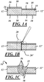
- Turning first to
FIGS. 1A-C , there are shown some of the steps involved with manufacturing a conventional tailor-welded blank 10 that includes thick and thinsheet metal pieces 12, 12' laser welded together in an edge-to-edge fashion. According to this example, each of thesheet metal pieces 12, 12' has abase material layer 14 and multiplethin material layers edge regions 20, 20' so that a certain amount of thethin material layers weld joint 22. Unless first removed, these unwanted constituents could have a negative impact on the overall strength and quality of the weld joint. - Referring to
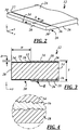
FIG. 2 , there is shown an exemplarysheet metal piece 12 that may be welded to an adjacent piece alongedge region 20. Thesheet metal piece 12 includes opposite first andsecond sides edge region 20 is located along anedge 28 of the sheet metal piece that is to be welded. Theparticular edge region 20 shown inFIG. 2 includes twoweld notches 30, 30', where the two weld notches extend along the edge region onopposite sides sheet metal piece 12. Eachweld notch 30, 30' is defined by afirst notch surface 32 and asecond notch surface 34 that intersect or join each other. Though shown with generally perpendicular first andsecond notch surfaces straight edge region 20, the weld notches may be configured in numerous ways. For example, a weld notch can include one or more off-axis notch surface(s), have different dimensions than another weld notch of the same sheet metal piece, be formed as part of a different edge region than another weld notch, and/or be formed as part of an edge region located along a contoured edge of the sheet metal piece, to cite several possibilities. Some of these different embodiments are illustrated in the drawings. -
FIG. 3 is a cross-section of theedge region 20 of thesheet metal piece 12 ofFIG. 2 . The illustratedsheet metal piece 12 includes multiple material layers, including thebase material layer 14, intermediate material layers 16, and coating material layers 18. In this embodiment, thebase material layer 14 is the central or core material layer (e.g., a steel core) and is sandwiched between the intermediate material layers 16 and the coating material layers 18. Thebase material layer 14 makes up the majority of the thickness T of thesheet metal piece 12 and thus may contribute significantly to the mechanical properties of the sheet metal piece. The coating material layers 18 are located over opposite surfaces of thebase material layer 14 and are the outermost layers of thesheet metal piece 12. Eachcoating material layer 18 is relatively thin with respect to thebase material layer 14 and may be selected to enhance one or more characteristics of the sheet metal piece (e.g., corrosion resistance, hardness, weight, formability, appearance, etc.). Thecoating material layer 18 may also be selected for use or compatibility with subsequent processes, such as heat treatment or interdiffusion processes, for example. - Each
intermediate layer 16 is located between thebase material layer 14 and one of the coating material layers 18, and is in contact with each in this embodiment. In one embodiment, theintermediate material layer 16 includes at least one constituent in common with each of the immediatelyadjacent layers intermediate material layer 16 may be a reaction product of the base and coating material layers 14, 18. For example, a dip coating process, in which the base material layer is immersed or passes through a molten bath of coating layer material, can result in a chemical reaction at the interface of the base material layer and the molten bath, and the reaction product is theintermediate layer 16. In one specific example of such a dip coating process, thebase material layer 14 is made of a high-strength or hardenable steel alloy and thecoating material layer 18 is an aluminum alloy. The molten bath of aluminum alloy reacts with the base material layer at its surface to form theintermediate material layer 16, which includes iron-aluminum (FexAly) intermetallic compounds such as Fe2Al5. The intermediate layer can have a higher content of the base material layer constituent (e.g., iron) closer thebase material layer 14 and a higher content of the coating material layer constituent (e.g., aluminum) closer to thecoating material layer 18. - Though shown in
FIG. 3 as a perfectly planar layer with a constant thickness, theintermediate material layer 16 may be irregular along its opposite surfaces as depicted in the enlarged view ofFIG. 4 . It should also be understood that theintermediate material layer 16 is not necessarily uniform in composition throughout, nor is it necessarily a reaction product of the base material layer and the coating material layer. Theintermediate material layer 16 may itself include more than one layer of material, may be a non-homogenous mixture of different materials, or may have a composition gradient through its thickness, to name a few examples. In another example, the intermediate layer includes a continuous or discontinuous oxide layer, such as an oxide of thebase material layer 14 that can form with exposure of the base material layer to the environment (e.g., aluminum oxides, iron oxides, etc.). Thesheet metal piece 12 may include other, additional material layers as well. - One specific example of a multi-layered sheet metal piece useful for forming body and structural components in the automotive and other industries, such as that shown in
FIG. 3 , is a coated steel product in which thebase material layer 14 is made from steel in any of its various possible compositions. In one particular embodiment, thebase material layer 14 is a high-strength or hardenable steel alloy such as a boron steel alloy, dual phase steel, press hardened steel (PHS) or a high-strength low-alloy (HLSA) steel. Such materials, while strong for their weight, often require heat treating processes to attain the high-strength properties and/or can only be formed at high temperatures. Thecoating material layer 18 may be selected to help prevent oxidation during heat treatment, to be lighter in weight than thebase material layer 14, and/or to interdiffuse with the other layers of thesheet metal piece 12 during subsequent heat treatment. In one embodiment, thecoating material layer 18 is an aluminum (Al) alloy, such as an Al-silicone (Al-Si) alloy. Other possible compositions forcoating material layer 18 include pure aluminum or zinc and its alloys or compounds (e.g., where the underlying material is galvanized). Where thebase material layer 14 is steel and thecoating material layer 18 comprises aluminum, theintermediate material layer 16 may include iron and aluminum in the form of intermetallic compounds such as FeAl, FeAl2, Fe3Al, Fe2Al5 or various combinations thereof. Theintermediate material layer 16 may also include an alloy of constituents from adjacent layers. - Exemplary material layer thicknesses range from about 0.5 mm to about 2.0 mm for the
base material layer 14, from about 1 µm to about 15 µm for theintermediate layer 16, and from about 5 µm to about 100 µm for thecoating material layer 18. Preferred material layer thicknesses range from about 0.5 mm to about 1.0 mm for thebase material layer 14, from about 5 µm to about 10 µm for theintermediate layer 16, and from about 15 µm to about 50 µm for thecoating material layer 18. In one embodiment, the combined thickness of the intermediate and coating material layers 16, 18 is in a range from about 15 µm to about 25 µm, and the intermediate material layer is about 20-30% of the combined thickness. For instance, the combined thickness oflayers base material layer 14 can be a material other than steel, such as alloys of aluminum, magnesium, titanium, or other suitable materials. The weld notches described herein may be used with more or less layers of material than shown in the figures. Skilled artisans will also appreciate that the figures are not necessarily to scale and that the relative thicknesses of layers 14-18 may differ from those illustrated in the drawings. - Referring again to
FIG. 3 , theweld notch 30 on thefirst side 24 of the sheet metal piece will be described. This description applies to the weld notch 30' on the oppositesecond side 26 as well, in this example. Theweld notch 30 is a portion of theedge region 20 of thesheet metal piece 12 where some material has been removed or omitted from the otherwise uniform layered structure. Theweld notch 30 promotes a high quality weld joint alongedge 28 when the sheet metal piece is welded to another piece, and may do so via a configuration that reduces or eliminates the amount of thecoating material layer 18 and/or theintermediate material layer 16 that becomes part of a subsequent weld joint. The weld notch is particularly useful where thecoating material layer 18 includes one or more constituents that form discontinuities in or would otherwise weaken the resulting weld joint if included therein. Theweld notch 30 has a characteristic notch width W and notch depth D, each being relatively constant along the length ofedge 28 in this particular embodiment. The notch width W is the distance fromedge 28 to thefirst notch surface 32, and the notch depth D is the distance from the outer surface of thecoating material layer 18 to thesecond notch surface 34. Where theweld notch 30 is square with the sheet metal piece, as shown in this particular example, the notch width W is equal to the width of thesecond notch surface 34, and the notch depth D is equal to the width of thefirst notch surface 32. - The dimensions of the
weld notch 30 may be related to the thickness T of the sheet metal piece, to the intended size of the weld joint to be formed atedge 28, and/or to one or more material layer thicknesses. In one embodiment, notch width W is in a range from about 0.5 to about 1.5 times the thickness T. In another embodiment, the notch width W is in a range from about 0.5 mm to about 4 mm. The notch width W may also be at least one half of the width of the intended weld joint. The notch depth D for the example shown inFIG. 3 is greater than the thickness of thecoating material layer 18 and less than the combined thickness of the intermediate and coating material layers 16, 18. But this differs in some of the other exemplary embodiments. - The
weld notch 30 can also be described with relation to certain characteristics of the notch surfaces 32, 34. For example, in the example ofFIG. 3 , thefirst notch surface 32 includes material from both of theintermediate material layer 16 and thecoating material layer 18. Thesecond notch surface 34 includes material from theintermediate material layer 16 only, and the first and second notch surfaces intersect along an edge that is positioned or located in the intermediate material layer. Thus, in this particular example, theweld notch 30 is formed in thesheet metal piece 12 by removing the entirecoating material layer 18 and a portion of theintermediate material layer 16 alongedge region 20. Each of the notch surfaces 32, 34 may also include striations, witness lines, or other indicators of the type of process used to remove material at the weld notch location. Ablasion processes such as laser ablasion or mechanical ablasion can form notch surfaces with different surfaces characteristics and are subsequently described in further detail. -
FIG. 5 shows another example of aweld notch 30, where the first and second notch surfaces 32, 34 intersect along an edge that is located at the interface between thebase material layer 14 and theintermediate material layer 16. Thefirst notch surface 32 includes material from both of theintermediate material layer 16 and thecoating material layer 18, and thesecond notch surface 34 includes material from thebase material layer 14 only. In this example, theweld notch 30 is formed in thesheet metal piece 12 by removing thecoating material layer 18 and theintermediate material layer 16 atedge region 20. -
FIG. 6 illustrates aweld notch 30 with first and second notch surfaces 32, 34 that intersect each other along an edge that is located in thebase material layer 14. Thefirst notch surface 32 includes material from thebase material layer 14, theintermediate material layer 16, and thecoating material layer 18, while thesecond notch surface 34 includes material from thebase material layer 14 only. In this example, theweld notch 30 is formed in thesheet metal piece 12 by removing thecoating material layer 18, theintermediate material layer 16, and a portion of the thickness of thebase material layer 14 atedge region 20. -
FIG. 7 shows another embodiment ofsheet metal piece 12, where theweld notch 30 is off-axis. In other words, at least one notch surface (in this case both notch surfaces 32, 34) is neither perpendicular nor parallel with the outermost surface of thecoating material layer 18. The notch surfaces 32, 34 may be perpendicular with each other as shown and form respective angles α and β with the outermost surface of thecoating material layer 18. Angle β is less than 90° in this example (90° - α), but could be greater than or equal to 90°. In the example ofFIG. 7 , thefirst notch surface 32 includes material from theintermediate material layer 16 and thecoating material layer 18, while thesecond notch surface 34 includes material from thebase material layer 14 and theintermediate material layer 16. The notch surfaces 32, 34 intersect each other along anedge 36 in theintermediate material layer 16. Thisweld notch 30 may be formed in thesheet metal piece 12 by removing thecoating material layer 18, a portion of the thickness of theintermediate material layer 16, and a portion of the thickness of thebase material layer 14 atedge region 20. -
FIG. 8 shows a sheet metal piece according to another embodiment, where theweld notch 30 is in the form of a chamfer or angled surface and is defined bynotch surface 32.Notch surface 32 is planar (i.e., generally planar, not necessarily perfectly planar) and includes material from all of the base, intermediate, and coating material layers 14-18, and intersectsedge 28 of thesheet metal piece 12 along an edge located in thebase material layer 14. In another embodiment, the chamfer-like weld notch 30 includes material from theintermediate material layer 16 and thecoating material layer 18 only, but not from thebase material layer 14, thus intersectingedge 28 in theintermediate layer 16 or at the interface between thebase material layer 14 and theintermediate layer 16. -
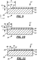
FIG. 9 shows a sheet metal piece according to another embodiment, where theweld notch 30 is defined by a curved orcontoured notch surface 32. Thenotch surface 32 shown here includes material from all of the base, intermediate, and coating material layers 14-18, and intersectsedge 28 of thesheet metal piece 12 along an edge located in thebase material layer 14. The depth D of theweld notch 30 is variable and is illustrated as being measured at its maximum value in this particular example, which is at theedge 28 of thesheet metal piece 12. In another embodiment, the contouredweld notch 30 includes material from theintermediate material layer 16 and thecoating material layer 18 only, but not from thebase material layer 14, thus intersectingedge 28 in theintermediate layer 16 or at the interface between thebase material layer 14 and theintermediate layer 16. -
FIG. 10 shows a sheet metal piece according to an example useful for understanding the invention, where theweld notch 30 is defined by acontoured notch surface 32 that is different from that ofFIG. 9 . Thenotch surface 32 shown here includes material from all of the base, intermediate, and coating material layers 14-18, and intersectsedge 28 of thesheet metal piece 12 along an edge located in thebase material layer 14. The depth D of theweld notch 30 is variable and is illustrated as being measured at its maximum value in this particular example, which is in thebase material layer 14 and spaced away from theedge 28 of thesheet metal piece 12 in this particular example. -
FIG. 11 shows another embodiment ofsheet metal piece 12, where theweld notch 30 is defined by afirst notch surface 32, asecond notch surface 34, and athird notch surface 38. This embodiment has first and second notch surfaces 32, 34, as described above and shown inFIG. 3 , that intersect along an edge located in theintermediate material layer 16. Thethird notch surface 38 is a contoured notch surface that intersects thesecond notch surface 34 along anedge 40 located inintermediate material layer 16 at one end, and theedge 28 of thesheet metal piece 12 at the other end. Thethird notch surface 38 includes material from thebase material layer 14 and theintermediate material layer 16, in this example. The depth of theweld notch 30 along the second and/or third notch surfaces 34, 38 may vary from that shown inFIG. 11 , as may the width of the second and/or third notch surfaces. Skilled artisans will appreciate the wide variety of combinations of notch surface shapes, widths, and depths that are possible. -
FIGS. 7 to 9 and11 collectively show various embodiments of sheet metal pieces andFig. 10 an example useful for understanding the invention withweld notches 30 that each has a non-uniform depth. In other words, in these examples, the depth of eachweld notch 30 varies across the one or more weld notch surfaces depending on how far from theedge 28 of the sheet metal piece the depth is measured. In most of these embodiments, with the exception of that shown inFIG. 10 , the average depth of the weld notch is greatest towards the edge of the sheet metal. These types of weld notches can be formed by ablasion processes in which an ablasion tool makes multiple passes along different portions of theedge region 20, or where the ablasion tool is configured to remove different amounts of material from the sheet metal piece as a function of distance from theedge 28. - Referring now to
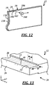
FIG. 12 , there is shown an exemplary process for forming a weld notch in a sheet metal piece. The particular process shown schematically in the figure is a laser ablasion process in which alaser light source 100 emits alaser light beam 102 directed at theedge region 20 of thesheet metal piece 12. Energy provided by thelaser light beam 102 is transferred to thepiece 12 in the form of thermal energy at anablasion site 104, melting and/or vaporizing material at a focal point to remove it from thesheet metal piece 12. The ablasion tool, whether a laser light beam or a mechanical tool such as a scraper or wire brush, follows apath 106 along theedge region 20 to form aweld notch 30 of the desired configuration. Some portions of thepath 106 can be rectilinear as shown in the figure, and other portions can be contoured or curvilinear. For example, theweld notch 130 shown inFIG. 12 is contoured to follow the shape ofedge 128. It is not necessary for theweld notch 30 to follow astraight path 106, as paths having other configurations can be followed instead. For sheet metal pieces that include base, intermediate, and coating material layers 14, 16, 18, such as that shown inFIG. 3 , theweld notch 30 may be formed by removing all or some of thecoating material layer 18, all or some of theintermediate material layer 16, and/or some of thebase material layer 14 along theedge region 20. - In this and other embodiments where laser ablation is employed, the
sheet metal piece 12 may be held stationary while thelaser source 100 moves thelaser beam 102 along thepath 106, as indicated by the arrow inFIG. 12 . In a different embodiment, thesheet metal piece 12 is moved or indexed while thelaser source 100 remains stationary. Other techniques, such as moving both the laser source and the sheet metal piece, may be employed as well. Any suitable laser or other comparable light emittingdevice 100 may be used to form the weld notches, and may do so using a variety of operating or equipment parameters. In one example, thelaser source 100 is a Q-switched laser, but other continuous wave and pulsed laser types may be used instead such as various nanosecond, femtosecond and picosecond pulsed lasers. The laser spot orfootprint 104 can be round, square, rectangular, elliptical, or any other suitable shape, some examples of which are subsequently described. Non-limiting examples of selectable or adjustable operating parameters for thelaser source 100 include: laser power, pulse frequency, pulse width, pulse energy, pulse power, duty cycle, spot area, the overlap between successive laser pulses, and the speed oflaser source 100 relative tosheet metal piece 12, to cite a few possibilities. Any combination of these operating parameters may be selected and controlled by the present method based on the particular needs of the application. Various examples of laser ablation processes are described in further detail below. -
FIGS. 13-15 show exemplarysheet metal pieces 12 with surfaces that include process markings or witness lines characteristic of the particular process used to form theweld notches 30.FIG. 13 is an example of one possible appearance of the weld notch surfaces 32, 34 and/or edge 28 when theweld notch 30 is formed by a laser ablasion process. The illustrated weld notch surfaces 32, 34 each include visible lines or markings 42. The markings 42 are generally parallel with the y-direction and evenly spaced from one another along the x-direction. Each individual marking indicates the location of a laser light beam edge during processing, where the laser light beam shape is square or rectangular and the laser light beam is provided as a pulsed beam rather than a continuous beam. For example, the laser light beam may have dimensions in the x- and y-directions of L and W, respectively, and be directed at the edge region at theablasion site 104 to remove material with a certain number of laser pulses. The light source may then be indexed by ½ L to remove more material, so that markings 42 are apparent every ½ L along the x-direction as shown. The example ofFIG. 13 includes similar ablasion markings alongedge 28. - The laser light beam may be shaped otherwise (e.g., round, oval, etc.) and successive ablasion sites may have more or less overlap. For example,
FIG. 14 shows circular markings 44, each with a length L equal to the diameter of a round laser light beam. In this example, successive markings 44 overlap by ½ of the beam diameter, and thefirst notch surface 32 has a scalloped shape. -
FIG. 15 is an example of one possible appearance of weld notch surfaces 32, 34 and/or edge 28 when theweld notch 30 is formed by a mechanical ablasion process. The illustrated weld notch surfaces 32, 34 each include visible lines or markings 46. The markings 46 are generally parallel with the x-direction in this embodiment and are randomly spaced from one another in the y-direction. These markings may be produced by irregularities in a scraping tool or by individual wires of a wire brush abrading the surfaces. Oriented as shown, markings 46 may result from a scraping tool scraping in the x-direction or a wire brush rotating about an axis in the y-direction. Markings 46, however, may be in other orientations as well, such as in the y-direction, diagonally in the x-y plane, or randomly. - Referring now to
FIG. 16 , there is shown another exemplary method for forming aweld notch 30 in asheet metal piece 12 using a laser ablation process. In this method, first andsecond laser beams 102, 102' are directed at theedge region 20 from first andsecond laser sources 100, 100' located onopposite sides weld notches 30, 30'. This type of multi-laser arrangement allows the present method to simultaneously remove material from one or more material layers on opposite sides of theedge region 20, which can shorten the process time compared to the use of a single laser source. In addition, a multi-laser arrangement may offer improved selection and/or control of operating parameters for each side of thesheet metal piece 12, as two different types of laser sources or the same type of laser source programmed with different operating parameters can be custom tailored to each side. This may be useful, for example, where the material layers on one side of thesheet metal piece 12 have a different composition or thickness than those on the other side of the sheet metal. Although shown directly facing each another inFIG. 16 , thelaser sources 100, 100' may be offset or angled away from each another to avoid one laser source inadvertently striking or damaging the other laser source. In another example, thelaser sources 100, 100' are located on the same or opposite sides of thesheet metal piece 12, but are spaced from one another so that they direct their respective laser beams towards different edge regions of the samesheet metal piece 12. For instance, one laser beam can be directed at thetop edge region 20, while the other laser beam is directed to the side edge region 120. -
FIG. 17 is a cross-sectional view of a portion of the multi-laser arrangement ofFIG. 16 , where the twolaser beams 102, 102' are directed at theedge region 20 from opposite sides of thesheet metal piece 12 to formweld notches 30, 30' with a depth D and width W. Although shown here with the same size laser beams, spots, and weld notches on opposite sides of thesheet metal piece 12 generally opposing one another through the thickness of the sheet metal piece, their respective sizes, shapes, etc. can be independent. For example, it is possible forlaser beam 102 to produce aweld notch 30 that is different in terms of size, shape, depth, pattern, etc. than the weld notch 30' that is formed by laser beam 102'. The opposing ablation sites on opposite sides ofsheet metal piece 12 may be mirror images of one another or they can vary depending on the particular needs of the application. In the particular example shown inFIG. 17 ,laser beam 102 generates a laser spot orfootprint 104 that has the same width W as the desiredweld notch 30. Thus, the method is able to createweld notch 30 with a single pass oflaser beam 102 along the length ofedge region 20. This is different than the example shown inFIG. 18 , wherelaser beam 102 generates alaser spot 104 that has a smaller or narrower width than the desired weld notch width W. In this case, thelaser beam 102 must make multiple passes in order to accommodate the wider width W of the weld notch, and may do so according to several different techniques. - According to one potential technique, the
laser beam 102 makes multiple passes along the full length of the edge region 20 (multiple passes in the x-axis direction), where each pass is indexed to a new y-axis position in order to accommodate thenarrow laser spot 104. Such a technique may result in a weld notch with anablation pattern 108, as illustrated inFIG. 19 . This technique may also be useful where it is desired to form a weld notch with a non-constant or non-uniform depth, as described in some of the examples above. For instance, thelaser beam 102 may remove more material from the edge region 20 (i.e., create a greater depth D) during a first pass that tracks along theedge 28 of the sheet metal piece than during a second pass that is located more inboard and further away from theedge 28. The operating parameters of thelaser source 102 could be controlled or manipulated in order to accomplish this. A different technique involves thelaser beam 102 moving along the width of the edge region 20 (in the y-axis direction) before advancing to the next position along the length of the edge region (the x-axis direction). This type of back-and-forth technique can create a weld notch with anablation pattern 110 like the own shown inFIG. 20 and results in only a single pass along the length of the edge region 20 (x-axis direction). - Turning now to
FIGS. 21-23 , there is shown an exemplary laser ablation process wherelaser beam 102 is directed at theedge region 20 according to a non-zero angle of incidence α. The angle of incidence α, as used herein, refers to the angle that is formed between a central axis A of the laser beam and a line B that is normal to the major surfaces of the sheet metal piece. The angle of incidence α can be positive or negative. In the embodiments ofFIGS. 12 and16 , the angle of incidence α is zero, and in the exemplary embodiment shown inFIGS. 21 and 22 , the angle of incidence α is between approximately 15° and 75° (e.g., about 25°). Other angles are certainly possible, depending on the particular application. A non-zero angle of incidence α can be used to form aweld notch 30 that is offset with respect to the different material layers of thesheet metal piece 12, such as that shown inFIG. 22 where the weld notch is crooked or tilted. Other examples of off-axis weld notches that can be formed using a laser beam at a non-zero angle of incidence are shown inFIGS. 7 and 8 . A non-zero angle of incidence α can also be used to simultaneously remove material from more than one surface of thesheet metal piece 12 with a single laser, such as from theedge surface 28 and from the side ormajor surface 24 at the same time. In other words, thelaser beam 102 is directed at theedge region 20 according to an angle of incidence α such that it simultaneously impinges more than one surface of thesheet metal piece 12. - Multi-surface laser impingement may be particularly useful when used with coated sheet metal pieces that have been cut or sheared after the coating process, such as when coated sheet metal rolls are cut into individual blanks or slit-to-width. With reference to the enlarged view of
FIG. 23 , the intermediate and/or coating material layers 16, 18 may become smeared or pulled ontoedge 28 when the sheet metal is cut into individual blanks such that material fromlayers edge 112. This can be particularly true if the cutting or shearing equipment is dull or otherwise worn. InFIG. 23 , the outlined arrow indicates the direction of shear. Removing the smeared material layers from both theedge surface 28 and theside surface 24 may further improve a subsequent weld joint atedge region 20, as both surfaces could potentially contaminate a nearby weld. A single laser aligned according to a non-zero angle of incidence α, as described above, or multiple lasers directed to the same edge region, as described below, could be used to remove material from intermediate and/or coating material layers 16, 18 that has become smeared or otherwise pulled down theedge surface 28. It is possible for the method to use the lengthwise edge orcorner 112 of thesheet metal piece 12 as a guide feature by aligning thelaser beam 102 such that its center axis A strikes the sheet metal piece at or within a certain distance from the lengthwise edge 112 (e.g., within one-half of the laser spot width). Other alignment and guide techniques may be used as well. -
FIGS. 24 and 25 illustrate another exemplary laser ablation process. In this embodiment, the first andsecond laser beams 102, 102' are directed at theedge region 20 according to different angles of incidence.Laser beam 102 is shown here impinging theedge region 20 at an angle of incidence that is approximately zero (normal to the side surface), while laser beam 102' impinges the edge region according to a non-zero angle of incidence α between approximately 15°-75° (e.g., about 45°). It is possible for thelaser beams 102, 102' to be aimed or directed to the same laser spot or ablation site, or they could be directed atseparate ablation sites 104, 104' that are spaced from one another along the x-axis, as shown. One potential reason for spacing the laser beams is to allow material that is splattered or expulsed by thefirst laser beam 102 to have time to at least partly solidify or react before being impinged and vaporized by the second laser beam 102'. In the embodiment shown inFIGS. 24 and 25 , thefirst laser beam 102 moves along the edge region 20 (x-axis direction) and removes material primarily from theside surface 24 of the sheet metal piece, while the second laser beam 102' follows behind and removes material from theedge surface 28. The resulting formation -- i.e., the notched out areas formed by bothlasers 102, 102' -- constitutes theweld notch 30 and improves the weldability of thesheet metal piece 12 by removing material from one or more material layers at the future site of a potential weld joint. - The enlarged cross-sectional view of
FIG. 25 shows theedge region 20 after thefirst laser beam 102 has removed material fromside surface 24, but before the second laser beam 102' has removed material from theedge surface 28. At this stage, molten material struck by thefirst laser beam 102 can flow or splatter away from theweld notch 30 due to the rapid thermal expansion at the ablasion site. This molten material can be deposited nearby and form a resolidified or partiallyresolidified protrusion 114. If theprotrusion 114 includes material from the material layers 16, 18, then any subsequently formed weld joint alongedge region 20 could become contaminated or compromised. The second laser beam 102' may be directed with any suitable angle of incidence α, zero or non-zero, at theprotrusion 114 in order to remove it from theedge region 20. In another embodiment, the second laser beam 102' is replaced with a mechanical ablasion tool such as a scraper or wire brush for removal of the protrusion or other material along theedge surface 28. The mechanical ablation tool may follow behind thefirst laser beam 102 in the same setup as shown, or it could be used in an entirely separate operation. A non-limiting example of a suitable mechanical ablation tool is the scraper tool disclosed inU.S. Patent No. 7,971,303 to Prasad et al . - Turning now to
FIGS. 26-28 , there is shown another example of a multi-laser or dual-beam ablation process, where first andsecond laser beams 102, 102' overlap at acomposite laser spot 116 where the combined energy of the lasers is greatest. In the illustrated example, thecomposite laser spot 116 is directed to theedge region 20 of thesheet metal piece 12 so that the composite laser spot at least partially covers the lengthwise edge orcorner 112 and so that the most material removal occurs in this general area. This is demonstrated by the shape of theweld notch 30, which has a non-uniform depth that is greater in the area nearedge 28, similar in configuration with the weld notch illustrated earlier inFIG. 11 . - Overlapping
laser spots 104, 104' may be used to tailor or manipulate the laser energy distribution at the ablation site, as shown inFIGS. 27 and 28 . For example, theround laser spots 104, 104' shown at the top ofFIG. 27 overlap to form thecomposite laser spot 116, and an exemplarycorresponding energy distribution 200 across the overlappinglaser spots FIG. 27 . Theenergy distribution 200 includes a peak ormaxima 202 in the region of thecomposite laser spot 116 where both laser beams are present. The actual shape of the energy distribution may vary from that shown here depending on several factors, including the individual energy distributions of each laser spot, the distance of the focal plane from each laser spot, and other factors.Laser beams 102, 102' may emanate from laser sources that are co-located with each another and may extend toward the ablation site in a generally parallel manner (i.e., the two laser beams may have angles of incidence α that are within 10° of each another). This is somewhat different than the embodiment illustrated inFIG. 24 , where the laser beams originate from laser sources that are spaced in the x-axis direction (not co-located) and that extend towards the ablation site in a generally non-parallel manner. As mentioned previously, it is possible for the method to utilize thelengthwise edge 112 of the sheet metal piece as a guide feature when the laser beams are moving along the length of the edge region 20 (in the x-axis direction). - This type of multi-laser or dual-beam process may be useful where it is desirable to form a
weld notch 30 with a non-constant or non-uniform depth D across its width W, such as the weld notch illustrated inFIGS. 9-11 and26 . For instance, this process may remove material from thecoating material layer 18, theintermediate material layer 16, and thebase material layer 14 at thecomposite laser spot 116, while only removing material from thecoating material layer 18 and/or theintermediate material layer 16 at the non-overlapping portions of the laser spots 104, 104'. Overlapping laser spots may be used in conjunction with other previously described embodiments as well. For instance, the second laser beam 102' may be directed at thesheet metal piece 12 according to a non-zero angle of incidence.FIG. 28 depicts acomposite laser spot 116 where theindividual laser spots 104, 104' are rectangular in shape, as opposed to the previous example where they are circular. Laser spots or footprints having different sizes, shapes, configurations, etc. may be used in lieu of or in addition to those described herein. -
FIG. 29 illustrates another embodiment of a laser ablation process, where thesheet metal piece 12 is provided from a roll or coil and is fed in a machine direction (indicated by the unnumbered outline arrow) past a plurality oflaser sources 100, 100'. Each of thelaser sources 100, 100' emits a laser beam toward a different location on theedge region 20, and may do so from a different side and/or at a different angle of incidence α than the other lasers. In this particular example, the first two laser beams encountered by the sheet metal piece as it moves in the machine direction may remove material primarily from the twoside surfaces portion 114 ofFIG. 25 ) or other material formations from theedge 28. The resulting ablations at theedge region 20 together constitute theweld notches 30, 30'. The illustrated process may be useful for feeding thesheet metal 12, complete withweld notches 30, 30', directly to downstream processes where it may be cut, sheared, and/or joined with other sheet metal pieces alongedge region 20. - One potential feature that may be used with any of the previously described embodiments involves monitoring process conditions and changing operating parameters in response thereto. The present method may employ a closed-loop feedback feature that automatically adjusts certain operating parameters in order to account for variations or changes in monitored process conditions, or it may utilize an iterative process in which certain operating parameters are incrementally or otherwise changed, to cite two possibilities. For example, a laser ablation process may be configured to monitor a characteristic of the
sheet metal piece 12, such as the absorptivity or reflectivity of the material at the ablation site orlaser spot 104. When the absorptivity or reflectivity changes or deviates by a given amount -- for example, when the laser beam encounters a new material layer -- the method may adjust an operating parameter of the laser, such as the pulse frequency and/or pulse width. This dynamic approach can be useful where the various material layers of thesheet metal piece 12 each have different optimum operating parameters that can be tailored by the present method. For example, a certain pulse frequency and/or pulse width may be more effective for removing thecoating material layer 18 than it is for removing theintermediate material layer 16 or thebase material layer 14. By monitoring process conditions and changing operating parameters accordingly, the present method may be able to detect whenlaser beam 102 reaches a new material layer and to implement optimal operating parameters for that layer in response thereto. - Another potential technique that may be used with any of the previously described embodiments involves arranging the sheet metal piece in a generally vertical orientation during the laser ablation process, as illustrated in
FIGS. 12 ,16 ,21 and24 . Because of the vertical orientation, gravity can cause any molten material near the ablation site to flow in a desired direction. For example, if it is desirable to have molten material flow away from theedge 28 of the sheet metal piece, which is where a subsequently formed weld joint is likely to be located, then a vertical orientation similar to that the referenced figures can be used. This reduces the probability of molten coating material flowing toward theedge 28 and solidifying there, where it could be problematic in subsequent weld processes along that edge. The sheet metal piece need not be perfectly vertical, however. In some cases, it may be sufficient that the sheet metal piece is oriented so that theedge region 20 from which material is being removed is located higher than the remainder of the sheet metal piece. Where a weld notch is being formed on only one side of the sheet metal piece at a time, thesheet metal piece 12 may be oriented so that the side from which material is being removed is facing down during the laser ablasion process so that any excess molten material drips or flows away from theedge region 20. - Another technique useful to help prevent molten material from solidifying along the
edge 28 of the sheet metal piece to be welded is to provide ahigh velocity jet 118 of air (seeFIG. 16 ) or other fluid (e.g. nitrogen or an inert gas) at the location of the laser spot orablation site 104 to blow molten material away from the edge. InFIG. 16 , thejet 118 of air is located beyond the sheet metal piece surfaces so that the air flows in a direction towards the edge 28 (in the downward y-direction) to blow molten material towards the still-coated portion of the sheet metal piece. Ajet 118 of air may alternatively or additionally be directed along the weld notch in the direction of laser movement (in the horizontal x-direction ofFIG. 16 ). In one embodiment, a plurality ofjets 118 are directed along the edge region to help prevent molten material from solidifying along the edge of the sheet metal piece. The individual jets can be directed all in the same direction or in different directions with respect to one another. Some of the preceding techniques may be used with sheet metal pieces arranged in horizontal orientations as well. - In another illustrative process that uses a laser beam to remove one or more layers of coating material from the sheet metal piece along an edge region of the sheet metal piece, the process also includes laser cutting of the sheet metal piece. Laser cutting employs a relatively high-powered laser, usually in a continuous mode rather than a pulsed energy mode, to separate a piece of sheet metal into two or more individual pieces. In a laser cutting process, the laser beam delivers sufficient energy to the sheet metal piece at the desired location of separation to melt and/or vaporize the base material layer. A high-velocity jet of air or other fluid can follow the laser beam to blow the molten material away from the sheet metal piece and effectively separate it into two individual sheet metal pieces with newly formed edges and edge regions. This process has been found to result in an edge (
element 28 in the figures) and/or lengthwise corner (e.g., located atreference numeral 112 inFIGS. 22 and 23 ) that is substantially free of any material from the coating material layer and/or the intermediate material layer. Weld joints subsequently formed along edges produced in a laser cutting process sometimes exhibit noticeably improved strength over weld joints formed along mechanically sheared edges. Laser cutting may thus be considered one form of a laser ablation process useful for preventing unwanted constituents from inclusion in nearby and subsequently formed weld joints, and is a process that simultaneously cuts the sheet metal into individual blanks or other pieces while removing one or more layers of coating material. - It is to be understood that the foregoing description is not a definition of the invention, but is a description of one or more preferred exemplary embodiments of the invention. The invention is not limited to the particular embodiment(s) disclosed herein, but rather is defined solely by the claims below. Furthermore, the statements contained in the foregoing description relate to particular embodiments and are not to be construed as limitations on the scope of the invention or on the definition of terms used in the claims, except where a term or phrase is expressly defined above. Various other embodiments and various changes and modifications to the disclosed embodiment(s) will become apparent to those skilled in the art. All such other embodiments, changes, and modifications are intended to come within the scope of the appended claims.
- As used in this specification and claims, the terms "for example," "e.g.," "for instance," "such as," and "like," and the verbs "comprising," "having," "including," and their other verb forms, when used in conjunction with a listing of one or more components or other items, are each to be construed as open-ended, meaning that that the listing is not to be considered as excluding other, additional components or items. Other terms are to be construed using their broadest reasonable meaning unless they are used in a context that requires a different interpretation.
Claims (18)
- A sheet metal piece (12) for use in a welding process, comprising:a base material layer (14) having a thickness in a range of about 0.5 mm to about 2.0 mm;a coating material layer (18) having a thickness in a range of about 5 µm to about 100 µm;an intermediate material layer (16) having a thickness in a range of about 1 µm to about 15 µm and being located between the base material layer and the coating material layer and including an intermetallic compound having at least one constituent from each of the base material layer and the coating material layer;and
an edge region (20) being located along an edge (28) of the sheet metal piece that is to be welded and including a weld notch (30) formed by a laser beam (102) and defined at least partially by a weld notch surface (32, 34) that includes material from both the coating material layer and the intermediate material layer, wherein the weld notch (30) has a depth (D) and a width (W), characterised in that the depth of the weld notch varies across the width of the weld notch so that the average depth of the weld notch is greatest towards the edge (28) of the sheet metal piece (12). - The sheet metal piece of claim 1, wherein the weld notch (30) is defined by first and second notch surfaces (32, 34) that intersect one another, the first notch surface (32) includes material from both the coating material layer (18) and the intermediate material layer (16) and the second notch surface (34) includes material from at least one of the intermediate material layer (16) or the base material layer (14), and the first and second notch surfaces intersect one another along an edge (36) located in at least one of the intermediate material layer or the base material layer.
- The sheet metal piece of claim 2, wherein the weld notch (30) is further defined by a third weld notch surface (38) that intersects both the second weld notch surface (34) and the edge (28) of the sheet metal piece (12), and the third weld notch surface is arranged within the weld notch so that material from at least one of the coating material layer (18) or the intermediate material layer (16) that has smeared down the edge of the sheet metal piece is removed.
- The sheet metal piece of claim 1, wherein the weld notch surface (32, 34) that includes material from both the coating material layer (18) and the intermediate material layer (16) intersects the edge (28) of the sheet metal piece (12).
- The sheet metal piece of claim 4, wherein the weld notch (30) is defined at least partially by a contoured weld notch surface (32) that is curved, and the contoured weld notch surface includes material from both the coating material layer (18) and the intermediate material layer (16) and intersects the edge (28) of the sheet metal piece (12).
- The sheet metal piece of claim 4, wherein the weld notch (30) is defined at least partially by a chamfered weld notch surface (32, 34) that is planar, and the chamfered weld notch surface includes material from both the coating material layer (18) and the intermediate material layer (16) and intersects the edge (28) of the sheet metal piece (12).
- The sheet metal piece of claim 1, wherein the weld notch (30) is located along one side (24) of the sheet metal piece (12), and the edge region (20) further comprises an additional weld notch (30') located along an opposite side (26) of the sheet metal piece so that the two weld notches generally oppose one another through the thickness (T) of the sheet metal piece.
- A method of forming a weld notch (30) in a sheet metal piece (12), comprising the steps of:(a) providing a sheet metal piece having a plurality of material layers (14, 16, 18) at an edge region (20), and the plurality of material layers includes a base material layer (14) having a thickness in a range of about 0.5 mm to about 2.0 mm, an intermediate material layer (16) having a thickness in a range of about 1 µm to about 15 µm and covering at least a portion of the base material layer, and a coating material layer (18) having a thickness in a range of about 5 µm to about 100 µm and covering at least a portion of the intermediate material layer, the intermediate material layer including an intermetallic compound having at least one constituent from each of the base material layer and the coating material layer;(b) directing a laser beam (102) towards the edge region of the sheet metal piece; and(c) removing material from at least one of the plurality of material layers at the edge region of the sheet metal piece with the laser beam so that a weld notch is formed, wherein the weld notch includes a weld notch surface (32, 34) with material from both the coating material layer and the intermediate material layer, wherein the weld notch (30) has a depth (D) and a width (W), and the depth of the weld notch varies across the width of the weld notch so that the average depth of the weld notch is greatest towards the edge (28) of the sheet metal piece (12).
- The method of claim 8, wherein step (b) further comprises directing the laser beam (102) towards the edge region (20) of the sheet metal piece (12) according to a non-zero angle of incidence α so that it impinges both a side surface (24) and an edge surface (28) of the sheet metal piece, and step (c) further comprises simultaneously removing material from at least one of the plurality of material layers (14, 16, 18) on both the side surface and the edge surface of the sheet metal piece using a single laser beam.
- The method of claim 8, wherein step (b) further comprises directing first and second laser beams (102, 102') towards the edge region (20) of the sheet metal piece (12); and step (c) further comprises removing material from at least one of the plurality of material layers (14, 16, 18) at the edge region of the sheet metal piece with the first and second laser beams.
- The method of claim 10, wherein the first and second laser beams (102, 102') are on opposite sides (24, 26) of the sheet metal piece (12), and the first and second laser beams form first and second weld notches (30, 30'), respectively, on opposite sides of the sheet metal piece so that the two weld notches generally oppose one another through the thickness (T) of the sheet metal piece.
- The method of claim 10, wherein the first and second laser beams (102, 102') are on the same side (24) of the sheet metal piece (12) and impinge the edge region (20) at generally the same location, and the first and second laser beams cooperate with one another to form a common weld notch (30).
- The method of claim 10, wherein the first laser beam (102) removes material from at least one of the plurality of material layers (14, 16, 18) at the edge region (20) of the sheet metal piece (12) and simultaneously forms a protrusion (114), and the second laser beam (102') removes material from the protrusion once it has resolidified or partially resolidified.
- The method of claim 10, wherein the first laser beam (102) removes material from at least one of the plurality of material layers (14, 16, 18) on a side surface (24) of the sheet metal piece (12) and the second laser beam (102') removes material from at least one of the plurality of material layers on an edge surface (28) of the sheet metal piece.
- The method of claim 10, wherein the first laser beam (102) is directed towards the edge region (20) according to a first angle of incidence α and the second laser beam (102') is directed towards the edge region according to a second angle of incidence α', and the first and second angles of incidence α, α' are different from one another and are arranged to remove material from different sections of the edge region.
- The method of claim 10, wherein the first and second laser beams (102, 102') impinge the edge region (20) of the sheet metal piece (12) and at least partially overlap at a composite laser spot (116) where the combined energy is greatest, and the location of the composite laser spot is controlled to manipulate the laser energy distribution at the edge region.
- The method of claim 16, wherein the location of the composite laser spot (116) is controlled so that it at least partially covers a lengthwise edge or corner between a side surface (24) and an edge surface (28) of the sheet metal piece (12).
- The method of claim 8, further comprising step of:
providing a high velocity jet of air or other fluid (118) at a location where the laser beam (102) is removing material from at least one of the plurality of material layers (14, 16, 18) so that molten material is blown away from the edge region (20).
Applications Claiming Priority (6)
| Application Number | Priority Date | Filing Date | Title |
|---|---|---|---|
| US201261651645P | 2012-05-25 | 2012-05-25 | |
| US201261666388P | 2012-06-29 | 2012-06-29 | |
| US201261701909P | 2012-09-17 | 2012-09-17 | |
| US201261731497P | 2012-11-30 | 2012-11-30 | |
| US201361784184P | 2013-03-14 | 2013-03-14 | |
| PCT/US2013/042882 WO2013177590A1 (en) | 2012-05-25 | 2013-05-28 | Sheet metal piece having weld notch and method of forming the same |
Publications (3)
| Publication Number | Publication Date |
|---|---|
| EP2855070A1 EP2855070A1 (en) | 2015-04-08 |
| EP2855070A4 EP2855070A4 (en) | 2016-05-18 |
| EP2855070B1 true EP2855070B1 (en) | 2019-12-11 |
Family
ID=49621844
Family Applications (1)
| Application Number | Title | Priority Date | Filing Date |
|---|---|---|---|
| EP13793206.7A Active EP2855070B1 (en) | 2012-05-25 | 2013-05-28 | Sheet metal piece having weld notch and method of forming the same |
Country Status (7)
| Country | Link |
|---|---|
| US (1) | US9289855B2 (en) |
| EP (1) | EP2855070B1 (en) |
| JP (1) | JP6053918B2 (en) |
| KR (1) | KR101744039B1 (en) |
| CN (1) | CN104334349B (en) |
| MX (1) | MX350136B (en) |
| WO (1) | WO2013177590A1 (en) |
Families Citing this family (33)
| Publication number | Priority date | Publication date | Assignee | Title |
|---|---|---|---|---|
| DE102012111118B3 (en) * | 2012-11-19 | 2014-04-03 | Wisco Tailored Blanks Gmbh | Method of laser welding one or more hardenable steel workpieces in the butt joint |
| KR20150086485A (en) * | 2012-11-30 | 2015-07-28 | 쉴로 인더스트리즈 인코포레이티드 | Method of forming a weld notch in a sheet metal piece |
| CN104936738B (en) * | 2013-01-29 | 2018-12-18 | 大日制罐株式会社 | Weld the manufacturing method of tank body, welded tank, the manufacturing method for welding tank body and welded tank |
| US10328513B2 (en) * | 2013-05-31 | 2019-06-25 | General Electric Company | Welding process, welding system, and welded article |
| WO2015162445A1 (en) * | 2014-04-25 | 2015-10-29 | Arcelormittal Investigación Y Desarrollo Sl | Method and device for preparing aluminium-coated steel sheets intended for being welded and then hardened under a press; corresponding welded blank |
| KR101657770B1 (en) * | 2014-09-04 | 2016-09-20 | 주식회사 포스코 | Method and Apparatus for Treatment of surface of roll |
| EP2992990A1 (en) * | 2014-09-05 | 2016-03-09 | Böhler-Uddeholm Precision Strip GmbH | Method for manufacturing a base material for a cutting tool |
| CN104439717B (en) * | 2014-11-19 | 2016-03-30 | 合肥京东方光电科技有限公司 | A kind of current laser cutting device and cutting method |
| WO2016118555A1 (en) * | 2015-01-21 | 2016-07-28 | Magna International Inc. | Oscillating remote laser welding on a fillet lap joint |
| DE102015212444A1 (en) * | 2015-06-12 | 2016-12-15 | Schuler Automation Gmbh & Co. Kg | Method and device for producing a sheet metal blank |
| US9620655B1 (en) | 2015-10-29 | 2017-04-11 | Sunpower Corporation | Laser foil trim approaches for foil-based metallization for solar cells |
| JP6334500B2 (en) * | 2015-11-19 | 2018-05-30 | 株式会社ジーテクト | Welding method for aluminized steel sheet |
| CN105689896A (en) * | 2016-03-23 | 2016-06-22 | 昆山宝锦激光拼焊有限公司 | Coating removing and welding integrated laser processing method for hot-rolled steel plates |
| WO2017203321A1 (en) * | 2016-05-23 | 2017-11-30 | Arcelormittal | Method for preparing a precoated sheet and associated installation |
| CN106363301A (en) * | 2016-10-19 | 2017-02-01 | 昆山信杰汽车部件有限公司 | Processing method for welding of high-tension aluminum silicon coating plated steel plate and splicing structure thereof |
| CN106334875A (en) * | 2016-10-27 | 2017-01-18 | 宝山钢铁股份有限公司 | Steel welding component with aluminum or aluminum alloy coating and manufacturing method thereof |
| US20210107095A1 (en) * | 2017-10-20 | 2021-04-15 | Arcelormittal | Method for producing a precoated steel sheet and associated sheet |
| JP7024798B2 (en) | 2017-11-08 | 2022-02-24 | 日本製鉄株式会社 | Steel plate, tailored blank, hot press molded product, steel pipe, hollow hardened molded product, steel plate manufacturing method, tailored blank manufacturing method, hot pressed molded product manufacturing method, steel pipe manufacturing method, and hollow hardened molded product. Manufacturing method |
| JP7047387B2 (en) * | 2018-01-10 | 2022-04-05 | 日本製鉄株式会社 | Manufacturing methods for steel sheets, butt welded members, hot pressed molded products, steel pipes, hollow hardened products, and steel plates. |
| DE102018104829A1 (en) * | 2018-03-02 | 2019-09-05 | Voestalpine Automotive Components Linz Gmbh | Process for the welding pretreatment of coated steel sheets |
| CN110293310A (en) * | 2018-03-22 | 2019-10-01 | 孟晋科技股份有限公司 | Aluminium molecule is avoided to penetrate into the processing method for silicon high-tensile steel welding bead of aluminizing |
| US10919115B2 (en) * | 2018-06-13 | 2021-02-16 | General Electric Company | Systems and methods for finishing additive manufacturing faces with different orientations |
| US11072039B2 (en) * | 2018-06-13 | 2021-07-27 | General Electric Company | Systems and methods for additive manufacturing |
| TWI725454B (en) | 2018-06-22 | 2021-04-21 | 日商日本製鐵股份有限公司 | Steel sheet, tailor welded blank, hot press formed product, steel pipe, hollow quenched product, and manufacturing method of steel sheet |
| KR20240007959A (en) | 2018-06-22 | 2024-01-17 | 닛폰세이테츠 가부시키가이샤 | Steel sheet, tailored blank, the hot press forming bosom, steel pipe, hollow phase quenching molded product, the manufacturing method of steel sheet, the manufacturing method of tailored blank, the manufacturing method of the hot press forming bosom, the manufacturing method of the steel pipe, and the manufacturing method of the hollow phase quenching molded product |
| AT521996B1 (en) * | 2018-11-20 | 2021-08-15 | Berndorf Innovations Und Tech Gmbh | Method of processing a tape |
| JP7099330B2 (en) * | 2019-01-07 | 2022-07-12 | 日本製鉄株式会社 | Steel Sheet, Tailored Blank, Hot Press Formed Product, Steel Tubular Tailored Blank, Hollow Hot Press Formed Product, and Steel Sheet Manufacturing Method |
| JP7307307B2 (en) | 2019-02-04 | 2023-07-12 | 日本製鉄株式会社 | Aluminum-plated steel sheets for butt welding, butt-welding parts, and hot press-formed products |
| JP7426576B2 (en) | 2019-05-15 | 2024-02-02 | 日本製鉄株式会社 | Method for manufacturing tailored blanks and steel plates for tailored blanks |
| JP6868316B1 (en) * | 2019-07-29 | 2021-05-12 | 有限会社中島精工 | Corner shaping device and corner shaping method |
| JP7272921B2 (en) * | 2019-09-25 | 2023-05-12 | ファナック株式会社 | Deburring device |
| CN111097906B (en) * | 2019-12-20 | 2022-03-29 | 湖南华曙高科技股份有限公司 | Scanning distribution method and device based on multiple lasers and three-dimensional object manufacturing equipment |
| US11707802B2 (en) * | 2020-04-28 | 2023-07-25 | GM Global Technology Operations LLC | Method of forming a single, angled and hourglass shaped weld |
Citations (8)
| Publication number | Priority date | Publication date | Assignee | Title |
|---|---|---|---|---|
| US3464802A (en) * | 1969-01-22 | 1969-09-02 | Nooter Corp | Joint for joining clad materials |
| JPS61159292A (en) | 1985-01-07 | 1986-07-18 | Mitsubishi Electric Corp | Laser welding method of galvanized steel sheet |
| JPH03258484A (en) | 1990-03-09 | 1991-11-18 | Nkk Corp | Edge preparing method for clad |
| DE19835062C1 (en) | 1998-08-04 | 1999-11-11 | Messer Griesheim Schweistechni | Cutting chamfers on components to be joined by welding |
| US20030201037A1 (en) | 2002-04-29 | 2003-10-30 | Ernest Totino | Manufacturing process for an element of a chemical device comprising a support part in metal and an anticorrosion metallic coating |
| US20080092312A1 (en) | 2006-10-20 | 2008-04-24 | Shiloh Industries, Inc. | Scraper tool for removing material from a surface of a metal work piece |
| WO2009092760A1 (en) | 2008-01-25 | 2009-07-30 | Thyssenkrupp Steel Ag | Method and device for removal of a metallic coating |
| US20090220815A1 (en) | 2006-04-19 | 2009-09-03 | Arcelormittal France | Method for manufacturing a welded component with very high mechanical characteristics from a coated lamination sheet |
Family Cites Families (52)
| Publication number | Priority date | Publication date | Assignee | Title |
|---|---|---|---|---|
| US2177868A (en) | 1937-06-08 | 1939-10-31 | Comb Eng Co Inc | Welded joint |
| US4037073A (en) | 1967-02-11 | 1977-07-19 | Otto Alfred Becker | Resistance welding of sheet metal coated with layers |
| US3733681A (en) | 1968-05-16 | 1973-05-22 | Tanner Manuf Co | Method of forming gripping device |
| DE2122926A1 (en) | 1971-05-10 | 1972-11-23 | Fried. Krupp Gmbh, 4300 Essen | Welding of cladded steel - in which cladding is lifted and cut back near joint seam |
| US4073427A (en) | 1976-10-07 | 1978-02-14 | Fansteel Inc. | Lined equipment with triclad wall construction |
| US4459062A (en) | 1981-09-11 | 1984-07-10 | Monsanto Company | Clad metal joint closure |
| US4401727A (en) | 1982-06-23 | 1983-08-30 | Bethlehem Steel Corporation | Ferrous product having an alloy coating thereon of Al-Zn-Mg-Si Alloy, and method |
| US4474861A (en) | 1983-03-09 | 1984-10-02 | Smith International, Inc. | Composite bearing structure of alternating hard and soft metal, and process for making the same |
| US4818629A (en) | 1985-08-26 | 1989-04-04 | Fansteel Inc. | Joint construction for lined equipment |
| EP0231675B1 (en) | 1985-11-29 | 1989-02-15 | Elf Atochem S.A. | Large metal-plastic containers constructed by welding, and process for their manufacture |
| US4688691A (en) | 1986-01-22 | 1987-08-25 | Nooter Corporation | Process for attaching clad components and pressure vessel formed thereby |
| US4758703A (en) | 1987-05-06 | 1988-07-19 | Estee Lauder Inc. | System and method for encoding objects |
| JPH0514337A (en) | 1991-06-28 | 1993-01-22 | Fujitsu Ltd | Digital signal transmission and reception circuit |
| US5305946A (en) | 1992-11-05 | 1994-04-26 | Nooter Corporation | Welding process for clad metals |
| US5344062A (en) * | 1993-06-24 | 1994-09-06 | The Idod Trust | Method of forming seamed metal tube |
| JPH0796380A (en) | 1993-09-28 | 1995-04-11 | Nippon Steel Corp | Laser welding method for double layered steel sheet and double layered steel sheet for laser welding |
| JPH07293749A (en) | 1994-04-20 | 1995-11-10 | Nippon Steel Corp | Joint structure for direct push propulsion pipe |
| US5720894A (en) | 1996-01-11 | 1998-02-24 | The Regents Of The University Of California | Ultrashort pulse high repetition rate laser system for biological tissue processing |
| JP3402550B2 (en) | 1996-01-30 | 2003-05-06 | 日産自動車株式会社 | Groove for welded joint |
| JP4036347B2 (en) | 1996-12-18 | 2008-01-23 | 新日本製鐵株式会社 | Rust-proof steel plate for fuel tanks with excellent corrosion resistance after molding |
| JP2938402B2 (en) | 1996-12-11 | 1999-08-23 | 新日本製鐵株式会社 | Rust-proof steel plate for fuel tanks with excellent press moldability and corrosion resistance after molding |
| US6673472B2 (en) | 1996-07-01 | 2004-01-06 | Nippon Steel Corporation | Rust preventive carbon steel sheet for fuel tank having good welding gastightness and anticorrosion after forming |
| KR19980056004A (en) | 1996-12-28 | 1998-09-25 | 박병재 | Laser welding method and apparatus |
| US6674472B1 (en) | 1997-12-24 | 2004-01-06 | Ricoh Company, Ltd. | Digital camera and method which displays a page number of a displayed page |
| JPH11239872A (en) | 1998-02-25 | 1999-09-07 | Mitsui Eng & Shipbuild Co Ltd | Underwater overhead welding |
| US6042659A (en) | 1998-06-29 | 2000-03-28 | The Idod Trust | Method of coating the seams of a welded tube |
| FR2780984B1 (en) | 1998-07-09 | 2001-06-22 | Lorraine Laminage | COATED HOT AND COLD STEEL SHEET HAVING VERY HIGH RESISTANCE AFTER HEAT TREATMENT |
| GB9823267D0 (en) * | 1998-10-24 | 1998-12-16 | Hardwick Roy | Method of producing a metal composites which can be processed at high temperatures |
| TW504425B (en) | 2000-03-30 | 2002-10-01 | Electro Scient Ind Inc | Laser system and method for single pass micromachining of multilayer workpieces |
| FR2807447B1 (en) | 2000-04-07 | 2002-10-11 | Usinor | METHOD FOR MAKING A PART WITH VERY HIGH MECHANICAL CHARACTERISTICS, SHAPED BY STAMPING, FROM A STRIP OF LAMINATED AND IN PARTICULAR HOT ROLLED AND COATED STEEL SHEET |
| JP2002256407A (en) | 2001-03-06 | 2002-09-11 | Nisshin Steel Co Ltd | Hot-dipped aluminum plated steel-sheet showing black color, and manufacturing method therefor |
| US6572984B2 (en) * | 2001-04-17 | 2003-06-03 | Intriplex Technologies, Inc. | Metal laminate structure and method for making |
| JP2003183802A (en) | 2001-12-18 | 2003-07-03 | Nippon Steel Corp | High-strength aluminum-plated steel sheet excellent in heat resistance and after-coating corrosion resistance, and high-strength automotive part |
| FR2827874B1 (en) | 2001-07-27 | 2004-05-21 | Usinor | PROCESS FOR MANUFACTURING VERY HIGH MECHANICAL STRENGTH AND EXCELLENT PLANEITY STEEL PARTS |
| FR2836158B1 (en) | 2002-02-19 | 2005-01-07 | Usinor | PROCESS FOR PLASMA CLEANING OF THE SURFACE OF A MATERIAL COATED WITH AN ORGANIC SUBSTANCE, AND IMPLEMENTATION INSTALLATION |
| EP1498214B1 (en) | 2002-04-01 | 2016-03-09 | Honda Giken Kogyo Kabushiki Kaisha | Yag laser induced arc filler wire composite welding method |
| KR100530718B1 (en) | 2002-12-27 | 2005-12-08 | 재단법인 포항산업과학연구원 | Apparatus for Eliminating of Coating Material on Coated Metal Plate and Welding Method Using That |
| JP4120408B2 (en) | 2003-01-21 | 2008-07-16 | Jfeエンジニアリング株式会社 | Laser and arc combined welding method and groove shape of welded joint used therefor |
| US6814815B2 (en) | 2003-04-07 | 2004-11-09 | The Material Works, Ltd. | Method of removing scale and inhibiting oxidation in processed sheet metal |
| JP2004360779A (en) | 2003-06-04 | 2004-12-24 | Daido Metal Co Ltd | Sliding member comprising multiple layers of aluminum alloy |
| AU2005200826B1 (en) * | 2005-02-24 | 2005-07-07 | W.E. Smith Engineering Pty Ltd | Method of joining clad metals and vessel produced thereby |
| US7531283B2 (en) | 2005-06-20 | 2009-05-12 | Xerox Corporation | Laser ablation of welded seam area |
| TW200720001A (en) | 2005-08-10 | 2007-06-01 | Rohm & Haas Elect Mat | Method of forming grooves in a chemical mechanical polishing pad utilizing laser ablation |
| FR2903623B1 (en) | 2006-07-12 | 2008-09-19 | L'air Liquide | METHOD FOR LASER-ARC HYBRID WELDING OF ALUMINUM METALLIC PARTS |
| US20080145688A1 (en) | 2006-12-13 | 2008-06-19 | H.C. Starck Inc. | Method of joining tantalum clade steel structures |
| JP2008155471A (en) | 2006-12-22 | 2008-07-10 | Sony Corp | Marked painting article, producing method of marked painting article and box of electronic equipment |
| US7649022B2 (en) | 2007-03-30 | 2010-01-19 | Medivas, Llc | Bioabsorbable elastomeric polymer networks, cross-linkers and methods of use |
| US20080257871A1 (en) * | 2007-04-20 | 2008-10-23 | Leiser Judson M | Ablation device |
| JP2010052161A (en) | 2008-08-26 | 2010-03-11 | Key Tranding Co Ltd | Method of manufacturing decorative molded form |
| JP5356106B2 (en) * | 2009-05-01 | 2013-12-04 | 新日本工機株式会社 | Numerical control data generator |
| RU2505387C2 (en) | 2009-08-17 | 2014-01-27 | Сименс Акциенгезелльшафт | Method of making asymmetric diffuser with different position of processing laser |
| DE102010019258B4 (en) | 2010-05-03 | 2014-12-11 | Thyssenkrupp Steel Europe Ag | Process for the production of tailor-made hot-stamped sheet steel products and sheet steel product |
-
2013
- 2013-05-28 KR KR1020147035822A patent/KR101744039B1/en active IP Right Grant
- 2013-05-28 JP JP2015514241A patent/JP6053918B2/en not_active Expired - Fee Related
- 2013-05-28 EP EP13793206.7A patent/EP2855070B1/en active Active
- 2013-05-28 CN CN201380027064.4A patent/CN104334349B/en not_active Expired - Fee Related
- 2013-05-28 WO PCT/US2013/042882 patent/WO2013177590A1/en active Application Filing
- 2013-05-28 US US13/903,163 patent/US9289855B2/en active Active
- 2013-05-28 MX MX2014014281A patent/MX350136B/en active IP Right Grant
Patent Citations (9)
| Publication number | Priority date | Publication date | Assignee | Title |
|---|---|---|---|---|
| US3464802A (en) * | 1969-01-22 | 1969-09-02 | Nooter Corp | Joint for joining clad materials |
| JPS61159292A (en) | 1985-01-07 | 1986-07-18 | Mitsubishi Electric Corp | Laser welding method of galvanized steel sheet |
| JPH03258484A (en) | 1990-03-09 | 1991-11-18 | Nkk Corp | Edge preparing method for clad |
| DE19835062C1 (en) | 1998-08-04 | 1999-11-11 | Messer Griesheim Schweistechni | Cutting chamfers on components to be joined by welding |
| US20030201037A1 (en) | 2002-04-29 | 2003-10-30 | Ernest Totino | Manufacturing process for an element of a chemical device comprising a support part in metal and an anticorrosion metallic coating |
| US20090220815A1 (en) | 2006-04-19 | 2009-09-03 | Arcelormittal France | Method for manufacturing a welded component with very high mechanical characteristics from a coated lamination sheet |
| DE202007018832U1 (en) | 2006-04-19 | 2009-09-17 | Arcelormittal France | Welded part with very high mechanical properties of a rolled and coated sheet |
| US20080092312A1 (en) | 2006-10-20 | 2008-04-24 | Shiloh Industries, Inc. | Scraper tool for removing material from a surface of a metal work piece |
| WO2009092760A1 (en) | 2008-01-25 | 2009-07-30 | Thyssenkrupp Steel Ag | Method and device for removal of a metallic coating |
Non-Patent Citations (4)
| Title |
|---|
| "Fertigungsverfahren 3; Abtragen, Generieren und Lasermaterialbearbeitung", 2007, ISBN: 978-3-540-23492-0, article KLOCKE FRITZ, WILFRIED KONIG: "Chapter 6", pages: 263 - 269, XP055771054 |
| "Handbuch Feuerverzinken", 2016, ISBN: 978-3-527-33767-5, article P. PEISSKER ET AL.: "Chapter 4", pages: 223 - 225, XP055771061 |
| S. GANZER ET AL.: "Hochfester und leicht umformbarer Stahl für den Automobilbau - Laserstrahlschweißen von 22MnB5 mit Aluminium-Silizium-Beschichtung", LASER TECHNIK JOURNAL, vol. 6, no. 2, 28 March 2009 (2009-03-28), pages 33 - 37, XP055686671 |
| W. EHLING ET AL.: "Development of a laser decoating process for fully functional AI-Si coated press hardened steel laser welded solutions", PROCEEDINGS OF THE FIFTH INTERNATIONAL WLT-CONFERENCE ON LASERS IN MANUFACTURING 2009, June 2009 (2009-06-01), Munich, pages 1 - 6, XP055771050 |
Also Published As
| Publication number | Publication date |
|---|---|
| KR20150023427A (en) | 2015-03-05 |
| US20130316185A1 (en) | 2013-11-28 |
| MX2014014281A (en) | 2015-05-12 |
| CN104334349A (en) | 2015-02-04 |
| EP2855070A4 (en) | 2016-05-18 |
| EP2855070A1 (en) | 2015-04-08 |
| JP6053918B2 (en) | 2016-12-27 |
| JP2015523210A (en) | 2015-08-13 |
| KR101744039B1 (en) | 2017-06-07 |
| WO2013177590A1 (en) | 2013-11-28 |
| MX350136B (en) | 2017-08-28 |
| US9289855B2 (en) | 2016-03-22 |
| CN104334349B (en) | 2016-06-08 |
Similar Documents
| Publication | Publication Date | Title |
|---|---|---|
| EP2855070B1 (en) | Sheet metal piece having weld notch and method of forming the same | |
| US10821546B2 (en) | Method of forming a weld notch in a sheet metal piece | |
| US11198195B2 (en) | Welded blank assembly and method | |
| US10780529B2 (en) | Welded blanks made from aluminized steel sheets and having advantageous welded joint characteristics | |
| EP3459675B1 (en) | Laser cutting and machining method for plated steel plate, laser cut-and-machined product, laser machining head | |
| KR102534335B1 (en) | Method for producing a pre-coated metal sheet, with removal of the coating by means of an inclined laser beam, and corresponding metal sheet | |
| EP2969347B1 (en) | Welded blank assembly |
Legal Events
| Date | Code | Title | Description |
|---|---|---|---|
| TPAC | Observations filed by third parties |
Free format text: ORIGINAL CODE: EPIDOSNTIPA |
|
| PUAI | Public reference made under article 153(3) epc to a published international application that has entered the european phase |
Free format text: ORIGINAL CODE: 0009012 |
|
| 17P | Request for examination filed |
Effective date: 20141121 |
|
| AK | Designated contracting states |
Kind code of ref document: A1 Designated state(s): AL AT BE BG CH CY CZ DE DK EE ES FI FR GB GR HR HU IE IS IT LI LT LU LV MC MK MT NL NO PL PT RO RS SE SI SK SM TR |
|
| AX | Request for extension of the european patent |
Extension state: BA ME |
|
| DAX | Request for extension of the european patent (deleted) | ||
| RA4 | Supplementary search report drawn up and despatched (corrected) |
Effective date: 20160419 |
|
| RIC1 | Information provided on ipc code assigned before grant |
Ipc: B23K 26/40 20140101ALI20160413BHEP Ipc: B23K 9/235 20060101ALI20160413BHEP Ipc: B23K 9/23 20060101AFI20160413BHEP Ipc: C22C 21/02 20060101ALI20160413BHEP Ipc: C22C 38/06 20060101ALI20160413BHEP Ipc: B32B 15/01 20060101ALI20160413BHEP Ipc: B23K 26/36 20140101ALI20160413BHEP Ipc: B32B 3/02 20060101ALI20160413BHEP Ipc: B23K 103/16 20060101ALI20160413BHEP |
|
| STAA | Information on the status of an ep patent application or granted ep patent |
Free format text: STATUS: EXAMINATION IS IN PROGRESS |
|
| 17Q | First examination report despatched |
Effective date: 20180323 |
|
| GRAP | Despatch of communication of intention to grant a patent |
Free format text: ORIGINAL CODE: EPIDOSNIGR1 |
|
| STAA | Information on the status of an ep patent application or granted ep patent |
Free format text: STATUS: GRANT OF PATENT IS INTENDED |
|
| INTG | Intention to grant announced |
Effective date: 20190624 |
|
| GRAS | Grant fee paid |
Free format text: ORIGINAL CODE: EPIDOSNIGR3 |
|
| GRAA | (expected) grant |
Free format text: ORIGINAL CODE: 0009210 |
|
| STAA | Information on the status of an ep patent application or granted ep patent |
Free format text: STATUS: THE PATENT HAS BEEN GRANTED |
|
| AK | Designated contracting states |
Kind code of ref document: B1 Designated state(s): AL AT BE BG CH CY CZ DE DK EE ES FI FR GB GR HR HU IE IS IT LI LT LU LV MC MK MT NL NO PL PT RO RS SE SI SK SM TR |
|
| REG | Reference to a national code |
Ref country code: GB Ref legal event code: FG4D |
|
| REG | Reference to a national code |
Ref country code: CH Ref legal event code: EP |
|
| REG | Reference to a national code |
Ref country code: AT Ref legal event code: REF Ref document number: 1211711 Country of ref document: AT Kind code of ref document: T Effective date: 20191215 |
|
| REG | Reference to a national code |
Ref country code: DE Ref legal event code: R096 Ref document number: 602013063929 Country of ref document: DE |
|
| REG | Reference to a national code |
Ref country code: IE Ref legal event code: FG4D |
|
| REG | Reference to a national code |
Ref country code: NL Ref legal event code: MP Effective date: 20191211 |
|
| REG | Reference to a national code |
Ref country code: LT Ref legal event code: MG4D |
|
| PG25 | Lapsed in a contracting state [announced via postgrant information from national office to epo] |
Ref country code: ES Free format text: LAPSE BECAUSE OF FAILURE TO SUBMIT A TRANSLATION OF THE DESCRIPTION OR TO PAY THE FEE WITHIN THE PRESCRIBED TIME-LIMIT Effective date: 20191211 Ref country code: GR Free format text: LAPSE BECAUSE OF FAILURE TO SUBMIT A TRANSLATION OF THE DESCRIPTION OR TO PAY THE FEE WITHIN THE PRESCRIBED TIME-LIMIT Effective date: 20200312 Ref country code: FI Free format text: LAPSE BECAUSE OF FAILURE TO SUBMIT A TRANSLATION OF THE DESCRIPTION OR TO PAY THE FEE WITHIN THE PRESCRIBED TIME-LIMIT Effective date: 20191211 Ref country code: BG Free format text: LAPSE BECAUSE OF FAILURE TO SUBMIT A TRANSLATION OF THE DESCRIPTION OR TO PAY THE FEE WITHIN THE PRESCRIBED TIME-LIMIT Effective date: 20200311 Ref country code: NO Free format text: LAPSE BECAUSE OF FAILURE TO SUBMIT A TRANSLATION OF THE DESCRIPTION OR TO PAY THE FEE WITHIN THE PRESCRIBED TIME-LIMIT Effective date: 20200311 Ref country code: LT Free format text: LAPSE BECAUSE OF FAILURE TO SUBMIT A TRANSLATION OF THE DESCRIPTION OR TO PAY THE FEE WITHIN THE PRESCRIBED TIME-LIMIT Effective date: 20191211 Ref country code: SE Free format text: LAPSE BECAUSE OF FAILURE TO SUBMIT A TRANSLATION OF THE DESCRIPTION OR TO PAY THE FEE WITHIN THE PRESCRIBED TIME-LIMIT Effective date: 20191211 Ref country code: LV Free format text: LAPSE BECAUSE OF FAILURE TO SUBMIT A TRANSLATION OF THE DESCRIPTION OR TO PAY THE FEE WITHIN THE PRESCRIBED TIME-LIMIT Effective date: 20191211 |
|
| PG25 | Lapsed in a contracting state [announced via postgrant information from national office to epo] |
Ref country code: HR Free format text: LAPSE BECAUSE OF FAILURE TO SUBMIT A TRANSLATION OF THE DESCRIPTION OR TO PAY THE FEE WITHIN THE PRESCRIBED TIME-LIMIT Effective date: 20191211 Ref country code: RS Free format text: LAPSE BECAUSE OF FAILURE TO SUBMIT A TRANSLATION OF THE DESCRIPTION OR TO PAY THE FEE WITHIN THE PRESCRIBED TIME-LIMIT Effective date: 20191211 |
|
| PG25 | Lapsed in a contracting state [announced via postgrant information from national office to epo] |
Ref country code: AL Free format text: LAPSE BECAUSE OF FAILURE TO SUBMIT A TRANSLATION OF THE DESCRIPTION OR TO PAY THE FEE WITHIN THE PRESCRIBED TIME-LIMIT Effective date: 20191211 |
|
| PG25 | Lapsed in a contracting state [announced via postgrant information from national office to epo] |
Ref country code: RO Free format text: LAPSE BECAUSE OF FAILURE TO SUBMIT A TRANSLATION OF THE DESCRIPTION OR TO PAY THE FEE WITHIN THE PRESCRIBED TIME-LIMIT Effective date: 20191211 Ref country code: PT Free format text: LAPSE BECAUSE OF FAILURE TO SUBMIT A TRANSLATION OF THE DESCRIPTION OR TO PAY THE FEE WITHIN THE PRESCRIBED TIME-LIMIT Effective date: 20200506 Ref country code: NL Free format text: LAPSE BECAUSE OF FAILURE TO SUBMIT A TRANSLATION OF THE DESCRIPTION OR TO PAY THE FEE WITHIN THE PRESCRIBED TIME-LIMIT Effective date: 20191211 Ref country code: CZ Free format text: LAPSE BECAUSE OF FAILURE TO SUBMIT A TRANSLATION OF THE DESCRIPTION OR TO PAY THE FEE WITHIN THE PRESCRIBED TIME-LIMIT Effective date: 20191211 Ref country code: EE Free format text: LAPSE BECAUSE OF FAILURE TO SUBMIT A TRANSLATION OF THE DESCRIPTION OR TO PAY THE FEE WITHIN THE PRESCRIBED TIME-LIMIT Effective date: 20191211 |
|
| PG25 | Lapsed in a contracting state [announced via postgrant information from national office to epo] |
Ref country code: SM Free format text: LAPSE BECAUSE OF FAILURE TO SUBMIT A TRANSLATION OF THE DESCRIPTION OR TO PAY THE FEE WITHIN THE PRESCRIBED TIME-LIMIT Effective date: 20191211 Ref country code: SK Free format text: LAPSE BECAUSE OF FAILURE TO SUBMIT A TRANSLATION OF THE DESCRIPTION OR TO PAY THE FEE WITHIN THE PRESCRIBED TIME-LIMIT Effective date: 20191211 Ref country code: IS Free format text: LAPSE BECAUSE OF FAILURE TO SUBMIT A TRANSLATION OF THE DESCRIPTION OR TO PAY THE FEE WITHIN THE PRESCRIBED TIME-LIMIT Effective date: 20200411 |
|
| REG | Reference to a national code |
Ref country code: DE Ref legal event code: R026 Ref document number: 602013063929 Country of ref document: DE |
|
| PLBI | Opposition filed |
Free format text: ORIGINAL CODE: 0009260 |
|
| PLAX | Notice of opposition and request to file observation + time limit sent |
Free format text: ORIGINAL CODE: EPIDOSNOBS2 |
|
| 26 | Opposition filed |
Opponent name: BAOSTEEL TAILORED BLANKS GMBH Effective date: 20200904 |
|
| REG | Reference to a national code |
Ref country code: AT Ref legal event code: MK05 Ref document number: 1211711 Country of ref document: AT Kind code of ref document: T Effective date: 20191211 |
|
| PG25 | Lapsed in a contracting state [announced via postgrant information from national office to epo] |
Ref country code: DK Free format text: LAPSE BECAUSE OF FAILURE TO SUBMIT A TRANSLATION OF THE DESCRIPTION OR TO PAY THE FEE WITHIN THE PRESCRIBED TIME-LIMIT Effective date: 20191211 |
|
| PG25 | Lapsed in a contracting state [announced via postgrant information from national office to epo] |
Ref country code: SI Free format text: LAPSE BECAUSE OF FAILURE TO SUBMIT A TRANSLATION OF THE DESCRIPTION OR TO PAY THE FEE WITHIN THE PRESCRIBED TIME-LIMIT Effective date: 20191211 Ref country code: PL Free format text: LAPSE BECAUSE OF FAILURE TO SUBMIT A TRANSLATION OF THE DESCRIPTION OR TO PAY THE FEE WITHIN THE PRESCRIBED TIME-LIMIT Effective date: 20191211 Ref country code: AT Free format text: LAPSE BECAUSE OF FAILURE TO SUBMIT A TRANSLATION OF THE DESCRIPTION OR TO PAY THE FEE WITHIN THE PRESCRIBED TIME-LIMIT Effective date: 20191211 |
|
| PG25 | Lapsed in a contracting state [announced via postgrant information from national office to epo] |
Ref country code: LI Free format text: LAPSE BECAUSE OF NON-PAYMENT OF DUE FEES Effective date: 20200531 Ref country code: CH Free format text: LAPSE BECAUSE OF NON-PAYMENT OF DUE FEES Effective date: 20200531 Ref country code: MC Free format text: LAPSE BECAUSE OF FAILURE TO SUBMIT A TRANSLATION OF THE DESCRIPTION OR TO PAY THE FEE WITHIN THE PRESCRIBED TIME-LIMIT Effective date: 20191211 Ref country code: IT Free format text: LAPSE BECAUSE OF FAILURE TO SUBMIT A TRANSLATION OF THE DESCRIPTION OR TO PAY THE FEE WITHIN THE PRESCRIBED TIME-LIMIT Effective date: 20191211 |
|
| REG | Reference to a national code |
Ref country code: DE Ref legal event code: R081 Ref document number: 602013063929 Country of ref document: DE Owner name: TWB COMPANY, LLC, MONROE, US Free format text: FORMER OWNER: SHILOH INDUSTRIES, INC., VALLEY CITY, OHIO, US Ref country code: DE Ref legal event code: R082 Ref document number: 602013063929 Country of ref document: DE Representative=s name: WITTE, WELLER & PARTNER PATENTANWAELTE MBB, DE Ref country code: DE Ref legal event code: R081 Ref document number: 602013063929 Country of ref document: DE Owner name: GROUPER BLANKING, LLC, LEXINGTON, US Free format text: FORMER OWNER: SHILOH INDUSTRIES, INC., VALLEY CITY, OHIO, US |
|
| PLBB | Reply of patent proprietor to notice(s) of opposition received |
Free format text: ORIGINAL CODE: EPIDOSNOBS3 |
|
| REG | Reference to a national code |
Ref country code: BE Ref legal event code: MM Effective date: 20200531 |
|
| GBPC | Gb: european patent ceased through non-payment of renewal fee |
Effective date: 20200528 |
|
| PG25 | Lapsed in a contracting state [announced via postgrant information from national office to epo] |
Ref country code: LU Free format text: LAPSE BECAUSE OF NON-PAYMENT OF DUE FEES Effective date: 20200528 |
|
| RAP2 | Party data changed (patent owner data changed or rights of a patent transferred) |
Owner name: GROUPER BLANKING, LLC |
|
| PG25 | Lapsed in a contracting state [announced via postgrant information from national office to epo] |
Ref country code: IE Free format text: LAPSE BECAUSE OF NON-PAYMENT OF DUE FEES Effective date: 20200528 Ref country code: GB Free format text: LAPSE BECAUSE OF NON-PAYMENT OF DUE FEES Effective date: 20200528 Ref country code: FR Free format text: LAPSE BECAUSE OF NON-PAYMENT OF DUE FEES Effective date: 20200531 |
|
| PG25 | Lapsed in a contracting state [announced via postgrant information from national office to epo] |
Ref country code: BE Free format text: LAPSE BECAUSE OF NON-PAYMENT OF DUE FEES Effective date: 20200531 |
|
| PLBD | Termination of opposition procedure: decision despatched |
Free format text: ORIGINAL CODE: EPIDOSNOPC1 |
|
| PLBP | Opposition withdrawn |
Free format text: ORIGINAL CODE: 0009264 |
|
| PGFP | Annual fee paid to national office [announced via postgrant information from national office to epo] |
Ref country code: DE Payment date: 20210527 Year of fee payment: 9 |
|
| REG | Reference to a national code |
Ref country code: DE Ref legal event code: R100 Ref document number: 602013063929 Country of ref document: DE |
|
| PLBM | Termination of opposition procedure: date of legal effect published |
Free format text: ORIGINAL CODE: 0009276 |
|
| STAA | Information on the status of an ep patent application or granted ep patent |
Free format text: STATUS: OPPOSITION PROCEDURE CLOSED |
|
| 27C | Opposition proceedings terminated |
Effective date: 20210806 |
|
| REG | Reference to a national code |
Ref country code: DE Ref legal event code: R081 Ref document number: 602013063929 Country of ref document: DE Owner name: TWB COMPANY, LLC, MONROE, US Free format text: FORMER OWNER: GROUPER BLANKING, LLC, LEXINGTON, KY, US |
|
| PG25 | Lapsed in a contracting state [announced via postgrant information from national office to epo] |
Ref country code: TR Free format text: LAPSE BECAUSE OF FAILURE TO SUBMIT A TRANSLATION OF THE DESCRIPTION OR TO PAY THE FEE WITHIN THE PRESCRIBED TIME-LIMIT Effective date: 20191211 Ref country code: MT Free format text: LAPSE BECAUSE OF FAILURE TO SUBMIT A TRANSLATION OF THE DESCRIPTION OR TO PAY THE FEE WITHIN THE PRESCRIBED TIME-LIMIT Effective date: 20191211 Ref country code: CY Free format text: LAPSE BECAUSE OF FAILURE TO SUBMIT A TRANSLATION OF THE DESCRIPTION OR TO PAY THE FEE WITHIN THE PRESCRIBED TIME-LIMIT Effective date: 20191211 |
|
| PG25 | Lapsed in a contracting state [announced via postgrant information from national office to epo] |
Ref country code: MK Free format text: LAPSE BECAUSE OF FAILURE TO SUBMIT A TRANSLATION OF THE DESCRIPTION OR TO PAY THE FEE WITHIN THE PRESCRIBED TIME-LIMIT Effective date: 20191211 |
|
| REG | Reference to a national code |
Ref country code: DE Ref legal event code: R119 Ref document number: 602013063929 Country of ref document: DE |
|
| PG25 | Lapsed in a contracting state [announced via postgrant information from national office to epo] |
Ref country code: DE Free format text: LAPSE BECAUSE OF NON-PAYMENT OF DUE FEES Effective date: 20221201 |