EP2854580B1 - Wearable protection device - Google Patents
Wearable protection device Download PDFInfo
- Publication number
- EP2854580B1 EP2854580B1 EP13737416.1A EP13737416A EP2854580B1 EP 2854580 B1 EP2854580 B1 EP 2854580B1 EP 13737416 A EP13737416 A EP 13737416A EP 2854580 B1 EP2854580 B1 EP 2854580B1
- Authority
- EP
- European Patent Office
- Prior art keywords
- plate member
- protection device
- plate members
- adjacent
- wearable
- Prior art date
- Legal status (The legal status is an assumption and is not a legal conclusion. Google has not performed a legal analysis and makes no representation as to the accuracy of the status listed.)
- Active
Links
Images




Classifications
-
- A—HUMAN NECESSITIES
- A41—WEARING APPAREL
- A41D—OUTERWEAR; PROTECTIVE GARMENTS; ACCESSORIES
- A41D13/00—Professional, industrial or sporting protective garments, e.g. surgeons' gowns or garments protecting against blows or punches
- A41D13/015—Professional, industrial or sporting protective garments, e.g. surgeons' gowns or garments protecting against blows or punches with shock-absorbing means
-
- A—HUMAN NECESSITIES
- A41—WEARING APPAREL
- A41D—OUTERWEAR; PROTECTIVE GARMENTS; ACCESSORIES
- A41D13/00—Professional, industrial or sporting protective garments, e.g. surgeons' gowns or garments protecting against blows or punches
- A41D13/05—Professional, industrial or sporting protective garments, e.g. surgeons' gowns or garments protecting against blows or punches protecting only a particular body part
- A41D13/0531—Spine
Definitions
- the present disclosure relates generally to the clothing sector, for example the sector of sports clothing for sports activities or dynamic activities. More particularly, the present disclosure relates to a protection device, in particular a personal wearable protection device for protecting a user's body against impacts when practising a dynamic sport or similar dynamic activity. For example, said device is used to protect a passenger or rider of a motorcycle, a cyclist, a skier, or a person who is performing a working activity where there is the risk of impacts.
- Known wearable protection devices include, for example, back shields for motorcycling use, which comprise a substantially rigid plate worn in close contact with the user's body so as to protect it in the event of an impact.
- back shields including a plurality of rigid plate members which are arranged alongside each other so as to form a protective surface, the plate members being placed on a substantially inextensible support base consisting of soft fabric and acting as a padding.
- a back protector is disclosed, for example, in US 5,328,447 A .
- the present disclosure is based on the recognition by the inventor that the known back shields, while they include a plurality of plate members connected together, do not allow satisfactory "mobility" of the wearable protection device, namely they do not allow the device to adapt to the movements of the body, while ensuring effective protection.
- These drawbacks exist in particular in back shield devices, but similar drawbacks also exist in known protection devices which are intended for the protection of other parts of the body or body articulations. According to the present state of the art, therefore, there exists a need to improve the protective characteristics of the wearable devices of the prior art.
- the starting point for the present disclosure is the technical problem of providing a wearable device for protecting a user's body from impacts, which device is able to meet the need mentioned above with reference to the prior art and/or achieve further advantages and characteristics.
- the protection device may be for example a back shield or spine protector, an elbow protector or shoulder protector or a device for protecting other parts of the body.
- the inventor of the present disclosure has recognized that, by using a plurality of pads each associated with a respective plate member and also choosing a given spatial relationship between the pads and the respective plate members, it is possible to obtain satisfactory results in terms of mobility of the protection device and level of protection provided by it.
- the protection device includes a plurality of pads, wherein each pad is associated with a corresponding plate protection member. Essentially, one or more underlying pads are provided for each plate protection member. It follows that in the protection device according to the present disclosure a plurality of pads which are physically separate from each in the same way as the plate members are provided, said pads providing the protection device with a high degree of mobility so as to be able to follow the movements of the body portion with which it is associated, while ensuring an adequate degree of protection. For example, in the case of a back shield for a motorcyclist, the back curves on one side when the motorcyclist travels around a bend.
- each plate member and each associated pad are structurally independent and separate from a plate member and respective associated pad, it is possible to obtain lateral curving movements on both sides in a harmonious manner and without creating discomfort for the user.
- a back shield according to the present disclosure is able to follow these deformations, since both the plate members and the pads may move away from and towards the adjacent plate members and the adjacent pads respectively.
- the plate members in order to ensure effective protection, partially overlap so that a portion of a first plate member is superposed on the outer side, namely on the protection front surface or side, of an adjacent plate member, so as to define therefore a discontinuity between plate members on said front surface.
- the pads are arranged side-by-side so that a discontinuity between two adjacent pads is offset in the longitudinal direction with respect to a discontinuity zone between two adjacent plate members.
- overlapping is obtained by means of a portion of the first plate member having, for example, a fin-like or lobe-like form which overlaps a corresponding portion of the second plate member.
- This portion of the first plate member when viewed from the side of the protection front surface, has a width smaller than the second plate member which it overlaps.
- the second plate member laterally surrounds the portion of the first plate member. Consequently, should an impact occur in a zone of discontinuity between said fin-like portion of the first plate member and the corresponding portion of the second plate member, this impact may be distributed over the whole of the second plate member owing to the fact that the latter surrounds said fin-like portion of the first plate member.
- the reference number 10, 110 denotes a wearable protection device according to embodiments of the present disclosure.
- the wearable protection device 10, 110 is intended to protect against impacts the body of a user, for example a motorcyclist, a skier, a cyclist or more generally a person who is practising a dynamic sport or is performing a working activity which involves a risk of the body suffering knocks or impacts.
- the wearable protection device 10, 110 is a back shield or spine protector, i.e. is suitable for arrangement along the user's back, and in particular along the spinal cord or a portion thereof, so as to protect it against impacts or knocks which may damage it.
- the back shield 10, 110 may be fastened to the user's body for example by means of shoulder straps and/or stomach belts, not shown, in a manner known to the person skilled in the art.
- the back shield 110 shown by way of example in Figures 9 to 12 , is incorporated in a garment 120 or is associated with a garment, for example a motorcyclist's jacket or suit, as will be described below.
- the back shield 10, 110 includes a plurality of adjacent plate members 12a, 12b which define a protection front surface 13.
- the protection front surface 13 is adapted to face an impact, namely conventionally is directed outwardly with respect to a user.
- the plate members 12, 12b are bound together by means of respective connecting pins 40, only one of which is shown by way of example in Figure 1 , said pins allowing the plate members 12a, 12b to rotate laterally relative to each other, as can be seen in Figures 5 and 6 .
- the plate members 12a, 12b are connected together along the respective sides by means of elastic elements 42 which allow the plate members 12a, 12b to move away from each other in a longitudinal direction 15 and also to return into their original position at the end of a body movement.
- the plate members 12a, 12b are arranged in pairs partially overlapping each other in the longitudinal direction 15 on the side where said protection front surface 13 is situated.
- a first plate member 12a of said plate members 12a, 12b includes a portion 16 which overlaps the front surface 13 of a corresponding portion 19 of a second plate member 12b adjacent thereto.
- the portion 16 of the first plate member 12a is superposed on the corresponding portion 19 on the outside, namely on the side where said protection front surface 13 is situated.
- the overlapping zone is arranged on the side where said protection front surface 13 is situated and therefore consists of an overlapping arrangement on the outer side of the wearable protection device 10, 110.
- the portion 16 is fin-shaped or lobe-shaped and, when viewed from the side where said front surface 13 is situated, has a smaller width compared to the second plate member 12b which it overlaps.
- a discontinuity or boundary zone 18 is therefore defined between a fin-like portion 16 of the first plate member 12a and the adjacent plate member 12b, wherein said discontinuity zone 18 is located on the protection front surface 13 of the second plate member 12b.
- the discontinuity between the adjacent plate members 12a, 12b is located on top of the second plate member 12b, namely on the aforementioned corresponding portion 19 of the second plate member 12b.
- the term "discontinuity zone” 18 is understood as meaning an empty space or physical separation in the boundary zone between the fin-like portion 16 of the first plate member 12a and the second plate member 12b.
- the fin portion 16 of the first member 12a has a lower height than a remaining part of the respective first plate member 12b and is therefore suitable for being superposed on a corresponding portion 19 of said second plate member 12b which has a lower height than a remaining part of said second plate member 12b.
- Said corresponding portion 19 defines a seat for receiving the fin-like portion 16 of the first plate member 12a.
- the back shield 10, 110 also includes a plurality of pads 14a, 14b which are associated with the plate members 12a, 12b on the opposite side to said protection front surface 13, namely conventionally on the inner side of the back shield, namely on the inner side facing the user.
- Each of said plate members 12a, 12b overlaps at least partially a corresponding pad 14a, 14b of said plurality of pads.
- the pads 14a, 14b are glued or generally fixed to the respective plate members 12a, 12b.
- each pad 14a, 14b is envisaged for each plate member, so that the number of pads 14a, 14b is at least equal to the number of plate members 12a, 12b. It can be seen that each pad 14a, 14b is structurally separate from an adjacent pad, so that each of the pads 14a, 14b of said plurality of pads 14a, 14b defines a surface discontinuity 17 with an adjacent pad.
- surface discontinuity 17 is understood as meaning an empty space or physical separation in the boundary zone between a pad 14a and the adjacent pad 14b.
- said surface discontinuity 14 between adjacent pads 14a, 14b is offset along said longitudinal direction 15 with respect to the surface discontinuity zone 18 between said fin-like portion 16 of the first plate member 12a and the corresponding portion 19 of the second adjacent plate member 12b. This offset arrangement is visible in Figures 8 and 12 .
- a surface discontinuity zone 17 between adjacent pads 14a, 14b is covered and protected by the fin-like portion 16 of a plate member 12a.
- the fin-like portion 16 extends in the manner of bridge over the surface discontinuity zone 17 between adjacent pads 14a, 14b.
- a discontinuity zone 18 between adjacent plate members 12a, 12b is covered and protected by the portion 19 of the second plate member 12b and by the underlying pad 14b.
- the surface discontinuity 17 between adjacent pads 14a, 14b is covered by the fin-like portion 16 of a plate member 12a, and the discontinuity zone 18 between adjacent plate members 12a, 12b is covered and protected by the second plate member 12b and by the underlying pad 14b.
- both the plate members 12a, 12b and the pads 14a, 14b may be moved away from or towards each other, adapting to the movements of a user's body.
- This distributing action is furthermore favoured by the fin profile of the fin-like portion 16 itself, since the impact may be distributed on the second plate member 12b along the (right-hand and left-hand) sides of the fin-like portion 16. In fact the second plate member 12b in actual fact surrounds the fin-like portion 16.
- each of the plate members 12a, 12b includes a plurality of ribs 30 which extend over said protection front surface 13.
- the ribs have a reinforcing function.
- the ribs 30 have a pattern which follows a profile of said fin-like portion 16 of the first plate member 12a, namely a U-shape or wave portion shape. This pattern allows the distribution of the impact forces to be guided along the respective plate member 12a, 12b.
- the garment 120 includes a clothing item taking the form, in the example of embodiment, of a waistcoat which acts as a support for the plurality of plate members 12a, 12b and for the plurality of pads 14a, 14b.
- the plate members 12a, 12b are fixed (for example glued) on an outer side of the clothing item, while the pads are fixed (for example glued) on an inner side.
- the clothing item may be made of elastic material, so as to act as a resilient element connecting together the adjacent plate members on one side and the pads on the other side.
- the presence of the elastic elements 42 may be dispensed with.
- pins 40 are provided in order to favour the lateral rotational movement.
Landscapes
- Health & Medical Sciences (AREA)
- General Health & Medical Sciences (AREA)
- Physical Education & Sports Medicine (AREA)
- Engineering & Computer Science (AREA)
- Textile Engineering (AREA)
- Orthopedic Medicine & Surgery (AREA)
- Professional, Industrial, Or Sporting Protective Garments (AREA)
- Aiming, Guidance, Guns With A Light Source, Armor, Camouflage, And Targets (AREA)
Description
- The present disclosure relates generally to the clothing sector, for example the sector of sports clothing for sports activities or dynamic activities. More particularly, the present disclosure relates to a protection device, in particular a personal wearable protection device for protecting a user's body against impacts when practising a dynamic sport or similar dynamic activity. For example, said device is used to protect a passenger or rider of a motorcycle, a cyclist, a skier, or a person who is performing a working activity where there is the risk of impacts.
- Known wearable protection devices include, for example, back shields for motorcycling use, which comprise a substantially rigid plate worn in close contact with the user's body so as to protect it in the event of an impact.
- Also known are back shields including a plurality of rigid plate members which are arranged alongside each other so as to form a protective surface, the plate members being placed on a substantially inextensible support base consisting of soft fabric and acting as a padding. A back protector is disclosed, for example, in
US 5,328,447 A . - In particular the present disclosure is based on the recognition by the inventor that the known back shields, while they include a plurality of plate members connected together, do not allow satisfactory "mobility" of the wearable protection device, namely they do not allow the device to adapt to the movements of the body, while ensuring effective protection. These drawbacks exist in particular in back shield devices, but similar drawbacks also exist in known protection devices which are intended for the protection of other parts of the body or body articulations. According to the present state of the art, therefore, there exists a need to improve the protective characteristics of the wearable devices of the prior art.
- The starting point for the present disclosure is the technical problem of providing a wearable device for protecting a user's body from impacts, which device is able to meet the need mentioned above with reference to the prior art and/or achieve further advantages and characteristics.
- This is obtained by providing a wearable protection device as defined in the
independent claim 1. Secondary characteristic features of the aforementioned protection device are defined in the corresponding dependent claims. - The protection device may be for example a back shield or spine protector, an elbow protector or shoulder protector or a device for protecting other parts of the body. According to one aspect of the present disclosure, the inventor of the present disclosure has recognized that, by using a plurality of pads each associated with a respective plate member and also choosing a given spatial relationship between the pads and the respective plate members, it is possible to obtain satisfactory results in terms of mobility of the protection device and level of protection provided by it.
- In particular, the protection device according to the present disclosure includes a plurality of pads, wherein each pad is associated with a corresponding plate protection member. Essentially, one or more underlying pads are provided for each plate protection member. It follows that in the protection device according to the present disclosure a plurality of pads which are physically separate from each in the same way as the plate members are provided, said pads providing the protection device with a high degree of mobility so as to be able to follow the movements of the body portion with which it is associated, while ensuring an adequate degree of protection. For example, in the case of a back shield for a motorcyclist, the back curves on one side when the motorcyclist travels around a bend. Owing to the fact that each plate member and each associated pad are structurally independent and separate from a plate member and respective associated pad, it is possible to obtain lateral curving movements on both sides in a harmonious manner and without creating discomfort for the user. In other words, a back shield according to the present disclosure is able to follow these deformations, since both the plate members and the pads may move away from and towards the adjacent plate members and the adjacent pads respectively. Moreover, according to one aspect of the present disclosure, in order to ensure effective protection, the plate members partially overlap so that a portion of a first plate member is superposed on the outer side, namely on the protection front surface or side, of an adjacent plate member, so as to define therefore a discontinuity between plate members on said front surface.
- The pads are arranged side-by-side so that a discontinuity between two adjacent pads is offset in the longitudinal direction with respect to a discontinuity zone between two adjacent plate members.
- It is thus prevented that discontinuities, namely spaces without protection, between the plate members and the pads, coincide with each other.
- Consequently, should an impact occur in a zone corresponding to the discontinuity zone between the pads occur, protection would in any case be assured since, in this zone, at least one plate member is present. Similarly, should an impact occur in a zone corresponding to a discontinuity zone between the plate members, protection would in any case be assured by the fact that in this zone there is at least one of the two plate members (for example the second plate member) and an underlying pad.
- In one embodiment, overlapping is obtained by means of a portion of the first plate member having, for example, a fin-like or lobe-like form which overlaps a corresponding portion of the second plate member. This portion of the first plate member, when viewed from the side of the protection front surface, has a width smaller than the second plate member which it overlaps. As a result the second plate member laterally surrounds the portion of the first plate member. Consequently, should an impact occur in a zone of discontinuity between said fin-like portion of the first plate member and the corresponding portion of the second plate member, this impact may be distributed over the whole of the second plate member owing to the fact that the latter surrounds said fin-like portion of the first plate member.
- Further advantages, characteristic features and the modes of use of the subject of the present disclosure will become clear from the following detailed description of embodiments thereof, provided solely by way of a non-limiting example.
- It is clear, however, that each embodiment of the subject of the present disclosure may have one or more of the advantages listed above; in any case it is not required that each embodiment should have simultaneously all the advantages listed.
- Reference shall be made to the figures in the accompanying drawings in which:
-
Figure 1 shows a front view of a wearable protection device according to an embodiment of the present disclosure; -
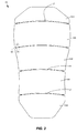
Figure 2 shows a rear view of a wearable protection device according to an embodiment of the present disclosure; -
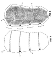
Figures 3 and 4 show, respectively, a rear view and front view of a wearable protection device according to an embodiment of the present disclosure in an operating condition; -
Figures 5 and 6 show, respectively, a rear view and front view of a wearable protection device according to an embodiment of the present disclosure in an operating condition; -
Figure 7 shows a front view of a wearable protection device according to an embodiment of the present disclosure; -
Figure 8 shows a cross-sectional view along the line VIII-VIII ofFigure 7 ; -
Figure 9 shows a rear view of a garment including a wearable protection device according to an embodiment of the present disclosure; -
Figure 10 shows a front view of a garment including a wearable protection device according to an embodiment of the present disclosure; -
Figure 11 shows a front view of a garment including a wearable protection device according to an embodiment of the present disclosure in an operating condition; -
Figure 12 shows a cross-sectional view along the line XII-XII ofFigure 11 . - With reference to the accompanying figures, the
reference number wearable protection device - In the embodiment shown, the
wearable protection device - The
back shield back shield 110, shown by way of example inFigures 9 to 12 , is incorporated in agarment 120 or is associated with a garment, for example a motorcyclist's jacket or suit, as will be described below. - In both embodiments, the
back shield adjacent plate members protection front surface 13. Theprotection front surface 13 is adapted to face an impact, namely conventionally is directed outwardly with respect to a user. - The
plate members pins 40, only one of which is shown by way of example inFigure 1 , said pins allowing theplate members Figures 5 and 6 . - The
plate members elastic elements 42 which allow theplate members longitudinal direction 15 and also to return into their original position at the end of a body movement. - Even more particularly, the
plate members longitudinal direction 15 on the side where saidprotection front surface 13 is situated. In particular, afirst plate member 12a of saidplate members portion 16 which overlaps thefront surface 13 of acorresponding portion 19 of asecond plate member 12b adjacent thereto. In other words, it can be seen that theportion 16 of thefirst plate member 12a is superposed on thecorresponding portion 19 on the outside, namely on the side where saidprotection front surface 13 is situated. Expressed in yet other words, the overlapping zone is arranged on the side where saidprotection front surface 13 is situated and therefore consists of an overlapping arrangement on the outer side of thewearable protection device - In the example shown, the
portion 16 is fin-shaped or lobe-shaped and, when viewed from the side where saidfront surface 13 is situated, has a smaller width compared to thesecond plate member 12b which it overlaps. - A discontinuity or
boundary zone 18 is therefore defined between a fin-like portion 16 of thefirst plate member 12a and theadjacent plate member 12b, wherein saiddiscontinuity zone 18 is located on theprotection front surface 13 of thesecond plate member 12b. In other words, as a result of overlapping on the outer side between theadjacent plate members adjacent plate members second plate member 12b, namely on the aforementionedcorresponding portion 19 of thesecond plate member 12b. The term "discontinuity zone" 18 is understood as meaning an empty space or physical separation in the boundary zone between the fin-like portion 16 of thefirst plate member 12a and thesecond plate member 12b. - In the example of embodiment shown, as can be seen in
Figures 8 and12 , thefin portion 16 of thefirst member 12a has a lower height than a remaining part of the respectivefirst plate member 12b and is therefore suitable for being superposed on acorresponding portion 19 of saidsecond plate member 12b which has a lower height than a remaining part of said second plate member 12b. Saidcorresponding portion 19 defines a seat for receiving the fin-like portion 16 of thefirst plate member 12a. - It should be noted, moreover, that, owing to the lower height of the fin-
like portion 16 and thecorresponding portion 19, all theplate members protection front surface 13 lies substantially in the same plane. - The
back shield pads plate members protection front surface 13, namely conventionally on the inner side of the back shield, namely on the inner side facing the user. Each of saidplate members corresponding pad pads respective plate members - Essentially, one
pad pads plate members pad pads pads surface discontinuity 17 with an adjacent pad. The term "surface discontinuity" 17 is understood as meaning an empty space or physical separation in the boundary zone between apad 14a and theadjacent pad 14b. - According to a further aspect of the present disclosure, in order to ensure effective protection on the part of the wearable protection device, without the presence of a
discontinuity zone 18 betweenadjacent plate members surface discontinuity 17 betweenadjacent pads device adjacent pads longitudinal direction 15 with respect to thesurface discontinuity zone 18 between said fin-like portion 16 of thefirst plate member 12a and the correspondingportion 19 of the secondadjacent plate member 12b. This offset arrangement is visible inFigures 8 and12 . - Essentially, it can be seen that, by means of this offset arrangement along the
longitudinal direction 15, asurface discontinuity zone 17 betweenadjacent pads like portion 16 of aplate member 12a. In fact the fin-like portion 16 extends in the manner of bridge over thesurface discontinuity zone 17 betweenadjacent pads - Furthermore, a
discontinuity zone 18 betweenadjacent plate members portion 19 of thesecond plate member 12b and by theunderlying pad 14b. - In other words, the
surface discontinuity 17 betweenadjacent pads like portion 16 of aplate member 12a, and thediscontinuity zone 18 betweenadjacent plate members second plate member 12b and by theunderlying pad 14b. - The arrangement of the
plate members respective pads Figures 3-4 and5-6 , both theplate members pads - At the same time, effective protection is ensured, also when the
plate members pads surface discontinuity 17 betweenpads discontinuity zone 18 between theplate members discontinuity zone 17 between thepads Figure 8 ) which may distribute the impact force both on thefirst plate member 12a and, owing to the overlapping zone, on thesecond plate member 12b. This distributing action is furthermore favoured by the fin profile of the fin-like portion 16 itself, since the impact may be distributed on thesecond plate member 12b along the (right-hand and left-hand) sides of the fin-like portion 16. In fact thesecond plate member 12b in actual fact surrounds the fin-like portion 16. - Moreover, should an impact occur in a zone corresponding to a discontinuity zone between the
plate members portion 19 of thesecond plate member 12b is also present. - In the embodiment shown, each of the
plate members ribs 30 which extend over saidprotection front surface 13. The ribs have a reinforcing function. In the embodiment shown, theribs 30 have a pattern which follows a profile of said fin-like portion 16 of thefirst plate member 12a, namely a U-shape or wave portion shape. This pattern allows the distribution of the impact forces to be guided along therespective plate member - In fact, should an impact occur along a boundary zone of the fin-
like portion 16, owing to the fact that the ribs follow the profile of the fin-like portion 16, it is possible to obtain a distribution of the impact along the entire surface of the correspondingfirst plate member 12a. - With reference to
Figures 7 to 10 , these show agarment 120 which incorporates the aforementionedwearable protection device 110. Thegarment 120 includes a clothing item taking the form, in the example of embodiment, of a waistcoat which acts as a support for the plurality ofplate members pads - In particular, the
plate members elastic elements 42 may be dispensed with. In this embodiment also, in order to favour the lateral rotational movement, pins 40 are provided. - The subject of the present disclosure has been described hitherto with reference to preferred embodiments thereof. It is understood that other embodiments relating to the same inventive idea may exist, all of these falling within the scope of protection of the claims which are provided hereinbelow.
Claims (17)
- Wearable protection device (10, 110) comprising a plurality of plate members (12a, 12b) adjacent in a side-by-side configuration so as to define a protection front surface, or side, (13) adapted to face an impact (I), wherein pairs of said plate members (12a, 12b) at least partially overlap each other along a longitudinal direction (15) by means of superposition of a portion (16) of a first plate member (12a) of said plate members (12a, 12b) on a front surface (13) of a corresponding portion (19) of a second plate member (12b) adjacent in the side-by-side configuration, so as to define a zone of surface discontinuity (18) between adjacent plate members (12a, 12b) on the front surface (13) of said second plate member (12b), said device comprising a plurality of pads (14a, 14b) each of said pads being associated with one of said plate members (12a, 12b) on an opposite side with respect to said protection front surface (13), characterised in that a first pad (14a) associated with the first plate member (12a) is structurally separate from a second pad (14b) associated with the second plate member (12b) so as to define a surface discontinuity or boundary zone (17) between adjacent first pad (14a) associated with the first plate member (12a) and second pad (14b) associated with the second plate member (12b), wherein said surface discontinuity (17) or boundary zone between adjacent first and second pads (14a, 14b) is offset along said longitudinal direction (15) with respect to the zone of surface discontinuity (18) between adjacent plate members (12a, 12b).
- Wearable protection device (10, 110) according to claim 1, wherein said portion (16) of a first plate member (12a) overlaps in the manner of a bridge said surface discontinuity (17) between adjacent pads (14a, 14b).
- Wearable protection device (10, 110) according to claim 2, wherein said portion (16) of the first plate member (12a) has a lower height than a remaining part of the respective first plate member (12a) and said corresponding portion (19) of said second plate member (12b) has a lower height than a remaining part of said second plate member (12b) and defines a seat for receiving said portion (16) of the first plate member (12a).
- Wearable protection device (10, 110) according to any one of the preceding claims, wherein said portion (16) of the first plate member (12a) is a fin-shaped or lobe-shaped.
- Wearable protection device (10, 110) according to claims 3 and 4, wherein said portion (16) of the first plate member (12a), when viewed from said protection front surface (13), has a smaller width compared to the second plate member (12b) such that said second plate member (12b) laterally surrounds said portion (16) of the first plate member (12a).
- Wearable protection device (10, 110) according to any one of the preceding claims, comprising a plurality of ribs associated with each of said plate members (12a, 12b) on said protection front surface (13).
- Wearable protection device (10, 110) according to any one of the preceding claims, wherein said ribs extend with a pattern which follows a profile, or free edge, of said portion (16) of said first plate member (12a).
- Wearable protection device (10, 110) according to any one of the preceding claims, wherein each rib is U-shaped or shaped as a wave portion.
- Wearable protection device (10, 110) according to any one of the preceding claims, wherein pairs of said plate members (12a, 12b) are bound together by means of a pin element (40).
- Wearable protection device (10, 110) according to any one of the preceding claims, comprising elastic connecting elements (42) which connect said plate members (12a, 12b).
- Wearable protection device (10, 110) according to claim 10, wherein said elastic connecting elements (42) are elements individually distinct from one another, each elastic connecting element being located between adjacent plate members (12a, 12b).
- Wearable protection device (10, 110) according to any one of the preceding claims, wherein said wearable device (10, 110) is a spine protector adapted to protect at least a portion of the spine of a user.
- Garment (120) comprising at least one wearable protection device (10, 110) according to any one of claims 1 to 12.
- Garment (120) according to claim 13, said garment (120) including a clothing item, and wherein said wearable protection device (110) is included in a fixed way in said clothing item.
- Garment (120) according to claim 14, wherein said plate members (12a, 12b) are arranged on an outer side of said clothing item and said pads (14a, 14b) are arranged on an inner side of said clothing item.
- Garment according to claim 15, wherein said clothing item is made of elastic material and acts as a resilient element for connecting adjacent plate members (12a, 12b).
- Wearable protection device (10, 110) according to any one of the preceding claims 1 to 12, wherein both the plate members (12a, 12b) and the pads (14a, 14b) may move away from and towards the adjacent plate members (12a, 12b) and the adjacent pads (14a, 14b) respectively.
Applications Claiming Priority (2)
| Application Number | Priority Date | Filing Date | Title |
|---|---|---|---|
| IT000114A ITVR20120114A1 (en) | 2012-06-05 | 2012-06-05 | WEARABLE PROTECTIVE DEVICE. |
| PCT/IB2013/054476 WO2013182959A1 (en) | 2012-06-05 | 2013-05-30 | Wearable protection device |
Publications (2)
| Publication Number | Publication Date |
|---|---|
| EP2854580A1 EP2854580A1 (en) | 2015-04-08 |
| EP2854580B1 true EP2854580B1 (en) | 2016-03-09 |
Family
ID=46727489
Family Applications (1)
| Application Number | Title | Priority Date | Filing Date |
|---|---|---|---|
| EP13737416.1A Active EP2854580B1 (en) | 2012-06-05 | 2013-05-30 | Wearable protection device |
Country Status (5)
| Country | Link |
|---|---|
| US (1) | US9232825B2 (en) |
| EP (1) | EP2854580B1 (en) |
| ES (1) | ES2573281T3 (en) |
| IT (1) | ITVR20120114A1 (en) |
| WO (1) | WO2013182959A1 (en) |
Families Citing this family (12)
| Publication number | Priority date | Publication date | Assignee | Title |
|---|---|---|---|---|
| US10524522B2 (en) * | 2013-04-22 | 2020-01-07 | D.H. Anderson Holdings Inc. | Body protector |
| MY170466A (en) * | 2013-12-10 | 2019-08-02 | Cleary Dolcetti Joseph | Exercise weights |
| US9908027B2 (en) | 2014-04-22 | 2018-03-06 | Nike, Inc. | Article of apparel with dynamic padding system |
| US20170049163A1 (en) * | 2015-03-02 | 2017-02-23 | Spencer Koroly | Wearable protective system and method for making the same |
| DE102016203780A1 (en) * | 2016-03-08 | 2017-09-14 | Bauerfeind Ag | Flexible support element for an orthosis |
| US10668356B2 (en) * | 2016-07-29 | 2020-06-02 | Elwha Llc | Protective garment systems for protecting an individual and methods of using the same |
| US10271591B2 (en) * | 2016-07-29 | 2019-04-30 | Elwha Llc | Protective garment systems for protecting an individual and methods of using the same |
| US10757991B2 (en) * | 2017-02-13 | 2020-09-01 | Richard Patz | Emblem and assembly for wearable clothing |
| US11123214B2 (en) * | 2017-09-11 | 2021-09-21 | Peter Wilson | Back-brace assistive device |
| IT201900014466A1 (en) | 2019-08-08 | 2021-02-08 | Giorgia Daniel | "Improved Protective Accessory" |
| KR102630159B1 (en) * | 2021-07-16 | 2024-01-29 | 최준혁 | Upper garment with customized spine support device |
| GB2637893A (en) * | 2022-06-08 | 2025-08-13 | Armaros Ltd | An Item of Clothing and an Insert for an Item of Clothing |
Family Cites Families (12)
| Publication number | Priority date | Publication date | Assignee | Title |
|---|---|---|---|---|
| EP0212206A1 (en) * | 1985-08-02 | 1987-03-04 | Adolf Weigl | Spine protection device against accidents |
| US4692946A (en) * | 1986-07-31 | 1987-09-15 | George Frost Company | Baseball catcher's leg guard |
| DE3935828A1 (en) * | 1989-10-27 | 1991-05-02 | Gericke Hein Gmbh Co Kg | SPINE PILLAR, IN PARTICULAR AS ACCIDENT PROTECTION FOR MOTORCYCLISTS |
| CA2091140C (en) * | 1993-03-05 | 2003-01-28 | Frank Arnold Kapounek | Spine protector |
| GB9309253D0 (en) * | 1993-05-05 | 1993-06-16 | Le Sueur Alexandra C | Improved body protector |
| US5400801A (en) * | 1993-12-06 | 1995-03-28 | Entropy Racing | Back guard |
| IT243480Y1 (en) * | 1997-07-24 | 2002-03-04 | Dainese Spa | BACK PROTECTOR IN PARTICULAR FOR MOTORCYCLISTS. |
| ITTV20010113A1 (en) * | 2001-08-10 | 2003-02-10 | Alpinestars Res Srl | FREELY JOINTED PROTECTION DEVICE AGAINST BACK IMPACTS |
| US7188370B2 (en) * | 2004-05-07 | 2007-03-13 | Nike Inc. | Protective device |
| US8161569B2 (en) * | 2007-07-25 | 2012-04-24 | Sport Maska Inc. | Core assembly for an athletic protective pad |
| US8082602B2 (en) * | 2008-08-15 | 2011-12-27 | Sport Maska Inc. | Upper body protective garment |
| DE102010005939A1 (en) * | 2010-01-26 | 2011-07-28 | Lanz, Philipp, Dr. | back protector |
-
2012
- 2012-06-05 IT IT000114A patent/ITVR20120114A1/en unknown
-
2013
- 2013-05-30 EP EP13737416.1A patent/EP2854580B1/en active Active
- 2013-05-30 ES ES13737416.1T patent/ES2573281T3/en active Active
- 2013-05-30 WO PCT/IB2013/054476 patent/WO2013182959A1/en not_active Ceased
- 2013-05-30 US US14/403,118 patent/US9232825B2/en active Active
Also Published As
| Publication number | Publication date |
|---|---|
| US9232825B2 (en) | 2016-01-12 |
| ITVR20120114A1 (en) | 2013-12-06 |
| US20150164154A1 (en) | 2015-06-18 |
| ES2573281T3 (en) | 2016-06-07 |
| EP2854580A1 (en) | 2015-04-08 |
| WO2013182959A1 (en) | 2013-12-12 |
Similar Documents
| Publication | Publication Date | Title |
|---|---|---|
| US9232825B2 (en) | Wearable protection device | |
| US8082602B2 (en) | Upper body protective garment | |
| US7743429B2 (en) | Protective device | |
| CA2822529C (en) | Protective garment with rib cushioning pads | |
| US6874170B1 (en) | Head and neck protection system | |
| EP2323508B1 (en) | Glove structure, in particular for motorcycling sector | |
| EP1042966B1 (en) | A padded glove for protecting and positioning the hand of a wearer | |
| US20140165272A1 (en) | Covering structure of liners of bike pants | |
| JP7792373B2 (en) | Catcher's leg guard | |
| EP2229828B1 (en) | Wearable protection device | |
| EP1838398A1 (en) | Neck protective device | |
| US20050102741A1 (en) | Protective athletic garment | |
| US8370968B2 (en) | Cervical spine protection device | |
| EP1976602B1 (en) | Anatomical forearm protection. | |
| US7900284B2 (en) | Garment for sporting activity | |
| US11178919B2 (en) | Garment for motorcyclists | |
| GB2449268A (en) | Knee protectors | |
| WO2022269450A1 (en) | Protective garment for articulations of the human body | |
| EP2632284A2 (en) | Structure for protecting of the back | |
| JPH11241206A (en) | Backbone pad | |
| KR20130015030A (en) | Joint protector | |
| JP4834117B2 (en) | Baseball calf pad | |
| EP2974608B1 (en) | Protective glove | |
| WO2026093928A1 (en) | Protective garment for articulations of the human body | |
| US20170080321A1 (en) | Shoulder pads with head and neck protection |
Legal Events
| Date | Code | Title | Description |
|---|---|---|---|
| PUAI | Public reference made under article 153(3) epc to a published international application that has entered the european phase |
Free format text: ORIGINAL CODE: 0009012 |
|
| 17P | Request for examination filed |
Effective date: 20141204 |
|
| AK | Designated contracting states |
Kind code of ref document: A1 Designated state(s): AL AT BE BG CH CY CZ DE DK EE ES FI FR GB GR HR HU IE IS IT LI LT LU LV MC MK MT NL NO PL PT RO RS SE SI SK SM TR |
|
| AX | Request for extension of the european patent |
Extension state: BA ME |
|
| RAP1 | Party data changed (applicant data changed or rights of an application transferred) |
Owner name: NEW D S.P.A. |
|
| RAP1 | Party data changed (applicant data changed or rights of an application transferred) |
Owner name: DAINESE S.P.A. |
|
| GRAP | Despatch of communication of intention to grant a patent |
Free format text: ORIGINAL CODE: EPIDOSNIGR1 |
|
| DAX | Request for extension of the european patent (deleted) | ||
| INTG | Intention to grant announced |
Effective date: 20150826 |
|
| GRAS | Grant fee paid |
Free format text: ORIGINAL CODE: EPIDOSNIGR3 |
|
| GRAA | (expected) grant |
Free format text: ORIGINAL CODE: 0009210 |
|
| AK | Designated contracting states |
Kind code of ref document: B1 Designated state(s): AL AT BE BG CH CY CZ DE DK EE ES FI FR GB GR HR HU IE IS IT LI LT LU LV MC MK MT NL NO PL PT RO RS SE SI SK SM TR |
|
| REG | Reference to a national code |
Ref country code: GB Ref legal event code: FG4D |
|
| REG | Reference to a national code |
Ref country code: AT Ref legal event code: REF Ref document number: 778798 Country of ref document: AT Kind code of ref document: T Effective date: 20160315 Ref country code: CH Ref legal event code: EP |
|
| REG | Reference to a national code |
Ref country code: IE Ref legal event code: FG4D |
|
| REG | Reference to a national code |
Ref country code: DE Ref legal event code: R096 Ref document number: 602013005429 Country of ref document: DE |
|
| REG | Reference to a national code |
Ref country code: FR Ref legal event code: PLFP Year of fee payment: 4 |
|
| REG | Reference to a national code |
Ref country code: CH Ref legal event code: NV Representative=s name: PATENTANWAELTE SCHAAD, BALASS, MENZL AND PARTN, CH |
|
| REG | Reference to a national code |
Ref country code: ES Ref legal event code: FG2A Ref document number: 2573281 Country of ref document: ES Kind code of ref document: T3 Effective date: 20160607 |
|
| REG | Reference to a national code |
Ref country code: LT Ref legal event code: MG4D |
|
| REG | Reference to a national code |
Ref country code: NL Ref legal event code: MP Effective date: 20160309 |
|
| PG25 | Lapsed in a contracting state [announced via postgrant information from national office to epo] |
Ref country code: GR Free format text: LAPSE BECAUSE OF FAILURE TO SUBMIT A TRANSLATION OF THE DESCRIPTION OR TO PAY THE FEE WITHIN THE PRESCRIBED TIME-LIMIT Effective date: 20160610 Ref country code: NO Free format text: LAPSE BECAUSE OF FAILURE TO SUBMIT A TRANSLATION OF THE DESCRIPTION OR TO PAY THE FEE WITHIN THE PRESCRIBED TIME-LIMIT Effective date: 20160609 Ref country code: FI Free format text: LAPSE BECAUSE OF FAILURE TO SUBMIT A TRANSLATION OF THE DESCRIPTION OR TO PAY THE FEE WITHIN THE PRESCRIBED TIME-LIMIT Effective date: 20160309 Ref country code: HR Free format text: LAPSE BECAUSE OF FAILURE TO SUBMIT A TRANSLATION OF THE DESCRIPTION OR TO PAY THE FEE WITHIN THE PRESCRIBED TIME-LIMIT Effective date: 20160309 |
|
| PG25 | Lapsed in a contracting state [announced via postgrant information from national office to epo] |
Ref country code: LT Free format text: LAPSE BECAUSE OF FAILURE TO SUBMIT A TRANSLATION OF THE DESCRIPTION OR TO PAY THE FEE WITHIN THE PRESCRIBED TIME-LIMIT Effective date: 20160309 Ref country code: NL Free format text: LAPSE BECAUSE OF FAILURE TO SUBMIT A TRANSLATION OF THE DESCRIPTION OR TO PAY THE FEE WITHIN THE PRESCRIBED TIME-LIMIT Effective date: 20160309 Ref country code: RS Free format text: LAPSE BECAUSE OF FAILURE TO SUBMIT A TRANSLATION OF THE DESCRIPTION OR TO PAY THE FEE WITHIN THE PRESCRIBED TIME-LIMIT Effective date: 20160309 Ref country code: BE Free format text: LAPSE BECAUSE OF NON-PAYMENT OF DUE FEES Effective date: 20160531 Ref country code: LV Free format text: LAPSE BECAUSE OF FAILURE TO SUBMIT A TRANSLATION OF THE DESCRIPTION OR TO PAY THE FEE WITHIN THE PRESCRIBED TIME-LIMIT Effective date: 20160309 Ref country code: PL Free format text: LAPSE BECAUSE OF FAILURE TO SUBMIT A TRANSLATION OF THE DESCRIPTION OR TO PAY THE FEE WITHIN THE PRESCRIBED TIME-LIMIT Effective date: 20160309 Ref country code: SE Free format text: LAPSE BECAUSE OF FAILURE TO SUBMIT A TRANSLATION OF THE DESCRIPTION OR TO PAY THE FEE WITHIN THE PRESCRIBED TIME-LIMIT Effective date: 20160309 |
|
| PG25 | Lapsed in a contracting state [announced via postgrant information from national office to epo] |
Ref country code: EE Free format text: LAPSE BECAUSE OF FAILURE TO SUBMIT A TRANSLATION OF THE DESCRIPTION OR TO PAY THE FEE WITHIN THE PRESCRIBED TIME-LIMIT Effective date: 20160309 Ref country code: IS Free format text: LAPSE BECAUSE OF FAILURE TO SUBMIT A TRANSLATION OF THE DESCRIPTION OR TO PAY THE FEE WITHIN THE PRESCRIBED TIME-LIMIT Effective date: 20160709 |
|
| PG25 | Lapsed in a contracting state [announced via postgrant information from national office to epo] |
Ref country code: SK Free format text: LAPSE BECAUSE OF FAILURE TO SUBMIT A TRANSLATION OF THE DESCRIPTION OR TO PAY THE FEE WITHIN THE PRESCRIBED TIME-LIMIT Effective date: 20160309 Ref country code: RO Free format text: LAPSE BECAUSE OF FAILURE TO SUBMIT A TRANSLATION OF THE DESCRIPTION OR TO PAY THE FEE WITHIN THE PRESCRIBED TIME-LIMIT Effective date: 20160309 Ref country code: SM Free format text: LAPSE BECAUSE OF FAILURE TO SUBMIT A TRANSLATION OF THE DESCRIPTION OR TO PAY THE FEE WITHIN THE PRESCRIBED TIME-LIMIT Effective date: 20160309 Ref country code: CZ Free format text: LAPSE BECAUSE OF FAILURE TO SUBMIT A TRANSLATION OF THE DESCRIPTION OR TO PAY THE FEE WITHIN THE PRESCRIBED TIME-LIMIT Effective date: 20160309 Ref country code: PT Free format text: LAPSE BECAUSE OF FAILURE TO SUBMIT A TRANSLATION OF THE DESCRIPTION OR TO PAY THE FEE WITHIN THE PRESCRIBED TIME-LIMIT Effective date: 20160711 |
|
| REG | Reference to a national code |
Ref country code: DE Ref legal event code: R097 Ref document number: 602013005429 Country of ref document: DE |
|
| PG25 | Lapsed in a contracting state [announced via postgrant information from national office to epo] |
Ref country code: LU Free format text: LAPSE BECAUSE OF FAILURE TO SUBMIT A TRANSLATION OF THE DESCRIPTION OR TO PAY THE FEE WITHIN THE PRESCRIBED TIME-LIMIT Effective date: 20160530 Ref country code: BE Free format text: LAPSE BECAUSE OF FAILURE TO SUBMIT A TRANSLATION OF THE DESCRIPTION OR TO PAY THE FEE WITHIN THE PRESCRIBED TIME-LIMIT Effective date: 20160309 |
|
| PLBE | No opposition filed within time limit |
Free format text: ORIGINAL CODE: 0009261 |
|
| STAA | Information on the status of an ep patent application or granted ep patent |
Free format text: STATUS: NO OPPOSITION FILED WITHIN TIME LIMIT |
|
| PG25 | Lapsed in a contracting state [announced via postgrant information from national office to epo] |
Ref country code: DK Free format text: LAPSE BECAUSE OF FAILURE TO SUBMIT A TRANSLATION OF THE DESCRIPTION OR TO PAY THE FEE WITHIN THE PRESCRIBED TIME-LIMIT Effective date: 20160309 |
|
| 26N | No opposition filed |
Effective date: 20161212 |
|
| REG | Reference to a national code |
Ref country code: IE Ref legal event code: MM4A |
|
| PG25 | Lapsed in a contracting state [announced via postgrant information from national office to epo] |
Ref country code: BG Free format text: LAPSE BECAUSE OF FAILURE TO SUBMIT A TRANSLATION OF THE DESCRIPTION OR TO PAY THE FEE WITHIN THE PRESCRIBED TIME-LIMIT Effective date: 20160609 |
|
| REG | Reference to a national code |
Ref country code: FR Ref legal event code: PLFP Year of fee payment: 5 |
|
| PG25 | Lapsed in a contracting state [announced via postgrant information from national office to epo] |
Ref country code: IE Free format text: LAPSE BECAUSE OF NON-PAYMENT OF DUE FEES Effective date: 20160530 Ref country code: SI Free format text: LAPSE BECAUSE OF FAILURE TO SUBMIT A TRANSLATION OF THE DESCRIPTION OR TO PAY THE FEE WITHIN THE PRESCRIBED TIME-LIMIT Effective date: 20160309 |
|
| REG | Reference to a national code |
Ref country code: AT Ref legal event code: UEP Ref document number: 778798 Country of ref document: AT Kind code of ref document: T Effective date: 20160309 |
|
| PG25 | Lapsed in a contracting state [announced via postgrant information from national office to epo] |
Ref country code: HU Free format text: LAPSE BECAUSE OF FAILURE TO SUBMIT A TRANSLATION OF THE DESCRIPTION OR TO PAY THE FEE WITHIN THE PRESCRIBED TIME-LIMIT; INVALID AB INITIO Effective date: 20130530 |
|
| REG | Reference to a national code |
Ref country code: FR Ref legal event code: PLFP Year of fee payment: 6 |
|
| PG25 | Lapsed in a contracting state [announced via postgrant information from national office to epo] |
Ref country code: MC Free format text: LAPSE BECAUSE OF FAILURE TO SUBMIT A TRANSLATION OF THE DESCRIPTION OR TO PAY THE FEE WITHIN THE PRESCRIBED TIME-LIMIT Effective date: 20160309 Ref country code: MK Free format text: LAPSE BECAUSE OF FAILURE TO SUBMIT A TRANSLATION OF THE DESCRIPTION OR TO PAY THE FEE WITHIN THE PRESCRIBED TIME-LIMIT Effective date: 20160309 Ref country code: CY Free format text: LAPSE BECAUSE OF FAILURE TO SUBMIT A TRANSLATION OF THE DESCRIPTION OR TO PAY THE FEE WITHIN THE PRESCRIBED TIME-LIMIT Effective date: 20160309 Ref country code: MT Free format text: LAPSE BECAUSE OF NON-PAYMENT OF DUE FEES Effective date: 20160531 |
|
| PG25 | Lapsed in a contracting state [announced via postgrant information from national office to epo] |
Ref country code: TR Free format text: LAPSE BECAUSE OF FAILURE TO SUBMIT A TRANSLATION OF THE DESCRIPTION OR TO PAY THE FEE WITHIN THE PRESCRIBED TIME-LIMIT Effective date: 20160309 Ref country code: AL Free format text: LAPSE BECAUSE OF FAILURE TO SUBMIT A TRANSLATION OF THE DESCRIPTION OR TO PAY THE FEE WITHIN THE PRESCRIBED TIME-LIMIT Effective date: 20160309 |
|
| REG | Reference to a national code |
Ref country code: DE Ref legal event code: R081 Ref document number: 602013005429 Country of ref document: DE Owner name: DAINESE S.P.A., COLCERESA, IT Free format text: FORMER OWNER: DAINESE S.P.A., MOLVENA, VICENZA, IT Ref country code: DE Ref legal event code: R082 Ref document number: 602013005429 Country of ref document: DE Representative=s name: SIB SOCIETA ITALIANA BREVETTI S.P.A., IT |
|
| REG | Reference to a national code |
Ref country code: DE Ref legal event code: R082 Ref document number: 602013005429 Country of ref document: DE |
|
| PGFP | Annual fee paid to national office [announced via postgrant information from national office to epo] |
Ref country code: GB Payment date: 20230524 Year of fee payment: 11 |
|
| PGFP | Annual fee paid to national office [announced via postgrant information from national office to epo] |
Ref country code: DE Payment date: 20240521 Year of fee payment: 12 |
|
| PGFP | Annual fee paid to national office [announced via postgrant information from national office to epo] |
Ref country code: CH Payment date: 20240602 Year of fee payment: 12 |
|
| PGFP | Annual fee paid to national office [announced via postgrant information from national office to epo] |
Ref country code: ES Payment date: 20240627 Year of fee payment: 12 |
|
| PGFP | Annual fee paid to national office [announced via postgrant information from national office to epo] |
Ref country code: AT Payment date: 20240522 Year of fee payment: 12 |
|
| GBPC | Gb: european patent ceased through non-payment of renewal fee |
Effective date: 20240530 |
|
| PG25 | Lapsed in a contracting state [announced via postgrant information from national office to epo] |
Ref country code: GB Free format text: LAPSE BECAUSE OF NON-PAYMENT OF DUE FEES Effective date: 20240530 |
|
| PGFP | Annual fee paid to national office [announced via postgrant information from national office to epo] |
Ref country code: IT Payment date: 20250505 Year of fee payment: 13 |
|
| PGFP | Annual fee paid to national office [announced via postgrant information from national office to epo] |
Ref country code: FR Payment date: 20250528 Year of fee payment: 13 |
|
| REG | Reference to a national code |
Ref country code: DE Ref legal event code: R119 Ref document number: 602013005429 Country of ref document: DE |
|
| REG | Reference to a national code |
Ref country code: CH Ref legal event code: H13 Free format text: ST27 STATUS EVENT CODE: U-0-0-H10-H13 (AS PROVIDED BY THE NATIONAL OFFICE) Effective date: 20251223 |
|
| PG25 | Lapsed in a contracting state [announced via postgrant information from national office to epo] |
Ref country code: AT Free format text: LAPSE BECAUSE OF NON-PAYMENT OF DUE FEES Effective date: 20250530 |
|
| REG | Reference to a national code |
Ref country code: AT Ref legal event code: MM01 Ref document number: 778798 Country of ref document: AT Kind code of ref document: T Effective date: 20250530 |
|
| PG25 | Lapsed in a contracting state [announced via postgrant information from national office to epo] |
Ref country code: CH Free format text: LAPSE BECAUSE OF NON-PAYMENT OF DUE FEES Effective date: 20250531 |
|
| PG25 | Lapsed in a contracting state [announced via postgrant information from national office to epo] |
Ref country code: DE Free format text: LAPSE BECAUSE OF NON-PAYMENT OF DUE FEES Effective date: 20251202 |