EP2854338A1 - Method to operate a network unit for generating test traffic - Google Patents
Method to operate a network unit for generating test traffic Download PDFInfo
- Publication number
- EP2854338A1 EP2854338A1 EP20130290231 EP13290231A EP2854338A1 EP 2854338 A1 EP2854338 A1 EP 2854338A1 EP 20130290231 EP20130290231 EP 20130290231 EP 13290231 A EP13290231 A EP 13290231A EP 2854338 A1 EP2854338 A1 EP 2854338A1
- Authority
- EP
- European Patent Office
- Prior art keywords
- message entity
- unit
- message
- network
- entity
- Prior art date
- Legal status (The legal status is an assumption and is not a legal conclusion. Google has not performed a legal analysis and makes no representation as to the accuracy of the status listed.)
- Granted
Links
- 238000000034 method Methods 0.000 title claims abstract description 25
- 238000012360 testing method Methods 0.000 title description 6
- 238000012546 transfer Methods 0.000 claims abstract description 12
- 238000012545 processing Methods 0.000 claims description 47
- 230000005540 biological transmission Effects 0.000 claims description 9
- 230000003139 buffering effect Effects 0.000 claims 2
- 238000000926 separation method Methods 0.000 description 10
- 230000006870 function Effects 0.000 description 8
- 230000008901 benefit Effects 0.000 description 3
- 238000005259 measurement Methods 0.000 description 2
- 230000004048 modification Effects 0.000 description 2
- 238000012986 modification Methods 0.000 description 2
- 230000003287 optical effect Effects 0.000 description 2
- 230000009471 action Effects 0.000 description 1
- 230000008859 change Effects 0.000 description 1
- 230000003111 delayed effect Effects 0.000 description 1
- 238000005516 engineering process Methods 0.000 description 1
- 239000004744 fabric Substances 0.000 description 1
- 238000011065 in-situ storage Methods 0.000 description 1
- 230000008569 process Effects 0.000 description 1
- 230000010076 replication Effects 0.000 description 1
- 238000007493 shaping process Methods 0.000 description 1
Images


Classifications
-
- H—ELECTRICITY
- H04—ELECTRIC COMMUNICATION TECHNIQUE
- H04L—TRANSMISSION OF DIGITAL INFORMATION, e.g. TELEGRAPHIC COMMUNICATION
- H04L43/00—Arrangements for monitoring or testing data switching networks
- H04L43/50—Testing arrangements
Definitions
- the invention relates to a method to operate a network unit of a message entity transfer network.
- test traffic is an integral part of approval and regular tests of networks and its services. These networks are subjected to this test traffic to evaluate whether certain functions of the network comply with specified properties, e.g. quality of service.
- this object is achieved in that a first message entity is circulated and a second message entity is emitted depending on the first message entity from a network unit to a message entity transfer network.
- the second message entity is emitted according to the first message entity circulating a respective network unit does not have to provide a large memory, especially large memory of a traffic generator, or sophisticated circuitry for traffic generation. Furthermore it is possible to use the existing infrastructure without further equipment. Also sophisticated traffic shaping methods are not required any more what advantageously maintains the integrity of the message entity flow, e.g. sequence numbers or the payload are maintained.
- the required artificial network traffic according to the second message entity is generated in situ by using the existing range of functions in parallel to the egress and/or ingress traffic attended by the network unit. Moreover, due to this use of existing infrastructure in favour of separate commercial test equipment and the use of existing processing means, e.g. pipelines, the costs for traffic generation for network tests can be minimized.
- the first message entity is passed through a first processing unit in an ingress direction and through a second processing unit in an egress direction.
- the second message entity is emitted in the egress direction and/or the ingress direction.
- all message entity processing steps of the respective processing units are passed through. This allows the modification of the first message entity to a large extent.
- Another advantage is that the first message entity is subjected to all important packet editing steps. Especially the ingress part of the network unit comprises most of these important packet editing steps.
- the processing units alter the content of a header and/or of a payload of the first message entity.
- the first message entity and the second message entity are message entities according to level 2, 3 and/or 4 of the OSI model. This advantageously allows a modification of the first message entity also on higher levels as the media access control level.
- the second message entity is established each time the first message entity passes a generation unit. This replication of the first message entity allows the circulation of the first message entity and the traffic generation through the second message entity.
- the generation unit is arranged in the egress processing pipeline, the egress traffic manager, the ingress processing pipeline or the ingress traffic manager and therefore nearby the respective interface for emitting the second message entity. This reduces overhead regarding the treatment of the second message entity inside the network unit.
- the flow of the first message entity is controlled inside the network unit by means of a flow adjustment unit.
- this embodiment allows especially the control of the bandwidth of the traffic generated by the second message entity.
- the first message entity is buffered inside the network unit for a first time period by means of a first buffer, especially a circular buffer, of the flow adjustment unit.
- a first buffer especially a circular buffer
- it is provided to generate traffic with a slowed down rate of message entities per time period compared with the clocking domain of the further message entities.
- a further first message entity is buffered inside the network unit for a second time period by means of a second buffer, especially a circular buffer, of the flow adjustment unit.
- a second buffer especially a circular buffer
- a clock cycle for the transmission of the first message entity and the transmission of further message entities inside the network unit is changed by means of the flow adjustment unit.
- the rate of the emitted traffic is controlled.
- a set point flow value for the second message entity is applied.
- a current flow value of the first message entity is measured.
- the set point flow value and the current flow value are compared.
- a controller unit operates the flow adjustment unit depending on the comparison.
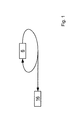
- Figure 1 is a schematic depiction of a method to operate a network unit of a message entity transfer network. It is circulated a first message entity 6 by means of respective circulation means. It is emitted a second message entity 16 depending on the first message entity 6 from the network unit to the message entity transfer network. Of course, a plurality of first message entities 6 may exist and circulate.
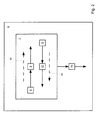
- Figure 2 is a schematic depiction of the network unit 2 of the message entity transfer network 4. It is passed the first message entity 6 through a first processing unit 8 of the network unit 2 in an ingress direction 10. It is passed the first message entity 6 through a second processing unit 12 of the network unit 2 in an egress direction 14. The second message entity 16 is emitted from the network unit 2 to the message entity transfer network 4 depending on the first message entity 6 in the egress direction 14 or the ingress direction 10.
- the methods proposed herein are conducted on a network unit 2 which is a Network Processor, a Line Card including the Network Processor or a Switching Unit comprising the Line Card.
- the first message entity 6 and further ingress traffic message entities, different from the first message entity 6, pass through the first processing unit 8 of the network unit 2 in the ingress direction 10.
- the first message entity 6 and further egress traffic message entities pass through the second processing unit 12 in the egress direction 14.
- the emission of the second message entity 16 and/or of a plurality of second message entities 16 constitutes artificial network traffic for an egress network and/or an ingress network.
- the second message entity 16 is emitted in the egress direction 14 to other network units of an egress network, for example a unit like the network unit 2.
- the second message entity 16 is emitted first from a first Line Card to an internal unit of for example the Switching Unit before entering a further egress network through another second Line Card of the Switching Unit, the internal unit representing an ingress network.
- second message entities 16 are emitted to an ingress network and an egress network.
- the exemplified method and the network unit 2 are applicable independently of the underlying transmission technology, e.g. optical or electrical transmission. Also mixed architectures with optical and electrical transmission techniques benefit from the presented teaching.
- Figure 3 is a more detailed schematic depiction of the network unit 2.
- the first message entity 6 is not shown in figure 3 .
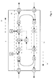
- the first message entity 6 circulates inside the network unit 2 according to the circle 18. Starting with the first processing unit 8 the first message entity 6 and further ingress traffic message entities are processed and forwarded from the first processing unit 8 to a first separation unit 20, wherein the first processing unit 8 can modify the passing message entities.
- the separation unit 20 forwards the further ingress traffic message entities to an ingress output port 22.
- the separation unit 20 forwards the first message entity 6 to a first combination unit 24.
- the first combination unit 24 combines egress traffic message entities from an egress input port 26 with the first message entity 6 and forwards these message entities to the second processing unit 12.
- the second processing unit 12 processes the received message entities and forwards the received message entities to a second separation unit 28.
- the second separation unit 28 forwards the first message entity 6 to a second combination unit 30 and forwards the further egress traffic message entities to an egress output port 32.
- the second combination unit 30 combines further ingress traffic message entities coming from an ingress input port 34 with the first message entity 6 coming from the separation unit 28 and forwards these message entities to the first processing unit 8.
- the first and second separation units 20 and 28 and the first and second combination units 24 and 30 are referred to as circulation means.
- the egress output port 22 and the egress input port 26 can be referred to as a first interface 36.
- the first interface 36 can be realized as a Fabric Interface Chip of a Line Card to be connected to a corresponding interface module of a Switch Fabric Card of a Switching Unit.
- the egress output port 32 and the ingress input port 34 can be referred to as a second interface 38.
- the second interface 38 can be realized as a Media Access Control Chip of a Line Card to be connected to the egress network.
- the creation of the first message entity 6 is outlined below to figure 4 .
- the circulation means may be arranged outside of the network unit 2.
- this further embodiment embraces a circulation of the first message entity 6 inside the network unit 2.
- the first processing unit 8 and/or the second processing unit 12 is configured to pass the received message entities and/or to alter the content of a header of the first message entity 6 and/or the payload of the first message entity 6.
- the first message entity 6 and the second message entity 16 are message entities according to level 2, 3 or 4 of the OSI model, especially to the standard ISO/IEC 7498-1. Consequently, even if the egress network or the ingress network only handles e.g. level 2 message entities, the first and/or second processing means 8, 12 is configured to alter the first message entity 6 on level 2, 3 and/or 4. Nevertheless, this aspect of processing the first message entity 6 does not interfere with the meaning of the term message entity transfer network 4.
- the second message entity 16 is established.
- the generation unit is preferably arranged closely to the emitting output port 22, 32.
- the generation unit is preferably located in the second processing unit 12 or the second separation unit 28.
- the generation unit is preferably located in the first processing unit 8 or the first separation unit 20.
- the second message entity 16 is treated inside the network element 2 like further ingress or egress traffic message entities, consequently leading to the emission of the second message entity 16.
- the generation unit can be switched on to generate the second message entity 16 every time the first message entity 6 passes the generation unit.
- the generation unit can be switched on only for a period of time.
- FIG. 4 is a further detailed schematic depiction of the network unit 2.
- the network unit 2 of figure 4 is configured to emit the second message entity 16 in the egress direction 14.
- the generation unit is arranged for example in an egress processing pipeline 40, an egress traffic manager 42 or the second separation unit 28.
- the egress traffic manager 42 and the egress processing pipeline 40 constitute the second processing unit 12.
- the generation unit establishes the second message entity 16 based on an identification, especially a VLAN address in the header of the first message entity 6.
- the network unit 2 comprises in a sequence an ingress processing pipeline 44, a flow adjustment unit 46 and an ingress traffic manager 48, altogether constituting the first processing unit 8.
- the flow adjustment unit 46 is part of the ingress processing pipeline 44 or according to a further embodiment the flow adjustment unit 46 is arranged at a further position on the path the first message entity 5 passes.
- the ingress processing pipeline 44 alters the header and/or the payload of the first message entity, e.g. a timestamp or a sequence number.
- traffic measurement inside the network unit 2 is conducted for example by the ingress traffic manager 48 and/or the egress traffic manager 42.
- the measurement result for example a message entity rate, is applied to a controller unit 50.
- the flow adjustment unit 46 controls the flow of the first message entity 6.
- the flow adjustment unit 46 may comprise a first buffer, especially a circular buffer, to buffer the first message entity 6 for a first time period.
- the flow adjustment unit 46 comprises the first buffer and a second buffer, especially a circular buffer, to buffer a further first message entity 6 for a second time period.
- the first and second time period may vary according to a respective function.
- controller unit 50 may instruct the flow adjustment unit 46 to change a clock cycle or clocking domain for the transmission of the first message entity 6 and the transmission of further message entities inside the network unit 2.
- the controller unit 50 can instruct the flow adjustment unit 46 to delay and/or speed up the first message entity 6 to result in traffic constituted by the second message entity 16 according to a respective function.
- This function may result in a constant flow of the first message entity 6.
- a probability distribution of first message entities over time may be selected.
- the burstiness of the generated traffic can be influenced by the flow adjustment unit 46 by influencing the probability distribution of first message entities 6 over a certain period of time in the form of a higher rate of message entities for that certain period of time.
- the first message entity 6 will be delayed or sped up to comply with a negative exponential distribution.
- a control scheme it is applied a set point flow value for the second message entity 16, e.g. a set point value for a message entity rate, a payload data rate or a set point function defining a probability distribution of the emission of second message entities 16 over time.
- a current flow value e.g. a current message entity rate or a current payload data rate, of the first message entity 6 is measured, for example by the ingress traffic manager 48 and/or the egress traffic manager 42.
- the set point flow value and the current flow value are compared.
- the controller unit 50 operates the flow adjustment unit 46 depending on the comparison.
- the traffic is not measured and the flow of the first message 6 is adjusted by means of the flow adjustment unit 46 depending on a pre-set value, e.g. a message entity rate, a payload data rate or function defining a probability distribution of the emission of second message entities 16 over time.
- a pre-set value e.g. a message entity rate, a payload data rate or function defining a probability distribution of the emission of second message entities 16 over time.
- the pre-set value is stored for example as a look-up table inside or outside the network unit 2.
- One or more first message entities 6 are injected into the circulation by a Central Processing Unit, CPU 52 between the second combination unit 30 and the ingress processing pipeline 44.
- CPU 52 Central Processing Unit
- the one or more first message entities can be injected into the circulation by the CPU 52 at another point in the circle.
- An external memory 54 is connected to the ingress traffic manager 48. If the network unit 2 is implemented as Network Processor the CPU 52 and the external memory 54 are external components according to an external area 56. The external memory 54 is used to buffer traffic which.
- Figure 5 is a schematic depiction of the control scheme for the network unit 2.
- the set point flow value 60 for the second message entity 16 is applied to the control unit 50.
- the current flow value 62 of the first message entity 6 is measured by the ingress traffic manager 48 and/or the egress traffic manager 42 and is applied to the control unit 50.
- a unit 63 determines a difference 66 between the set point flow value 60 and the current flow value 62 by comparing the set point flow value 60 and the current flow value 62. Based on the difference 66 a controller 68 determines a corrective action signal 70 which is applied to the flow adjustment unit 46.
- the controller unit 50 operates the flow adjustment unit 46 depending on the comparison.
- the operation of the flow adjustment unit 46 has impact on the flow 72 of the first message entity 6 inside the network unit 2.
Landscapes
- Engineering & Computer Science (AREA)
- Computer Networks & Wireless Communication (AREA)
- Signal Processing (AREA)
- Data Exchanges In Wide-Area Networks (AREA)
Abstract
Description
- The invention relates to a method to operate a network unit of a message entity transfer network.
- Generation of test traffic is an integral part of approval and regular tests of networks and its services. These networks are subjected to this test traffic to evaluate whether certain functions of the network comply with specified properties, e.g. quality of service.
- In view of the prior art, it is an object of the invention to provide an improved network unit which avoids the disadvantages of the prior art. According to an embodiment, this object is achieved in that a first message entity is circulated and a second message entity is emitted depending on the first message entity from a network unit to a message entity transfer network.
- As the second message entity is emitted according to the first message entity circulating a respective network unit does not have to provide a large memory, especially large memory of a traffic generator, or sophisticated circuitry for traffic generation. Furthermore it is possible to use the existing infrastructure without further equipment. Also sophisticated traffic shaping methods are not required any more what advantageously maintains the integrity of the message entity flow, e.g. sequence numbers or the payload are maintained. Advantageously the required artificial network traffic according to the second message entity is generated in situ by using the existing range of functions in parallel to the egress and/or ingress traffic attended by the network unit. Moreover, due to this use of existing infrastructure in favour of separate commercial test equipment and the use of existing processing means, e.g. pipelines, the costs for traffic generation for network tests can be minimized.
- According to a further embodiment the first message entity is passed through a first processing unit in an ingress direction and through a second processing unit in an egress direction. The second message entity is emitted in the egress direction and/or the ingress direction. Advantageously all message entity processing steps of the respective processing units are passed through. This allows the modification of the first message entity to a large extent. Another advantage is that the first message entity is subjected to all important packet editing steps. Especially the ingress part of the network unit comprises most of these important packet editing steps.
- According to a further embodiment the processing units alter the content of a header and/or of a payload of the first message entity. Furthermore, the first message entity and the second message entity are message entities according to
level 2, 3 and/or 4 of the OSI model. This advantageously allows a modification of the first message entity also on higher levels as the media access control level. - According to a further embodiment the second message entity is established each time the first message entity passes a generation unit. This replication of the first message entity allows the circulation of the first message entity and the traffic generation through the second message entity.
- According to a further embodiment the generation unit is arranged in the egress processing pipeline, the egress traffic manager, the ingress processing pipeline or the ingress traffic manager and therefore nearby the respective interface for emitting the second message entity. This reduces overhead regarding the treatment of the second message entity inside the network unit.
- According to a further embodiment the flow of the first message entity is controlled inside the network unit by means of a flow adjustment unit. Advantageously this embodiment allows especially the control of the bandwidth of the traffic generated by the second message entity.
- According to a further embodiment the first message entity is buffered inside the network unit for a first time period by means of a first buffer, especially a circular buffer, of the flow adjustment unit. Advantageously it is provided to generate traffic with a slowed down rate of message entities per time period compared with the clocking domain of the further message entities.
- According to a further embodiment a further first message entity is buffered inside the network unit for a second time period by means of a second buffer, especially a circular buffer, of the flow adjustment unit. This embodiment advantageously allows a traffic mix emitted from the network unit.
- According to a further embodiment a clock cycle for the transmission of the first message entity and the transmission of further message entities inside the network unit is changed by means of the flow adjustment unit. Advantageously the rate of the emitted traffic is controlled.
- According to a further embodiment a set point flow value for the second message entity is applied. A current flow value of the first message entity is measured. The set point flow value and the current flow value are compared. A controller unit operates the flow adjustment unit depending on the comparison. This embodiment allows advantageously the use of a feedback control loop to generate network traffic.
- Further features, aspects and advantages of the present invention are given in the following detailed description with reference to the drawings in which:
- Figure 1
- is a schematic depiction of a method;
- Figure 2
- is a further schematic depiction of a network unit;
- Figure 3
- is a more detailed schematic depiction of the network unit;
- Figure 4
- is a further detailed schematic depiction of the network unit; and
- Figure 5
- is a schematic depiction of a control scheme for the network unit.
-
Figure 1 is a schematic depiction of a method to operate a network unit of a message entity transfer network. It is circulated afirst message entity 6 by means of respective circulation means. It is emitted asecond message entity 16 depending on thefirst message entity 6 from the network unit to the message entity transfer network. Of course, a plurality offirst message entities 6 may exist and circulate. -
Figure 2 is a schematic depiction of thenetwork unit 2 of the messageentity transfer network 4. It is passed thefirst message entity 6 through afirst processing unit 8 of thenetwork unit 2 in aningress direction 10. It is passed thefirst message entity 6 through asecond processing unit 12 of thenetwork unit 2 in anegress direction 14. Thesecond message entity 16 is emitted from thenetwork unit 2 to the messageentity transfer network 4 depending on thefirst message entity 6 in theegress direction 14 or theingress direction 10. The methods proposed herein are conducted on anetwork unit 2 which is a Network Processor, a Line Card including the Network Processor or a Switching Unit comprising the Line Card. - The
first message entity 6 and further ingress traffic message entities, different from thefirst message entity 6, pass through thefirst processing unit 8 of thenetwork unit 2 in theingress direction 10. Thefirst message entity 6 and further egress traffic message entities pass through thesecond processing unit 12 in the egressdirection 14. - The emission of the
second message entity 16 and/or of a plurality ofsecond message entities 16 constitutes artificial network traffic for an egress network and/or an ingress network. - According to an embodiment the
second message entity 16 is emitted in the egressdirection 14 to other network units of an egress network, for example a unit like thenetwork unit 2. - According to an embodiment the
second message entity 16 is emitted first from a first Line Card to an internal unit of for example the Switching Unit before entering a further egress network through another second Line Card of the Switching Unit, the internal unit representing an ingress network. - In a further embodiment,
second message entities 16 are emitted to an ingress network and an egress network. - The exemplified method and the
network unit 2 are applicable independently of the underlying transmission technology, e.g. optical or electrical transmission. Also mixed architectures with optical and electrical transmission techniques benefit from the presented teaching. -
Figure 3 is a more detailed schematic depiction of thenetwork unit 2. Thefirst message entity 6 is not shown infigure 3 . Thefirst message entity 6 circulates inside thenetwork unit 2 according to thecircle 18. Starting with thefirst processing unit 8 thefirst message entity 6 and further ingress traffic message entities are processed and forwarded from thefirst processing unit 8 to afirst separation unit 20, wherein thefirst processing unit 8 can modify the passing message entities. - According to an embodiment the
separation unit 20 forwards the further ingress traffic message entities to aningress output port 22. Theseparation unit 20 forwards thefirst message entity 6 to afirst combination unit 24. - According to an embodiment the
first combination unit 24 combines egress traffic message entities from anegress input port 26 with thefirst message entity 6 and forwards these message entities to thesecond processing unit 12. Thesecond processing unit 12 processes the received message entities and forwards the received message entities to asecond separation unit 28. - According to an embodiment the
second separation unit 28 forwards thefirst message entity 6 to asecond combination unit 30 and forwards the further egress traffic message entities to anegress output port 32. - According to an embodiment the
second combination unit 30 combines further ingress traffic message entities coming from aningress input port 34 with thefirst message entity 6 coming from theseparation unit 28 and forwards these message entities to thefirst processing unit 8. - The first and
second separation units second combination units egress output port 22 and theegress input port 26 can be referred to as a first interface 36. - According to an embodiment the first interface 36 can be realized as a Fabric Interface Chip of a Line Card to be connected to a corresponding interface module of a Switch Fabric Card of a Switching Unit.
- The
egress output port 32 and theingress input port 34 can be referred to as asecond interface 38. According to an embodiment thesecond interface 38 can be realized as a Media Access Control Chip of a Line Card to be connected to the egress network. The creation of thefirst message entity 6 is outlined below tofigure 4 . - In a further embodiment the circulation means may be arranged outside of the
network unit 2. However, if the samefirst message entity 6 passes through thefirst processing unit 8 and afterwards or before through thesecond processing unit 12 this further embodiment embraces a circulation of thefirst message entity 6 inside thenetwork unit 2. - The
first processing unit 8 and/or thesecond processing unit 12 is configured to pass the received message entities and/or to alter the content of a header of thefirst message entity 6 and/or the payload of thefirst message entity 6. Thefirst message entity 6 and thesecond message entity 16 are message entities according tolevel e.g. level 2 message entities, the first and/or second processing means 8, 12 is configured to alter thefirst message entity 6 onlevel 2, 3 and/or 4. Nevertheless, this aspect of processing thefirst message entity 6 does not interfere with the meaning of the term messageentity transfer network 4. - Each time the
first message 6 passes a generation unit, thesecond message entity 16 is established. According to an embodiment the generation unit is preferably arranged closely to the emittingoutput port - In an embodiment in which the
second message entity 16 is emitted in theegress direction 14 throughegress output port 32, the generation unit is preferably located in thesecond processing unit 12 or thesecond separation unit 28. - According to an embodiment in which the
second message entity 16 is emitted in theingress direction 10 throughingress output port 22, the generation unit is preferably located in thefirst processing unit 8 or thefirst separation unit 20. Thesecond message entity 16 is treated inside thenetwork element 2 like further ingress or egress traffic message entities, consequently leading to the emission of thesecond message entity 16. - According to an embodiment the generation unit can be switched on to generate the
second message entity 16 every time thefirst message entity 6 passes the generation unit. In a further embodiment, for bursts the generation unit can be switched on only for a period of time. -
Figure 4 is a further detailed schematic depiction of thenetwork unit 2. Thenetwork unit 2 offigure 4 is configured to emit thesecond message entity 16 in theegress direction 14. The generation unit is arranged for example in anegress processing pipeline 40, anegress traffic manager 42 or thesecond separation unit 28. Theegress traffic manager 42 and theegress processing pipeline 40 constitute thesecond processing unit 12. The generation unit establishes thesecond message entity 16 based on an identification, especially a VLAN address in the header of thefirst message entity 6. In theingress direction 10 thenetwork unit 2 comprises in a sequence aningress processing pipeline 44, aflow adjustment unit 46 and aningress traffic manager 48, altogether constituting thefirst processing unit 8. - According to an embodiment the
flow adjustment unit 46 is part of theingress processing pipeline 44 or according to a further embodiment theflow adjustment unit 46 is arranged at a further position on the path the first message entity 5 passes. In a preferred embodiment theingress processing pipeline 44 alters the header and/or the payload of the first message entity, e.g. a timestamp or a sequence number. - According to an embodiment traffic measurement inside the
network unit 2 is conducted for example by theingress traffic manager 48 and/or theegress traffic manager 42. The measurement result, for example a message entity rate, is applied to acontroller unit 50. Theflow adjustment unit 46 controls the flow of thefirst message entity 6. According to an embodiment theflow adjustment unit 46 may comprise a first buffer, especially a circular buffer, to buffer thefirst message entity 6 for a first time period. - According to a further embodiment the
flow adjustment unit 46 comprises the first buffer and a second buffer, especially a circular buffer, to buffer a furtherfirst message entity 6 for a second time period. The first and second time period may vary according to a respective function. - Additionally or alternatively the
controller unit 50 may instruct theflow adjustment unit 46 to change a clock cycle or clocking domain for the transmission of thefirst message entity 6 and the transmission of further message entities inside thenetwork unit 2. - The
controller unit 50 can instruct theflow adjustment unit 46 to delay and/or speed up thefirst message entity 6 to result in traffic constituted by thesecond message entity 16 according to a respective function. This function may result in a constant flow of thefirst message entity 6. In another embodiment of the function a probability distribution of first message entities over time may be selected. Especially the burstiness of the generated traffic can be influenced by theflow adjustment unit 46 by influencing the probability distribution offirst message entities 6 over a certain period of time in the form of a higher rate of message entities for that certain period of time. In an embodiment thefirst message entity 6 will be delayed or sped up to comply with a negative exponential distribution. - According to an embodiment a control scheme it is applied a set point flow value for the
second message entity 16, e.g. a set point value for a message entity rate, a payload data rate or a set point function defining a probability distribution of the emission ofsecond message entities 16 over time. A current flow value, e.g. a current message entity rate or a current payload data rate, of thefirst message entity 6 is measured, for example by theingress traffic manager 48 and/or theegress traffic manager 42. The set point flow value and the current flow value are compared. Thecontroller unit 50 operates theflow adjustment unit 46 depending on the comparison. - In an embodiment of the up-mentioned control scheme the traffic is not measured and the flow of the
first message 6 is adjusted by means of theflow adjustment unit 46 depending on a pre-set value, e.g. a message entity rate, a payload data rate or function defining a probability distribution of the emission ofsecond message entities 16 over time. The pre-set value is stored for example as a look-up table inside or outside thenetwork unit 2. - One or more
first message entities 6 are injected into the circulation by a Central Processing Unit,CPU 52 between thesecond combination unit 30 and theingress processing pipeline 44. Of course, the one or more first message entities can be injected into the circulation by theCPU 52 at another point in the circle. Anexternal memory 54 is connected to theingress traffic manager 48. If thenetwork unit 2 is implemented as Network Processor theCPU 52 and theexternal memory 54 are external components according to anexternal area 56. Theexternal memory 54 is used to buffer traffic which. -
Figure 5 is a schematic depiction of the control scheme for thenetwork unit 2. The setpoint flow value 60 for thesecond message entity 16 is applied to thecontrol unit 50. Thecurrent flow value 62 of thefirst message entity 6 is measured by theingress traffic manager 48 and/or theegress traffic manager 42 and is applied to thecontrol unit 50. A unit 63 determines a difference 66 between the setpoint flow value 60 and thecurrent flow value 62 by comparing the setpoint flow value 60 and thecurrent flow value 62. Based on the difference 66 acontroller 68 determines acorrective action signal 70 which is applied to theflow adjustment unit 46. Thecontroller unit 50 operates theflow adjustment unit 46 depending on the comparison. The operation of theflow adjustment unit 46 has impact on theflow 72 of thefirst message entity 6 inside thenetwork unit 2. - The description and drawings merely illustrate the principles of the invention. It will thus be appreciated that those skilled in the art will be able to devise various arrangements that, although not explicitly described or shown herein, embody the principles of the invention and are included within its spirit and scope. Furthermore, all examples recited herein are principally intended expressly to be only for pedagogical purposes to aid the reader in understanding the principles of the invention and the concepts contributed by the inventor(s) to furthering the art, and are to be construed as being without limitation to such specifically recited examples and conditions. Moreover, all statements herein reciting principles, aspects, and embodiments of the invention, as well as specific examples thereof, are intended to encompass equivalents thereof.
Claims (15)
- Method to operate a network unit (2) of a message entity transfer network (4), comprising the steps of:circulating a first message entity (6) by means of respective circulation means (20, 24, 28, 30), andemitting a second message entity (16) depending on the first message entity (6) from the network unit (2) to the message entity transfer network (4).
- Method according to claim 1, further comprising:passing the first message entity (6) through a first processing unit (8) of the network unit (2) in an ingress direction (10),passing the first message entity (6) through a second processing unit (12) of the network unit (2) in an egress direction (14), andemitting the second message entity (16) depending on the first message entity (6) from the network unit (2) to the message entity transfer network (4) in the egress direction (14) and/or the ingress direction (10).
- Method according to claim 1 or 2, wherein the first message entity (6) and further ingress traffic message entities pass through the first processing unit (8) of the network unit (2) in the ingress direction (10), and wherein the first message entity (6) and further egress traffic message entities pass through the second processing unit (12) in the egress direction (14).
- Method according to one of the preceding claims,
wherein the first processing unit (8) comprises an ingress processing pipeline (44) and/or an ingress traffic manager (48), and wherein the second processing unit (12) comprises an egress processing pipeline (40) and/or an egress traffic manager (42). - Method according to one of the preceding claims,
wherein the first processing unit (8) and/or the second processing unit (12) alters the content of a header of the first message entity (6) and/or the payload of the first message entity (6), wherein the first message entity (6) and the second message entity (16) are message entities according to level 2, 3 and/or 4 of the OSI model. - Method according to one of the preceding claims further comprising: establishing the second message entity (16) each time the first message (6) passes a generation unit.
- Method according to claim 6, wherein the generation unit is arranged in the egress processing pipeline (40), the egress traffic manager (42), the ingress processing pipeline (44) or the ingress traffic manager (48), wherein the generation unit establishes the second message entity (16) based on an identification, especially a VLAN address in the header of the first message entity (6).
- Method according to one of the preceding claims,
further comprising: controlling the flow of the first message entity (6) inside the network unit (2) by means of a flow adjustment unit (46). - Method according to claim 8, further comprising:buffering the first message entity (6) inside the network unit (2) for a first time period by means of a first buffer, especially a circular buffer, of the flow adjustment unit (46).
- Method according to claim 9, further comprising:buffering a further first message entity (6) inside the network unit (2) for a second time period by means of a second buffer, especially a circular buffer, of the flow adjustment unit (46).
- Method according to one of the claims 8 to 10, further comprising: changing a clock cycle for the transmission of the first message entity (6) and the transmission of further message entities inside the network unit (2) by means of the flow adjustment unit (46).
- Method according to one of the claims 8 to 11, further comprising: adjusting the flow of the first message entity (6) depending on a pre-set value by means of the flow adjustment unit (46).
- Method according to one of the claims 8 to 11, further comprising: applying a set point flow value (60) for the second message entity (16), measuring a current flow value (62) of the first message entity (6), comparing the set point flow value (60) and the current flow value (62), a controller unit (50) operating the flow adjustment unit (46) depending on the comparison.
- Method according to one of the preceding claims,
wherein the emitting of the second message entity (16) and/or of a plurality of second message entities (16) constitutes network traffic for an egress network or an ingress network, respectively. - Network unit (2) configured to conduct a method according to one of the preceding claims.
Priority Applications (1)
| Application Number | Priority Date | Filing Date | Title |
|---|---|---|---|
| EP13290231.3A EP2854338B1 (en) | 2013-09-27 | 2013-09-27 | Method to operate a network unit for generating test traffic |
Applications Claiming Priority (1)
| Application Number | Priority Date | Filing Date | Title |
|---|---|---|---|
| EP13290231.3A EP2854338B1 (en) | 2013-09-27 | 2013-09-27 | Method to operate a network unit for generating test traffic |
Publications (2)
| Publication Number | Publication Date |
|---|---|
| EP2854338A1 true EP2854338A1 (en) | 2015-04-01 |
| EP2854338B1 EP2854338B1 (en) | 2015-09-23 |
Family
ID=49486409
Family Applications (1)
| Application Number | Title | Priority Date | Filing Date |
|---|---|---|---|
| EP13290231.3A Not-in-force EP2854338B1 (en) | 2013-09-27 | 2013-09-27 | Method to operate a network unit for generating test traffic |
Country Status (1)
| Country | Link |
|---|---|
| EP (1) | EP2854338B1 (en) |
Citations (3)
| Publication number | Priority date | Publication date | Assignee | Title |
|---|---|---|---|---|
| US20060002305A1 (en) * | 2004-06-30 | 2006-01-05 | International Business Machines Corporation | Generation of stressed flow of packets |
| US20090143020A1 (en) * | 2007-11-30 | 2009-06-04 | Fujitsu Limited | Load testing system, load testing apparatus, load testing method, computer product, and communication device |
| US20110188386A1 (en) * | 2010-02-02 | 2011-08-04 | Juniper Networks Inc. | Packet-based memory test of a network device |
-
2013
- 2013-09-27 EP EP13290231.3A patent/EP2854338B1/en not_active Not-in-force
Patent Citations (3)
| Publication number | Priority date | Publication date | Assignee | Title |
|---|---|---|---|---|
| US20060002305A1 (en) * | 2004-06-30 | 2006-01-05 | International Business Machines Corporation | Generation of stressed flow of packets |
| US20090143020A1 (en) * | 2007-11-30 | 2009-06-04 | Fujitsu Limited | Load testing system, load testing apparatus, load testing method, computer product, and communication device |
| US20110188386A1 (en) * | 2010-02-02 | 2011-08-04 | Juniper Networks Inc. | Packet-based memory test of a network device |
Non-Patent Citations (1)
| Title |
|---|
| OLIVIER MEHANI ET AL: "Characterisation of the Effect of a Measurement Library on the Performance of Instrumented Tools", 18 May 2011 (2011-05-18), pages 1 - 33, XP055098275, Retrieved from the Internet <URL:http://olivier.mehani.name/publications/2011mehani_oml_performance.pdf> [retrieved on 20140124] * |
Also Published As
| Publication number | Publication date |
|---|---|
| EP2854338B1 (en) | 2015-09-23 |
Similar Documents
| Publication | Publication Date | Title |
|---|---|---|
| US11483227B2 (en) | Methods, systems and computer readable media for active queue management | |
| AU2014359906B2 (en) | Framework for traffic engineering in software defined networking | |
| US8391174B2 (en) | Data packet routing | |
| US20170126416A1 (en) | Apparatus and Method for Network Flow Scheduling | |
| US10581752B2 (en) | Generating automatic bandwidth adjustment policies per label-switched path | |
| US20150172198A1 (en) | Methods and network device for oversubscription handling | |
| JP2011526115A (en) | Providing back pressure flow control for specific traffic flows | |
| EP3413514B1 (en) | Method and device for managing network apparatus | |
| US10069744B2 (en) | Method and apparatus for managing network congestion | |
| US20160344611A1 (en) | Method and control node for handling data packets | |
| KR100757872B1 (en) | Congestion occurrence system and method in the network | |
| CN106911588B (en) | Method, device and system for realizing deep packet inspection optimization | |
| EP4054134A1 (en) | Congestion control method and releated device | |
| US20170180241A1 (en) | System and method for data path validation and verification | |
| KR20160122226A (en) | Communication system, control device, communication control method and program | |
| CN114070795A (en) | Congestion threshold determination method, device, equipment and storage medium | |
| US20240348557A1 (en) | Queue control method and apparatus | |
| CN110945845A (en) | Sub-stream based load balancing | |
| Liu et al. | Optimal scheduling for multi-flow update in software-defined networks | |
| CN102143041B (en) | Network traffic sharing method, device and system | |
| US20220174017A1 (en) | Enhancing classification of data packets in an electronic device | |
| US9319325B2 (en) | Adaptive method and system of regulation of yellow traffic in a network | |
| US9548939B2 (en) | Switch device for a network element of a data transfer network | |
| De Pellegrini et al. | Blind, adaptive and robust flow segmentation in datacenters | |
| EP2854338A1 (en) | Method to operate a network unit for generating test traffic |
Legal Events
| Date | Code | Title | Description |
|---|---|---|---|
| PUAI | Public reference made under article 153(3) epc to a published international application that has entered the european phase |
Free format text: ORIGINAL CODE: 0009012 |
|
| 17P | Request for examination filed |
Effective date: 20140801 |
|
| AK | Designated contracting states |
Kind code of ref document: A1 Designated state(s): AL AT BE BG CH CY CZ DE DK EE ES FI FR GB GR HR HU IE IS IT LI LT LU LV MC MK MT NL NO PL PT RO RS SE SI SK SM TR |
|
| AX | Request for extension of the european patent |
Extension state: BA ME |
|
| GRAP | Despatch of communication of intention to grant a patent |
Free format text: ORIGINAL CODE: EPIDOSNIGR1 |
|
| INTG | Intention to grant announced |
Effective date: 20150512 |
|
| GRAS | Grant fee paid |
Free format text: ORIGINAL CODE: EPIDOSNIGR3 |
|
| GRAA | (expected) grant |
Free format text: ORIGINAL CODE: 0009210 |
|
| AK | Designated contracting states |
Kind code of ref document: B1 Designated state(s): AL AT BE BG CH CY CZ DE DK EE ES FI FR GB GR HR HU IE IS IT LI LT LU LV MC MK MT NL NO PL PT RO RS SE SI SK SM TR |
|
| RBV | Designated contracting states (corrected) |
Designated state(s): AL AT BE BG CH CY CZ DE DK EE ES FI FR GB GR HR HU IE IS IT LI LT LU LV MC MK MT NL NO PL PT RO RS SE SI SK SM TR |
|
| REG | Reference to a national code |
Ref country code: GB Ref legal event code: FG4D |
|
| REG | Reference to a national code |
Ref country code: FR Ref legal event code: PLFP Year of fee payment: 3 |
|
| REG | Reference to a national code |
Ref country code: CH Ref legal event code: EP |
|
| REG | Reference to a national code |
Ref country code: AT Ref legal event code: REF Ref document number: 751726 Country of ref document: AT Kind code of ref document: T Effective date: 20151015 |
|
| REG | Reference to a national code |
Ref country code: IE Ref legal event code: FG4D |
|
| REG | Reference to a national code |
Ref country code: DE Ref legal event code: R096 Ref document number: 602013003220 Country of ref document: DE |
|
| REG | Reference to a national code |
Ref country code: NL Ref legal event code: MP Effective date: 20150923 |
|
| PG25 | Lapsed in a contracting state [announced via postgrant information from national office to epo] |
Ref country code: LT Free format text: LAPSE BECAUSE OF FAILURE TO SUBMIT A TRANSLATION OF THE DESCRIPTION OR TO PAY THE FEE WITHIN THE PRESCRIBED TIME-LIMIT Effective date: 20150923 Ref country code: NO Free format text: LAPSE BECAUSE OF FAILURE TO SUBMIT A TRANSLATION OF THE DESCRIPTION OR TO PAY THE FEE WITHIN THE PRESCRIBED TIME-LIMIT Effective date: 20151223 Ref country code: FI Free format text: LAPSE BECAUSE OF FAILURE TO SUBMIT A TRANSLATION OF THE DESCRIPTION OR TO PAY THE FEE WITHIN THE PRESCRIBED TIME-LIMIT Effective date: 20150923 Ref country code: GR Free format text: LAPSE BECAUSE OF FAILURE TO SUBMIT A TRANSLATION OF THE DESCRIPTION OR TO PAY THE FEE WITHIN THE PRESCRIBED TIME-LIMIT Effective date: 20151224 Ref country code: LV Free format text: LAPSE BECAUSE OF FAILURE TO SUBMIT A TRANSLATION OF THE DESCRIPTION OR TO PAY THE FEE WITHIN THE PRESCRIBED TIME-LIMIT Effective date: 20150923 |
|
| REG | Reference to a national code |
Ref country code: LT Ref legal event code: MG4D |
|
| REG | Reference to a national code |
Ref country code: AT Ref legal event code: MK05 Ref document number: 751726 Country of ref document: AT Kind code of ref document: T Effective date: 20150923 |
|
| PG25 | Lapsed in a contracting state [announced via postgrant information from national office to epo] |
Ref country code: RS Free format text: LAPSE BECAUSE OF FAILURE TO SUBMIT A TRANSLATION OF THE DESCRIPTION OR TO PAY THE FEE WITHIN THE PRESCRIBED TIME-LIMIT Effective date: 20150923 Ref country code: HR Free format text: LAPSE BECAUSE OF FAILURE TO SUBMIT A TRANSLATION OF THE DESCRIPTION OR TO PAY THE FEE WITHIN THE PRESCRIBED TIME-LIMIT Effective date: 20150923 Ref country code: SE Free format text: LAPSE BECAUSE OF FAILURE TO SUBMIT A TRANSLATION OF THE DESCRIPTION OR TO PAY THE FEE WITHIN THE PRESCRIBED TIME-LIMIT Effective date: 20150923 |
|
| PG25 | Lapsed in a contracting state [announced via postgrant information from national office to epo] |
Ref country code: NL Free format text: LAPSE BECAUSE OF FAILURE TO SUBMIT A TRANSLATION OF THE DESCRIPTION OR TO PAY THE FEE WITHIN THE PRESCRIBED TIME-LIMIT Effective date: 20150923 |
|
| PG25 | Lapsed in a contracting state [announced via postgrant information from national office to epo] |
Ref country code: IS Free format text: LAPSE BECAUSE OF FAILURE TO SUBMIT A TRANSLATION OF THE DESCRIPTION OR TO PAY THE FEE WITHIN THE PRESCRIBED TIME-LIMIT Effective date: 20160123 Ref country code: EE Free format text: LAPSE BECAUSE OF FAILURE TO SUBMIT A TRANSLATION OF THE DESCRIPTION OR TO PAY THE FEE WITHIN THE PRESCRIBED TIME-LIMIT Effective date: 20150923 Ref country code: CZ Free format text: LAPSE BECAUSE OF FAILURE TO SUBMIT A TRANSLATION OF THE DESCRIPTION OR TO PAY THE FEE WITHIN THE PRESCRIBED TIME-LIMIT Effective date: 20150923 Ref country code: IT Free format text: LAPSE BECAUSE OF FAILURE TO SUBMIT A TRANSLATION OF THE DESCRIPTION OR TO PAY THE FEE WITHIN THE PRESCRIBED TIME-LIMIT Effective date: 20150923 Ref country code: ES Free format text: LAPSE BECAUSE OF FAILURE TO SUBMIT A TRANSLATION OF THE DESCRIPTION OR TO PAY THE FEE WITHIN THE PRESCRIBED TIME-LIMIT Effective date: 20150923 Ref country code: SK Free format text: LAPSE BECAUSE OF FAILURE TO SUBMIT A TRANSLATION OF THE DESCRIPTION OR TO PAY THE FEE WITHIN THE PRESCRIBED TIME-LIMIT Effective date: 20150923 |
|
| PG25 | Lapsed in a contracting state [announced via postgrant information from national office to epo] |
Ref country code: RO Free format text: LAPSE BECAUSE OF FAILURE TO SUBMIT A TRANSLATION OF THE DESCRIPTION OR TO PAY THE FEE WITHIN THE PRESCRIBED TIME-LIMIT Effective date: 20150923 Ref country code: PT Free format text: LAPSE BECAUSE OF FAILURE TO SUBMIT A TRANSLATION OF THE DESCRIPTION OR TO PAY THE FEE WITHIN THE PRESCRIBED TIME-LIMIT Effective date: 20160125 Ref country code: AT Free format text: LAPSE BECAUSE OF FAILURE TO SUBMIT A TRANSLATION OF THE DESCRIPTION OR TO PAY THE FEE WITHIN THE PRESCRIBED TIME-LIMIT Effective date: 20150923 Ref country code: PL Free format text: LAPSE BECAUSE OF FAILURE TO SUBMIT A TRANSLATION OF THE DESCRIPTION OR TO PAY THE FEE WITHIN THE PRESCRIBED TIME-LIMIT Effective date: 20150923 |
|
| REG | Reference to a national code |
Ref country code: DE Ref legal event code: R097 Ref document number: 602013003220 Country of ref document: DE |
|
| REG | Reference to a national code |
Ref country code: IE Ref legal event code: MM4A |
|
| PG25 | Lapsed in a contracting state [announced via postgrant information from national office to epo] |
Ref country code: MC Free format text: LAPSE BECAUSE OF FAILURE TO SUBMIT A TRANSLATION OF THE DESCRIPTION OR TO PAY THE FEE WITHIN THE PRESCRIBED TIME-LIMIT Effective date: 20150923 |
|
| PG25 | Lapsed in a contracting state [announced via postgrant information from national office to epo] |
Ref country code: IE Free format text: LAPSE BECAUSE OF NON-PAYMENT OF DUE FEES Effective date: 20150927 |
|
| PLBE | No opposition filed within time limit |
Free format text: ORIGINAL CODE: 0009261 |
|
| STAA | Information on the status of an ep patent application or granted ep patent |
Free format text: STATUS: NO OPPOSITION FILED WITHIN TIME LIMIT |
|
| 26N | No opposition filed |
Effective date: 20160624 |
|
| PG25 | Lapsed in a contracting state [announced via postgrant information from national office to epo] |
Ref country code: DK Free format text: LAPSE BECAUSE OF FAILURE TO SUBMIT A TRANSLATION OF THE DESCRIPTION OR TO PAY THE FEE WITHIN THE PRESCRIBED TIME-LIMIT Effective date: 20150923 |
|
| REG | Reference to a national code |
Ref country code: FR Ref legal event code: PLFP Year of fee payment: 4 |
|
| PG25 | Lapsed in a contracting state [announced via postgrant information from national office to epo] |
Ref country code: SI Free format text: LAPSE BECAUSE OF FAILURE TO SUBMIT A TRANSLATION OF THE DESCRIPTION OR TO PAY THE FEE WITHIN THE PRESCRIBED TIME-LIMIT Effective date: 20150923 |
|
| PG25 | Lapsed in a contracting state [announced via postgrant information from national office to epo] |
Ref country code: MT Free format text: LAPSE BECAUSE OF FAILURE TO SUBMIT A TRANSLATION OF THE DESCRIPTION OR TO PAY THE FEE WITHIN THE PRESCRIBED TIME-LIMIT Effective date: 20150923 |
|
| REG | Reference to a national code |
Ref country code: CH Ref legal event code: PL |
|
| PG25 | Lapsed in a contracting state [announced via postgrant information from national office to epo] |
Ref country code: HU Free format text: LAPSE BECAUSE OF FAILURE TO SUBMIT A TRANSLATION OF THE DESCRIPTION OR TO PAY THE FEE WITHIN THE PRESCRIBED TIME-LIMIT; INVALID AB INITIO Effective date: 20130927 Ref country code: BG Free format text: LAPSE BECAUSE OF FAILURE TO SUBMIT A TRANSLATION OF THE DESCRIPTION OR TO PAY THE FEE WITHIN THE PRESCRIBED TIME-LIMIT Effective date: 20150923 |
|
| PG25 | Lapsed in a contracting state [announced via postgrant information from national office to epo] |
Ref country code: CY Free format text: LAPSE BECAUSE OF FAILURE TO SUBMIT A TRANSLATION OF THE DESCRIPTION OR TO PAY THE FEE WITHIN THE PRESCRIBED TIME-LIMIT Effective date: 20150923 |
|
| PG25 | Lapsed in a contracting state [announced via postgrant information from national office to epo] |
Ref country code: CH Free format text: LAPSE BECAUSE OF NON-PAYMENT OF DUE FEES Effective date: 20160930 Ref country code: BE Free format text: LAPSE BECAUSE OF NON-PAYMENT OF DUE FEES Effective date: 20150930 Ref country code: LI Free format text: LAPSE BECAUSE OF NON-PAYMENT OF DUE FEES Effective date: 20160930 |
|
| REG | Reference to a national code |
Ref country code: FR Ref legal event code: PLFP Year of fee payment: 5 |
|
| PG25 | Lapsed in a contracting state [announced via postgrant information from national office to epo] |
Ref country code: LU Free format text: LAPSE BECAUSE OF NON-PAYMENT OF DUE FEES Effective date: 20150927 |
|
| PG25 | Lapsed in a contracting state [announced via postgrant information from national office to epo] |
Ref country code: SM Free format text: LAPSE BECAUSE OF FAILURE TO SUBMIT A TRANSLATION OF THE DESCRIPTION OR TO PAY THE FEE WITHIN THE PRESCRIBED TIME-LIMIT Effective date: 20150923 |
|
| PG25 | Lapsed in a contracting state [announced via postgrant information from national office to epo] |
Ref country code: TR Free format text: LAPSE BECAUSE OF FAILURE TO SUBMIT A TRANSLATION OF THE DESCRIPTION OR TO PAY THE FEE WITHIN THE PRESCRIBED TIME-LIMIT Effective date: 20150923 Ref country code: MK Free format text: LAPSE BECAUSE OF FAILURE TO SUBMIT A TRANSLATION OF THE DESCRIPTION OR TO PAY THE FEE WITHIN THE PRESCRIBED TIME-LIMIT Effective date: 20150923 |
|
| REG | Reference to a national code |
Ref country code: FR Ref legal event code: PLFP Year of fee payment: 6 |
|
| PG25 | Lapsed in a contracting state [announced via postgrant information from national office to epo] |
Ref country code: AL Free format text: LAPSE BECAUSE OF FAILURE TO SUBMIT A TRANSLATION OF THE DESCRIPTION OR TO PAY THE FEE WITHIN THE PRESCRIBED TIME-LIMIT Effective date: 20150923 |
|
| PGFP | Annual fee paid to national office [announced via postgrant information from national office to epo] |
Ref country code: FR Payment date: 20180925 Year of fee payment: 6 |
|
| REG | Reference to a national code |
Ref country code: DE Ref legal event code: R082 Ref document number: 602013003220 Country of ref document: DE Representative=s name: MENZIETTI WETZEL, DE Ref country code: DE Ref legal event code: R081 Ref document number: 602013003220 Country of ref document: DE Owner name: PROVENANCE ASSET GROUP LLC, PITTSFORD, US Free format text: FORMER OWNER: ALCATEL LUCENT, BOULOGNE BILLANCOURT, FR |
|
| REG | Reference to a national code |
Ref country code: GB Ref legal event code: 732E Free format text: REGISTERED BETWEEN 20190418 AND 20190426 |
|
| PG25 | Lapsed in a contracting state [announced via postgrant information from national office to epo] |
Ref country code: FR Free format text: LAPSE BECAUSE OF NON-PAYMENT OF DUE FEES Effective date: 20190930 |
|
| PGFP | Annual fee paid to national office [announced via postgrant information from national office to epo] |
Ref country code: GB Payment date: 20200909 Year of fee payment: 8 |
|
| PGFP | Annual fee paid to national office [announced via postgrant information from national office to epo] |
Ref country code: DE Payment date: 20201001 Year of fee payment: 8 |
|
| REG | Reference to a national code |
Ref country code: DE Ref legal event code: R079 Ref document number: 602013003220 Country of ref document: DE Free format text: PREVIOUS MAIN CLASS: H04L0012260000 Ipc: H04L0043000000 |
|
| REG | Reference to a national code |
Ref country code: DE Ref legal event code: R119 Ref document number: 602013003220 Country of ref document: DE |
|
| GBPC | Gb: european patent ceased through non-payment of renewal fee |
Effective date: 20210927 |
|
| PG25 | Lapsed in a contracting state [announced via postgrant information from national office to epo] |
Ref country code: GB Free format text: LAPSE BECAUSE OF NON-PAYMENT OF DUE FEES Effective date: 20210927 Ref country code: DE Free format text: LAPSE BECAUSE OF NON-PAYMENT OF DUE FEES Effective date: 20220401 |