EP2854266A1 - Electric linear generator/motor - Google Patents
Electric linear generator/motor Download PDFInfo
- Publication number
- EP2854266A1 EP2854266A1 EP20130186272 EP13186272A EP2854266A1 EP 2854266 A1 EP2854266 A1 EP 2854266A1 EP 20130186272 EP20130186272 EP 20130186272 EP 13186272 A EP13186272 A EP 13186272A EP 2854266 A1 EP2854266 A1 EP 2854266A1
- Authority
- EP
- European Patent Office
- Prior art keywords
- motor
- pipe
- generator
- stator
- rotor
- Prior art date
- Legal status (The legal status is an assumption and is not a legal conclusion. Google has not performed a legal analysis and makes no representation as to the accuracy of the status listed.)
- Withdrawn
Links
- 230000006698 induction Effects 0.000 claims abstract description 3
- 238000004146 energy storage Methods 0.000 claims description 2
- 239000012530 fluid Substances 0.000 description 6
- 238000006243 chemical reaction Methods 0.000 description 4
- 238000012423 maintenance Methods 0.000 description 3
- 239000007788 liquid Substances 0.000 description 1
- 239000000463 material Substances 0.000 description 1
- 230000009972 noncorrosive effect Effects 0.000 description 1
- 238000010248 power generation Methods 0.000 description 1
Images


Classifications
-
- H—ELECTRICITY
- H02—GENERATION; CONVERSION OR DISTRIBUTION OF ELECTRIC POWER
- H02K—DYNAMO-ELECTRIC MACHINES
- H02K35/00—Generators with reciprocating, oscillating or vibrating coil system, magnet, armature or other part of the magnetic circuit
- H02K35/02—Generators with reciprocating, oscillating or vibrating coil system, magnet, armature or other part of the magnetic circuit with moving magnets and stationary coil systems
-
- H—ELECTRICITY
- H02—GENERATION; CONVERSION OR DISTRIBUTION OF ELECTRIC POWER
- H02K—DYNAMO-ELECTRIC MACHINES
- H02K7/00—Arrangements for handling mechanical energy structurally associated with dynamo-electric machines, e.g. structural association with mechanical driving motors or auxiliary dynamo-electric machines
- H02K7/18—Structural association of electric generators with mechanical driving motors, e.g. with turbines
- H02K7/1869—Linear generators; sectional generators
- H02K7/1876—Linear generators; sectional generators with reciprocating, linearly oscillating or vibrating parts
- H02K7/1884—Linear generators; sectional generators with reciprocating, linearly oscillating or vibrating parts structurally associated with free piston engines
Definitions
- the present invention relates to an electric linear generator/motor.
- an electric linear generator comprising an elongate stator, an electrical induction coil extending lengthwise within or around the stator, a rotor including or carrying at least one permanent magnet and capable of moving linearly to and fro relative to the stator, and a means for providing connection of the respective ends of the coil with an electric energy storage, electric energy source, electric device or the like characterized in that it further comprises a pipe, the stator is designed as a sleeve sitting on the pipe and the rotor is located in the pipe.
- rotor is used for the movable part of the linear generator. It should therefore be understood that the term “rotor” does not relate to a rotating body but to a body moving linearly to and fro.
- claim 1 relates to an engine or a machine that can be used as a generator or a motor.
- the rotor is substantially rod-shaped.
- both ends of the rod can be expanded.
- the rotor is electromagnetically suspended in the sleeve.
- the sleeve includes at least one superconducting magnet or electromagnet preferably with dynamic control or is surrounded by at least one superconducting magnet or electromagnet preferably with dynamic control.
- a section is located, the inner surface thereof expanding to the respective pipe end.
- the sections can be integrally formed with the pipe or the sections can be removably fixed to the pipe.
- the inner surface of the sections is conical.
- the invention recognizes that by using a special kind of electric linear generator/motor energy conversion, in particular integrated energy conversion, can be simplified and therefore cheaper in production and/or maintenance.
- a simple impulse free-piston linear generator/motor can be used to construct integrated energy conversion systems in a much lower cost and simpler way than in the prior art.
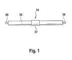
- Figure 1 shows an electric linear generator/motor 54 according to a first special embodiment of the invention. It comprises a pipe 56 with a respective section 58 at each end that has conical inner and outer surfaces in such a way (conversion type) to create high speed fluid jet to impact on the rotor (not shown) within the pipe 56.
- the pipe 64 contains a low pressure fluid or vacuum.
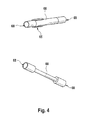
- the electric linear generator/motor 60 shown in figures 2 and 3 is different from the electrical linear generator 45 shown in figure 1 in that the outer sections 62 of the pipe 64 in the stator 65 have different inner and outer surfaces. Said sections 62 could be described as of convergent-divergent type. Condensed liquid (not shown) or low pressure gas collection is collected from an outlet (not shown) of the pipe 64. As can be seen from figure 3 as well as figure 4 , the outer ends of the rotor 66 (shown in the bottom of figure 4 without permanent magnets) have planar or nearly planar outer sides that are accelerated fluid impact surfaces 68.
Landscapes
- Engineering & Computer Science (AREA)
- Power Engineering (AREA)
- Linear Motors (AREA)
- Superconductive Dynamoelectric Machines (AREA)
Abstract
Electric linear generator/motor comprising an elongate stator, an electrical induction coil extending lengthwise within or around the stator, a rotor including or carrying at least one permanent magnet and capable of moving linearly to and fro relative to the stator, and a means for providing connection of the respective ends of the coil with an electrical power storage, electrical power source, electrical device or the like, characterized in that it further comprises a pipe, the stator is designed as a sleeve sitting on the pipe and that the rotor is located in the pipe.
Description
- The present invention relates to an electric linear generator/motor.
- Today, there are many electrical power generation systems that convert mechanical and/or thermal energy into electrical energy. However, most of these systems are very complex and require frequent maintenance, which make them expensive.
- Accordingly, it is the main object of the present invention to provide a less complex and cheaper way of converting energy into electrical energy in particular from moving or expanding fluids or vice versa.
- This object is solved according to the present invention by an electric linear generator comprising an elongate stator, an electrical induction coil extending lengthwise within or around the stator, a rotor including or carrying at least one permanent magnet and capable of moving linearly to and fro relative to the stator, and a means for providing connection of the respective ends of the coil with an electric energy storage, electric energy source, electric device or the like characterized in that it further comprises a pipe, the stator is designed as a sleeve sitting on the pipe and the rotor is located in the pipe.
- In the present application the term "rotor" is used for the movable part of the linear generator. It should therefore be understood that the term "rotor" does not relate to a rotating body but to a body moving linearly to and fro.
- In general, claim 1 relates to an engine or a machine that can be used as a generator or a motor.
- According to a special embodiment of the electric generator/motor the rotor is substantially rod-shaped.
- In particular, both ends of the rod can be expanded.
- Conveniently, the rotor is electromagnetically suspended in the sleeve.
- Preferably, the sleeve includes at least one superconducting magnet or electromagnet preferably with dynamic control or is surrounded by at least one superconducting magnet or electromagnet preferably with dynamic control.
- According to a further special embodiment of said generator, at both ends of the pipe a section is located, the inner surface thereof expanding to the respective pipe end.
- In particular, the sections can be integrally formed with the pipe or the sections can be removably fixed to the pipe.
- Preferably, the inner surface of the sections is conical.
- The invention recognizes that by using a special kind of electric linear generator/motor energy conversion, in particular integrated energy conversion, can be simplified and therefore cheaper in production and/or maintenance.
- A simple impulse free-piston linear generator/motor can be used to construct integrated energy conversion systems in a much lower cost and simpler way than in the prior art.
- In cases where the working fluid is non-corrosive and non-contaminating, for example by way of sections at both ends of the pipe with inner surfaces that expand to the respective pipe end, high speed fluid jets can be generated to move the moving part, i.e. the pipe, of the electrical linear generator. All of these features alone or in combination simplify the design and therefore the cost for the whole system is reduced and the maintenance is simplified.
- Further features and advantages of the invention will become clear from the accompanying claims and the following description, in which preferred embodiments of the invention are illustrated in detail with reference to the schematic drawings, wherein
- Figure 1
- shows a side view of an electric linear generator/motor according to a first preferred embodiment of the invention;
- Figure 2
- shows a side view of an electric linear generator/motor according to a second preferred embodiment of the invention;
- Figure 3
- shows the generator/motor of
figure 2 with part of the pipe being removed; and - Figure 4
- shows parts of the electric linear generator/motor of
figure 2 . -
Figure 1 shows an electric linear generator/motor 54 according to a first special embodiment of the invention. It comprises apipe 56 with arespective section 58 at each end that has conical inner and outer surfaces in such a way (conversion type) to create high speed fluid jet to impact on the rotor (not shown) within thepipe 56. Thepipe 64 contains a low pressure fluid or vacuum. - The electric linear generator/
motor 60 shown infigures 2 and3 is different from the electrical linear generator 45 shown infigure 1 in that theouter sections 62 of thepipe 64 in thestator 65 have different inner and outer surfaces. Saidsections 62 could be described as of convergent-divergent type. Condensed liquid (not shown) or low pressure gas collection is collected from an outlet (not shown) of thepipe 64. As can be seen fromfigure 3 as well asfigure 4 , the outer ends of the rotor 66 (shown in the bottom offigure 4 without permanent magnets) have planar or nearly planar outer sides that are acceleratedfluid impact surfaces 68. - The features in the foregoing description, in the claims and/or in the accompanying drawings may, both and in any combination thereof, be material for realizing the invention in diverse forms thereof.
-
- 54
- electric linear generator/motor
- 56
- pipe
- 57
- stator
- 58
- sections
- 60
- electric linear generator/motor
- 62
- sections
- 64
- pipe
- 65
- stator
- 66
- rotor
- 68
- impact surfaces
Claims (8)
- Electric linear generator/motor (54; 60) comprising- an elongate stator (57; 65),- an electrical induction coil extending lengthwise within or around the stator,- a rotor (66) including or carrying at least one permanent magnet and capable of moving linearly to and fro relative to the stator, and- a means for providing connection of the respective ends of the coil with an electrical energy storage, electrical energy source, electric device or the like, characterized in that
it further comprises a pipe (56; 64), the stator is designed as a sleeve sitting on the pipe and that the rotor is located in the pipe. - Generator/Motor (54; 60) according to claim 1, wherein the rotor (66) is substantially rod-shaped.
- Generator/Motor (54; 60) according to claim 2, wherein both ends of the rod are expanded.
- Generator/Motor (54; 60) according to anyone of claims 1 to 3, wherein the rotor (66) is electromagnetically suspended in the sleeve.
- Generator/Motor according to claim 4, wherein the sleeve includes at least one superconducting magnet or electromagnet preferably with dynamic control or is surrounded by at least one superconducting magnet or electromagnet preferably with dynamic control.
- Generator/Motor (54; 60) according to anyone of the preceding claims, wherein at both ends of the pipe a section (58; 62) is located, the inner surface thereof expanding to the respective pipe end.
- Generator/Motor according to claim 6, wherein the sections are integrally formed with the pipe or wherein the sections are removably fixed to the pipe.
- Generator/Motor (54; 60) according to claim 6 or 7, wherein the inner surface of the sections (58; 62) is conical.
Priority Applications (1)
| Application Number | Priority Date | Filing Date | Title |
|---|---|---|---|
| EP20130186272 EP2854266A1 (en) | 2013-09-27 | 2013-09-27 | Electric linear generator/motor |
Applications Claiming Priority (1)
| Application Number | Priority Date | Filing Date | Title |
|---|---|---|---|
| EP20130186272 EP2854266A1 (en) | 2013-09-27 | 2013-09-27 | Electric linear generator/motor |
Publications (1)
| Publication Number | Publication Date |
|---|---|
| EP2854266A1 true EP2854266A1 (en) | 2015-04-01 |
Family
ID=49231379
Family Applications (1)
| Application Number | Title | Priority Date | Filing Date |
|---|---|---|---|
| EP20130186272 Withdrawn EP2854266A1 (en) | 2013-09-27 | 2013-09-27 | Electric linear generator/motor |
Country Status (1)
| Country | Link |
|---|---|
| EP (1) | EP2854266A1 (en) |
Citations (2)
| Publication number | Priority date | Publication date | Assignee | Title |
|---|---|---|---|---|
| WO2010094059A1 (en) * | 2009-02-22 | 2010-08-26 | Intium Technologies Pty. Ltd. | Techniques for the maximisation of current output from a bi-directionally driven linear induction generator by enhanced magnetic flux focus and coupling within the magnetic force path |
| WO2013006832A1 (en) * | 2011-07-07 | 2013-01-10 | Hanseup Kim | Flexible devices, systems, and methods for harvesting energy |
-
2013
- 2013-09-27 EP EP20130186272 patent/EP2854266A1/en not_active Withdrawn
Patent Citations (2)
| Publication number | Priority date | Publication date | Assignee | Title |
|---|---|---|---|---|
| WO2010094059A1 (en) * | 2009-02-22 | 2010-08-26 | Intium Technologies Pty. Ltd. | Techniques for the maximisation of current output from a bi-directionally driven linear induction generator by enhanced magnetic flux focus and coupling within the magnetic force path |
| WO2013006832A1 (en) * | 2011-07-07 | 2013-01-10 | Hanseup Kim | Flexible devices, systems, and methods for harvesting energy |
Non-Patent Citations (1)
| Title |
|---|
| ANONYMOUS: "Nozzle - Wikipedia, the free encyclopedia", 18 October 2007 (2007-10-18), XP055106163, Retrieved from the Internet <URL:http://web.archive.org/web/20071018091534/http://en.wikipedia.org/wiki/Nozzle> [retrieved on 20140307] * |
Similar Documents
| Publication | Publication Date | Title |
|---|---|---|
| Holm et al. | Design of a magnetic lead screw for wave energy conversion | |
| EP2961042A1 (en) | Permanent magnet machine | |
| KR101872257B1 (en) | Magnet generator | |
| US9647522B2 (en) | Linear induction generator using magnetic repulsion | |
| US10581355B1 (en) | Double-fed induction linear oscillating alternator | |
| CN102832846B (en) | Shaft power generator based on axial flexural vibration of piezoelectric vibrator of cantilever beam | |
| HUE026324T2 (en) | Electric machine having a low-mass design in magnetically active parts | |
| Lu et al. | Performance analysis of linear induction motor for electromagnetic catapult | |
| Gargov et al. | Separated magnet yoke for permanent magnet linear generator for marine wave energy converters | |
| CN110247534A (en) | The integrated multidirectional controlled motion device of electromagnet and permanent magnet combination drive push-and-pull unit | |
| EP2854266A1 (en) | Electric linear generator/motor | |
| CN105656281B (en) | Three-phase magnetic resistance cylindrical linear motor with Exciting Windings for Transverse Differential Protection | |
| CN101217247A (en) | Electric machine (motor and generator) device | |
| US9853529B2 (en) | Linear induction generator using magnetic repulsion | |
| JP5268309B2 (en) | Rod linear actuator | |
| US9537368B2 (en) | Magnetic power generator for hybrid vehicle and/or electric power plant | |
| RU2431758C1 (en) | Electric power generation method and device for its implementation | |
| CN105756867A (en) | Device capable of supplying thrust | |
| EP2854265B1 (en) | Electric linear generators/motors and energy converting systems with the same | |
| Ismagilov et al. | Minimization of energy losses in ultra-high-speed electrical rotating machines | |
| Hamim et al. | Modeling of a tubular permanent magnet linear generator for wave energy conversion using finite element method | |
| Zhou et al. | A novel 6/4 conical bearingless switched reluctance motor | |
| WO2010094059A1 (en) | Techniques for the maximisation of current output from a bi-directionally driven linear induction generator by enhanced magnetic flux focus and coupling within the magnetic force path | |
| MEMON et al. | Finite Element Analysis of Linear Permanent Magnet Generator for Wave Energy Conversion. | |
| Wahyudie et al. | Design of a laboratory scale linear hydraulic wave energy converter |
Legal Events
| Date | Code | Title | Description |
|---|---|---|---|
| PUAI | Public reference made under article 153(3) epc to a published international application that has entered the european phase |
Free format text: ORIGINAL CODE: 0009012 |
|
| 17P | Request for examination filed |
Effective date: 20130927 |
|
| AK | Designated contracting states |
Kind code of ref document: A1 Designated state(s): AL AT BE BG CH CY CZ DE DK EE ES FI FR GB GR HR HU IE IS IT LI LT LU LV MC MK MT NL NO PL PT RO RS SE SI SK SM TR |
|
| AX | Request for extension of the european patent |
Extension state: BA ME |
|
| STAA | Information on the status of an ep patent application or granted ep patent |
Free format text: STATUS: THE APPLICATION IS DEEMED TO BE WITHDRAWN |
|
| 18D | Application deemed to be withdrawn |
Effective date: 20151002 |
|
| P01 | Opt-out of the competence of the unified patent court (upc) registered |
Effective date: 20230411 |