EP2854254A1 - Charging station having battery cell balancing system - Google Patents
Charging station having battery cell balancing system Download PDFInfo
- Publication number
- EP2854254A1 EP2854254A1 EP14181699.1A EP14181699A EP2854254A1 EP 2854254 A1 EP2854254 A1 EP 2854254A1 EP 14181699 A EP14181699 A EP 14181699A EP 2854254 A1 EP2854254 A1 EP 2854254A1
- Authority
- EP
- European Patent Office
- Prior art keywords
- battery cell
- charging
- battery
- balancing
- charge
- Prior art date
- Legal status (The legal status is an assumption and is not a legal conclusion. Google has not performed a legal analysis and makes no representation as to the accuracy of the status listed.)
- Ceased
Links
Images


Classifications
-
- H—ELECTRICITY
- H02—GENERATION; CONVERSION OR DISTRIBUTION OF ELECTRIC POWER
- H02J—CIRCUIT ARRANGEMENTS OR SYSTEMS FOR SUPPLYING OR DISTRIBUTING ELECTRIC POWER; SYSTEMS FOR STORING ELECTRIC ENERGY
- H02J7/00—Circuit arrangements for charging or depolarising batteries or for supplying loads from batteries
- H02J7/0013—Circuit arrangements for charging or depolarising batteries or for supplying loads from batteries acting upon several batteries simultaneously or sequentially
- H02J7/0014—Circuits for equalisation of charge between batteries
-
- B—PERFORMING OPERATIONS; TRANSPORTING
- B60—VEHICLES IN GENERAL
- B60L—PROPULSION OF ELECTRICALLY-PROPELLED VEHICLES; SUPPLYING ELECTRIC POWER FOR AUXILIARY EQUIPMENT OF ELECTRICALLY-PROPELLED VEHICLES; ELECTRODYNAMIC BRAKE SYSTEMS FOR VEHICLES IN GENERAL; MAGNETIC SUSPENSION OR LEVITATION FOR VEHICLES; MONITORING OPERATING VARIABLES OF ELECTRICALLY-PROPELLED VEHICLES; ELECTRIC SAFETY DEVICES FOR ELECTRICALLY-PROPELLED VEHICLES
- B60L53/00—Methods of charging batteries, specially adapted for electric vehicles; Charging stations or on-board charging equipment therefor; Exchange of energy storage elements in electric vehicles
- B60L53/10—Methods of charging batteries, specially adapted for electric vehicles; Charging stations or on-board charging equipment therefor; Exchange of energy storage elements in electric vehicles characterised by the energy transfer between the charging station and the vehicle
- B60L53/14—Conductive energy transfer
- B60L53/16—Connectors, e.g. plugs or sockets, specially adapted for charging electric vehicles
-
- B—PERFORMING OPERATIONS; TRANSPORTING
- B60—VEHICLES IN GENERAL
- B60L—PROPULSION OF ELECTRICALLY-PROPELLED VEHICLES; SUPPLYING ELECTRIC POWER FOR AUXILIARY EQUIPMENT OF ELECTRICALLY-PROPELLED VEHICLES; ELECTRODYNAMIC BRAKE SYSTEMS FOR VEHICLES IN GENERAL; MAGNETIC SUSPENSION OR LEVITATION FOR VEHICLES; MONITORING OPERATING VARIABLES OF ELECTRICALLY-PROPELLED VEHICLES; ELECTRIC SAFETY DEVICES FOR ELECTRICALLY-PROPELLED VEHICLES
- B60L53/00—Methods of charging batteries, specially adapted for electric vehicles; Charging stations or on-board charging equipment therefor; Exchange of energy storage elements in electric vehicles
- B60L53/10—Methods of charging batteries, specially adapted for electric vehicles; Charging stations or on-board charging equipment therefor; Exchange of energy storage elements in electric vehicles characterised by the energy transfer between the charging station and the vehicle
- B60L53/14—Conductive energy transfer
- B60L53/18—Cables specially adapted for charging electric vehicles
-
- B—PERFORMING OPERATIONS; TRANSPORTING
- B60—VEHICLES IN GENERAL
- B60L—PROPULSION OF ELECTRICALLY-PROPELLED VEHICLES; SUPPLYING ELECTRIC POWER FOR AUXILIARY EQUIPMENT OF ELECTRICALLY-PROPELLED VEHICLES; ELECTRODYNAMIC BRAKE SYSTEMS FOR VEHICLES IN GENERAL; MAGNETIC SUSPENSION OR LEVITATION FOR VEHICLES; MONITORING OPERATING VARIABLES OF ELECTRICALLY-PROPELLED VEHICLES; ELECTRIC SAFETY DEVICES FOR ELECTRICALLY-PROPELLED VEHICLES
- B60L53/00—Methods of charging batteries, specially adapted for electric vehicles; Charging stations or on-board charging equipment therefor; Exchange of energy storage elements in electric vehicles
- B60L53/30—Constructional details of charging stations
-
- B—PERFORMING OPERATIONS; TRANSPORTING
- B60—VEHICLES IN GENERAL
- B60L—PROPULSION OF ELECTRICALLY-PROPELLED VEHICLES; SUPPLYING ELECTRIC POWER FOR AUXILIARY EQUIPMENT OF ELECTRICALLY-PROPELLED VEHICLES; ELECTRODYNAMIC BRAKE SYSTEMS FOR VEHICLES IN GENERAL; MAGNETIC SUSPENSION OR LEVITATION FOR VEHICLES; MONITORING OPERATING VARIABLES OF ELECTRICALLY-PROPELLED VEHICLES; ELECTRIC SAFETY DEVICES FOR ELECTRICALLY-PROPELLED VEHICLES
- B60L58/00—Methods or circuit arrangements for monitoring or controlling batteries or fuel cells, specially adapted for electric vehicles
- B60L58/10—Methods or circuit arrangements for monitoring or controlling batteries or fuel cells, specially adapted for electric vehicles for monitoring or controlling batteries
- B60L58/12—Methods or circuit arrangements for monitoring or controlling batteries or fuel cells, specially adapted for electric vehicles for monitoring or controlling batteries responding to state of charge [SoC]
-
- B—PERFORMING OPERATIONS; TRANSPORTING
- B60—VEHICLES IN GENERAL
- B60L—PROPULSION OF ELECTRICALLY-PROPELLED VEHICLES; SUPPLYING ELECTRIC POWER FOR AUXILIARY EQUIPMENT OF ELECTRICALLY-PROPELLED VEHICLES; ELECTRODYNAMIC BRAKE SYSTEMS FOR VEHICLES IN GENERAL; MAGNETIC SUSPENSION OR LEVITATION FOR VEHICLES; MONITORING OPERATING VARIABLES OF ELECTRICALLY-PROPELLED VEHICLES; ELECTRIC SAFETY DEVICES FOR ELECTRICALLY-PROPELLED VEHICLES
- B60L58/00—Methods or circuit arrangements for monitoring or controlling batteries or fuel cells, specially adapted for electric vehicles
- B60L58/10—Methods or circuit arrangements for monitoring or controlling batteries or fuel cells, specially adapted for electric vehicles for monitoring or controlling batteries
- B60L58/18—Methods or circuit arrangements for monitoring or controlling batteries or fuel cells, specially adapted for electric vehicles for monitoring or controlling batteries of two or more battery modules
- B60L58/22—Balancing the charge of battery modules
-
- H—ELECTRICITY
- H02—GENERATION; CONVERSION OR DISTRIBUTION OF ELECTRIC POWER
- H02J—CIRCUIT ARRANGEMENTS OR SYSTEMS FOR SUPPLYING OR DISTRIBUTING ELECTRIC POWER; SYSTEMS FOR STORING ELECTRIC ENERGY
- H02J7/00—Circuit arrangements for charging or depolarising batteries or for supplying loads from batteries
- H02J7/0013—Circuit arrangements for charging or depolarising batteries or for supplying loads from batteries acting upon several batteries simultaneously or sequentially
- H02J7/0014—Circuits for equalisation of charge between batteries
- H02J7/0016—Circuits for equalisation of charge between batteries using shunting, discharge or bypass circuits
-
- H—ELECTRICITY
- H02—GENERATION; CONVERSION OR DISTRIBUTION OF ELECTRIC POWER
- H02J—CIRCUIT ARRANGEMENTS OR SYSTEMS FOR SUPPLYING OR DISTRIBUTING ELECTRIC POWER; SYSTEMS FOR STORING ELECTRIC ENERGY
- H02J7/00—Circuit arrangements for charging or depolarising batteries or for supplying loads from batteries
- H02J7/0013—Circuit arrangements for charging or depolarising batteries or for supplying loads from batteries acting upon several batteries simultaneously or sequentially
- H02J7/0014—Circuits for equalisation of charge between batteries
- H02J7/0018—Circuits for equalisation of charge between batteries using separate charge circuits
-
- B—PERFORMING OPERATIONS; TRANSPORTING
- B60—VEHICLES IN GENERAL
- B60L—PROPULSION OF ELECTRICALLY-PROPELLED VEHICLES; SUPPLYING ELECTRIC POWER FOR AUXILIARY EQUIPMENT OF ELECTRICALLY-PROPELLED VEHICLES; ELECTRODYNAMIC BRAKE SYSTEMS FOR VEHICLES IN GENERAL; MAGNETIC SUSPENSION OR LEVITATION FOR VEHICLES; MONITORING OPERATING VARIABLES OF ELECTRICALLY-PROPELLED VEHICLES; ELECTRIC SAFETY DEVICES FOR ELECTRICALLY-PROPELLED VEHICLES
- B60L2240/00—Control parameters of input or output; Target parameters
- B60L2240/40—Drive Train control parameters
- B60L2240/54—Drive Train control parameters related to batteries
- B60L2240/545—Temperature
-
- B—PERFORMING OPERATIONS; TRANSPORTING
- B60—VEHICLES IN GENERAL
- B60L—PROPULSION OF ELECTRICALLY-PROPELLED VEHICLES; SUPPLYING ELECTRIC POWER FOR AUXILIARY EQUIPMENT OF ELECTRICALLY-PROPELLED VEHICLES; ELECTRODYNAMIC BRAKE SYSTEMS FOR VEHICLES IN GENERAL; MAGNETIC SUSPENSION OR LEVITATION FOR VEHICLES; MONITORING OPERATING VARIABLES OF ELECTRICALLY-PROPELLED VEHICLES; ELECTRIC SAFETY DEVICES FOR ELECTRICALLY-PROPELLED VEHICLES
- B60L2240/00—Control parameters of input or output; Target parameters
- B60L2240/40—Drive Train control parameters
- B60L2240/54—Drive Train control parameters related to batteries
- B60L2240/547—Voltage
-
- B—PERFORMING OPERATIONS; TRANSPORTING
- B60—VEHICLES IN GENERAL
- B60L—PROPULSION OF ELECTRICALLY-PROPELLED VEHICLES; SUPPLYING ELECTRIC POWER FOR AUXILIARY EQUIPMENT OF ELECTRICALLY-PROPELLED VEHICLES; ELECTRODYNAMIC BRAKE SYSTEMS FOR VEHICLES IN GENERAL; MAGNETIC SUSPENSION OR LEVITATION FOR VEHICLES; MONITORING OPERATING VARIABLES OF ELECTRICALLY-PROPELLED VEHICLES; ELECTRIC SAFETY DEVICES FOR ELECTRICALLY-PROPELLED VEHICLES
- B60L2240/00—Control parameters of input or output; Target parameters
- B60L2240/40—Drive Train control parameters
- B60L2240/54—Drive Train control parameters related to batteries
- B60L2240/549—Current
-
- Y—GENERAL TAGGING OF NEW TECHNOLOGICAL DEVELOPMENTS; GENERAL TAGGING OF CROSS-SECTIONAL TECHNOLOGIES SPANNING OVER SEVERAL SECTIONS OF THE IPC; TECHNICAL SUBJECTS COVERED BY FORMER USPC CROSS-REFERENCE ART COLLECTIONS [XRACs] AND DIGESTS
- Y02—TECHNOLOGIES OR APPLICATIONS FOR MITIGATION OR ADAPTATION AGAINST CLIMATE CHANGE
- Y02T—CLIMATE CHANGE MITIGATION TECHNOLOGIES RELATED TO TRANSPORTATION
- Y02T10/00—Road transport of goods or passengers
- Y02T10/60—Other road transportation technologies with climate change mitigation effect
- Y02T10/70—Energy storage systems for electromobility, e.g. batteries
-
- Y—GENERAL TAGGING OF NEW TECHNOLOGICAL DEVELOPMENTS; GENERAL TAGGING OF CROSS-SECTIONAL TECHNOLOGIES SPANNING OVER SEVERAL SECTIONS OF THE IPC; TECHNICAL SUBJECTS COVERED BY FORMER USPC CROSS-REFERENCE ART COLLECTIONS [XRACs] AND DIGESTS
- Y02—TECHNOLOGIES OR APPLICATIONS FOR MITIGATION OR ADAPTATION AGAINST CLIMATE CHANGE
- Y02T—CLIMATE CHANGE MITIGATION TECHNOLOGIES RELATED TO TRANSPORTATION
- Y02T10/00—Road transport of goods or passengers
- Y02T10/60—Other road transportation technologies with climate change mitigation effect
- Y02T10/7072—Electromobility specific charging systems or methods for batteries, ultracapacitors, supercapacitors or double-layer capacitors
-
- Y—GENERAL TAGGING OF NEW TECHNOLOGICAL DEVELOPMENTS; GENERAL TAGGING OF CROSS-SECTIONAL TECHNOLOGIES SPANNING OVER SEVERAL SECTIONS OF THE IPC; TECHNICAL SUBJECTS COVERED BY FORMER USPC CROSS-REFERENCE ART COLLECTIONS [XRACs] AND DIGESTS
- Y02—TECHNOLOGIES OR APPLICATIONS FOR MITIGATION OR ADAPTATION AGAINST CLIMATE CHANGE
- Y02T—CLIMATE CHANGE MITIGATION TECHNOLOGIES RELATED TO TRANSPORTATION
- Y02T90/00—Enabling technologies or technologies with a potential or indirect contribution to GHG emissions mitigation
- Y02T90/10—Technologies relating to charging of electric vehicles
- Y02T90/12—Electric charging stations
-
- Y—GENERAL TAGGING OF NEW TECHNOLOGICAL DEVELOPMENTS; GENERAL TAGGING OF CROSS-SECTIONAL TECHNOLOGIES SPANNING OVER SEVERAL SECTIONS OF THE IPC; TECHNICAL SUBJECTS COVERED BY FORMER USPC CROSS-REFERENCE ART COLLECTIONS [XRACs] AND DIGESTS
- Y02—TECHNOLOGIES OR APPLICATIONS FOR MITIGATION OR ADAPTATION AGAINST CLIMATE CHANGE
- Y02T—CLIMATE CHANGE MITIGATION TECHNOLOGIES RELATED TO TRANSPORTATION
- Y02T90/00—Enabling technologies or technologies with a potential or indirect contribution to GHG emissions mitigation
- Y02T90/10—Technologies relating to charging of electric vehicles
- Y02T90/14—Plug-in electric vehicles
Definitions
- the present invention relates to a charging station. More particularly, the present invention relates to a charging station which has battery cell balancing systems. Thus, each battery pack charged by the charging station doesn't need to comprise a battery cell balancing system to extend life of the battery. Size and cost of the battery can be reduced, too.
- Battery imbalance that means mismatch of the state of charge of battery cells in a battery pack
- the imbalance may reduce the total capacity of the battery pack, and may damage the battery pack, too.
- the imbalance of the battery from charging to discharging state can not be traced. If it is not closely monitored, the battery may leads to overcharge or over-discharge, which will permanently damage the battery.
- the above issue becomes more significant, especially for lithium batteries.
- lithium iron phosphate batteries are developed to enhance voltage and current.
- it is also easily cause "imbalance" to shorten caused discharge time of the battery pack (i.e., the lifetime time is shortened), and accelerate the aging of the battery pack.
- BMS Battery Management System
- the BMS uses a balance loop to achieve the above goal. Most of the balance loops are used during battery pack charging. It is scarcely used in battery pack discharge.
- the balance loop can be divided into two type, the active type and passive type.
- the active type balance loop has advantage of high efficiency, but it also has drawback of high cost and big size.
- Passive type balance loop has advantages of cheap cost. However, the disadvantage is low efficiency which will generate heat. Balance effect is limited.
- the active type is highly efficient, considering the price, most of the battery packs are chosen to built-in passive type balance loop.
- US Patent Application No. 20120105001 discloses a battery management system.
- the battery management system includes several subsystem blocks, an energy storage master unit 100, and battery pack systems 104.
- the energy storage master may interface with the vehicle master controller (ZR32-A) 101 with a pass through from the energy storage master 100 by way of CAN or other communication method to an external charger 102.
- the vehicle master controller 101 may interface with the external charger 102 either directly or through a charging station interface.
- the energy storage system may include several strings of batteries 103 in an electric vehicle.
- each pack 104 there may be packs 104, and each pack is comprised of several battery modules.
- the battery packs 104 may communicate to the energy storage master 100 by way of a second CAN bus.
- Two battery packs 104 may make up a string 103.
- the packs may be controlled by a pack master, which may communicate with the energy storage master 100 using a single CAN bus for the entire system.
- Each pack master may communicate with its local module unit using an serial peripheral interface (SPI) bus.
- SPI serial peripheral interface
- the local module unit and pack master communications may be isolated.
- the battery packs containing 10 prismatic battery cells each. There are 2 packs per string, and a variable number of strings per vehicle (typically 3 to 4).
- the battery pack comes with the battery cell balancing system would still be bulky. However, it provides people a way to reduce the size: taking the battery cell balancing system out of the battery pack. If one or more sets of battery cell balancing systems can be setup out of battery packs, the cost of battery cell balancing system can be saved. In addition, the battery pack size can be smaller. More economic and convenient, a charging station can combine the battery cell balancing system to provide power to battery pack while monitors state of each battery cell or pack. It is the point the inventor created the present invention.
- a charging station having a battery cell balancing system includes: a plurality of balancing charging units, each has: a detecting element for detecting a state of charge of a battery cell; and a charging element for processing charging to the battery cell; a power unit for providing electric power; and a charging control unit, linked to the balancing charging units, and the power unit, for controlling the electric power from the power unit to the charging element to charge the battery cell.
- the battery cell is linked in serial or parallel with other battery cells in a battery pack, and the charging control unit stops the power unit to charge the battery cell when the state of charge of the battery cell detected by the detecting element is full or exceeds a predetermined value.
- the state of charge can be determined by temperature, voltage or current of the battery pack.
- the state of charge is in the form of percentage indicating the amount of energy left in a battery cell.
- the balancing charging unit is an active type or a passive type.
- the balancing charging unit can transfer electric power from a higher charged battery cell to a lower charged battery cell when the balancing charging unit is the active type.
- the charging station further comprises a resistor to absorb or consume electric power from a higher charged battery cell when the balancing charging unit is the passive type.
- the charging station further comprises a memory unit, linked to the charging control unit, for providing historical data of the battery cell so that the charging control unit can know when the battery cell is fully charged or exceeds a predetermined value.
- the historical data is temperature, voltage or current of the battery cell when the battery cell was measured at any time.
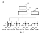
- FIG. 2 illustrates a schematic diagram of a first embodiment of the present invention.
- FIG. 3 illustrates a battery used according to the present invention.
- a charging station 20 has a battery cell balancing system. It comprises a number of balancing charging units 2021, 2022, 2023 and 2024, a charging control unit 201 and a power unit 203.
- Each balancing charging units 2021, 2022, 2023 and 2024 has a detecting element 2021a, 2022a, 2023a and 2024a, respectively.
- Each balancing charging units 2021, 2022, 2023 and 2024 also has a charging element 2021b, 2022b, 2023b and 2024b, respectively.
- the detecting elements 2021a, 2022a, 2023a and 2024a can detecting a state of charge of a battery cell 3021, 3022, 3023 and 3024.
- the charging elements 2021b, 2022b, 2023b and 2024b are used for processing charging to the battery cell 3021, 3022, 3023 and 3024, respectively.
- the power unit 203 can provide electric power. In practice and also in this embodiment, the power unit 203 is a DC generator and provides DC power.
- the charging control unit 201 are linked to the balancing charging units 2021, 2022, 2023 and 2024, and the power unit 203. It can control the electric power from the power unit 203 to the charging elements 2021b, 2022b, 2023b and 2024b to charge the battery cells 3021, 3022, 3023 and 3024.
- the charging station 20 has four balancing charging units for charging control of the battery cells 3021, 3022, 3023 and 3024.
- the number of balancing charging units is not limited to four. In practice, the number should be more than the battery cells in a battery pack.
- the battery cell is linked in serial or parallel with other batteries in a battery pack 30 (Please refer to Fig. 3 ).
- two battery cells 3021 and 3022 (or 3023 and 3024) are linked in serial; two serially linked battery strings are linked in parallel.
- the battery pack 30 has four battery cells 3021, 3022, 3023 and 3024 and each of the battery cells 3021, 3022, 3023 and 3024 are controlled by the balancing charging units 2021, 2022, 2023 and 2024.
- the charging control unit 201 stops the power unit 203 to charge the battery cells 3021, 3022, 3023 and 3024 when the state of charge of the battery cell 3021, 3022, 3023 or 3024 detected by the detecting element 2021a, 2022a, 2023a or 2024a is full or exceeds a predetermined value.
- state of charge is the amount of energy left in a battery cell and is the equivalent of a fuel gauge for the battery pack 30 in a battery electric vehicle.
- the state of charge can be determined by temperature, voltage or current of the battery pack 30. Namely, by means of above, people can know how full the battery cell 302 can be.
- the first embodiment illustrates how an active type balancing charging unit is applied in the present invention.
- the active type balancing charging unit is designed to discharge a battery cell when the voltage difference has reached a certain extent after a period of charge. It is not necessary for each battery cell 3021, 3022, 3023 or 3024 to be 100% full.
- a defined state of charge of the battery cells 3021, 3022, 3023 and 3024 can be used to assume the battery cell 3021, 3022, 3023 or 3024 is fully charged or exceeds a predetermined value.
- the balancing charging unit 2021, 2022, 2023 or 2024 can transfer electric power from a higher charged battery cell to a lower charged battery cell.
- the charging control unit 201 can stop charging the battery cell 3022 while keeps charging other battery cells 3021, 3023 and 3024.
- the balancing charging units are built in a battery pack so that the battery pack can control charge of each cell to prevent the battery pack from aging due to imbalance of battery cells.
- the present invention provides the design to take all balancing charging units out of the battery pack and design them into a charging station.
- the present invention also requests the battery pack 30 to have some specified designs: contacts (for example 3021a and 3021b) of the battery cell (for example 3021) on a housing 300 of the battery pack 30 should meet the specification of the detecting element 2021a and the charging element 2021b, respectively.
- the charging station 20 can further comprises a memory unit 204. It is linked to the charging control unit 201.
- the memory unit 204 can provide historical data of the battery cells 3021, 3022, 3023 and 3024 so that the charging control unit 201 can know when the battery cell 3021, 3022, 3023 or 3024 is fully charged or exceeds a predetermined value.
- the historical data is temperature, voltage or current of the battery cells 3021, 3022, 3023 and 3024 when the battery cells 3021, 3022, 3023 and 3024 were measured at any time.
- FIG. 4 A second embodiment is illustrated. In order not to spend time on defining the same elements in the first embodiment, for then element having the same serial number in both embodiments has the same function. From Fig. 5, it is obvious that four resistor 2021c, 2022c, 2023c and 2024c are built and linked to the balancing charging units 2021, 2022, 2023 and 2024, respectively.
- the first embodiment illustrates how an active type balancing charging unit is applied in the present invention.
- the second embodiment illustrates how a passive type balancing charging unit is applied in the present invention.
- the passive type balancing charging unit usually absorbs or consumes electric power from a higher charged battery cell by the resistor 2021c, 2022c, 2023c or 2024c.
- the resistors 2021c, 2022c, 2023c and 2024c can be designed to only one. It can also be other forms as long as excess electric power can be taken away and not affects the efficiency of each battery cell 3021, 3022, 3023 or 3024.
Abstract
Description
- The present invention relates to a charging station. More particularly, the present invention relates to a charging station which has battery cell balancing systems. Thus, each battery pack charged by the charging station doesn't need to comprise a battery cell balancing system to extend life of the battery. Size and cost of the battery can be reduced, too.
- With the battery becoming increasingly popular as a power source, there has been an equally strong demand, maximizing battery life. Battery imbalance (that means mismatch of the state of charge of battery cells in a battery pack) in large lithium-ion battery pack is a problem. This problem is caused by differences in manufacturing processes, working conditions and battery aging. The imbalance may reduce the total capacity of the battery pack, and may damage the battery pack, too. The imbalance of the battery from charging to discharging state can not be traced. If it is not closely monitored, the battery may leads to overcharge or over-discharge, which will permanently damage the battery. For car-used battery, the above issue becomes more significant, especially for lithium batteries.
- In general, the voltage of each lithium battery is not high and the current is not strong enough. Therefore, lithium iron phosphate batteries are developed to enhance voltage and current. However, when such batteries are connected in series and parallel, it is also easily cause "imbalance" to shorten caused discharge time of the battery pack (i.e., the lifetime time is shortened), and accelerate the aging of the battery pack.
- BMS (Battery Management System) is a protection mechanism. It is used for monitoring the whole battery pack. When the battery pack is detected to have some battery cells which are imbalance, it will turn off the entire battery pack system and the battery pack no longer supply power. The BMS uses a balance loop to achieve the above goal. Most of the balance loops are used during battery pack charging. It is scarcely used in battery pack discharge. The balance loop can be divided into two type, the active type and passive type. The active type balance loop has advantage of high efficiency, but it also has drawback of high cost and big size. Passive type balance loop has advantages of cheap cost. However, the disadvantage is low efficiency which will generate heat. Balance effect is limited. Although the active type is highly efficient, considering the price, most of the battery packs are chosen to built-in passive type balance loop.
- For an electron vehicle, it is not desired that the battery pack which is used is too large. Therefore, the BMS of the battery should be designed properly. A prior art can be a good example. Please refer to
Fig. 1 .US Patent Application No. 20120105001 discloses a battery management system. The battery management system includes several subsystem blocks, an energy storage master unit 100, andbattery pack systems 104. The energy storage master may interface with the vehicle master controller (ZR32-A) 101 with a pass through from the energy storage master 100 by way of CAN or other communication method to anexternal charger 102. Thevehicle master controller 101 may interface with theexternal charger 102 either directly or through a charging station interface. The energy storage system may include several strings ofbatteries 103 in an electric vehicle. Within each of thesestrings 103, there may bepacks 104, and each pack is comprised of several battery modules. Thebattery packs 104 may communicate to the energy storage master 100 by way of a second CAN bus. Twobattery packs 104 may make up astring 103. The packs may be controlled by a pack master, which may communicate with the energy storage master 100 using a single CAN bus for the entire system. Each pack master may communicate with its local module unit using an serial peripheral interface (SPI) bus. The local module unit and pack master communications may be isolated. The battery packs containing 10 prismatic battery cells each. There are 2 packs per string, and a variable number of strings per vehicle (typically 3 to 4). - According to the invention, the battery pack comes with the battery cell balancing system would still be bulky. However, it provides people a way to reduce the size: taking the battery cell balancing system out of the battery pack. If one or more sets of battery cell balancing systems can be setup out of battery packs, the cost of battery cell balancing system can be saved. In addition, the battery pack size can be smaller. More economic and convenient, a charging station can combine the battery cell balancing system to provide power to battery pack while monitors state of each battery cell or pack. It is the point the inventor created the present invention.
- This paragraph extracts and compiles some features of the present invention; other features will be disclosed in the follow-up paragraphs. It is intended to cover various modifications and similar arrangements included within the spirit and scope of the appended claims.
- In accordance with an aspect of the present invention, a charging station having a battery cell balancing system includes: a plurality of balancing charging units, each has: a detecting element for detecting a state of charge of a battery cell; and a charging element for processing charging to the battery cell; a power unit for providing electric power; and a charging control unit, linked to the balancing charging units, and the power unit, for controlling the electric power from the power unit to the charging element to charge the battery cell. The battery cell is linked in serial or parallel with other battery cells in a battery pack, and the charging control unit stops the power unit to charge the battery cell when the state of charge of the battery cell detected by the detecting element is full or exceeds a predetermined value.
- Preferably, the state of charge can be determined by temperature, voltage or current of the battery pack.
- Preferably, the state of charge is in the form of percentage indicating the amount of energy left in a battery cell.
- Preferably, the balancing charging unit is an active type or a passive type.
- Preferably, the balancing charging unit can transfer electric power from a higher charged battery cell to a lower charged battery cell when the balancing charging unit is the active type.
- Preferably, the charging station further comprises a resistor to absorb or consume electric power from a higher charged battery cell when the balancing charging unit is the passive type.
- Preferably, the charging station further comprises a memory unit, linked to the charging control unit, for providing historical data of the battery cell so that the charging control unit can know when the battery cell is fully charged or exceeds a predetermined value.
- Preferably, the historical data is temperature, voltage or current of the battery cell when the battery cell was measured at any time.
-
-
Fig. 1 shows a prior art of battery cell balancing system. -
Fig. 2 illustrates a schematic diagram of a first embodiment of the present invention. -
Fig. 3 illustrates a battery used according to the present invention. -
Fig. 4 illustrates a schematic diagram of a second embodiment of the present invention. - The present invention will now be described more specifically with reference to the following embodiments.
- Please refer to
Fig. 2 andFig. 3 .Fig. 2 illustrates a schematic diagram of a first embodiment of the present invention.Fig. 3 illustrates a battery used according to the present invention. A chargingstation 20 has a battery cell balancing system. It comprises a number ofbalancing charging units control unit 201 and apower unit 203. Eachbalancing charging units element balancing charging units element - The detecting
elements battery cell elements battery cell power unit 203 can provide electric power. In practice and also in this embodiment, thepower unit 203 is a DC generator and provides DC power. The chargingcontrol unit 201 are linked to thebalancing charging units power unit 203. It can control the electric power from thepower unit 203 to thecharging elements battery cells - From
Fig. 2 , it is obvious that the chargingstation 20 has four balancing charging units for charging control of thebattery cells Fig. 3 ). In this embodiment, twobattery cells 3021 and 3022 (or 3023 and 3024) are linked in serial; two serially linked battery strings are linked in parallel. Thebattery pack 30 has fourbattery cells battery cells balancing charging units - The charging
control unit 201 stops thepower unit 203 to charge thebattery cells battery cell element battery pack 30 in a battery electric vehicle. The units of state of charge are percentage points (0% = empty; 100% = full). The state of charge can be determined by temperature, voltage or current of thebattery pack 30. Namely, by means of above, people can know how full the battery cell 302 can be. - There are two types of balancing charging units, active type or passive type. The first embodiment illustrates how an active type balancing charging unit is applied in the present invention. The active type balancing charging unit is designed to discharge a battery cell when the voltage difference has reached a certain extent after a period of charge. It is not necessary for each
battery cell battery cells battery cell balancing charging unit battery cell 3022 is 99% full, excess power charged will be transferred to the 90%full battery cell 3024. Meanwhile, the other twobattery cells control unit 201 can stop charging thebattery cell 3022 while keeps chargingother battery cells - Conventionally, the balancing charging units are built in a battery pack so that the battery pack can control charge of each cell to prevent the battery pack from aging due to imbalance of battery cells. However, it will make the battery cell bulgy and more expensive. The present invention provides the design to take all balancing charging units out of the battery pack and design them into a charging station. Of course, the present invention also requests the
battery pack 30 to have some specified designs: contacts (for example 3021a and 3021b) of the battery cell (for example 3021) on ahousing 300 of thebattery pack 30 should meet the specification of the detectingelement 2021a and the chargingelement 2021b, respectively. - Ideally, the charging
station 20 can further comprises amemory unit 204. It is linked to the chargingcontrol unit 201. Thememory unit 204 can provide historical data of thebattery cells control unit 201 can know when thebattery cell battery cells battery cells - Please refer to
Fig. 4 . A second embodiment is illustrated. In order not to spend time on defining the same elements in the first embodiment, for then element having the same serial number in both embodiments has the same function. From Fig. 5, it is obvious that fourresistor balancing charging units - As mentioned above, the first embodiment illustrates how an active type balancing charging unit is applied in the present invention. The second embodiment illustrates how a passive type balancing charging unit is applied in the present invention. The passive type balancing charging unit usually absorbs or consumes electric power from a higher charged battery cell by the
resistor resistors battery cell - While the invention has been described in terms of what is presently considered to be the most practical and preferred embodiment, it is to be understood that the invention needs not be limited to the disclosed embodiment. On the contrary, it is intended to cover various modifications and similar arrangements included within the spirit and scope of the appended claims, which are to be accorded with the broadest interpretation so as to encompass all such modifications and similar structures.
Claims (8)
- A charging station having a battery cell balancing system, comprising:a plurality of balancing charging units, each has:a detecting element for detecting a state of charge of a battery cell; anda charging element for processing charging to the battery cell;a power unit for providing electric power; anda charging control unit, linked to the balancing charging units, and the power unit, for controlling the electric power from the power unit to the charging element to charge the battery cell;wherein the battery cell is linked in serial or parallel with other battery cells in a battery pack, and the charging control unit stops the power unit to charge the battery cell when the state of charge of the battery cell detected by the detecting element is full or exceeds a predetermined value.
- The charging station to claim 1, wherein the state of charge can be determined by temperature, voltage or current of the battery pack.
- The charging station to claim 1, wherein the state of charge is in the form of percentage indicating the amount of energy left in a battery cell.
- The charging station to claim 1, wherein the balancing charging unit is an active type or a passive type.
- The charging station to claim 4, wherein the balancing charging unit can transfer electric power from a higher charged battery cell to a lower charged battery cell when the balancing charging unit is the active type.
- The charging station to claim 4, further comprising a resistor to absorb or consume electric power from a higher charged battery cell when the balancing charging unit is the passive type.
- The charging station to claim 1, further comprising a memory unit, linked to the charging control unit, for providing historical data of the battery cell so that the charging control unit can know when the battery cell is fully charged or exceeds a predetermined value.
- The charging station to claim 7, wherein the historical data is temperature, voltage or current of the battery cell when the battery cell was measured at any time.
Applications Claiming Priority (1)
| Application Number | Priority Date | Filing Date | Title |
|---|---|---|---|
| US14/029,949 US9276415B2 (en) | 2013-09-18 | 2013-09-18 | Charging station having battery cell balancing system |
Publications (1)
| Publication Number | Publication Date |
|---|---|
| EP2854254A1 true EP2854254A1 (en) | 2015-04-01 |
Family
ID=51359310
Family Applications (1)
| Application Number | Title | Priority Date | Filing Date |
|---|---|---|---|
| EP14181699.1A Ceased EP2854254A1 (en) | 2013-09-18 | 2014-08-20 | Charging station having battery cell balancing system |
Country Status (4)
| Country | Link |
|---|---|
| US (1) | US9276415B2 (en) |
| EP (1) | EP2854254A1 (en) |
| JP (1) | JP6612022B2 (en) |
| CN (1) | CN104467064A (en) |
Cited By (3)
| Publication number | Priority date | Publication date | Assignee | Title |
|---|---|---|---|---|
| EP3309921A4 (en) * | 2015-06-09 | 2019-01-16 | Kabushiki Kaisha Toshiba | Charging system |
| US10910847B2 (en) | 2017-12-21 | 2021-02-02 | Eric Paul Grasshoff | Active cell balancing in batteries using switch mode dividers |
| US11876394B2 (en) | 2017-12-21 | 2024-01-16 | Eric Paul Grasshoff | Active cell balancing in batteries using switch mode dividers |
Families Citing this family (2)
| Publication number | Priority date | Publication date | Assignee | Title |
|---|---|---|---|---|
| EP3970258A4 (en) | 2019-05-16 | 2023-01-25 | Troes Corporation | Method and system for dual equilibrium tm battery and battery pack performance management |
| US11569668B2 (en) * | 2020-07-14 | 2023-01-31 | Igrenenergi, Inc. | System and method for dynamic balancing power in a battery pack |
Citations (4)
| Publication number | Priority date | Publication date | Assignee | Title |
|---|---|---|---|---|
| US20100253287A1 (en) * | 2008-05-28 | 2010-10-07 | Kim Ju-Young | Apparatus for balancing of battery pack having function of prevention of over-discharge |
| US20110074355A1 (en) * | 2010-11-04 | 2011-03-31 | Elite Power Solutions, LLC | Battery unit balancing system |
| DE102010017439A1 (en) * | 2010-06-17 | 2011-12-22 | Bmz Batterien-Montage-Zentrum Gmbh | Energy balancing circuit configuration for, e.g. traction accumulator of vehicle, has chargers to perform charging process of cells of energy storage unit using balancing currents, with smaller load |
| US20120105001A1 (en) | 2010-09-02 | 2012-05-03 | Proterra Inc. | Systems and methods for battery management |
Family Cites Families (15)
| Publication number | Priority date | Publication date | Assignee | Title |
|---|---|---|---|---|
| JP2001339865A (en) * | 2000-05-26 | 2001-12-07 | Hitachi Ltd | Cell voltage equalization apparatus, method therefor, hybrid car and manufacturing method of battery assembly |
| CN101312293B (en) * | 2007-05-22 | 2011-02-16 | 深圳市金一泰实业有限公司 | Power lithium battery intelligent management system |
| US8049460B2 (en) * | 2007-07-18 | 2011-11-01 | Tesla Motors, Inc. | Voltage dividing vehicle heater system and method |
| CN101425694A (en) * | 2008-12-10 | 2009-05-06 | 吕成学 | Equalized charging apparatus used for series batteries |
| US8232768B2 (en) | 2009-01-23 | 2012-07-31 | O2Micro, Inc. | System and method for balancing battery cells |
| WO2010093186A2 (en) | 2009-02-15 | 2010-08-19 | Powertron Engineering Co.,Ltd | Apparatus for charging battery cells in balance and control method thereof |
| JP5593849B2 (en) * | 2009-06-12 | 2014-09-24 | 日産自動車株式会社 | Battery monitoring device |
| US8917061B2 (en) | 2009-09-18 | 2014-12-23 | Schneider Electric It Corporation | System and method for battery cell balancing |
| CN202127255U (en) * | 2011-01-24 | 2012-01-25 | 启明信息技术股份有限公司 | Power battery full-balance controller for electric automobile |
| WO2012169315A1 (en) * | 2011-06-09 | 2012-12-13 | 株式会社豊田自動織機 | Secondary battery charging device |
| JP2013005527A (en) * | 2011-06-14 | 2013-01-07 | Sumitomo Electric Ind Ltd | Non-contact charging system and non-contact charging method |
| CN102255358A (en) * | 2011-07-12 | 2011-11-23 | 快特电波科技(苏州)有限公司 | External equalizing device of series-wound lithium ion battery pack |
| US9555715B2 (en) * | 2011-12-08 | 2017-01-31 | Institute For Energy Application Technologies Co., Ltd. | Rapid charging power supply system |
| WO2013128635A1 (en) * | 2012-03-02 | 2013-09-06 | 株式会社 日立製作所 | Storage battery analysis system, storage battery analysis method, and storage battery analysis program |
| CN203135493U (en) * | 2013-02-16 | 2013-08-14 | 河南速达电动汽车科技有限公司 | Quick charger for electric automobile |
-
2013
- 2013-09-18 US US14/029,949 patent/US9276415B2/en active Active
-
2014
- 2014-08-20 CN CN201410411459.0A patent/CN104467064A/en active Pending
- 2014-08-20 EP EP14181699.1A patent/EP2854254A1/en not_active Ceased
- 2014-09-05 JP JP2014181299A patent/JP6612022B2/en active Active
Patent Citations (4)
| Publication number | Priority date | Publication date | Assignee | Title |
|---|---|---|---|---|
| US20100253287A1 (en) * | 2008-05-28 | 2010-10-07 | Kim Ju-Young | Apparatus for balancing of battery pack having function of prevention of over-discharge |
| DE102010017439A1 (en) * | 2010-06-17 | 2011-12-22 | Bmz Batterien-Montage-Zentrum Gmbh | Energy balancing circuit configuration for, e.g. traction accumulator of vehicle, has chargers to perform charging process of cells of energy storage unit using balancing currents, with smaller load |
| US20120105001A1 (en) | 2010-09-02 | 2012-05-03 | Proterra Inc. | Systems and methods for battery management |
| US20110074355A1 (en) * | 2010-11-04 | 2011-03-31 | Elite Power Solutions, LLC | Battery unit balancing system |
Cited By (3)
| Publication number | Priority date | Publication date | Assignee | Title |
|---|---|---|---|---|
| EP3309921A4 (en) * | 2015-06-09 | 2019-01-16 | Kabushiki Kaisha Toshiba | Charging system |
| US10910847B2 (en) | 2017-12-21 | 2021-02-02 | Eric Paul Grasshoff | Active cell balancing in batteries using switch mode dividers |
| US11876394B2 (en) | 2017-12-21 | 2024-01-16 | Eric Paul Grasshoff | Active cell balancing in batteries using switch mode dividers |
Also Published As
| Publication number | Publication date |
|---|---|
| JP6612022B2 (en) | 2019-11-27 |
| US20150077039A1 (en) | 2015-03-19 |
| US9276415B2 (en) | 2016-03-01 |
| CN104467064A (en) | 2015-03-25 |
| JP2015061510A (en) | 2015-03-30 |
Similar Documents
| Publication | Publication Date | Title |
|---|---|---|
| US11855250B2 (en) | Systems and methods for series battery charging | |
| WO2021243550A1 (en) | Large-format battery management system | |
| EP3054554B1 (en) | Battery pack and method of controlling the same | |
| CN102009595A (en) | Device and method for managing energy of lithium batteries of electric vehicles | |
| EP2854254A1 (en) | Charging station having battery cell balancing system | |
| CN111009948A (en) | Lithium battery protection board capable of actively adjusting charging and discharging current and current adjusting mode thereof | |
| US11831716B2 (en) | System and method for communication between BMSs | |
| WO2017000275A1 (en) | Power storage battery power supply system | |
| CN107294163B (en) | Storage battery state inspection method and device with storage battery monomer balancing function | |
| CN101599560A (en) | The charging device of lithium secondary battery and charging method | |
| CN203387282U (en) | Box-level battery management system | |
| CN202435066U (en) | Lithium-ion battery pack management system with two-way current limiting function | |
| TWI538345B (en) | Charging station having battery cell balancing system | |
| CN108512262B (en) | Energy storage battery management system and equalization method and device thereof | |
| CN204596884U (en) | Acid-base resonance battery device with damping function | |
| CN217692735U (en) | Portable charge-discharge instrument based on battery management system | |
| KR102598680B1 (en) | Uninterruptible power supply using recycled lithium ion battery | |
| CN106410893A (en) | Automatic charging control method for lithium battery spacecraft | |
| KR101809825B1 (en) | Acid/alkaline hybrid resonance battery device with damping function | |
| CN116707096A (en) | Lithium battery charging method and charging device thereof | |
| CN110739761A (en) | dry battery storage and discharge system utilizing solar energy | |
| CN109818406A (en) | A kind of new type solar energy lighting system | |
| CN106159306A (en) | Acid-base resonance battery device with damping function | |
| CN102867984A (en) | Lithium ion battery system, lithium ion battery direct current output control method and device | |
| KR20120092207A (en) | Battery management system that charges battery pack with solar energy without using photovoltaic inverter |
Legal Events
| Date | Code | Title | Description |
|---|---|---|---|
| PUAI | Public reference made under article 153(3) epc to a published international application that has entered the european phase |
Free format text: ORIGINAL CODE: 0009012 |
|
| 17P | Request for examination filed |
Effective date: 20140820 |
|
| AK | Designated contracting states |
Kind code of ref document: A1 Designated state(s): AL AT BE BG CH CY CZ DE DK EE ES FI FR GB GR HR HU IE IS IT LI LT LU LV MC MK MT NL NO PL PT RO RS SE SI SK SM TR |
|
| AX | Request for extension of the european patent |
Extension state: BA ME |
|
| R17P | Request for examination filed (corrected) |
Effective date: 20150804 |
|
| RBV | Designated contracting states (corrected) |
Designated state(s): AL AT BE BG CH CY CZ DE DK EE ES FI FR GB GR HR HU IE IS IT LI LT LU LV MC MK MT NL NO PL PT RO RS SE SI SK SM TR |
|
| 17Q | First examination report despatched |
Effective date: 20160211 |
|
| STAA | Information on the status of an ep patent application or granted ep patent |
Free format text: STATUS: EXAMINATION IS IN PROGRESS |
|
| STAA | Information on the status of an ep patent application or granted ep patent |
Free format text: STATUS: EXAMINATION IS IN PROGRESS |
|
| APBK | Appeal reference recorded |
Free format text: ORIGINAL CODE: EPIDOSNREFNE |
|
| APBN | Date of receipt of notice of appeal recorded |
Free format text: ORIGINAL CODE: EPIDOSNNOA2E |
|
| APBR | Date of receipt of statement of grounds of appeal recorded |
Free format text: ORIGINAL CODE: EPIDOSNNOA3E |
|
| APAF | Appeal reference modified |
Free format text: ORIGINAL CODE: EPIDOSCREFNE |
|
| APBT | Appeal procedure closed |
Free format text: ORIGINAL CODE: EPIDOSNNOA9E |
|
| STAA | Information on the status of an ep patent application or granted ep patent |
Free format text: STATUS: THE APPLICATION HAS BEEN REFUSED |
|
| 18R | Application refused |
Effective date: 20211206 |