EP2854244A2 - Cable stripper - Google Patents
Cable stripper Download PDFInfo
- Publication number
- EP2854244A2 EP2854244A2 EP20140185889 EP14185889A EP2854244A2 EP 2854244 A2 EP2854244 A2 EP 2854244A2 EP 20140185889 EP20140185889 EP 20140185889 EP 14185889 A EP14185889 A EP 14185889A EP 2854244 A2 EP2854244 A2 EP 2854244A2
- Authority
- EP
- European Patent Office
- Prior art keywords
- slide bar
- plate
- ball bearings
- cable
- bodies
- Prior art date
- Legal status (The legal status is an assumption and is not a legal conclusion. Google has not performed a legal analysis and makes no representation as to the accuracy of the status listed.)
- Withdrawn
Links
Images




Classifications
-
- H—ELECTRICITY
- H02—GENERATION; CONVERSION OR DISTRIBUTION OF ELECTRIC POWER
- H02G—INSTALLATION OF ELECTRIC CABLES OR LINES, OR OF COMBINED OPTICAL AND ELECTRIC CABLES OR LINES
- H02G1/00—Methods or apparatus specially adapted for installing, maintaining, repairing or dismantling electric cables or lines
- H02G1/12—Methods or apparatus specially adapted for installing, maintaining, repairing or dismantling electric cables or lines for removing insulation or armouring from cables, e.g. from the end thereof
- H02G1/1202—Methods or apparatus specially adapted for installing, maintaining, repairing or dismantling electric cables or lines for removing insulation or armouring from cables, e.g. from the end thereof by cutting and withdrawing insulation
- H02G1/1204—Hand-held tools
- H02G1/1221—Hand-held tools the cutting element rotating about the wire or cable
- H02G1/1224—Hand-held tools the cutting element rotating about the wire or cable making a transverse cut
-
- B—PERFORMING OPERATIONS; TRANSPORTING
- B25—HAND TOOLS; PORTABLE POWER-DRIVEN TOOLS; MANIPULATORS
- B25B—TOOLS OR BENCH DEVICES NOT OTHERWISE PROVIDED FOR, FOR FASTENING, CONNECTING, DISENGAGING, OR HOLDING
- B25B5/00—Clamps
- B25B5/06—Arrangements for positively actuating jaws
- B25B5/068—Arrangements for positively actuating jaws with at least one jaw sliding along a bar
Definitions
- a coaxial cable is generally constructed with a single inner copper conductor having an inner insulation, and a very thin aluminum ground shield surrounding the inner insulation.
- a tough metal braid surrounds the shield in order to protect the shield and to provide further shielding for the inner conductor.
- the cable further includes an outer jacket which is normally made of polyethylene.
- the end of the cable must be stripped down to the inner conductor to terminate the end of the cable to an electrical connector.
- a sharp blade is used to cut tend of the cable must be stripped down to the inner conductor.
- a cable stripper in accordance with some example embodiments includes a first and second bodies which can be moved relative to each other in a ratcheting movement or in a non-ratcheting movement in order to clamp a cable therebetween.
- the bodies of such embodiments may include ball bearings for engaging with the cable when clamped therebetween.
- a cable stripper 20 is provided for stripping a sheath of a cable from the wires within the cable.
- the cable stripper 20 includes a first body 22, a second body 24 which is moveable relative to the first body 22, a grip 26, a slide bar 28, a first locking friction plate 30 and its compression spring 32, a second unlocking friction trigger or plate 34 and its compression spring 36.
- the first body 22 is formed of metal and includes a handle 38, a mount 40 and a block 42 which are integrally formed together.
- the mount 40 is between the handle 38 and the block 42.
- the handle 38 is elongated having upper and lower ends 38a, 38b, front and rear surfaces 38c, 38d, and side surfaces 38e, 38f such that a user's hand can wrap therearound.
- the handle 38 provides an ergonomic feel for the user to grip.
- the front surface 38c is generally arcuate.
- the rear surface 38d has an upper section 38d' and a lower section 38d", the lower section 38d" is spaced farther away from the front surface 38c than the upper section 38d'.
- the mount 40 is generally square-shaped with front and rear walls 40a, 40b and upper and lower walls 40c, 40d which are connected together.
- the walls 40a-d define a pair of side surfaces.
- the upper wall 40c extends between and connects the front and rear walls 40a, 40b.
- the lower wall 40d is divided into a front section 40d' which extends at an angle from the front wall 40a, and a rear section 40d" which extends at an angle from the rear wall 40b; the upper end 38a of the handle 38 spans the distance between the front and rear sections 40d', 40d".
- An aperture 44 is defined by the walls 40a-d, the upper end 38a of the handle 38, and a flange 46 which extends rearwardly from the front wall 40a a predetermined distance.
- a centerline 48 is defined by the mount 40 and extends through the front and rear walls 40a, 40b.
- the flange 46 has an arcuate front end 46a which extends from the front wall 40a, a planar rear edge 46b and opposite planar side walls 46c which define a width therebetween.
- the rear edge 46b is perpendicular to the centerline 48.
- the width of the flange 46 is less than the front wall 40a, such that a pocket is formed by the flange 46 and the front wall 40a.
- One pocket is formed by the rear side of the front wall 40a and the side wall 46c of the flange 46; the other pocket is formed by the rear side of the front wall 40a and the opposite side wall 46e of the flange 46.
- a front passageway 50 extends through the front wall 40a and through the flange 46 and is in communication with the aperture 44.
- a rear passageway 52 extends through the rear wall 40b and is in communication with the aperture 44.
- the front and rear passageways 50, 52 are aligned with each other and are aligned on the centerline 48 of the mount 40.
- the front passageway 50, aperture 44 and rear passageway 52 form a slide bar passageway into which the slide bar 28 as described herein.
- a blind bore 53 is provided in the front wall 40a and extends rearwardly a predetermined distance. A rear end of the compression spring 36 seats within the blind bore 53.
- the block 42 is generally formed as a cube and extends upwardly and forwardly from the upper wall 40c of the mount 40.
- the block 42 includes front and rear surfaces 42a, 42b, a lower surface 42c which extends from the mount 40, an upper surface 42d and a pair of side surfaces 42e, 42f.
- the front surface 42a has a central flat section 42a' which is perpendicular to the centerline 48 of the mount 40, an upper curved section 42a" extending upwardly from the central flat section 42a, and a lower section 42a'" extending downwardly at an angle from the central flat section 42a'.
- An elongated slot 54 is provided the front surface 42a, extends between the side surfaces 42e, 42f, and is perpendicular to the centerline 48 of the mount 40.
- the slot 54 is formed from an elongated front opening 54a, and a generally cylindrical recess 54b extending reardwardly from the front opening 54a.
- the ends of the slot 54 are closed by suitable means, such as a wall 56 formed by a portion of the block 42 at side surface 42f and a tab 61 which is fastened into the side surface 42e.
- a plurality of side-by-side ball bearings 60 are mounted in the slot 54.
- the ball bearings 60 are formed as spheres and a portion of each ball bearing 60 extends outwardly from the front opening 54a of the slot 54 and the front surface 42a of the block 42, but the ball bearings 60 cannot escape through the front opening 54a of the slot 54.
- the ball bearings 60 are slightly smaller than the diameter of the recess 54b so that the ball bearings 60 move freely within the slot 54.
- the ball bearings 60 may be formed of any suitable material, such as by way of non-limiting example, plastic or metal, and some of the ball bearings 60 in the slot 54 may be formed of plastic and others formed of metal.
- the conventional cable cutter/stripper 58 has a blade 59 and an adjustment mechanism 62 for adjusting how far the blade 59 extends outwardly from the front surface 42a of the block 42.
- the lower surface 42c of the block 42 has a recess 64 therein which is proximate to the mount 40 and which extends between the side surfaces 42e, 42f.
- the unlocking friction plate 34 seats therein as described herein.
- Covers 66 are attached to the side surfaces of the walls 40a-d by suitable means, such as fasteners.
- a revolving ball knob 68 can be attached to the mount 40.
- the slide bar 28 is formed of an elongated metal bar, which preferably has a generally oval cross-section.
- the slide bar 28 has front and rear ends 28a, 28b, upper and lower surfaces 28c, 28d, and opposite side surfaces 28e, each of which are planar.
- the slide bar 28 seats within the aligned passageways 50, 52 of the mount 40 and extends through the aperture 44.
- the slide bar 28 can be slid relative to the first body 22, along the centerline 48. Markings 70 are provided along the slide bar 28.
- a ring 72 may be attached to the rear end 28b of the slide bar 28 to provide a means for hanging the cable stripper 20 on a bench or other work surface.
- the second body 24 mounts on the front end of the slide bar 28.
- the second body 24 is formed of metal and has a V-shaped block 74 attached to a mount 76.
- the block 74 is formed of an upper portion 78 and a lower portion 80 which are angled relative to each other to form a V-shaped face.
- the upper and lower portions 78, 80 are preferably angled relative to each other at an angle of 100 degrees, or substantially equal thereto. It will be appreciated that the upper and lower portions 78,80 may be angled relative to each other at angles other than 100 degrees to form a V-shaped face within the scope of the disclosure.
- the upper portion 78 has front and rear surfaces 78a, 78b, an upper surface 78c, a lower edge 78d, which is joined to the upper edge 80d of the lower portion 80, and a pair of side surfaces 78e, 78f.
- a pair of elongated slots 82 are provided the rear surface 78b of the upper portion 78, each slot 82 extends between the side surfaces 78e, 78f, and each slot 82 is perpendicular to the centerline 48 of the mount 40.
- Each slot 82 is formed from an elongated rear opening 82a, and a generally cylindrical recess 82b extending forwardly from the rear opening 82a.
- the ends of the slots 82 are closed by suitable means, such as a wall 84 formed by the upper portion 78 and a cover 86 which is secured to the side surface 78e of the upper portion 78.
- a plurality of side-by-side ball bearings 88 are mounted in each of the slots 82.
- the ball bearings 88 are formed as spheres and a portion of each ball bearing 88 extends outwardly from the respective rear opening 82a of the respective slot 82 and the rear surface 78b of the upper portion 78, but the ball bearings 88 cannot escape from the slots 82.
- the ball bearings 88 are slightly smaller than the diameter of the recess 82b so that the ball bearings 88 move freely within the slots 82.
- the ball bearings 88 may be formed of any suitable material, such as by way of non-limiting example, plastic or metal, and some of the ball bearings 88 in the slots 82 may be formed of plastic and others formed of metal.
- the lower portion 80 has front and rear surfaces 80a, 80b, a lower surface 80c, an upper edge 80d, which is joined to the lower edge 78d of the upper portion 78, and a pair of side surfaces 80e, 80f.
- a pair of elongated slots 90 are provided the front surface 80b of the lower portion 80, each slot 90 extends between the side surfaces 80e, 80f, and each slot 90 is perpendicular to the centerline 48 of the mount 40.
- Each slot 90 is formed from an elongated rear opening 90a, and a generally cylindrical recess 90b extending forwardly from the rear opening 90a.
- the ends of the slots 90 are closed by suitable means, such as a wall 92 formed by the lower portion 80 and a cover 94 which is secured to the side surface 80e of the lower portion 80.
- a plurality of side-by-side ball bearings 96 are mounted in each of the slots 90.
- the ball bearings 96 are formed as spheres and a portion of each ball bearing 96 extends outwardly from the respective rear opening 90a of the respective slot 90 and the rear surface 78b of the upper portion 78, but the ball bearings 96 cannot escape from the slots 90.
- the ball bearings 96 are slightly smaller than the diameter of the recess 90b so that the ball bearings 96 move freely within the slots 90.
- the ball bearings 96 may be formed of any suitable material, such as by way of non-limiting example, plastic or metal.
- different respective ball bearings 96 in the slots 90 may be formed of different materials, such that, for example, in some embodiments some ball bearings 96 may be formed of plastic and others may be formed of metal.
- a joint 98 is formed between the upper and lower portions 78, 80 along the rear surfaces 78b, 80b.
- a centerline 100 extends along this joint and is perpendicular to centerline 48.
- the joint 98 may be curved.
- the slots 88, 90 are symmetrical about centerline 100.
- the mount 76 extends from the lower surface 80c of the lower portion 80.
- the mount 76 has a pair of legs 102a, 102b which define a space 104 therebetween.
- the space 104 is slightly wider than the width of the slide bar 28.
- the slide bar 28 seats within the space 104 and the legs 102a, 102b are attached to the slide bar 28 by suitable means, such as fasteners, so that the block 74 extends upwardly from the slide bar 28.
- the rear surfaces 78b, 80b of the second body 24 face the front surface 42a of the block 42 of the first body 22.
- the row of ball bearings 60 on the block 42 face the joint 98 between the upper and lower portions 78, 80 of the second body 24.
- the lower curved section 42a ⁇ aligns with the lower portion 80.
- the grip 26 attaches to the mount 40 and is rotatable relative to the first body 22.
- the grip 26 includes an elongated handle 106 integrally formed with a head 108 at the upper end thereof.
- the handle 106 is generally U-shaped, with a pair of legs 106a, 106b and a curved base wall 106c that defines an elongated recess 110.
- the base wall 106c is contoured to enable a user to easily grip the grip 26 with his/her fingers.
- a vertical centerline 111 is defined by the handle 106.
- the recess 110 is sized to be slightly wider than the width of the handle 38 of the first body 22.
- the head 108 is formed of two portions 108a, 108b which extend upwardly from the respective legs 106a, 106b of the handle 106 and are separated from each other by a space 112.
- Each portion 108a, 108b has a curved front surface 114 and a rear surface 116; the centerline 111 extends through the head 108.
- the flange 46 of the mount 40 seats in the space 112 between the portions 108a, 108b of the head 108, such that side surfaces of the portions 108a, 108b abut against the side walls 46c of the pockets formed by the flange 46.
- the curved front surface 114 of each portion 108a, 108b seats in the arcuate front end 46a of the respective pocket formed by the flange 46.
- the head 108 is attached to the mount 40 by a pivot, which may be formed by pegs on the inner surface of the covers 66 that fit into blind holes 118.
- the handle 38 is partially seated in the recess 110.
- the locking friction plate 30 and its compression spring 32 are mounted on the slide bar 28 and within the aperture 44 in the first body 22.
- the locking friction plate 30 is preferably rectangular in cross-section and has opposite front and rear surfaces.
- the locking friction plate 30 has an aperture 120 therethrough, having a top wall 120a, a bottom wall 120b and opposite side walls 120c.
- the aperture 120 has a dimension between the top wall 120a and the bottom wall 120b which is sized to be slightly larger than the slide bar 28 which seats therethrough.
- An upper portion 30a of the locking friction plate 30 extends upwardly from the slide bar 28, and a lower portion 30b of the locking friction plate 30 extends downwardly from the slide bar 28.
- the compression spring 32 encircles the slide bar 28.
- the compression spring 32 seats in the aperture 44 between the locking friction plate 30 and the front surface of the rear wall 40b.
- the unlocking friction plate 34 seats on the slide bar 28 and is positioned between the mount 76 of the second body 24 and the front surface 40a of the mount 40 of the first body 22.
- the unlocking friction plate 34 is formed of an elongated member having an upper end 34a, a lower end 34b, a planar upper portion 34c extending from the upper end 34a to a lower portion 34d which is curved relative to the upper portion 34c.
- the upper portion 34c has an aperture 122 therethrough, having a top wall 122a, a bottom wall 122b and opposite side walls 122c.
- the aperture 122 has a dimension between the top wall 122a and the bottom wall 122b which is sized to be slightly larger than the slide bar 28 which seats therethrough.
- the upper end 34a of the unlocking friction plate 34 seats in the recess 64 in the block 42 of the first body 22.
- the lower portion 34d of the unlocking friction plate 34 extends downwardly from the slide bar 28 and is proximate to the grip 26.
- the rear end of the compression spring 36 seats within the blind bore 53 and the front end abuts against the upper portion 34c of the unlocking friction plate 34.
- the front end of the compression spring 36 presses against the unlocking friction plate 34.
- the centerline 111 of the grip 28 is perpendicular to the centerline 48 of the first body 22, the locking friction plate 30 is generally perpendicular to the slide bar 28 and abuts against the planar rear edge 46b of the flange 46 and abuts against the head 108 of the grip 26, the upper portion 34c of the unlocking friction plate 34 is angled relative to the slide bar 28, and the compression springs 32, 36 are in their expanded states.
- the upper edge 120a of the aperture 120 through the locking friction plate 30 is engaged with the upper surface 28c of the slide bar 28.
- the lower edge 120b of the aperture 120 through the locking friction plate 30 is not engaged with the lower surface 28d of the slide bar 28 such that a gap is provided therebetween.
- the angle of unlocking friction plate 34 causes the rear upper edge 122a and the front of lower edge 122b to make contact with the slide bar 28. This contact, in addition to the contact of surface 34c with opening 64 prevents the movement of the slide bar 28 in the forward direction. The frictional engagement is easily overcome if the user moves the slide bar 28 in the rearward direction due to the same angle of the unlocking friction plate 34.
- the cable (not shown) to be stripped is inserted between the blocks 42, 74.
- the grip 26 is depressed to rotate and move the grip 26 toward the handle 38 of the first body 22.
- the curved front surface 114 of each portion 108a, 108b rotates in the arcuate front end 46a of the respective pocket formed by the flange 46, and the handle 38 enters into the recess 110 in the grip 26.
- the head 108 of the grip 26 engages the lower portion 30b of the locking friction plate 30 and moves the lower portion 30b rearwardly, away from the rear edge 46b of the flange 46, thereby moving the locking friction plate 30 at an angle relative to the rear edge 46b of the flange 46, and compressing the spring 32.
- the lower portion 30b of the locking friction plate 30 continues to move rearwardly.
- the slide bar 28 fills the space in the aperture 120 of the locking friction plate 30 such that the locking friction plate 30 and the slide bar 28 become wedged together.
- the frictional engagement between the unlocking friction plate 34 and the slide bar 28 is overcome by this force so that the slide bar 28 can slide relative to the unlocking friction plate 34.
- Further depression of the grip 26 causes the slide bar 28, and the second body 24 mounted thereon, to move rearwardly with the rearward movement of the locking friction plate 30 and further compression of the compression spring 32, such that the second body 24 moves toward the first body 22.
- the compression springs 32, 36 When the grip 26 is released, the compression springs 32, 36 returns to their expanded states, thereby disengaging the locking friction plate 30 from the slide bar 28 and frictionally re-engaging the unlocking friction plate 34 with the slide bar 28, and returning the locking friction plate 30 and the unlocking friction plate 34 to the at-rest positions. This can be repeated over and over again to move the second body 24 toward the first body 22 to clamp the cable in a ratcheting-type movement. This configuration allows a user to easily clamp the cable using a single hand.
- the cable When the cable is clamped between the blocks 42, 74, the cable contacts the ball bearings 60,88,96 along all three lines of ball bearings 60,88,96.
- the contact between the ball bearings 60, 88, 96 and the cable centers the cable with the center of the block 74.
- the blocks 42, 74 can freely rotate and translate along the length of the cable while maintaining the position of the cable center relative to the joint 98 of the block 74 as a result of the engagement of the ball bearings 60,88,96 with the cable. Additional slots with bearings can be added to the block 74 in order to sufficiently capture a cable that would make contact with the bearings 88, 96 too far from the 100 degree optimum retainment angle.
- the cable is constrained by the ball bearings 60,88,96, except for cables under approximately one inch which may not make contact with the ball bearings 88, 96 in block 74, but rather make contact with ball bearings 60 with surfaces 78b, 80b so that the cable remains centered.
- the cable stripper 20 is rotated around the cable to cut the sheath of the cable using the cutting blade 59. This may be accomplished by the user placing one hand on the cable and his/her hand on the revolving ball knob 68.
- the ball bearings 60, 88, 96 in the blocks 42, 74 reduce the friction during the cable stripping process.
- the use of ball bearings 60, 88, 96 provides advantages over rollers.
- the use of the ball bearings 60, 88, 96 reduces friction during rotation around the cable, and reduces the friction of axial movement.
- the use of ball bearings 60, 88, 96 also provides greater redundancy in the event that environmental contaminates prevent a rolling element from rolling freely.
- the second body 24 is quickly and easily moved away from the clamped position (proximate to the first body 22) in a non-ratcheting movement by using the unlocking friction plate 34 to resize the cable stripper 20.
- the grip 26 released, the user depresses the unlocking friction plate 34 to move the lower portion 34d to be proximate to the grip 26, thereby compressing the spring 36.
- This depression of the unlocking friction plate 34 disengages the frictional engagement between the unlocking friction plate 34 and the slide bar 28 and allows the user to grasp the block 74 and pull the slide bar 28 forwardly such that the second body 24 moves away from the first body 22.
- the user releases the unlocking friction plate 34, which causes the spring 36 to expand, and move the unlocking friction plate 34 back to the at-rest position.
- the slide bar 28 is frictionally engaged with the unlocking friction plate 34 so that another cable to be stripped can be positioned between the blocks 42, 74.
- the second body 24 can be quickly and easily moved toward the clamped position.
- the user pushes the bodies 22, 24 together which moves the slide bar 28 rearwardly until the second body 24 abuts the cable.
- the unlocking friction plate 34 is overcome during this pushing.
- the grip 26 is depressed to ratchet the second body 24 toward the first body 22 as described herein to securely clamp the cable for stripping.
- the major thumb pad of the user's hand engages the lower section 38d" of the rear surface 38d and the user's thumb wraps around the upper section 38d' of the rear surface 38d.
- the thumb of the user engages against the rear section 40d" of the lower wall 40d of the mount 40.
- the fingers of the user wrap around the base wall 106c of the grip 26. This provides a comfortable grip for the user.
- the cable stripper 20 is easy to use, it can be quickly resized for a wide range of cable sizes, and it can be secured or released from a cable with one-handed operation.
- the blocks 42, 74 provides additional leverage so that a user can secure a tool to a cable that may be deformed. The added leverage helps to straighten the cable and hold the cutting blade 59 at a consistent cutting depth when the cable stripper 20 is rotated around the cable.
- the conventional cable cutter/ stripper 58 is shown as described as being secured to the side surface 42e of the block 42 of the first body 22, the conventional cable cutter/stripper 58 could instead be attached to the second body 24.
Landscapes
- Removal Of Insulation Or Armoring From Wires Or Cables (AREA)
- Food-Manufacturing Devices (AREA)
Abstract
Description
- This application claims the benefit of United States Provisional Application Serial No.
61/882,816, filed on September 26, 2013 - Cable strippers for stripping a sheath of a cable from the wires within the cable are known. A coaxial cable is generally constructed with a single inner copper conductor having an inner insulation, and a very thin aluminum ground shield surrounding the inner insulation. A tough metal braid surrounds the shield in order to protect the shield and to provide further shielding for the inner conductor. The cable further includes an outer jacket which is normally made of polyethylene.
- The end of the cable must be stripped down to the inner conductor to terminate the end of the cable to an electrical connector. A sharp blade is used to cut tend of the cable must be stripped down to the inner conductor.
- A cable stripper in accordance with some example embodiments includes a first and second bodies which can be moved relative to each other in a ratcheting movement or in a non-ratcheting movement in order to clamp a cable therebetween. The bodies of such embodiments may include ball bearings for engaging with the cable when clamped therebetween.
- This Summary is provided merely for purposes of summarizing some example embodiments so as to provide a basic understanding of some aspects of the disclosure. Accordingly, it will be appreciated that the above described example embodiments are merely examples and should not be construed to narrow the scope or spirit of the disclosure in any way. Other embodiments, aspects, and advantages of various disclosed embodiments will become apparent from the following detailed description taken in conjunction with the accompanying drawings which illustrate, by way of example, the principles of the described embodiments.
- The organization and manner of the structure and operation of the disclosed embodiments, together with further objects and advantages thereof, may best be understood by reference to the following description, taken in connection with the accompanying drawings, which are not necessarily drawn to scale, wherein like reference numerals identify like elements in which:
-
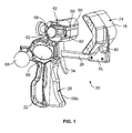
FIG. 1 is a perspective view of a cable stripper which incorporates the features of some example embodiments; -
FIG. 2 is side elevation view of the cable stripper; -
FIG. 3 is an exploded perspective view of the cable stripper; -
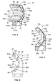
FIG. 4 is a side elevation view of a first body of the cable stripper; -
FIG. 5 is a cross-sectional view of the first body; -
FIG. 6 is a perspective view of a second body of the cable stripper; -
FIG. 7 is a side elevation view of the second body; -
FIG. 8 is a cross-sectional view of the second body; -
FIG. 9 is a side elevation view of a grip of the cable stripper; -
FIG. 10 is a perspective view of the grip; -
FIG. 11 is a perspective view of a portion of the cable stripper; and -
FIG. 12 is a perspective view of another portion of the cable stripper. - While the invention may be susceptible to embodiment in different forms, there is shown in the drawings, and herein will be described in detail, a specific embodiment with the understanding that the present disclosure is to be considered an exemplification of the principles of the invention, and is not intended to limit the invention to that as illustrated and described herein. Therefore, unless otherwise noted, features disclosed herein may be combined together to form additional combinations that were not otherwise shown for purposes of brevity. It will be further appreciated that in some embodiments, one or more elements illustrated by way of example in a drawing(s) may be eliminated and/or substituted with alternative elements within the scope of the disclosure.
- While the terms upper, lower, front, rear and the like are used herein, these are used for ease in description and do not denote a required orientation for use.
- A
cable stripper 20 is provided for stripping a sheath of a cable from the wires within the cable. Thecable stripper 20 includes afirst body 22, asecond body 24 which is moveable relative to thefirst body 22, agrip 26, aslide bar 28, a firstlocking friction plate 30 and itscompression spring 32, a second unlocking friction trigger orplate 34 and itscompression spring 36. - The
first body 22 is formed of metal and includes ahandle 38, amount 40 and ablock 42 which are integrally formed together. Themount 40 is between thehandle 38 and theblock 42. - The
handle 38 is elongated having upper andlower ends rear surfaces side surfaces handle 38 provides an ergonomic feel for the user to grip. Thefront surface 38c is generally arcuate. Therear surface 38d has anupper section 38d' and alower section 38d", thelower section 38d" is spaced farther away from thefront surface 38c than theupper section 38d'. - The
mount 40 is generally square-shaped with front andrear walls lower walls walls 40a-d define a pair of side surfaces. Theupper wall 40c extends between and connects the front andrear walls lower wall 40d is divided into afront section 40d' which extends at an angle from thefront wall 40a, and arear section 40d" which extends at an angle from therear wall 40b; theupper end 38a of thehandle 38 spans the distance between the front andrear sections 40d', 40d". - An
aperture 44 is defined by thewalls 40a-d, theupper end 38a of thehandle 38, and aflange 46 which extends rearwardly from thefront wall 40a a predetermined distance. Acenterline 48 is defined by themount 40 and extends through the front andrear walls flange 46 has anarcuate front end 46a which extends from thefront wall 40a, a planarrear edge 46b and oppositeplanar side walls 46c which define a width therebetween. Therear edge 46b is perpendicular to thecenterline 48. The width of theflange 46 is less than thefront wall 40a, such that a pocket is formed by theflange 46 and thefront wall 40a. One pocket is formed by the rear side of thefront wall 40a and theside wall 46c of theflange 46; the other pocket is formed by the rear side of thefront wall 40a and the opposite side wall 46e of theflange 46. - A
front passageway 50 extends through thefront wall 40a and through theflange 46 and is in communication with theaperture 44. Arear passageway 52 extends through therear wall 40b and is in communication with theaperture 44. The front andrear passageways centerline 48 of themount 40. Thefront passageway 50,aperture 44 andrear passageway 52 form a slide bar passageway into which theslide bar 28 as described herein. Ablind bore 53 is provided in thefront wall 40a and extends rearwardly a predetermined distance. A rear end of thecompression spring 36 seats within theblind bore 53. - The
block 42 is generally formed as a cube and extends upwardly and forwardly from theupper wall 40c of themount 40. Theblock 42 includes front andrear surfaces lower surface 42c which extends from themount 40, anupper surface 42d and a pair ofside surfaces - The
front surface 42a has a centralflat section 42a' which is perpendicular to thecenterline 48 of themount 40, an uppercurved section 42a" extending upwardly from the centralflat section 42a, and alower section 42a'" extending downwardly at an angle from the centralflat section 42a'. Anelongated slot 54 is provided thefront surface 42a, extends between theside surfaces centerline 48 of themount 40. Theslot 54 is formed from an elongated front opening 54a, and a generallycylindrical recess 54b extending reardwardly from the front opening 54a. The ends of theslot 54 are closed by suitable means, such as awall 56 formed by a portion of theblock 42 atside surface 42f and atab 61 which is fastened into theside surface 42e. - A plurality of side-by-
side ball bearings 60 are mounted in theslot 54. Theball bearings 60 are formed as spheres and a portion of each ball bearing 60 extends outwardly from the front opening 54a of theslot 54 and thefront surface 42a of theblock 42, but theball bearings 60 cannot escape through the front opening 54a of theslot 54. Theball bearings 60 are slightly smaller than the diameter of therecess 54b so that theball bearings 60 move freely within theslot 54. Theball bearings 60 may be formed of any suitable material, such as by way of non-limiting example, plastic or metal, and some of theball bearings 60 in theslot 54 may be formed of plastic and others formed of metal. - The conventional cable cutter/
stripper 58 has ablade 59 and anadjustment mechanism 62 for adjusting how far theblade 59 extends outwardly from thefront surface 42a of theblock 42. - The
lower surface 42c of theblock 42 has arecess 64 therein which is proximate to themount 40 and which extends between the side surfaces 42e, 42f. The unlockingfriction plate 34 seats therein as described herein. -
Covers 66 are attached to the side surfaces of thewalls 40a-d by suitable means, such as fasteners. - A revolving
ball knob 68 can be attached to themount 40. - The
slide bar 28 is formed of an elongated metal bar, which preferably has a generally oval cross-section. Theslide bar 28 has front andrear ends 28a, 28b, upper andlower surfaces opposite side surfaces 28e, each of which are planar. Theslide bar 28 seats within the alignedpassageways mount 40 and extends through theaperture 44. Theslide bar 28 can be slid relative to thefirst body 22, along thecenterline 48.Markings 70 are provided along theslide bar 28. - A
ring 72 may be attached to therear end 28b of theslide bar 28 to provide a means for hanging thecable stripper 20 on a bench or other work surface. - The
second body 24 mounts on the front end of theslide bar 28. Thesecond body 24 is formed of metal and has a V-shapedblock 74 attached to amount 76. - The
block 74 is formed of anupper portion 78 and alower portion 80 which are angled relative to each other to form a V-shaped face. In some embodiments, the upper andlower portions lower portions - The
upper portion 78 has front andrear surfaces upper surface 78c, alower edge 78d, which is joined to theupper edge 80d of thelower portion 80, and a pair ofside surfaces elongated slots 82 are provided therear surface 78b of theupper portion 78, eachslot 82 extends between the side surfaces 78e, 78f, and eachslot 82 is perpendicular to thecenterline 48 of themount 40. Eachslot 82 is formed from an elongatedrear opening 82a, and a generallycylindrical recess 82b extending forwardly from therear opening 82a. The ends of theslots 82 are closed by suitable means, such as awall 84 formed by theupper portion 78 and acover 86 which is secured to theside surface 78e of theupper portion 78. - A plurality of side-by-
side ball bearings 88 are mounted in each of theslots 82. Theball bearings 88 are formed as spheres and a portion of eachball bearing 88 extends outwardly from the respectiverear opening 82a of therespective slot 82 and therear surface 78b of theupper portion 78, but theball bearings 88 cannot escape from theslots 82. Theball bearings 88 are slightly smaller than the diameter of therecess 82b so that theball bearings 88 move freely within theslots 82. Theball bearings 88 may be formed of any suitable material, such as by way of non-limiting example, plastic or metal, and some of theball bearings 88 in theslots 82 may be formed of plastic and others formed of metal. - The
lower portion 80 has front andrear surfaces lower surface 80c, anupper edge 80d, which is joined to thelower edge 78d of theupper portion 78, and a pair ofside surfaces elongated slots 90 are provided thefront surface 80b of thelower portion 80, eachslot 90 extends between the side surfaces 80e, 80f, and eachslot 90 is perpendicular to thecenterline 48 of themount 40. Eachslot 90 is formed from an elongatedrear opening 90a, and a generallycylindrical recess 90b extending forwardly from therear opening 90a. The ends of theslots 90 are closed by suitable means, such as awall 92 formed by thelower portion 80 and acover 94 which is secured to theside surface 80e of thelower portion 80. - A plurality of side-by-
side ball bearings 96 are mounted in each of theslots 90. Theball bearings 96 are formed as spheres and a portion of eachball bearing 96 extends outwardly from the respectiverear opening 90a of therespective slot 90 and therear surface 78b of theupper portion 78, but theball bearings 96 cannot escape from theslots 90. Theball bearings 96 are slightly smaller than the diameter of therecess 90b so that theball bearings 96 move freely within theslots 90. Theball bearings 96 may be formed of any suitable material, such as by way of non-limiting example, plastic or metal. In some embodiments, differentrespective ball bearings 96 in theslots 90 may be formed of different materials, such that, for example, in some embodiments someball bearings 96 may be formed of plastic and others may be formed of metal. - A joint 98 is formed between the upper and
lower portions rear surfaces centerline 100 extends along this joint and is perpendicular tocenterline 48. The joint 98 may be curved. Theslots centerline 100. - The
mount 76 extends from thelower surface 80c of thelower portion 80. Themount 76 has a pair oflegs space 104 therebetween. Thespace 104 is slightly wider than the width of theslide bar 28. Theslide bar 28 seats within thespace 104 and thelegs slide bar 28 by suitable means, such as fasteners, so that theblock 74 extends upwardly from theslide bar 28. - When the
second body 24 is attached to theslide bar 28, therear surfaces second body 24 face thefront surface 42a of theblock 42 of thefirst body 22. As such, the row ofball bearings 60 on theblock 42 face the joint 98 between the upper andlower portions second body 24. The lowercurved section 42a□ aligns with thelower portion 80. - The
grip 26 attaches to themount 40 and is rotatable relative to thefirst body 22. Thegrip 26 includes anelongated handle 106 integrally formed with ahead 108 at the upper end thereof. Thehandle 106 is generally U-shaped, with a pair oflegs curved base wall 106c that defines anelongated recess 110. Thebase wall 106c is contoured to enable a user to easily grip thegrip 26 with his/her fingers. Avertical centerline 111 is defined by thehandle 106. Therecess 110 is sized to be slightly wider than the width of thehandle 38 of thefirst body 22. Thehead 108 is formed of twoportions respective legs handle 106 and are separated from each other by aspace 112. Eachportion front surface 114 and a rear surface 116; thecenterline 111 extends through thehead 108. - The
flange 46 of themount 40 seats in thespace 112 between theportions head 108, such that side surfaces of theportions side walls 46c of the pockets formed by theflange 46. The curvedfront surface 114 of eachportion front end 46a of the respective pocket formed by theflange 46. Thehead 108 is attached to themount 40 by a pivot, which may be formed by pegs on the inner surface of thecovers 66 that fit intoblind holes 118. Thehandle 38 is partially seated in therecess 110. - The locking
friction plate 30 and itscompression spring 32 are mounted on theslide bar 28 and within theaperture 44 in thefirst body 22. The lockingfriction plate 30 is preferably rectangular in cross-section and has opposite front and rear surfaces. The lockingfriction plate 30 has anaperture 120 therethrough, having atop wall 120a, abottom wall 120b andopposite side walls 120c. Theaperture 120 has a dimension between thetop wall 120a and thebottom wall 120b which is sized to be slightly larger than theslide bar 28 which seats therethrough. Anupper portion 30a of the lockingfriction plate 30 extends upwardly from theslide bar 28, and alower portion 30b of the lockingfriction plate 30 extends downwardly from theslide bar 28. - The
compression spring 32 encircles theslide bar 28. Thecompression spring 32 seats in theaperture 44 between the lockingfriction plate 30 and the front surface of therear wall 40b. - The unlocking
friction plate 34 seats on theslide bar 28 and is positioned between themount 76 of thesecond body 24 and thefront surface 40a of themount 40 of thefirst body 22. The unlockingfriction plate 34 is formed of an elongated member having anupper end 34a, alower end 34b, a planarupper portion 34c extending from theupper end 34a to alower portion 34d which is curved relative to theupper portion 34c. Theupper portion 34c has anaperture 122 therethrough, having atop wall 122a, abottom wall 122b andopposite side walls 122c. Theaperture 122 has a dimension between thetop wall 122a and thebottom wall 122b which is sized to be slightly larger than theslide bar 28 which seats therethrough. Theupper end 34a of the unlockingfriction plate 34 seats in therecess 64 in theblock 42 of thefirst body 22. Thelower portion 34d of the unlockingfriction plate 34 extends downwardly from theslide bar 28 and is proximate to thegrip 26. - The rear end of the
compression spring 36 seats within the blind bore 53 and the front end abuts against theupper portion 34c of the unlockingfriction plate 34. The front end of thecompression spring 36 presses against the unlockingfriction plate 34. - In an at-rest condition (the
grip 26 is not depressed), thecenterline 111 of thegrip 28 is perpendicular to thecenterline 48 of thefirst body 22, the lockingfriction plate 30 is generally perpendicular to theslide bar 28 and abuts against the planarrear edge 46b of theflange 46 and abuts against thehead 108 of thegrip 26, theupper portion 34c of the unlockingfriction plate 34 is angled relative to theslide bar 28, and the compression springs 32, 36 are in their expanded states. Theupper edge 120a of theaperture 120 through the lockingfriction plate 30 is engaged with theupper surface 28c of theslide bar 28. Since theaperture 120 through the lockingfriction plate 30 is slightly larger than theslide bar 28, thelower edge 120b of theaperture 120 through the lockingfriction plate 30 is not engaged with thelower surface 28d of theslide bar 28 such that a gap is provided therebetween. The angle of unlockingfriction plate 34 causes the rearupper edge 122a and the front oflower edge 122b to make contact with theslide bar 28. This contact, in addition to the contact ofsurface 34c with opening 64 prevents the movement of theslide bar 28 in the forward direction. The frictional engagement is easily overcome if the user moves theslide bar 28 in the rearward direction due to the same angle of the unlockingfriction plate 34. - When the
first body 22 and thesecond body 24 are separated from each other, the cable (not shown) to be stripped is inserted between theblocks - In use, the
grip 26 is depressed to rotate and move thegrip 26 toward thehandle 38 of thefirst body 22. When this rotation occurs, the curvedfront surface 114 of eachportion front end 46a of the respective pocket formed by theflange 46, and thehandle 38 enters into therecess 110 in thegrip 26. Thehead 108 of thegrip 26 engages thelower portion 30b of the lockingfriction plate 30 and moves thelower portion 30b rearwardly, away from therear edge 46b of theflange 46, thereby moving the lockingfriction plate 30 at an angle relative to therear edge 46b of theflange 46, and compressing thespring 32. - Upon continued depression of the
grip 26, thelower portion 30b of the lockingfriction plate 30 continues to move rearwardly. When the lockingfriction plate 30 reaches a predetermined angle, theslide bar 28 fills the space in theaperture 120 of the lockingfriction plate 30 such that the lockingfriction plate 30 and theslide bar 28 become wedged together. The frictional engagement between the unlockingfriction plate 34 and theslide bar 28 is overcome by this force so that theslide bar 28 can slide relative to the unlockingfriction plate 34. Further depression of thegrip 26 causes theslide bar 28, and thesecond body 24 mounted thereon, to move rearwardly with the rearward movement of the lockingfriction plate 30 and further compression of thecompression spring 32, such that thesecond body 24 moves toward thefirst body 22. When thegrip 26 is released, the compression springs 32, 36 returns to their expanded states, thereby disengaging the lockingfriction plate 30 from theslide bar 28 and frictionally re-engaging the unlockingfriction plate 34 with theslide bar 28, and returning the lockingfriction plate 30 and the unlockingfriction plate 34 to the at-rest positions. This can be repeated over and over again to move thesecond body 24 toward thefirst body 22 to clamp the cable in a ratcheting-type movement. This configuration allows a user to easily clamp the cable using a single hand. - When the cable is clamped between the
blocks ball bearings ball bearings ball bearings block 74. Theblocks block 74 as a result of the engagement of theball bearings block 74 in order to sufficiently capture a cable that would make contact with thebearings ball bearings ball bearings block 74, but rather make contact withball bearings 60 withsurfaces - During the stripping of the cable with the
cable stripper 20, thecable stripper 20 is rotated around the cable to cut the sheath of the cable using thecutting blade 59. This may be accomplished by the user placing one hand on the cable and his/her hand on the revolvingball knob 68. Theball bearings blocks ball bearings ball bearings ball bearings - When the cable has been stripped using the
cable stripper 20, thesecond body 24 is quickly and easily moved away from the clamped position (proximate to the first body 22) in a non-ratcheting movement by using the unlockingfriction plate 34 to resize thecable stripper 20. With thegrip 26 released, the user depresses the unlockingfriction plate 34 to move thelower portion 34d to be proximate to thegrip 26, thereby compressing thespring 36. This depression of the unlockingfriction plate 34 disengages the frictional engagement between the unlockingfriction plate 34 and theslide bar 28 and allows the user to grasp theblock 74 and pull theslide bar 28 forwardly such that thesecond body 24 moves away from thefirst body 22. When the desired position of thesecond body 24 is achieved, the user releases the unlockingfriction plate 34, which causes thespring 36 to expand, and move the unlockingfriction plate 34 back to the at-rest position. As a result, theslide bar 28 is frictionally engaged with the unlockingfriction plate 34 so that another cable to be stripped can be positioned between theblocks - The
second body 24 can be quickly and easily moved toward the clamped position. The user pushes thebodies slide bar 28 rearwardly until thesecond body 24 abuts the cable. The unlockingfriction plate 34 is overcome during this pushing. Thereafter, thegrip 26 is depressed to ratchet thesecond body 24 toward thefirst body 22 as described herein to securely clamp the cable for stripping. - In use, the major thumb pad of the user's hand engages the
lower section 38d" of therear surface 38d and the user's thumb wraps around theupper section 38d' of therear surface 38d. The thumb of the user engages against therear section 40d" of thelower wall 40d of themount 40. The fingers of the user wrap around thebase wall 106c of thegrip 26. This provides a comfortable grip for the user. - As a result of the structure, the
cable stripper 20 is easy to use, it can be quickly resized for a wide range of cable sizes, and it can be secured or released from a cable with one-handed operation. Theblocks cutting blade 59 at a consistent cutting depth when thecable stripper 20 is rotated around the cable. - While the conventional cable cutter/
stripper 58 is shown as described as being secured to theside surface 42e of theblock 42 of thefirst body 22, the conventional cable cutter/stripper 58 could instead be attached to thesecond body 24. - While particular embodiments are illustrated in and described with respect to the drawings, it is envisioned that those skilled in the art may devise various modifications without departing from the spirit and scope of the appended claims. It will therefore be appreciated that the scope of the disclosure and the appended claims is not limited to the specific embodiments illustrated in and discussed with respect to the drawings and that modifications and other embodiments are intended to be included within the scope of the disclosure and appended claims. Moreover, although the foregoing descriptions and the associated drawings describe example embodiments in the context of certain example combinations of elements and/or functions, it should be appreciated that different combinations of elements and/or functions may be provided by alternative embodiments without departing from the scope of the disclosure and the appended claims.
Claims (15)
- A cable stripper comprising:first and second bodies;a slide bar connecting the first body to the second body;a plate mounted on the slide bar and being moveable relative to the slide bar and to the bodies, the plate having an aperture through which the slide bar extends, the aperture being sized to be greater than a dimension of the slide bar which extends therethrough;a spring mounted between the plate and the first body; anda grip rotationally attached to the first body and engaged with the plate;wherein when the grip is depressed, the grip engages with the plate and the plate engages with the slide bar which causes the slide bar and the second body to move relative to the first body.
- The cable stripper of claim 1, wherein the spring encircles the slide bar and engages between the plate and the first body and / or wherein the slide bar extends through a passageway formed though the first body and the plate is seated within the passageway and/or wherein the first body includes a handle and /or wherein one of said bodies includes a blade attached thereto.
- The cable stripper of claim 1, further including a second plate mounted on the slide bar and engaged with the first body, the second plate being moveable relative to the slide bar and to the bodies, the second plate having an aperture through which the slide bar extends, the aperture being sized to be greater than a dimension of the slide bar which extends therethrough;
a second spring mounted between the second plate and the first body; and
wherein when the second plate is rotated relative to the slide bar, the slide bar can move relative to the second plate by a user grasping either the slide bar or the second body and moving the slide bar and second body relative to the first body. - The cable stripper of claim 3, wherein the second plate has an upper end which is seated in a recess in the first body.
- The cable stripper of claim 4, wherein a rear end of the second spring seats within a bore of the first body and a front end of the spring is secured to the second plate.
- The cable stripper of claim 1, wherein
the spring encircles the slide bar and engages between the plate and the first body; and
the slide bar extends through a passageway formed though the first body and the plate is seated within the passageway. - The cable stripper of claim 6, further including a second plate mounted on the slide bar and engaged with the first body, the second plate being moveable relative to the slide bar and to the bodies, the second plate having an aperture through which the slide bar extends, the aperture being sized to be greater than a dimension of the slide bar which extends therethrough;
a second spring mounted between the second plate and the first body; and
wherein when the second plate is rotated relative to the slide bar, the slide bar can move relative to the second plate by a user grasping either the slide bar or the second body and moving the slide bar and second body relative to the first body. - The cable stripper of claim 7, wherein the second plate has an upper end which is seated in a recess in the first body, and a rear end of the second spring seats within a bore of the first body and a front end of the spring is secured to the second plate.
- The cable stripper of claim 1, wherein the first and second bodies have a plurality of ball bearings mounted therein, and wherein a cable engages with the ball bearings when engaged between the first and second bodies.
- The cable stripper of claim 1, wherein the second body has an upper portion and a lower portion which are angled relative to each other, and further comprising a plurality of ball bearings mounted in the upper portion, and a plurality of ball bearings mounted in the lower portion, and wherein a cable engages with the ball bearings when engaged between the first and second bodies.
- The cable stripper of claim 10, further comprising a plurality of ball bearings mounted in the first body, and wherein the cable engages with the ball bearings of the first body when engaged between the first and second bodies.
- A cable stripper comprising:first and second bodies, said second body being moveable relative to said first body; anda plurality of spherical ball bearings mounted in said first and second bodies, and wherein a cable engages with the ball bearings when engaged between the first and second bodies.
- The cable stripper of claim 12, wherein the second body has an upper portion and a lower portion which are angled relative to each other, and wherein ball bearings are mounted in the upper portion, and ball bearings are mounted in the lower portion.
- The cable stripper of claim 12, wherein the ball bearings are in rows in each of the first and second bodies and/or wherein the ball bearings are seated in slots, each slot having a front opening which prevents the ball bearings from passing therethrough and/or wherein the ball bearings are formed from one of plastic and metal.
- The cable stripper of claim 12, wherein some of the ball bearings are formed from plastic and some of the ball bearings are formed of metal.
Applications Claiming Priority (1)
| Application Number | Priority Date | Filing Date | Title |
|---|---|---|---|
| US201361882816P | 2013-09-26 | 2013-09-26 |
Publications (2)
| Publication Number | Publication Date |
|---|---|
| EP2854244A2 true EP2854244A2 (en) | 2015-04-01 |
| EP2854244A3 EP2854244A3 (en) | 2015-07-01 |
Family
ID=51609953
Family Applications (1)
| Application Number | Title | Priority Date | Filing Date |
|---|---|---|---|
| EP14185889.4A Withdrawn EP2854244A3 (en) | 2013-09-26 | 2014-09-23 | Cable stripper |
Country Status (3)
| Country | Link |
|---|---|
| US (1) | US20150082639A1 (en) |
| EP (1) | EP2854244A3 (en) |
| CN (1) | CN104518459A (en) |
Cited By (1)
| Publication number | Priority date | Publication date | Assignee | Title |
|---|---|---|---|---|
| CN104753003A (en) * | 2015-04-24 | 2015-07-01 | 国家电网公司 | Chamfering tool for cable semiconductor layer |
Families Citing this family (4)
| Publication number | Priority date | Publication date | Assignee | Title |
|---|---|---|---|---|
| FR2992110B3 (en) * | 2012-06-14 | 2014-12-12 | Stanley Works Europe Gmbh | TOOL FOR STRIPPING ELECTRIC CABLES |
| US10630062B2 (en) | 2017-02-24 | 2020-04-21 | Ripley Tools, Llc | Adjustable wire stripper |
| US10459185B2 (en) * | 2017-04-25 | 2019-10-29 | Ripley Tools, Llc | Fiber optic cable buffer tube mid-span access tool |
| DE112023002147A5 (en) * | 2022-06-28 | 2025-04-24 | Weicon Gmbh & Co Kg | Cable knife for flat cables |
Citations (3)
| Publication number | Priority date | Publication date | Assignee | Title |
|---|---|---|---|---|
| WO2005115690A1 (en) * | 2004-05-19 | 2005-12-08 | Irwin Industrial Tools Gmbh | Chucking and/or expansion tool having a push or pull rod |
| US7140582B1 (en) * | 2004-11-01 | 2006-11-28 | Ronald Miller | Quick connect ladder clamp |
| US20070089579A1 (en) * | 2005-10-24 | 2007-04-26 | O'neal Michael | Cutting tool, method of making the same and method of using the same |
Family Cites Families (9)
| Publication number | Priority date | Publication date | Assignee | Title |
|---|---|---|---|---|
| US3707099A (en) * | 1970-10-15 | 1972-12-26 | Edmund Petz | Head-on wire stripping tool |
| JPS5936095Y2 (en) * | 1974-07-24 | 1984-10-05 | カブシキガイシヤ イズミセイキセイサクシヨ | Electric wire coating stripping tool |
| US4926722A (en) * | 1988-08-19 | 1990-05-22 | Petersen Manufacturing Co., Inc. | Quick-action bar clamp |
| US5161787A (en) * | 1991-11-08 | 1992-11-10 | Hobday Harold W | Clamping device |
| US5713249A (en) * | 1993-03-06 | 1998-02-03 | Liversidge; Barry Peter | Wire stripper |
| CA2137474A1 (en) * | 1994-12-02 | 1996-06-03 | Rene Benoit | Cut and strip tool for insulated conductive wires |
| US5669275A (en) * | 1995-08-18 | 1997-09-23 | Mills; Edward Otis | Conductor insulation remover |
| US5733213A (en) * | 1997-04-07 | 1998-03-31 | Colarusso; Michael | Roller hockey puck and method of making the same |
| DE10027315B4 (en) * | 2000-06-05 | 2004-02-12 | PF Schweißtechnologie GmbH | Peeling device for cylindrical objects |
-
2014
- 2014-09-19 US US14/490,854 patent/US20150082639A1/en not_active Abandoned
- 2014-09-23 EP EP14185889.4A patent/EP2854244A3/en not_active Withdrawn
- 2014-09-26 CN CN201410505276.5A patent/CN104518459A/en active Pending
Patent Citations (3)
| Publication number | Priority date | Publication date | Assignee | Title |
|---|---|---|---|---|
| WO2005115690A1 (en) * | 2004-05-19 | 2005-12-08 | Irwin Industrial Tools Gmbh | Chucking and/or expansion tool having a push or pull rod |
| US7140582B1 (en) * | 2004-11-01 | 2006-11-28 | Ronald Miller | Quick connect ladder clamp |
| US20070089579A1 (en) * | 2005-10-24 | 2007-04-26 | O'neal Michael | Cutting tool, method of making the same and method of using the same |
Cited By (1)
| Publication number | Priority date | Publication date | Assignee | Title |
|---|---|---|---|---|
| CN104753003A (en) * | 2015-04-24 | 2015-07-01 | 国家电网公司 | Chamfering tool for cable semiconductor layer |
Also Published As
| Publication number | Publication date |
|---|---|
| US20150082639A1 (en) | 2015-03-26 |
| CN104518459A (en) | 2015-04-15 |
| EP2854244A3 (en) | 2015-07-01 |
Similar Documents
| Publication | Publication Date | Title |
|---|---|---|
| US9391435B2 (en) | Cable stripper and cutting assembly for stripping a cable | |
| US20150082639A1 (en) | Cable stripper | |
| US6128976A (en) | Single drop trimmer | |
| TWI320984B (en) | Adjustable stripping tool | |
| US20130091713A1 (en) | Scissors structure with adjustable opening | |
| US4206663A (en) | Lineman snake gripper | |
| US7665389B2 (en) | Multitool with wire stripping element | |
| US20070028461A1 (en) | Circular cutter | |
| US6253641B1 (en) | Single drop trimmer with limited cartridge release | |
| US10449663B2 (en) | Ergonomic handle device for holding tools | |
| US10418796B2 (en) | Cable stripper | |
| US20190372290A1 (en) | Crimping Tool | |
| US4805302A (en) | Wire stripper | |
| US6526661B1 (en) | Cutting and stripping tool | |
| TWM521831U (en) | Multi-function wire stripping hand tool and kit | |
| US11025024B2 (en) | Crimping hand tool | |
| CA1135033A (en) | Wire stripper | |
| EP1745815A1 (en) | Side loading needle depth stop | |
| US20050284534A1 (en) | Cutting device for a metal band bundling apparatus | |
| US2435562A (en) | Ferrule crimping tool | |
| EP1246714A1 (en) | Tool handle extension connector | |
| US20080110029A1 (en) | Knives with wire cutter | |
| JPH07501440A (en) | Insulation stripping devices for electrical wires and/or conductors | |
| US7913394B2 (en) | Cable sheath splitter | |
| US5009005A (en) | Cable stripper |
Legal Events
| Date | Code | Title | Description |
|---|---|---|---|
| PUAI | Public reference made under article 153(3) epc to a published international application that has entered the european phase |
Free format text: ORIGINAL CODE: 0009012 |
|
| 17P | Request for examination filed |
Effective date: 20140923 |
|
| AK | Designated contracting states |
Kind code of ref document: A2 Designated state(s): AL AT BE BG CH CY CZ DE DK EE ES FI FR GB GR HR HU IE IS IT LI LT LU LV MC MK MT NL NO PL PT RO RS SE SI SK SM TR |
|
| AX | Request for extension of the european patent |
Extension state: BA ME |
|
| PUAL | Search report despatched |
Free format text: ORIGINAL CODE: 0009013 |
|
| AK | Designated contracting states |
Kind code of ref document: A3 Designated state(s): AL AT BE BG CH CY CZ DE DK EE ES FI FR GB GR HR HU IE IS IT LI LT LU LV MC MK MT NL NO PL PT RO RS SE SI SK SM TR |
|
| AX | Request for extension of the european patent |
Extension state: BA ME |
|
| RIC1 | Information provided on ipc code assigned before grant |
Ipc: H02G 1/12 20060101AFI20150527BHEP |
|
| R17P | Request for examination filed (corrected) |
Effective date: 20151222 |
|
| RBV | Designated contracting states (corrected) |
Designated state(s): AL AT BE BG CH CY CZ DE DK EE ES FI FR GB GR HR HU IE IS IT LI LT LU LV MC MK MT NL NO PL PT RO RS SE SI SK SM TR |
|
| RAP1 | Party data changed (applicant data changed or rights of an application transferred) |
Owner name: TEXTRON INNOVATIONS INC. |
|
| 17Q | First examination report despatched |
Effective date: 20170331 |
|
| STAA | Information on the status of an ep patent application or granted ep patent |
Free format text: STATUS: THE APPLICATION IS DEEMED TO BE WITHDRAWN |
|
| 18D | Application deemed to be withdrawn |
Effective date: 20170811 |