EP2854215A1 - Antenna arrangement having an antenna unit and connector unit - Google Patents
Antenna arrangement having an antenna unit and connector unit Download PDFInfo
- Publication number
- EP2854215A1 EP2854215A1 EP14186129.4A EP14186129A EP2854215A1 EP 2854215 A1 EP2854215 A1 EP 2854215A1 EP 14186129 A EP14186129 A EP 14186129A EP 2854215 A1 EP2854215 A1 EP 2854215A1
- Authority
- EP
- European Patent Office
- Prior art keywords
- antenna
- antenna arrangement
- electrically insulating
- arrangement according
- connector
- Prior art date
- Legal status (The legal status is an assumption and is not a legal conclusion. Google has not performed a legal analysis and makes no representation as to the accuracy of the status listed.)
- Granted
Links
Images

Classifications
-
- H—ELECTRICITY
- H01—ELECTRIC ELEMENTS
- H01Q—ANTENNAS, i.e. RADIO AERIALS
- H01Q9/00—Electrically-short antennas having dimensions not more than twice the operating wavelength and consisting of conductive active radiating elements
- H01Q9/04—Resonant antennas
- H01Q9/30—Resonant antennas with feed to end of elongated active element, e.g. unipole
-
- H—ELECTRICITY
- H01—ELECTRIC ELEMENTS
- H01R—ELECTRICALLY-CONDUCTIVE CONNECTIONS; STRUCTURAL ASSOCIATIONS OF A PLURALITY OF MUTUALLY-INSULATED ELECTRICAL CONNECTING ELEMENTS; COUPLING DEVICES; CURRENT COLLECTORS
- H01R13/00—Details of coupling devices of the kinds covered by groups H01R12/70 or H01R24/00 - H01R33/00
- H01R13/02—Contact members
- H01R13/03—Contact members characterised by the material, e.g. plating, or coating materials
- H01R13/035—Plated dielectric material
-
- H—ELECTRICITY
- H01—ELECTRIC ELEMENTS
- H01Q—ANTENNAS, i.e. RADIO AERIALS
- H01Q1/00—Details of, or arrangements associated with, antennas
- H01Q1/27—Adaptation for use in or on movable bodies
- H01Q1/32—Adaptation for use in or on road or rail vehicles
- H01Q1/3208—Adaptation for use in or on road or rail vehicles characterised by the application wherein the antenna is used
-
- H—ELECTRICITY
- H01—ELECTRIC ELEMENTS
- H01Q—ANTENNAS, i.e. RADIO AERIALS
- H01Q9/00—Electrically-short antennas having dimensions not more than twice the operating wavelength and consisting of conductive active radiating elements
- H01Q9/04—Resonant antennas
- H01Q9/30—Resonant antennas with feed to end of elongated active element, e.g. unipole
- H01Q9/32—Vertical arrangement of element
- H01Q9/36—Vertical arrangement of element with top loading
-
- H—ELECTRICITY
- H01—ELECTRIC ELEMENTS
- H01R—ELECTRICALLY-CONDUCTIVE CONNECTIONS; STRUCTURAL ASSOCIATIONS OF A PLURALITY OF MUTUALLY-INSULATED ELECTRICAL CONNECTING ELEMENTS; COUPLING DEVICES; CURRENT COLLECTORS
- H01R2201/00—Connectors or connections adapted for particular applications
- H01R2201/02—Connectors or connections adapted for particular applications for antennas
-
- H—ELECTRICITY
- H01—ELECTRIC ELEMENTS
- H01R—ELECTRICALLY-CONDUCTIVE CONNECTIONS; STRUCTURAL ASSOCIATIONS OF A PLURALITY OF MUTUALLY-INSULATED ELECTRICAL CONNECTING ELEMENTS; COUPLING DEVICES; CURRENT COLLECTORS
- H01R24/00—Two-part coupling devices, or either of their cooperating parts, characterised by their overall structure
- H01R24/38—Two-part coupling devices, or either of their cooperating parts, characterised by their overall structure having concentrically or coaxially arranged contacts
- H01R24/40—Two-part coupling devices, or either of their cooperating parts, characterised by their overall structure having concentrically or coaxially arranged contacts specially adapted for high frequency
Definitions
- the present invention relates to an antenna arrangement having an antenna unit and a connector unit for electrically connecting the antenna unit to an associated counter-connector unit.
- Such antennae are widespread in particular in the automotive field and serve to transmit an extremely wide range of signals.
- monopole antennae are often used nowadays.
- Such a monopole antenna comprises in its most simple form a straight cylindrical conductor, which is excited at a base location with respect to earth.
- the electrical properties of such antennae are dependent both on the geometry of the monopole element and on the ground surface.
- the length of the monopole is approximately a quarter of the wavelength which is intended to be transmitted.
- antenna elements which enable wireless communication between those vehicles which are provided with so-called on-board units.
- Such an on-board unit can detect, for example, information relating to current traffic situations (for example, traffic jams, icy roads or construction works) and vehicle-specific parameters (such as the speed, the movement direction, the acceleration, the external temperature or the operating status of the windscreen wipers). This information can then be transmitted via a transmission device to other vehicles in the same geographical region, as long as they are provided with corresponding on-board units.
- a receiver unit of such an on-board unit can subsequently evaluate the information from more than one vehicle in order to increase the traffic safety and the efficiency of each vehicle. Therefore, antennae as used for communication between vehicles are subject to specific requirements.
- the emission pattern has to have precisely defined properties: in particular it is advantageous for the antenna element to have undirected emission.
- the term "undirected” is intended to be understood to mean that the antenna element has a round beam characteristic in the horizontal plane, that is to say that it emits uniform power in all directions perpendicularly to the line of extent of the antenna element.
- the present invention is based on the notion of constructing a connector unit which is securely connected to the antenna unit in such a manner that components of the antenna unit are carried by the electrically insulating connector housing.
- the structural length of the entire antenna unit is thereby shortened accordingly.
- the antenna unit has a conductor rod and a folded-top element and the connector unit has a coaxial plug type connector having an inner conductor, an outer conductor and an electrically insulating housing.
- the conductor rod is connected to the inner conductor of the coaxial plug type connector and the folded-top element is formed by an electrically conductive coating of the electrically insulating housing.
- the antenna arrangement further has a roof capacitor which is connected to the conductor rod in a conductive manner at an end which is remote from the connector unit.
- This roof capacitor is constructed in an extensive and substantially rotationally symmetrical manner.
- such a roof capacitor can be used to influence the electrically effective length of the antenna unit.
- the roof capacitor can in this instance be constructed as a rotationally symmetrical disc, but also as an arrangement comprising a large number of rings about such a disc according to EP 1445828 A2 .
- the roof capacitor can be produced in a particularly simple manner when it is applied as an electrically conductive coating to an electrically insulating protective sheath which at least partially surrounds the conductor rod. Since the protective sheath ensures the mechanical stability, any structures may be selected for the roof capacitor.
- a particularly efficient manner of producing both the housing structure with the electrically conductive coating and the roof capacitor on the electrically insulating protective sheath is the production as a Molded Interconnect Device (MID).
- MID Molded Interconnect Device
- a Molded Interconnect Device is generally a preferably injection-moulded plastics material component which combines both electrical and mechanical functionalities in a single component.
- the production of MIDs is a relatively new field with an extremely large potential for industrial applications, in particular in the automotive industry. For example, using single or multi-component injection-moulding methods and subsequent selective metal coating, almost any structures can be produced.
- MID techniques in particular afford the advantage of extensive miniaturisation and a substantial reduction of production costs in comparison with many existing methods.
- the MID technology also affords the possibility of producing completely new types of product designs. For the production of MIDs there are a large number of process sequences and the technology is still developing rapidly.
- thermoplastic cast component which contains metal particles and subsequently carrying out a currentless metal deposition. This process is generally known as Laser Direct Structuring (LDS).
- LDS Laser Direct Structuring
- PVD physical vapour deposition
- metal structures can also be pressed directly under the action of heat on the three-dimensional surface of an injection-moulded plastics component. With so-called two-dimensional injection-moulding methods, coatable and non-coatable polymers are combined in an injection-moulding method and the metal coating is bonded only to the coatable polymer.
- a laser-sensitive polymer can also be combined with a non-coatable polymer and the laser sensitive-polymer is subsequently structured before the metal coating.
- the desired metal structures can also be inserted into the injection-moulding mould as prefabricated components and be embedded in the plastics material component during the injection-moulding method.
- flexible polymer films can also be injected with printed metal coatings as so-called inserts.
- the present invention can be used in a particularly advantageous manner together with WiFi applications and it is, for example, advantageous to size the antenna arrangement for receiving frequencies of 2.4 GHz in this instance.
- FAKRA Freach Vietnamese Automobil
- FAKRA is the "Fach Vietnamese Automobil” (Automotive Technical Body) of the German Institute for Standardisation which represents international standardisation interests in the automotive sector.
- the FAKRA standard provides a system which is based on mechanical coding and colour coding for correct fitting of connectors.
- the same socket projections can only be connected to identical connector recesses. Reliable positioning of the locking system of connector housings is facilitated by means of securing according to the FAKRA standard to the socket housing and a lock which cooperates therewith on the connector housing.
- FIG. 1 An example of a plug type connector which can be used in an antenna arrangement according to the present invention is described in detail in DE 10 2012 201565 A1 , in particular with reference to Figures 1 and 3 and 5.
- the present invention is based in this instance on the notion of adapting such a known housing, and in particular the connector arrangement, using an appropriate metal coating technology in such a manner that elements of the antenna unit are produced on the connector housing. As already mentioned, this can be carried out in particular using an MID technology during the injection-moulding process.
- the metal coating which is applied to the plug type connector housing can act, on the one hand, as a reference ground and, on the other hand, balun functions can be carried out therewith.
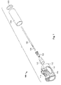
- Figure 1 shows in the form of an exploded view an antenna arrangement 100 according to an exemplary embodiment of the present invention.
- the antenna arrangement 100 comprises an antenna unit having a conductor rod 102 and a folded-top element 104.
- the conductor rod 102 is a preferably cylindrical metal component and is connected to the inner conductor 106 of the FAKRA coaxial plug type connector, for example, by means of a crimp connection.
- the coaxial plug type connector has, as can be seen from DE 10 2012 201565 A1 , a dielectric 108 which surrounds the inner conductor 106 and an outer conductor 110 which is electrically insulated from the inner conductor 106 by means of the dielectric 108.
- the connector unit has an electrically insulating housing 112 which is at least partially surrounded by an outer metal coating which acts as a folded-top element 104.
- the metal coating is indicated with cross-hatching.
- no metal coating is provided, for example, in the region of the locking device 114 and the lock 116. Of course, however, these regions may also be metal-coated should this be necessary.
- the connector unit is a coaxial plug type connector having a connector pin, whilst the plug type counter-connector (not shown) constitutes the corresponding socket element.
- the conductor rod 102 could also be connected to a socket element.
- the present embodiment is based on only one releasable plug type connection.
- other connector housings may also be provided with the metal coating according to the invention, for example, in combination with press-fitting or solder connections.
- the antenna arrangement further has a preferably electrically insulating protective sheath 118.
- This may, for example, be produced as an injection-moulded component of plastics material.
- the electrically insulating protective sheath 118 a metal structure which acts as a roof capacitor 120.
- a roof capacitor 120 opens up the possibility of electrically extending the antenna.
- the resonance frequency of a monopole is indirectly proportional to the length thereof.
- An electrical extension of the antenna means that the length of the antenna is shorter than would be required by the desired resonance frequency. Owing to a specific arrangement, it is then ensured that the antenna is nonetheless in resonance at the desired frequency. This is understood to be “electrical extension" in an antenna.
- the roof capacitor 120 can, for example, be produced on the protective sheath 118 using an MID method and can be connected to the conductor rod 102 in an electrically conductive manner by means of a solder connection.
- the roof capacitor 120 is constructed as a circular continuous conductive disc.
- the advantages of the MID method are based on the fact that any metal structures can also be produced on a three-dimensional protective sheath member which is constructed in a more complex manner.
- the folded-top element 104 and the roof capacitor 120 can be produced according to all known MID metal-coating technologies on the associated plastics material component in each case, that is to say, the housing 112 and the protective sheath 118.
- Figure 2 shows the completely assembled antenna arrangement 100 in a rotated view. Owing to the inclusion of the connector in the construction of the antenna unit, a particularly compact structure can be achieved. For example, the arrangement from Figure 2 has an overall length of only little more than 5 cm.
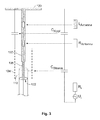
- FIG. 5 is a schematic illustration of an equivalent electrical circuit diagram of the antenna arrangement 100.
- the 50 ⁇ input location is designated 122.
- the folded-top element 104 (which is also referred to as a "sleeve") is not connected to the antenna in an electrically conductive manner, but is only coupled in a capacitive manner both to the outer conductor 110 and to the roof capacitor 120.
- the significant parameters of the antenna circuit are consequently, in addition to the ohmic resistance of the antenna and the inductivity L Antenna , the capacitance of the roof capacitor C Roof and the capacitance of the folded-top element C Sleeve .
- R i and U i refer to the input voltage and the internal resistance of the connected signal source.
- a plastics material connector housing is provided with a corresponding metal coating, for example, using an MID process. This metal structure is part of the antenna structure and does not take up any additional space.
- both the roof capacitor for the monopole and the required ground reference are produced using an MID method.
- the overall length can be reduced by approximately 20% in comparison with a separate construction of the reference ground and plug type connector.
- the antenna arrangement according to the invention can be accommodated more readily.
Landscapes
- Details Of Aerials (AREA)
Description
- The present invention relates to an antenna arrangement having an antenna unit and a connector unit for electrically connecting the antenna unit to an associated counter-connector unit.
- Such antennae are widespread in particular in the automotive field and serve to transmit an extremely wide range of signals. In particular for multimedia applications having high data rates, monopole antennae are often used nowadays. Such a monopole antenna comprises in its most simple form a straight cylindrical conductor, which is excited at a base location with respect to earth. The electrical properties of such antennae are dependent both on the geometry of the monopole element and on the ground surface. The length of the monopole is approximately a quarter of the wavelength which is intended to be transmitted.
- In general, for example, for communication between vehicles, there are used special antenna elements which enable wireless communication between those vehicles which are provided with so-called on-board units. Such an on-board unit can detect, for example, information relating to current traffic situations (for example, traffic jams, icy roads or construction works) and vehicle-specific parameters (such as the speed, the movement direction, the acceleration, the external temperature or the operating status of the windscreen wipers). This information can then be transmitted via a transmission device to other vehicles in the same geographical region, as long as they are provided with corresponding on-board units. A receiver unit of such an on-board unit can subsequently evaluate the information from more than one vehicle in order to increase the traffic safety and the efficiency of each vehicle. Therefore, antennae as used for communication between vehicles are subject to specific requirements.
- On the one hand, the emission pattern has to have precisely defined properties: in particular it is advantageous for the antenna element to have undirected emission. In this instance, the term "undirected" is intended to be understood to mean that the antenna element has a round beam characteristic in the horizontal plane, that is to say that it emits uniform power in all directions perpendicularly to the line of extent of the antenna element.
- On the other hand, strict requirements are placed on a vehicle antenna in terms of the dimensions and shape of the antenna element and in particular the structural size has to be as small as possible. In particular, it is mostly necessary for the antenna element to be able to be fitted in existing vehicle roof antenna housings.
- Furthermore, with such antenna arrangements, there is in most cases the requirement for them to be connected to an already existing counter-connector, in particular a coaxial plug type connector, via a connector arrangement.
- There is therefore the requirement to provide an antenna arrangement which can be contacted by means of a connector arrangement, which can be produced in the most simple manner possible and which can further be miniaturised to the greatest possible extent.
- This object is achieved with the subject-matter of the independent patent claims. Advantageous developments of the present invention are set out in the dependent patent claims.
- The present invention is based on the notion of constructing a connector unit which is securely connected to the antenna unit in such a manner that components of the antenna unit are carried by the electrically insulating connector housing. The structural length of the entire antenna unit is thereby shortened accordingly.
- In particular, the antenna unit has a conductor rod and a folded-top element and the connector unit has a coaxial plug type connector having an inner conductor, an outer conductor and an electrically insulating housing.
- According to the invention, the conductor rod is connected to the inner conductor of the coaxial plug type connector and the folded-top element is formed by an electrically conductive coating of the electrically insulating housing. According to an advantageous development of the present invention, the antenna arrangement further has a roof capacitor which is connected to the conductor rod in a conductive manner at an end which is remote from the connector unit. This roof capacitor is constructed in an extensive and substantially rotationally symmetrical manner. As is generally known, such a roof capacitor can be used to influence the electrically effective length of the antenna unit. The roof capacitor can in this instance be constructed as a rotationally symmetrical disc, but also as an arrangement comprising a large number of rings about such a disc according to
EP 1445828 A2 . When the roof capacitor is configured in a corresponding manner, it is possible to achieve, for example, operational ability at different frequencies. - The roof capacitor can be produced in a particularly simple manner when it is applied as an electrically conductive coating to an electrically insulating protective sheath which at least partially surrounds the conductor rod. Since the protective sheath ensures the mechanical stability, any structures may be selected for the roof capacitor.
- A particularly efficient manner of producing both the housing structure with the electrically conductive coating and the roof capacitor on the electrically insulating protective sheath is the production as a Molded Interconnect Device (MID).
- A Molded Interconnect Device is generally a preferably injection-moulded plastics material component which combines both electrical and mechanical functionalities in a single component. The production of MIDs is a relatively new field with an extremely large potential for industrial applications, in particular in the automotive industry. For example, using single or multi-component injection-moulding methods and subsequent selective metal coating, almost any structures can be produced. MID techniques in particular afford the advantage of extensive miniaturisation and a substantial reduction of production costs in comparison with many existing methods. Furthermore, the MID technology also affords the possibility of producing completely new types of product designs. For the production of MIDs there are a large number of process sequences and the technology is still developing rapidly.
- One possibility of producing an MID involves processing with laser radiation a thermoplastic cast component which contains metal particles and subsequently carrying out a currentless metal deposition. This process is generally known as Laser Direct Structuring (LDS). Another possibility involves coating the entire plastics material substrate with metal using physical vapour deposition (PVD) and subsequently removing the metal where it is not required by means of a laser processing operation. Furthermore, metal structures can also be pressed directly under the action of heat on the three-dimensional surface of an injection-moulded plastics component. With so-called two-dimensional injection-moulding methods, coatable and non-coatable polymers are combined in an injection-moulding method and the metal coating is bonded only to the coatable polymer. Furthermore, a laser-sensitive polymer can also be combined with a non-coatable polymer and the laser sensitive-polymer is subsequently structured before the metal coating. In this manner, it is possible, for example, to save expensive LDS material when only small portions of the entire MID are intended to be provided with metal. Finally, the desired metal structures can also be inserted into the injection-moulding mould as prefabricated components and be embedded in the plastics material component during the injection-moulding method. In particular, flexible polymer films can also be injected with printed metal coatings as so-called inserts.
- The present invention can be used in a particularly advantageous manner together with WiFi applications and it is, for example, advantageous to size the antenna arrangement for receiving frequencies of 2.4 GHz in this instance.
- Of course, however, it is possible to transmit all other required frequencies and also a plurality of frequencies using the arrangement according to the invention.
- In the field of high-frequency connector arrangements, in particular with coaxial cable connectors, in order to standardise the different connector arrangement types, in particular the interfaces for such connector arrangements, various industry standards are used. One of these standards is known as FAKRA (Fachkreis Automobil). FAKRA is the "Fachkreis Automobil" (Automotive Technical Body) of the German Institute for Standardisation which represents international standardisation interests in the automotive sector. The FAKRA standard provides a system which is based on mechanical coding and colour coding for correct fitting of connectors. In FAKRA connectors, the same socket projections can only be connected to identical connector recesses. Reliable positioning of the locking system of connector housings is facilitated by means of securing according to the FAKRA standard to the socket housing and a lock which cooperates therewith on the connector housing.
- An example of a plug type connector which can be used in an antenna arrangement according to the present invention is described in detail in
DE 10 2012 201565 A1 , in particular with reference toFigures 1 and3 and 5. The present invention is based in this instance on the notion of adapting such a known housing, and in particular the connector arrangement, using an appropriate metal coating technology in such a manner that elements of the antenna unit are produced on the connector housing. As already mentioned, this can be carried out in particular using an MID technology during the injection-moulding process. - In terms of circuit technology, the metal coating which is applied to the plug type connector housing can act, on the one hand, as a reference ground and, on the other hand, balun functions can be carried out therewith.
- For better understanding of the present invention, it is explained in greater detail with reference to the embodiments illustrated in the appended Figures. In this instance, some features or feature combinations from the different embodiments shown and described may constitute independent inventive solutions or solutions according to the invention per se.
- In the drawings:
-
Figure 1 is an exploded view of the antenna arrangement according to the invention; -
Figure 2 is a perspective view of the antenna arrangement according to the invention; -
Figure 3 is a schematic illustration of the antenna arrangement according to the invention and an associated electrical equivalent circuit diagram. - The present invention is explained in detail below with reference to the Figures.
Figure 1 shows in the form of an exploded view anantenna arrangement 100 according to an exemplary embodiment of the present invention. - The
antenna arrangement 100 comprises an antenna unit having aconductor rod 102 and a folded-top element 104. Theconductor rod 102 is a preferably cylindrical metal component and is connected to theinner conductor 106 of the FAKRA coaxial plug type connector, for example, by means of a crimp connection. The coaxial plug type connector has, as can be seen fromDE 10 2012 201565 A1 , a dielectric 108 which surrounds theinner conductor 106 and anouter conductor 110 which is electrically insulated from theinner conductor 106 by means of the dielectric 108. - According to the invention, the connector unit has an electrically insulating
housing 112 which is at least partially surrounded by an outer metal coating which acts as a folded-top element 104. In the illustration ofFigure 1 , the metal coating is indicated with cross-hatching. In order to simplify the production process, no metal coating is provided, for example, in the region of thelocking device 114 and thelock 116. Of course, however, these regions may also be metal-coated should this be necessary. - In the embodiment shown, the connector unit is a coaxial plug type connector having a connector pin, whilst the plug type counter-connector (not shown) constitutes the corresponding socket element. However, it is clear to a person skilled in the art that the
conductor rod 102 could also be connected to a socket element. Furthermore, the present embodiment is based on only one releasable plug type connection. Alternatively, however, other connector housings may also be provided with the metal coating according to the invention, for example, in combination with press-fitting or solder connections. - In order to ensure adequate mechanical stability, the antenna arrangement further has a preferably electrically insulating
protective sheath 118. This may, for example, be produced as an injection-moulded component of plastics material. - According to an advantageous embodiment of the
antenna arrangement 100, there is applied to the electrically insulating protective sheath 118 a metal structure which acts as aroof capacitor 120. - The additional use of a
roof capacitor 120 opens up the possibility of electrically extending the antenna. In this instance, it is known in principle that the resonance frequency of a monopole is indirectly proportional to the length thereof. An electrical extension of the antenna means that the length of the antenna is shorter than would be required by the desired resonance frequency. Owing to a specific arrangement, it is then ensured that the antenna is nonetheless in resonance at the desired frequency. This is understood to be "electrical extension" in an antenna. - The
roof capacitor 120 can, for example, be produced on theprotective sheath 118 using an MID method and can be connected to theconductor rod 102 in an electrically conductive manner by means of a solder connection. InFigure 1 , theroof capacitor 120 is constructed as a circular continuous conductive disc. However, it is clear to a person skilled in the art that the advantages of the MID method are based on the fact that any metal structures can also be produced on a three-dimensional protective sheath member which is constructed in a more complex manner. - As already mentioned, the folded-
top element 104 and theroof capacitor 120 can be produced according to all known MID metal-coating technologies on the associated plastics material component in each case, that is to say, thehousing 112 and theprotective sheath 118. -
Figure 2 shows the completely assembledantenna arrangement 100 in a rotated view. Owing to the inclusion of the connector in the construction of the antenna unit, a particularly compact structure can be achieved. For example, the arrangement fromFigure 2 has an overall length of only little more than 5 cm. - Figure 5 is a schematic illustration of an equivalent electrical circuit diagram of the
antenna arrangement 100. In this instance, the 50 Ω input location is designated 122. It should be noted that the folded-top element 104 (which is also referred to as a "sleeve") is not connected to the antenna in an electrically conductive manner, but is only coupled in a capacitive manner both to theouter conductor 110 and to theroof capacitor 120. The significant parameters of the antenna circuit are consequently, in addition to the ohmic resistance of the antenna and the inductivity LAntenna, the capacitance of the roof capacitor CRoof and the capacitance of the folded-top element CSleeve. - Ri and Ui refer to the input voltage and the internal resistance of the connected signal source.
- The solution according to the invention enables an antenna of reduced size to be produced, which antenna brings about no impairment of the advantage or the power, but which can nonetheless be produced in a simple and cost-effective manner. In particular according to the present invention, a plastics material connector housing is provided with a corresponding metal coating, for example, using an MID process. This metal structure is part of the antenna structure and does not take up any additional space.
- In the embodiment shown, both the roof capacitor for the monopole and the required ground reference are produced using an MID method. In particular, the overall length can be reduced by approximately 20% in comparison with a separate construction of the reference ground and plug type connector. In particular in the predetermined antenna construction spaces, therefore, the antenna arrangement according to the invention can be accommodated more readily.
-
100 Antenna arrangement 102 Conductor rod 104 Folded- top element 106 Inner conductor 108 Dielectric 110 Outer conductor 112 Electrically insulating housing 114 Locking device 116 Lock 118 Electrically insulating protective sheath 120 Roof capacitor 122 50 Ω input location
Claims (11)
- Antenna arrangement having an antenna unit and a connector unit for electrically connecting the antenna unit to an associated counter-connector unit,
wherein the antenna unit has a conductor rod (102) and a folded-top element (104), wherein the connector unit has a coaxial plug type connector having an inner conductor (106), an outer conductor (110) and an electrically insulating housing (112),
wherein the conductor rod (102) is connected to the inner conductor (106) of the coaxial plug type connector and the folded-top element (104) is formed by an electrically conductive coating of the electrically insulating housing (112). - Antenna arrangement according to claim 1, which further has a roof capacitor (120) which is connected to the conductor rod (102) in a conductive manner at an end which is remote from the connector unit.
- Antenna arrangement according to claim 1 or claim 2, wherein the conductor rod (102) is at least partially surrounded by an electrically insulating protective sheath (118).
- Antenna arrangement according to claim 2 and claim 3, wherein the roof capacitor (120) is formed by an electrically conductive coating of the electrically insulating protective sheath (118).
- Antenna arrangement according to any one of the preceding claims, wherein the electrically insulating housing (112) and/or the electrically insulating protective sheath (118) is produced with the electrically conductive coating as a Molded Interconnect Device (MID).
- Antenna arrangement according to claim 5, wherein the electrically conductive coating is produced using a currentless metal deposit operation in a Laser Direct Structuring (LDS) method, using physical vapour deposition (PVD) and subsequent structuring or directly by means of pressing under the action of heat on the three-dimensional surface of the electrically insulating housing (112) and/or the electrically insulating protective sheath (118).
- Antenna arrangement according to claim 5 or claim 6, wherein the electrically conductive coating is produced by means of injecting a metal insert when the electrically insulating housing (112) is produced and/or when the electrically insulating protective sheath (118) is produced.
- Antenna arrangement according to any one of the preceding claims, wherein the antenna arrangement is sized to receive frequencies of 2.4 GHz.
- Antenna arrangement according to any one of the preceding claims, wherein the coaxial plug type connector is an SMBA-(FAKRA) plug type connector according to DIN 72594-1 and USCAR-18.
- Antenna arrangement according to any one of the preceding claims, wherein the folded-top element (104) forms a reference ground.
- Antenna arrangement according to any one of the preceding claims, wherein the folded-top element (104) forms a balun.
Applications Claiming Priority (1)
| Application Number | Priority Date | Filing Date | Title |
|---|---|---|---|
| DE102013219377.7A DE102013219377A1 (en) | 2013-09-26 | 2013-09-26 | ANTENNA ARRANGEMENT WITH ANTENNA UNIT AND CONNECTOR UNIT |
Publications (2)
| Publication Number | Publication Date |
|---|---|
| EP2854215A1 true EP2854215A1 (en) | 2015-04-01 |
| EP2854215B1 EP2854215B1 (en) | 2019-04-24 |
Family
ID=51585033
Family Applications (1)
| Application Number | Title | Priority Date | Filing Date |
|---|---|---|---|
| EP14186129.4A Active EP2854215B1 (en) | 2013-09-26 | 2014-09-24 | Antenna arrangement having an antenna unit and connector unit |
Country Status (2)
| Country | Link |
|---|---|
| EP (1) | EP2854215B1 (en) |
| DE (1) | DE102013219377A1 (en) |
Cited By (2)
| Publication number | Priority date | Publication date | Assignee | Title |
|---|---|---|---|---|
| CN110277642A (en) * | 2019-07-15 | 2019-09-24 | 青岛海信移动通信技术股份有限公司 | Mobile terminal |
| JP2024545250A (en) * | 2021-12-17 | 2024-12-05 | タイジョウ スジョン アンテナ グループ シーオー.,エルティーディー | GNSS high precision navigation antenna |
Citations (5)
| Publication number | Priority date | Publication date | Assignee | Title |
|---|---|---|---|---|
| EP1445828A2 (en) | 2003-02-06 | 2004-08-11 | FUBA Automotive GmbH & Co. KG | Antenna having a monopole design for use in several wireless communication services |
| JP2004303709A (en) * | 2003-04-01 | 2004-10-28 | Hitachi Kokusai Electric Inc | Coaxial connector for antenna |
| US20090098769A1 (en) * | 2007-10-12 | 2009-04-16 | Yazaki Corporation | Coaxial cable shielding terminal |
| US20100029132A1 (en) * | 2008-07-30 | 2010-02-04 | Phillips Jr William Thomas | RF connector with integrated shield |
| US20120202372A1 (en) * | 2011-02-04 | 2012-08-09 | Tyco Electronics Amp Gmbh | Connector assembly |
Family Cites Families (9)
| Publication number | Priority date | Publication date | Assignee | Title |
|---|---|---|---|---|
| BE427490A (en) * | 1937-04-15 | |||
| US2297513A (en) * | 1939-05-20 | 1942-09-29 | Baeyer Hans Jakob Ritter Von | Transmission line |
| US2274389A (en) * | 1939-05-23 | 1942-02-24 | Telefunken Gmbh | Asymmetrical antenna with shielded feed line |
| DE821374C (en) * | 1950-01-10 | 1951-11-19 | Siemens & Halske A G | Multi-part antenna |
| DE1937633C3 (en) * | 1969-07-19 | 1974-12-05 | Allgon Antennspecialisten Ab, Aakersberga (Schweden) | Vertically polarized dipole antenna |
| JP3202332B2 (en) * | 1992-06-24 | 2001-08-27 | 日本電気株式会社 | In-vehicle diversity antenna device |
| DE4327955A1 (en) * | 1993-08-19 | 1995-02-23 | Siemens Ag | Hand-held radio telephone |
| JP2003017929A (en) * | 2001-07-04 | 2003-01-17 | Maspro Denkoh Corp | Broadband sleeve antenna |
| DE10235222B4 (en) * | 2002-08-01 | 2016-09-22 | Rohde & Schwarz Gmbh & Co. Kg | Broadband antenna |
-
2013
- 2013-09-26 DE DE102013219377.7A patent/DE102013219377A1/en not_active Ceased
-
2014
- 2014-09-24 EP EP14186129.4A patent/EP2854215B1/en active Active
Patent Citations (7)
| Publication number | Priority date | Publication date | Assignee | Title |
|---|---|---|---|---|
| EP1445828A2 (en) | 2003-02-06 | 2004-08-11 | FUBA Automotive GmbH & Co. KG | Antenna having a monopole design for use in several wireless communication services |
| US20040160373A1 (en) * | 2003-02-06 | 2004-08-19 | Fuba Automotive Gmbh & Co. Kg | Antenna having a monopole design, for use in several wireless communication services |
| JP2004303709A (en) * | 2003-04-01 | 2004-10-28 | Hitachi Kokusai Electric Inc | Coaxial connector for antenna |
| US20090098769A1 (en) * | 2007-10-12 | 2009-04-16 | Yazaki Corporation | Coaxial cable shielding terminal |
| US20100029132A1 (en) * | 2008-07-30 | 2010-02-04 | Phillips Jr William Thomas | RF connector with integrated shield |
| US20120202372A1 (en) * | 2011-02-04 | 2012-08-09 | Tyco Electronics Amp Gmbh | Connector assembly |
| DE102012201565A1 (en) | 2011-02-04 | 2012-08-09 | Tyco Electronics Amp Gmbh | connector assembly |
Cited By (3)
| Publication number | Priority date | Publication date | Assignee | Title |
|---|---|---|---|---|
| CN110277642A (en) * | 2019-07-15 | 2019-09-24 | 青岛海信移动通信技术股份有限公司 | Mobile terminal |
| CN110277642B (en) * | 2019-07-15 | 2021-02-02 | 青岛海信移动通信技术股份有限公司 | Mobile terminal |
| JP2024545250A (en) * | 2021-12-17 | 2024-12-05 | タイジョウ スジョン アンテナ グループ シーオー.,エルティーディー | GNSS high precision navigation antenna |
Also Published As
| Publication number | Publication date |
|---|---|
| EP2854215B1 (en) | 2019-04-24 |
| DE102013219377A1 (en) | 2015-03-26 |
Similar Documents
| Publication | Publication Date | Title |
|---|---|---|
| Friedrich et al. | On the design of a 3D LTE antenna for automotive applications based on MID technology | |
| CN102386494B (en) | Coaxial connector with a cable | |
| KR101703461B1 (en) | Header assembly | |
| EP3462533B1 (en) | Low-loss plug connection arrangement and system having at least one such plug connection arrangement | |
| CN107453028B (en) | Connector for film antenna to FAKRA | |
| KR101501219B1 (en) | Coaxial plug connector with a coded housing | |
| EP2533361A1 (en) | Shorted patch antenna device and manufacturing method therefor | |
| KR20150080599A (en) | Header assembly | |
| CA2692360C (en) | Antenna system for remote control automotive application | |
| CN112310700A (en) | Radio frequency connector element and radio frequency connector system | |
| US20190348754A1 (en) | Smart antenna for in-vehicle applications that can be integrated with tcu and other electronics | |
| US10468764B2 (en) | Antenna system and method for manufacturing an antenna system | |
| US11283223B2 (en) | Cable connector arrangement, cable connector and pressing means | |
| CN112701504A (en) | Coaxial cable connector assembly | |
| CA2741628A1 (en) | Hf plug connector | |
| EP3750215A1 (en) | Electrical ferrule, electrical connecting unit as well as method for pre-assembling an electrical cable | |
| US20230291130A1 (en) | Outer-conductor contact element, right-angle plug connector and method for producing a right-angle plug connector | |
| CN113839238A (en) | Outer conductor assembly, electric plug connector and electric connecting device | |
| Massman et al. | Low cost additively manufactured antenna array modules | |
| EP2854215B1 (en) | Antenna arrangement having an antenna unit and connector unit | |
| US8142204B2 (en) | Automation appliance which uses the same configuration plug connectors for connecting antenna plug and coaxial cable | |
| US20130309904A1 (en) | Coaxial connector assembly | |
| KR20220118164A (en) | Antenna Structure for Glass | |
| CN203942005U (en) | Antenna module, outer plastic roof panels and motor vehicle | |
| JP4896960B2 (en) | Orthogonal loop radio frequency antenna device |
Legal Events
| Date | Code | Title | Description |
|---|---|---|---|
| PUAI | Public reference made under article 153(3) epc to a published international application that has entered the european phase |
Free format text: ORIGINAL CODE: 0009012 |
|
| 17P | Request for examination filed |
Effective date: 20140924 |
|
| AK | Designated contracting states |
Kind code of ref document: A1 Designated state(s): AL AT BE BG CH CY CZ DE DK EE ES FI FR GB GR HR HU IE IS IT LI LT LU LV MC MK MT NL NO PL PT RO RS SE SI SK SM TR |
|
| AX | Request for extension of the european patent |
Extension state: BA ME |
|
| RAP1 | Party data changed (applicant data changed or rights of an application transferred) |
Owner name: TE CONNECTIVITY GERMANY GMBH |
|
| R17P | Request for examination filed (corrected) |
Effective date: 20150826 |
|
| RBV | Designated contracting states (corrected) |
Designated state(s): AL AT BE BG CH CY CZ DE DK EE ES FI FR GB GR HR HU IE IS IT LI LT LU LV MC MK MT NL NO PL PT RO RS SE SI SK SM TR |
|
| STAA | Information on the status of an ep patent application or granted ep patent |
Free format text: STATUS: EXAMINATION IS IN PROGRESS |
|
| 17Q | First examination report despatched |
Effective date: 20171110 |
|
| GRAP | Despatch of communication of intention to grant a patent |
Free format text: ORIGINAL CODE: EPIDOSNIGR1 |
|
| STAA | Information on the status of an ep patent application or granted ep patent |
Free format text: STATUS: GRANT OF PATENT IS INTENDED |
|
| INTG | Intention to grant announced |
Effective date: 20181128 |
|
| GRAS | Grant fee paid |
Free format text: ORIGINAL CODE: EPIDOSNIGR3 |
|
| GRAA | (expected) grant |
Free format text: ORIGINAL CODE: 0009210 |
|
| STAA | Information on the status of an ep patent application or granted ep patent |
Free format text: STATUS: THE PATENT HAS BEEN GRANTED |
|
| AK | Designated contracting states |
Kind code of ref document: B1 Designated state(s): AL AT BE BG CH CY CZ DE DK EE ES FI FR GB GR HR HU IE IS IT LI LT LU LV MC MK MT NL NO PL PT RO RS SE SI SK SM TR |
|
| REG | Reference to a national code |
Ref country code: GB Ref legal event code: FG4D |
|
| REG | Reference to a national code |
Ref country code: CH Ref legal event code: EP |
|
| REG | Reference to a national code |
Ref country code: DE Ref legal event code: R096 Ref document number: 602014045230 Country of ref document: DE |
|
| REG | Reference to a national code |
Ref country code: AT Ref legal event code: REF Ref document number: 1125240 Country of ref document: AT Kind code of ref document: T Effective date: 20190515 Ref country code: IE Ref legal event code: FG4D |
|
| REG | Reference to a national code |
Ref country code: NL Ref legal event code: MP Effective date: 20190424 |
|
| REG | Reference to a national code |
Ref country code: LT Ref legal event code: MG4D |
|
| PG25 | Lapsed in a contracting state [announced via postgrant information from national office to epo] |
Ref country code: NL Free format text: LAPSE BECAUSE OF FAILURE TO SUBMIT A TRANSLATION OF THE DESCRIPTION OR TO PAY THE FEE WITHIN THE PRESCRIBED TIME-LIMIT Effective date: 20190424 |
|
| PG25 | Lapsed in a contracting state [announced via postgrant information from national office to epo] |
Ref country code: ES Free format text: LAPSE BECAUSE OF FAILURE TO SUBMIT A TRANSLATION OF THE DESCRIPTION OR TO PAY THE FEE WITHIN THE PRESCRIBED TIME-LIMIT Effective date: 20190424 Ref country code: PT Free format text: LAPSE BECAUSE OF FAILURE TO SUBMIT A TRANSLATION OF THE DESCRIPTION OR TO PAY THE FEE WITHIN THE PRESCRIBED TIME-LIMIT Effective date: 20190824 Ref country code: SE Free format text: LAPSE BECAUSE OF FAILURE TO SUBMIT A TRANSLATION OF THE DESCRIPTION OR TO PAY THE FEE WITHIN THE PRESCRIBED TIME-LIMIT Effective date: 20190424 Ref country code: AL Free format text: LAPSE BECAUSE OF FAILURE TO SUBMIT A TRANSLATION OF THE DESCRIPTION OR TO PAY THE FEE WITHIN THE PRESCRIBED TIME-LIMIT Effective date: 20190424 Ref country code: LT Free format text: LAPSE BECAUSE OF FAILURE TO SUBMIT A TRANSLATION OF THE DESCRIPTION OR TO PAY THE FEE WITHIN THE PRESCRIBED TIME-LIMIT Effective date: 20190424 Ref country code: HR Free format text: LAPSE BECAUSE OF FAILURE TO SUBMIT A TRANSLATION OF THE DESCRIPTION OR TO PAY THE FEE WITHIN THE PRESCRIBED TIME-LIMIT Effective date: 20190424 Ref country code: NO Free format text: LAPSE BECAUSE OF FAILURE TO SUBMIT A TRANSLATION OF THE DESCRIPTION OR TO PAY THE FEE WITHIN THE PRESCRIBED TIME-LIMIT Effective date: 20190724 Ref country code: FI Free format text: LAPSE BECAUSE OF FAILURE TO SUBMIT A TRANSLATION OF THE DESCRIPTION OR TO PAY THE FEE WITHIN THE PRESCRIBED TIME-LIMIT Effective date: 20190424 |
|
| PG25 | Lapsed in a contracting state [announced via postgrant information from national office to epo] |
Ref country code: PL Free format text: LAPSE BECAUSE OF FAILURE TO SUBMIT A TRANSLATION OF THE DESCRIPTION OR TO PAY THE FEE WITHIN THE PRESCRIBED TIME-LIMIT Effective date: 20190424 Ref country code: GR Free format text: LAPSE BECAUSE OF FAILURE TO SUBMIT A TRANSLATION OF THE DESCRIPTION OR TO PAY THE FEE WITHIN THE PRESCRIBED TIME-LIMIT Effective date: 20190725 Ref country code: LV Free format text: LAPSE BECAUSE OF FAILURE TO SUBMIT A TRANSLATION OF THE DESCRIPTION OR TO PAY THE FEE WITHIN THE PRESCRIBED TIME-LIMIT Effective date: 20190424 Ref country code: BG Free format text: LAPSE BECAUSE OF FAILURE TO SUBMIT A TRANSLATION OF THE DESCRIPTION OR TO PAY THE FEE WITHIN THE PRESCRIBED TIME-LIMIT Effective date: 20190724 Ref country code: RS Free format text: LAPSE BECAUSE OF FAILURE TO SUBMIT A TRANSLATION OF THE DESCRIPTION OR TO PAY THE FEE WITHIN THE PRESCRIBED TIME-LIMIT Effective date: 20190424 |
|
| REG | Reference to a national code |
Ref country code: AT Ref legal event code: MK05 Ref document number: 1125240 Country of ref document: AT Kind code of ref document: T Effective date: 20190424 |
|
| PG25 | Lapsed in a contracting state [announced via postgrant information from national office to epo] |
Ref country code: IS Free format text: LAPSE BECAUSE OF FAILURE TO SUBMIT A TRANSLATION OF THE DESCRIPTION OR TO PAY THE FEE WITHIN THE PRESCRIBED TIME-LIMIT Effective date: 20190824 |
|
| REG | Reference to a national code |
Ref country code: DE Ref legal event code: R097 Ref document number: 602014045230 Country of ref document: DE |
|
| PG25 | Lapsed in a contracting state [announced via postgrant information from national office to epo] |
Ref country code: AT Free format text: LAPSE BECAUSE OF FAILURE TO SUBMIT A TRANSLATION OF THE DESCRIPTION OR TO PAY THE FEE WITHIN THE PRESCRIBED TIME-LIMIT Effective date: 20190424 Ref country code: DK Free format text: LAPSE BECAUSE OF FAILURE TO SUBMIT A TRANSLATION OF THE DESCRIPTION OR TO PAY THE FEE WITHIN THE PRESCRIBED TIME-LIMIT Effective date: 20190424 Ref country code: SK Free format text: LAPSE BECAUSE OF FAILURE TO SUBMIT A TRANSLATION OF THE DESCRIPTION OR TO PAY THE FEE WITHIN THE PRESCRIBED TIME-LIMIT Effective date: 20190424 Ref country code: EE Free format text: LAPSE BECAUSE OF FAILURE TO SUBMIT A TRANSLATION OF THE DESCRIPTION OR TO PAY THE FEE WITHIN THE PRESCRIBED TIME-LIMIT Effective date: 20190424 Ref country code: CZ Free format text: LAPSE BECAUSE OF FAILURE TO SUBMIT A TRANSLATION OF THE DESCRIPTION OR TO PAY THE FEE WITHIN THE PRESCRIBED TIME-LIMIT Effective date: 20190424 Ref country code: RO Free format text: LAPSE BECAUSE OF FAILURE TO SUBMIT A TRANSLATION OF THE DESCRIPTION OR TO PAY THE FEE WITHIN THE PRESCRIBED TIME-LIMIT Effective date: 20190424 |
|
| PG25 | Lapsed in a contracting state [announced via postgrant information from national office to epo] |
Ref country code: IT Free format text: LAPSE BECAUSE OF FAILURE TO SUBMIT A TRANSLATION OF THE DESCRIPTION OR TO PAY THE FEE WITHIN THE PRESCRIBED TIME-LIMIT Effective date: 20190424 Ref country code: SM Free format text: LAPSE BECAUSE OF FAILURE TO SUBMIT A TRANSLATION OF THE DESCRIPTION OR TO PAY THE FEE WITHIN THE PRESCRIBED TIME-LIMIT Effective date: 20190424 |
|
| PLBE | No opposition filed within time limit |
Free format text: ORIGINAL CODE: 0009261 |
|
| STAA | Information on the status of an ep patent application or granted ep patent |
Free format text: STATUS: NO OPPOSITION FILED WITHIN TIME LIMIT |
|
| PG25 | Lapsed in a contracting state [announced via postgrant information from national office to epo] |
Ref country code: TR Free format text: LAPSE BECAUSE OF FAILURE TO SUBMIT A TRANSLATION OF THE DESCRIPTION OR TO PAY THE FEE WITHIN THE PRESCRIBED TIME-LIMIT Effective date: 20190424 |
|
| 26N | No opposition filed |
Effective date: 20200127 |
|
| PG25 | Lapsed in a contracting state [announced via postgrant information from national office to epo] |
Ref country code: SI Free format text: LAPSE BECAUSE OF FAILURE TO SUBMIT A TRANSLATION OF THE DESCRIPTION OR TO PAY THE FEE WITHIN THE PRESCRIBED TIME-LIMIT Effective date: 20190424 Ref country code: MC Free format text: LAPSE BECAUSE OF FAILURE TO SUBMIT A TRANSLATION OF THE DESCRIPTION OR TO PAY THE FEE WITHIN THE PRESCRIBED TIME-LIMIT Effective date: 20190424 |
|
| REG | Reference to a national code |
Ref country code: CH Ref legal event code: PL |
|
| PG25 | Lapsed in a contracting state [announced via postgrant information from national office to epo] |
Ref country code: CH Free format text: LAPSE BECAUSE OF NON-PAYMENT OF DUE FEES Effective date: 20190930 Ref country code: LI Free format text: LAPSE BECAUSE OF NON-PAYMENT OF DUE FEES Effective date: 20190930 Ref country code: LU Free format text: LAPSE BECAUSE OF NON-PAYMENT OF DUE FEES Effective date: 20190924 Ref country code: IE Free format text: LAPSE BECAUSE OF NON-PAYMENT OF DUE FEES Effective date: 20190924 |
|
| REG | Reference to a national code |
Ref country code: BE Ref legal event code: MM Effective date: 20190930 |
|
| PG25 | Lapsed in a contracting state [announced via postgrant information from national office to epo] |
Ref country code: BE Free format text: LAPSE BECAUSE OF NON-PAYMENT OF DUE FEES Effective date: 20190930 |
|
| GBPC | Gb: european patent ceased through non-payment of renewal fee |
Effective date: 20190924 |
|
| PG25 | Lapsed in a contracting state [announced via postgrant information from national office to epo] |
Ref country code: GB Free format text: LAPSE BECAUSE OF NON-PAYMENT OF DUE FEES Effective date: 20190924 Ref country code: FR Free format text: LAPSE BECAUSE OF NON-PAYMENT OF DUE FEES Effective date: 20190930 |
|
| PG25 | Lapsed in a contracting state [announced via postgrant information from national office to epo] |
Ref country code: CY Free format text: LAPSE BECAUSE OF FAILURE TO SUBMIT A TRANSLATION OF THE DESCRIPTION OR TO PAY THE FEE WITHIN THE PRESCRIBED TIME-LIMIT Effective date: 20190424 |
|
| PG25 | Lapsed in a contracting state [announced via postgrant information from national office to epo] |
Ref country code: MT Free format text: LAPSE BECAUSE OF FAILURE TO SUBMIT A TRANSLATION OF THE DESCRIPTION OR TO PAY THE FEE WITHIN THE PRESCRIBED TIME-LIMIT Effective date: 20190424 Ref country code: HU Free format text: LAPSE BECAUSE OF FAILURE TO SUBMIT A TRANSLATION OF THE DESCRIPTION OR TO PAY THE FEE WITHIN THE PRESCRIBED TIME-LIMIT; INVALID AB INITIO Effective date: 20140924 |
|
| PG25 | Lapsed in a contracting state [announced via postgrant information from national office to epo] |
Ref country code: MK Free format text: LAPSE BECAUSE OF FAILURE TO SUBMIT A TRANSLATION OF THE DESCRIPTION OR TO PAY THE FEE WITHIN THE PRESCRIBED TIME-LIMIT Effective date: 20190424 |
|
| PGFP | Annual fee paid to national office [announced via postgrant information from national office to epo] |
Ref country code: DE Payment date: 20250702 Year of fee payment: 12 |