EP2854115A1 - System and method for graphically entering views of terrain and other features for surveillance - Google Patents
System and method for graphically entering views of terrain and other features for surveillance Download PDFInfo
- Publication number
- EP2854115A1 EP2854115A1 EP20140183868 EP14183868A EP2854115A1 EP 2854115 A1 EP2854115 A1 EP 2854115A1 EP 20140183868 EP20140183868 EP 20140183868 EP 14183868 A EP14183868 A EP 14183868A EP 2854115 A1 EP2854115 A1 EP 2854115A1
- Authority
- EP
- European Patent Office
- Prior art keywords
- surveillance
- image
- parameter
- data
- acquisition devices
- Prior art date
- Legal status (The legal status is an assumption and is not a legal conclusion. Google has not performed a legal analysis and makes no representation as to the accuracy of the status listed.)
- Granted
Links
Images




Classifications
-
- H—ELECTRICITY
- H04—ELECTRIC COMMUNICATION TECHNIQUE
- H04N—PICTORIAL COMMUNICATION, e.g. TELEVISION
- H04N7/00—Television systems
- H04N7/18—Closed-circuit television [CCTV] systems, i.e. systems in which the video signal is not broadcast
-
- G—PHYSICS
- G06—COMPUTING OR CALCULATING; COUNTING
- G06T—IMAGE DATA PROCESSING OR GENERATION, IN GENERAL
- G06T19/00—Manipulating three-dimensional [3D] models or images for computer graphics
-
- G—PHYSICS
- G06—COMPUTING OR CALCULATING; COUNTING
- G06F—ELECTRIC DIGITAL DATA PROCESSING
- G06F3/00—Input arrangements for transferring data to be processed into a form capable of being handled by the computer; Output arrangements for transferring data from processing unit to output unit, e.g. interface arrangements
- G06F3/01—Input arrangements or combined input and output arrangements for interaction between user and computer
- G06F3/048—Interaction techniques based on graphical user interfaces [GUI]
-
- H—ELECTRICITY
- H04—ELECTRIC COMMUNICATION TECHNIQUE
- H04N—PICTORIAL COMMUNICATION, e.g. TELEVISION
- H04N7/00—Television systems
- H04N7/18—Closed-circuit television [CCTV] systems, i.e. systems in which the video signal is not broadcast
- H04N7/181—Closed-circuit television [CCTV] systems, i.e. systems in which the video signal is not broadcast for receiving images from a plurality of remote sources
-
- G—PHYSICS
- G06—COMPUTING OR CALCULATING; COUNTING
- G06V—IMAGE OR VIDEO RECOGNITION OR UNDERSTANDING
- G06V20/00—Scenes; Scene-specific elements
- G06V20/50—Context or environment of the image
- G06V20/52—Surveillance or monitoring of activities, e.g. for recognising suspicious objects
-
- G—PHYSICS
- G08—SIGNALLING
- G08B—SIGNALLING SYSTEMS, e.g. PERSONAL CALLING SYSTEMS; ORDER TELEGRAPHS; ALARM SYSTEMS
- G08B13/00—Burglar, theft or intruder alarms
- G08B13/18—Actuation by interference with heat, light, or radiation of shorter wavelength; Actuation by intruding sources of heat, light, or radiation of shorter wavelength
- G08B13/189—Actuation by interference with heat, light, or radiation of shorter wavelength; Actuation by intruding sources of heat, light, or radiation of shorter wavelength using passive radiation detection systems
- G08B13/194—Actuation by interference with heat, light, or radiation of shorter wavelength; Actuation by intruding sources of heat, light, or radiation of shorter wavelength using passive radiation detection systems using image scanning and comparing systems
- G08B13/196—Actuation by interference with heat, light, or radiation of shorter wavelength; Actuation by intruding sources of heat, light, or radiation of shorter wavelength using passive radiation detection systems using image scanning and comparing systems using television cameras
- G08B13/19678—User interface
- G08B13/19682—Graphic User Interface [GUI] presenting system data to the user, e.g. information on a screen helping a user interacting with an alarm system
Definitions
- Street corners may include image acquisition devices that are fixed to a stationary object to conduct surveillance of traffic and pedestrians.
- buildings may employ image acquisition devices that are likewise fixed at stationary positions within the building to monitor activities of persons and objects.
- surveillance systems are also used to acquire intelligence information for law enforcement and military organizations.
- Such surveillance systems are often used to acquire surveillance data from varying geographical locations as well as varying views of the geographic locations.
- the surveillance data may be acquired from fixed data acquisition devices and/or mobile data acquisition devices.
- the specific geographic information used to identify the area that is to be subject to surveillance is typically entered using type written entries of alphanumeric characters through a keyboard. Keyboard entry of this information is complicated since it requires the user to have a substantial amount of alphanumeric information corresponding to the area that is to be subject to surveillance information before it can be entered into the surveillance system.
- a surveillance system includes one or more data acquisition devices, an image database, and a processing system.
- the data acquisition devices are configured to acquire surveillance data from one or more geographic locations, and the image database stores image data for the one or more geographic locations.
- the processing system is configured to electronically display an image of one or more of the geographic locations using the image data stored in the image database.
- the processing system is further configured to accept input through a user interface to allow graphical manipulation of the displayed image in three-dimensional space to select a view of the geographical location that is to be subject to surveillance by the data acquisition devices.
- the displayed image selected by the user is employed to generate acquisition parameters for controlling the one or more data acquisition devices to surveil the geographical location corresponding to the displayed image.
- FIG. 1 is an illustration of a surveillance system 100 that allows selection of an area that is to be subject to surveillance using three-dimensional graphical manipulation of an image.
- the surveillance system 100 includes a plurality of data acquisition devices 105, 110, and 115.
- Data acquisition device(s) 105 is configured to acquire surveillance data within field of view 120 that includes object 125.
- Data acquisition device(s) 110 is configured to acquire surveillance data within field of view 130 that includes building 135.
- Data acquisition device(s) 115 is configured to acquire surveillance data within field of view 140 that includes terrain 145.
- One or more of the data acquisition devices may be configured so that their respective fields of view are varied in response to signals provided from other portions of the surveillance system 100.
- the object 125, building 135, and terrain 145 may be at substantially different geographical locations where there is no overlap in the data acquisition areas.
- the data acquisition device(s) 105 may be disposed at the geographic location that includes object 125
- data acquisition device(s) 110 may be disposed at the geographic location that includes building 135
- data acquisition device(s) 115 may be disposed at the geographic location that includes terrain 145.
- the data acquisition device(s) may include a plurality of acquisition devices.
- the data acquisition devices may be configured to acquire various types of surveillance data.
- the various types of surveillance data may include: 1) visual image data; 2) infrared data; 3) radio frequency data; 4) magnetometer data (from a magnetometer sensor); 5) explosive material detection data (from an explosive materials detector); and/or 6) facial recognition detection data from, for example, locally executed facial recognition software. It will be recognized, however, that other types of surveillance data may be acquired by corresponding acquisition devices designed to acquire such other surveillance data types.
- the surveillance system 100 also includes a graphical image database 150.
- the image database stores image data for one or more geographic locations.
- the graphical image database 150 stores image data for the locations that include object 125, building 135, and terrain 145.
- the image data may be in the form of three-dimensional image data.
- a processing system 155 is configured to execute a number of different operations using a number of different processing components.
- the processing system 155 is configured to electronically display an image of one or more of the geographic locations using the image data stored in the graphical image database 150.
- the processing system 155 includes a graphical surveillance selection system 160 that receives graphical image data from the graphical image database 150 and displays the received image data on electronic display 165.
- the processing system 155 is also configured to accept input through a user interface to allow graphical manipulation of the displayed image by a user.
- the graphical manipulation is in three-dimensional space and allows the user to graphically select an image corresponding to an area that is to be subject to surveillance by one or more of the data acquisition devices 105, 110, and/or 115.
- the manipulated image is shown to the user on electronic display 165.
- the manipulated image may be shown to the user on more than one display.
- the user may concurrently view separate surveillance areas. For example, a "before manipulation" image may be shown on one display and an "after manipulation" image on the other.
- the "after manipulation" image on one display may be transferred to replace the "before manipulation" image on the other display to hone selection of the surveillance area by allowing the user to concurrently utilize slightly different views of the overall target surveillance area during graphical manipulation.
- the graphical surveillance selection system 160 may receive user input from one or more user input devices to graphically manipulate the displayed image.
- the graphical surveillance selection system 160 allows the user to manipulate the displayed image using, for example: 1) keys on a keyboard 167 (i.e., different keys providing different directions of movement through the image in three-dimensional space); 2) a mouse or other pointing device 170; 3) a touchscreen incorporated into electronic display 165; 4) an accelerometer and/or gyroscope 175 (i.e., a virtual reality input device); and/or 5) a mobile device 180.
- at least the graphical surveillance selection system 160 and the electronic display 165 may be integrated into a single mobile device.
- the processing system 155 uses the graphically selected view of the displayed image to generate acquisition parameters for controlling one or more of the data acquisition devices.
- the graphical surveillance selection system 160 communicates data corresponding to the graphically selected view of the displayed image to a graphical-to-parametric conversion system 185.
- the graphical-to-parametric conversion system 185 uses this data to generate parameters employed to ultimately control one or more of the data acquisition devices 105, 110, and/or 115.
- the parametric data generated by the graphical-to-parametric conversion system 185 may be provided to a data acquisition control system 190.
- the data acquisition control system 190 uses the parametric data to control the data acquisition devices by communicating either the parametric data or control data derived from the parametric data to the data acquisition devices.
- the data acquisition control system 190 is configured for communication with each of the data acquisition devices. Such communication may be by means of: 1) a wireless network; 2) the Internet or other wide area network; and/or 3) radio frequency communication links. Other means for communication may also be employed.
- a substantial number of data acquisition parameter types may be generated through the three-dimensional graphical manipulation.
- the parameters may include: 1) latitude parameters; 2) longitude parameters; 3) altitude parameters; 4) azimuth parameters; 5) elevation parameters; 6) zoom parameters; and/or 7) field of view parameters.
- the user may also manually select the type of sensor (i.e. visual image sensor, infrared sensor, etc.) that is to be used for the surveillance. Additionally, or on the alternative, the user may select the type of data that is to be acquired (i.e., visual image data, infrared data, etc.)
- the graphical-to-parametric conversion system 185 and/or the data acquisition control system 190 may select the appropriate sensor type based on the input of the user.
- Other parameters that may input by the user relate to time.
- the user may input the start and end time during which surveillance data is to be acquired, the start and duration during which surveillance data is to be acquired, etc.
- Surveillance data is received from the data acquisition devices by the data acquisition control system 190.
- the acquired surveillance data corresponding to the selected surveillance area may be attached as metadata to an image corresponding to the selected surveillance area.
- the newly acquired surveillance data may then be reviewed by the user using the graphical surveillance selection system 160 to display the surveillance area on electronic display 165 along with the corresponding new image and/or metadata for the surveillance area as provided by the graphical image database 150.
- the graphical image database 150 may include initial graphic information for various surveillance areas. This initial graphic information may or may not include images that have been updated with the latest acquired image surveillance data. When the acquired surveillance data is visual image data, the visual image data may be used to update the portions of the graphical image database 150 associated with the selected surveillance area so that the user manipulates the latest visual image of the area.
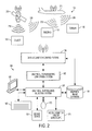
- Figure 2 shows the surveillance system 100 using a different set of data acquisition devices.
- the data acquisition devices are mobile aerial devices and include a satellite 205 and an aircraft 210 (or drone).
- Satellite 205 is configured to acquire surveillance data within field of view 215, which encompasses object 125, as well as data within field of view 220, which encompasses building 135.
- Aircraft 210 is configured to acquire surveillance data within field of view 225, which encompasses building 135, as well as within field of view 230, which encompasses terrain 145.
- both satellite 205 and aircraft 210 have overlapping fields of view which include building 135.
- Surveillance data for building 135 may be acquired by the satellite 205 and aircraft 210 concurrently or at different times. Additionally, or in the alternative, surveillance data for different views of the building 1135 may be acquired by the satellite 205 and aircraft 210.
- the surveillance data from the aircraft 210 may be transmitted in real time over a radio frequency communication link or transferred to the graphical image database 150 upon landing.
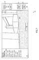
- FIGS 3-7 are various views showing the graphical manipulation of an image in three-dimensional space for selecting a target area that is to be subject to surveillance by one or more data acquisition devices.
- Each figure includes a screenshot 300 that may be shown on electronic display 165 pursuant to selecting the target area.
- the screenshot 300 includes an image portion 305 displaying an image of the selected surveillance area.
- the screenshot 300 may include an information portion 307 displaying various parameters associated with the selected surveillance area, and a surveillance request portion 309 including one or more activation buttons 311 for initiating the surveillance request.
- the surveillance request portion may also indicate a feedback area 313 indicating that the surveillance request has been initiated and providing an ETA at which the user can expect to receive the surveillance data.
- Figure 3 is an example showing one image that may be used to designate the area that is to be subject to surveillance. Images such as the one shown in Figure 3 may be obtained by aerial data acquisition devices on, for example, satellite 205 and/or aircraft 210. As shown, the selected surveillance image of Figure 3 includes streets, rivers, and a cluster of buildings 310.
- Figure 4 shows one manner in which the user may manipulate the selected surveillance image of Figure 3 to more particularly focus on the cluster of buildings 310.
- a field of view adjustment, an altitude adjustment, a lateral displacement, and a transverse displacement of the image of Figure 3 have been executed by the user in three-dimensional image space.
- the cluster of buildings 310 is now centrally located in the selected surveillance image of Figure 4 and the field of view has been adjusted to principally focus on the cluster of buildings 310.
- Figure 5 shows one manner in which the user may manipulate the selected surveillance image of Figure 4 in three-dimensional space to more particularly focus on elevated views of the cluster of buildings 310 for surveillance.
- an elevation adjustment, an azimuth adjustment, a field of view adjustment, an altitude adjustment, a lateral displacement, and a transverse displacement of the image of Figure 3 have been executed by the user in three-dimensional image space.
- the resulting selected surveillance image of Figure 5 principally includes a front view of building 310a with minimal portions of the sides of both buildings 310a and 310b.
- Figure 6 shows one manner in which the user may manipulate the selected surveillance image of Figure 5 in three-dimensional space to more particularly focus on elevated side views of the cluster of buildings 310 for surveillance.
- the transition to the selected surveillance image of Figure 6 further operations in response to user manipulation of the image of Figure 5 in three-dimensional space have been executed.
- the resulting selected surveillance image of Figure 6 principally includes a side view elevations of both building 310a with minimal portions of the front side of buildings 310a and 310b.
- Figure 7 shows one manner in which the user may manipulate the selected surveillance image of Figure 6 in three-dimensional space to more particularly focus on elevated side views of the cluster of buildings 310 for surveillance.
- the transition to the selected surveillance image of Figure 7 further operations in response to user manipulation of the image of Figure 6 in three-dimensional space have been executed.
- the resulting selected surveillance image of Figure 7 principally includes a side view elevation of building 310b.
- Transitional views of the selected surveillance image between an initial view and a final view may take place in a continuous manner.
- the transitions between the selected surveillance images shown in Figure 3 through Figure 7 are merely exemplary and do not represent a definitive sequence of graphical manipulations to arrive at a final selected surveillance image.
- a transition from the selected surveillance image of Figure 3 to any one of the selected surveillance images of Figure 4 through Figure 7 may be continuous. It will be recognized that other three-dimensional manipulations may be used to transition from an initial image to a final selected surveillance image.
Landscapes
- Engineering & Computer Science (AREA)
- General Engineering & Computer Science (AREA)
- Theoretical Computer Science (AREA)
- Signal Processing (AREA)
- Multimedia (AREA)
- Physics & Mathematics (AREA)
- General Physics & Mathematics (AREA)
- Software Systems (AREA)
- Computer Hardware Design (AREA)
- Computer Graphics (AREA)
- Human Computer Interaction (AREA)
- Closed-Circuit Television Systems (AREA)
- Alarm Systems (AREA)
Abstract
Description
- Surveillance systems are employed in a wide range of applications. Street corners may include image acquisition devices that are fixed to a stationary object to conduct surveillance of traffic and pedestrians. Similarly, buildings may employ image acquisition devices that are likewise fixed at stationary positions within the building to monitor activities of persons and objects.
- Surveillance systems are also used to acquire intelligence information for law enforcement and military organizations. Such surveillance systems are often used to acquire surveillance data from varying geographical locations as well as varying views of the geographic locations. The surveillance data may be acquired from fixed data acquisition devices and/or mobile data acquisition devices. However, the specific geographic information used to identify the area that is to be subject to surveillance is typically entered using type written entries of alphanumeric characters through a keyboard. Keyboard entry of this information is complicated since it requires the user to have a substantial amount of alphanumeric information corresponding to the area that is to be subject to surveillance information before it can be entered into the surveillance system.
- A surveillance system is disclosed that includes one or more data acquisition devices, an image database, and a processing system. The data acquisition devices are configured to acquire surveillance data from one or more geographic locations, and the image database stores image data for the one or more geographic locations. The processing system is configured to electronically display an image of one or more of the geographic locations using the image data stored in the image database. The processing system is further configured to accept input through a user interface to allow graphical manipulation of the displayed image in three-dimensional space to select a view of the geographical location that is to be subject to surveillance by the data acquisition devices. The displayed image selected by the user is employed to generate acquisition parameters for controlling the one or more data acquisition devices to surveil the geographical location corresponding to the displayed image.
- The features, functions, and advantages that have been discussed can be achieved independently in various embodiments or may be combined in yet other embodiments further details of which can be seen with reference to the following description and drawings.
-
-
Figure 1 is an illustration of a surveillance system that allows selection of an area that is to be subject to surveillance using three-dimensional graphical manipulation of an image. -
Figure 2 is an illustration of a further surveillance system that allows selection of an area that is to be subject to surveillance using three-dimensional graphical manipulation of an image. -
Figures 3 - 7 are various views of graphical manipulation of an image in three-dimensional space for selecting a target area that is to be subject to surveillance by one or more data acquisition devices. -
Figure 1 is an illustration of asurveillance system 100 that allows selection of an area that is to be subject to surveillance using three-dimensional graphical manipulation of an image. Thesurveillance system 100 includes a plurality ofdata acquisition devices view 120 that includesobject 125. Data acquisition device(s) 110 is configured to acquire surveillance data within field ofview 130 that includes building 135. Data acquisition device(s) 115 is configured to acquire surveillance data within field ofview 140 that includesterrain 145. One or more of the data acquisition devices may be configured so that their respective fields of view are varied in response to signals provided from other portions of thesurveillance system 100. - In this example, the
object 125,building 135, andterrain 145, may be at substantially different geographical locations where there is no overlap in the data acquisition areas. In such instances, the data acquisition device(s) 105 may be disposed at the geographic location that includesobject 125, data acquisition device(s) 110 may be disposed at the geographic location that includes building 135, and data acquisition device(s) 115 may be disposed at the geographic location that includesterrain 145. - The data acquisition device(s) may include a plurality of acquisition devices. The data acquisition devices may be configured to acquire various types of surveillance data. The various types of surveillance data may include: 1) visual image data; 2) infrared data; 3) radio frequency data; 4) magnetometer data (from a magnetometer sensor); 5) explosive material detection data (from an explosive materials detector); and/or 6) facial recognition detection data from, for example, locally executed facial recognition software. It will be recognized, however, that other types of surveillance data may be acquired by corresponding acquisition devices designed to acquire such other surveillance data types.
- The
surveillance system 100 also includes agraphical image database 150. The image database stores image data for one or more geographic locations. InFigure 1 , thegraphical image database 150 stores image data for the locations that includeobject 125,building 135, andterrain 145. The image data may be in the form of three-dimensional image data. - A
processing system 155 is configured to execute a number of different operations using a number of different processing components. In this example, theprocessing system 155 is configured to electronically display an image of one or more of the geographic locations using the image data stored in thegraphical image database 150. To this end, theprocessing system 155 includes a graphicalsurveillance selection system 160 that receives graphical image data from thegraphical image database 150 and displays the received image data onelectronic display 165. - The
processing system 155 is also configured to accept input through a user interface to allow graphical manipulation of the displayed image by a user. The graphical manipulation is in three-dimensional space and allows the user to graphically select an image corresponding to an area that is to be subject to surveillance by one or more of thedata acquisition devices electronic display 165. Additionally, or in the alternative, the manipulated image may be shown to the user on more than one display. When more than one display is used, the user may concurrently view separate surveillance areas. For example, a "before manipulation" image may be shown on one display and an "after manipulation" image on the other. The "after manipulation" image on one display may be transferred to replace the "before manipulation" image on the other display to hone selection of the surveillance area by allowing the user to concurrently utilize slightly different views of the overall target surveillance area during graphical manipulation. - The graphical
surveillance selection system 160 may receive user input from one or more user input devices to graphically manipulate the displayed image. Here, the graphicalsurveillance selection system 160 allows the user to manipulate the displayed image using, for example: 1) keys on a keyboard 167 (i.e., different keys providing different directions of movement through the image in three-dimensional space); 2) a mouse orother pointing device 170; 3) a touchscreen incorporated intoelectronic display 165; 4) an accelerometer and/or gyroscope 175 (i.e., a virtual reality input device); and/or 5) amobile device 180. In one example, at least the graphicalsurveillance selection system 160 and theelectronic display 165 may be integrated into a single mobile device. - The
processing system 155 uses the graphically selected view of the displayed image to generate acquisition parameters for controlling one or more of the data acquisition devices. InFigure 1 , the graphicalsurveillance selection system 160 communicates data corresponding to the graphically selected view of the displayed image to a graphical-to-parametric conversion system 185. The graphical-to-parametric conversion system 185 uses this data to generate parameters employed to ultimately control one or more of thedata acquisition devices - The parametric data generated by the graphical-to-
parametric conversion system 185 may be provided to a dataacquisition control system 190. The dataacquisition control system 190, in turn, uses the parametric data to control the data acquisition devices by communicating either the parametric data or control data derived from the parametric data to the data acquisition devices. To this end, the dataacquisition control system 190 is configured for communication with each of the data acquisition devices. Such communication may be by means of: 1) a wireless network; 2) the Internet or other wide area network; and/or 3) radio frequency communication links. Other means for communication may also be employed. - A substantial number of data acquisition parameter types may be generated through the three-dimensional graphical manipulation. For example, the parameters may include: 1) latitude parameters; 2) longitude parameters; 3) altitude parameters; 4) azimuth parameters; 5) elevation parameters; 6) zoom parameters; and/or 7) field of view parameters. The user may also manually select the type of sensor (i.e. visual image sensor, infrared sensor, etc.) that is to be used for the surveillance. Additionally, or on the alternative, the user may select the type of data that is to be acquired (i.e., visual image data, infrared data, etc.) The graphical-to-
parametric conversion system 185 and/or the dataacquisition control system 190 may select the appropriate sensor type based on the input of the user. - Other parameters that may input by the user relate to time. For example, the user may input the start and end time during which surveillance data is to be acquired, the start and duration during which surveillance data is to be acquired, etc.
- Surveillance data is received from the data acquisition devices by the data
acquisition control system 190. The acquired surveillance data corresponding to the selected surveillance area may be attached as metadata to an image corresponding to the selected surveillance area. The newly acquired surveillance data may then be reviewed by the user using the graphicalsurveillance selection system 160 to display the surveillance area onelectronic display 165 along with the corresponding new image and/or metadata for the surveillance area as provided by thegraphical image database 150. - The
graphical image database 150 may include initial graphic information for various surveillance areas. This initial graphic information may or may not include images that have been updated with the latest acquired image surveillance data. When the acquired surveillance data is visual image data, the visual image data may be used to update the portions of thegraphical image database 150 associated with the selected surveillance area so that the user manipulates the latest visual image of the area. -
Figure 2 shows thesurveillance system 100 using a different set of data acquisition devices. Here, the data acquisition devices are mobile aerial devices and include asatellite 205 and an aircraft 210 (or drone).Satellite 205 is configured to acquire surveillance data within field ofview 215, which encompassesobject 125, as well as data within field ofview 220, which encompassesbuilding 135.Aircraft 210 is configured to acquire surveillance data within field ofview 225, which encompasses building 135, as well as within field ofview 230, which encompassesterrain 145. In this example, therefore, bothsatellite 205 andaircraft 210 have overlapping fields of view which includebuilding 135. Surveillance data for building 135 may be acquired by thesatellite 205 andaircraft 210 concurrently or at different times. Additionally, or in the alternative, surveillance data for different views of the building 1135 may be acquired by thesatellite 205 andaircraft 210. The surveillance data from theaircraft 210 may be transmitted in real time over a radio frequency communication link or transferred to thegraphical image database 150 upon landing. -
Figures 3-7 are various views showing the graphical manipulation of an image in three-dimensional space for selecting a target area that is to be subject to surveillance by one or more data acquisition devices. Each figure includes ascreenshot 300 that may be shown onelectronic display 165 pursuant to selecting the target area. Thescreenshot 300 includes animage portion 305 displaying an image of the selected surveillance area. Optionally, thescreenshot 300 may include aninformation portion 307 displaying various parameters associated with the selected surveillance area, and asurveillance request portion 309 including one ormore activation buttons 311 for initiating the surveillance request. The surveillance request portion may also indicate afeedback area 313 indicating that the surveillance request has been initiated and providing an ETA at which the user can expect to receive the surveillance data. In these examples, all the values of the parameters ininformation portion 307 are designated with the variable "XXXX." However, it will be recognized that the value of these variables change as the user manipulates theimage portion 305 in three-dimensional space. Also, more or fewer parameters may be used and/or displayed depending on system requirements. -
Figure 3 is an example showing one image that may be used to designate the area that is to be subject to surveillance. Images such as the one shown inFigure 3 may be obtained by aerial data acquisition devices on, for example,satellite 205 and/oraircraft 210. As shown, the selected surveillance image ofFigure 3 includes streets, rivers, and a cluster ofbuildings 310. -
Figure 4 shows one manner in which the user may manipulate the selected surveillance image ofFigure 3 to more particularly focus on the cluster ofbuildings 310. In the transition to the selected surveillance image ofFigure 4 , a field of view adjustment, an altitude adjustment, a lateral displacement, and a transverse displacement of the image ofFigure 3 have been executed by the user in three-dimensional image space. The cluster ofbuildings 310 is now centrally located in the selected surveillance image ofFigure 4 and the field of view has been adjusted to principally focus on the cluster ofbuildings 310. -
Figure 5 shows one manner in which the user may manipulate the selected surveillance image ofFigure 4 in three-dimensional space to more particularly focus on elevated views of the cluster ofbuildings 310 for surveillance. In the transition to the selected surveillance image ofFigure 5 , an elevation adjustment, an azimuth adjustment, a field of view adjustment, an altitude adjustment, a lateral displacement, and a transverse displacement of the image ofFigure 3 have been executed by the user in three-dimensional image space. The resulting selected surveillance image ofFigure 5 principally includes a front view ofbuilding 310a with minimal portions of the sides of bothbuildings -
Figure 6 shows one manner in which the user may manipulate the selected surveillance image ofFigure 5 in three-dimensional space to more particularly focus on elevated side views of the cluster ofbuildings 310 for surveillance. In the transition to the selected surveillance image ofFigure 6 further operations in response to user manipulation of the image ofFigure 5 in three-dimensional space have been executed. The resulting selected surveillance image ofFigure 6 principally includes a side view elevations of bothbuilding 310a with minimal portions of the front side ofbuildings -
Figure 7 shows one manner in which the user may manipulate the selected surveillance image ofFigure 6 in three-dimensional space to more particularly focus on elevated side views of the cluster ofbuildings 310 for surveillance. In the transition to the selected surveillance image ofFigure 7 further operations in response to user manipulation of the image ofFigure 6 in three-dimensional space have been executed. The resulting selected surveillance image ofFigure 7 principally includes a side view elevation ofbuilding 310b. - Transitional views of the selected surveillance image between an initial view and a final view may take place in a continuous manner. To this end, the transitions between the selected surveillance images shown in
Figure 3 through Figure 7 are merely exemplary and do not represent a definitive sequence of graphical manipulations to arrive at a final selected surveillance image. For example, a transition from the selected surveillance image ofFigure 3 to any one of the selected surveillance images ofFigure 4 through Figure 7 may be continuous. It will be recognized that other three-dimensional manipulations may be used to transition from an initial image to a final selected surveillance image. - Further, the disclosure comprises embodiments according to the following clauses:
- Clause 1. A surveillance system comprising:
- one or more data acquisition devices configured to acquire surveillance data from one or more geographic locations;
- an image database storing image data for the one or more geographic locations; and
- a processing system configured to:
- electronically display an image of one or more of the geographic locations using the image data stored in the image database;
- accept input through a user interface to allow graphical manipulation of the displayed image by a user, wherein the graphical manipulation is in three-dimensional space, and wherein the graphical manipulation allows the user to graphically select a view of the one or more geographic locations that is to be subject to surveillance by the one or more data acquisition devices; and
- use the graphically selected view of the displayed image to generate acquisition parameters for controlling the one or more data acquisition devices.
- Clause 2. The surveillance system of clause 1, wherein the electronically displayed image of the one or more geographic locations and the user interface are incorporated into a mobile device.
- Clause 3. The surveillance system of clause 1, wherein at least one of the data acquisition devices is an image acquisition device.
- Clause 4. The surveillance system of clause 1, wherein the one or more data acquisition devices comprise a plurality of image acquisition devices.
- Clause 5. The surveillance system of clause 1, wherein the one or more data acquisition devices are disposed at a plurality of separate geographic locations.
- Clause 6. The surveillance system of clause 1, wherein the plurality of data acquisition devices are disposed to monitor a single geographic location.
- Clause 7. The surveillance system of clause 1, wherein the one or more data acquisition devices comprise at least one of an infrared sensor and/or a magnetometer sensor.
- Clause 8. The surveillance system of clause 1, wherein the acquisition parameters include field of view parameters.
- Clause 9. The surveillance system of clause 1, wherein the acquisition parameters include an elevation parameter and an azimuth parameter.
- Clause 10. The surveillance system of clause 1, wherein the acquisition parameters include a latitude parameter, a longitude parameter, and an altitude parameter.
- Clause 11. The surveillance system of clause 1, wherein the acquisition parameters include a time parameter.
- Clause 12. The surveillance system of clause 1, wherein the acquisition parameters include a sensor type parameter.
- Clause 13. The surveillance system of clause 1, wherein the user interface comprises one or more of a pointing device, a keyboard, a touchscreen, a mobile device, an accelerometer, or gyroscope.
- Clause 14. The surveillance system of clause 1, further comprising a data acquisition control system configured to transmit control data to the one or more acquisition devices based on the acquisition parameters.
- Clause 15. The surveillance system of clause 10, further comprising a data acquisition control system configured to receive the surveillance data from the one or more data acquisition devices for display to the user.
- Clause 16. The surveillance system of clause 11, wherein the surveillance data comprises image data, and wherein the surveillance system further comprises a database update system configured to update the image data stored in the image database.
- Clause 17. The surveillance system of clause 1, wherein the one or more acquisition devices include an explosive materials detector.
- Clause 18. The surveillance system of clause 1, wherein the one or more acquisition devices include locally executed facial recognition software.
- Clause 19. A surveillance system comprising:
- an image database storing image data for one or more geographic locations that may be subject to surveillance;
- a graphical surveillance selection system configured to allow a user to manipulate a displayed image obtained from the image database in three-dimensional space to designate a view of the one or more geographic locations that is to be subject to surveillance by one or more data acquisition devices; and
- a graphical-to-parametric conversion system configured to receive data corresponding to the designated view of the one or more geographical locations that is to be subject to surveillance from the graphical surveillance selection system, wherein the graphical-to-parametric conversion system converts the received data to acquisition parameters employed to control the one or more data acquisition devices.
- Clause 20. The surveillance system of clause 19, further comprising a data acquisition control system configured to use the acquisition parameters to control the one or more data acquisition devices and to receive surveillance data from the one or more data acquisition devices.
- Clause 21. The surveillance system of clause 20, wherein the data acquisition control system communicates acquisition parameters and/or control signals corresponding to the acquisition parameters to the one or more data acquisition devices.
- Clause 22. The surveillance system of clause 19, wherein the graphical surveillance selection system is incorporated into a mobile device.
- Clause 23. The surveillance system of clause 19, wherein the acquisition parameters include an azimuth parameter and elevation parameter.
- Clause 24. The surveillance system of clause 19, wherein the acquisition parameters include a latitude parameter, longitude parameter, and an altitude parameter.
- Clause 25. The surveillance system of clause 19, wherein the acquisition parameters include a time parameter.
- Clause 26. The surveillance system of clause 19, wherein the plurality of data acquisition devices are disposed to monitor a single geographic location.
- Clause 27. The surveillance system of clause 19, wherein the one or more data acquisition devices comprise at least one of an infrared sensor and/or a magnetometer sensor.
- Clause 28. The surveillance system of clause 19, wherein the acquisition parameters include field of view parameters.
- Clause 29. A method of conducting surveillance comprising:
- electronically displaying an image of one or more geographic locations associated with one or more data acquisition devices, wherein the displayed image is generated using three-dimensional image data stored in an image database;
- accepting user input to graphically manipulate the displayed image in three-dimensional space to select a view of the displayed image corresponding to the one or more geographic locations that are to be subject to surveillance; and
- using the selected view of the displayed image to generate acquisition parameters for controlling the one or more image acquisition devices.
- Clause 30. The method of surveillance of clause 29, wherein the generated acquisition parameters include a parameter selected from the group of a latitude parameter, a longitude parameter, an elevation parameter, an altitude parameter, an azimuth parameter, a field of view parameter, a zoom parameter, a time parameter, and a sensor type parameter.
Claims (15)
- A surveillance system (100) comprising:one or more data acquisition devices (105, 110, 115) configured to acquire surveillance data from one or more geographic locations;an image database (150) storing image data for the one or more geographic locations; anda processing system (155) configured to:electronically display an image of one or more of the geographic locations using the image data stored in the image database (150);accept input through a user interface to allow graphical manipulation of the displayed image by a user, wherein the graphical manipulation is in three-dimensional space, and wherein the graphical manipulation allows the user to graphically select a view of the one or more geographic locations that is to be subject to surveillance by the one or more data acquisition devices (105, 110, 115); anduse the graphically selected view of the displayed image to generate acquisition parameters for controlling the one or more data acquisition devices (105, 110, 115).
- The surveillance system of claim 1, wherein the electronically displayed image of the one or more geographic locations and the user interface are incorporated into a mobile device (180).
- The surveillance system of claim 1 or 2, wherein at least one of the data acquisition devices (105, 110, 115) is an image acquisition device.
- The surveillance system of any of claims 1 to 3, wherein the one or more data acquisition devices (105, 110, 115) are disposed at a plurality of separate geographic locations.
- The surveillance system of any of claims 1 to 4, wherein the one or more data acquisition devices (105, 110, 115) comprise at least one of an infrared sensor and/or a magnetometer sensor.
- The surveillance system of any of claims 1 to 5, wherein the acquisition parameters include field of view parameters.
- The surveillance system of any of claims 1 to 6, wherein the acquisition parameters include an elevation parameter and an azimuth parameter.
- The surveillance system of any of claims 1 to 7, wherein the acquisition parameters include a latitude parameter, a longitude parameter, and an altitude parameter.
- The surveillance system of any of claims 1 to 8, wherein the acquisition parameters include a time parameter.
- The surveillance system of any of claims 1 to 9, wherein the acquisition parameters include a sensor type parameter.
- The surveillance system of any of claims 1 to 10, further comprising a data acquisition control system (190) configured to transmit control data to the one or more acquisition devices (105, 110, 115) based on the acquisition parameters.
- The surveillance system of any of claims 1 to 11, wherein the one or more acquisition devices (105, 110, 115) include an explosive materials detector.
- The surveillance system of any of claims 1 to 12, wherein the one or more acquisition devices (105, 110, 115) include locally executed facial recognition software.
- A method of conducting surveillance comprising:electronically displaying an image of one or more geographic locations associated with one or more data acquisition devices (105, 110, 115), wherein the displayed image is generated using three-dimensional image data stored in an image database (150);accepting user input to graphically manipulate the displayed image in three-dimensional space to select a view of the displayed image corresponding to the one or more geographic locations that are to be subject to surveillance; andusing the selected view of the displayed image to generate acquisition parameters for controlling the one or more image acquisition devices (105, 110, 115).
- The method of surveillance of claim 14, wherein the generated acquisition parameters include a parameter selected from the group of a latitude parameter, a longitude parameter, an elevation parameter, an altitude parameter, an azimuth parameter, a field of view parameter, a zoom parameter, a time parameter, and a sensor type parameter.
Applications Claiming Priority (1)
| Application Number | Priority Date | Filing Date | Title |
|---|---|---|---|
| US14/038,100 US9860489B2 (en) | 2013-09-26 | 2013-09-26 | System and method for graphically entering views of terrain and other features for surveillance |
Publications (2)
| Publication Number | Publication Date |
|---|---|
| EP2854115A1 true EP2854115A1 (en) | 2015-04-01 |
| EP2854115B1 EP2854115B1 (en) | 2018-08-08 |
Family
ID=51535333
Family Applications (1)
| Application Number | Title | Priority Date | Filing Date |
|---|---|---|---|
| EP14183868.0A Active EP2854115B1 (en) | 2013-09-26 | 2014-09-08 | System and method for graphically entering views of terrain and other features for surveillance |
Country Status (2)
| Country | Link |
|---|---|
| US (1) | US9860489B2 (en) |
| EP (1) | EP2854115B1 (en) |
Family Cites Families (5)
| Publication number | Priority date | Publication date | Assignee | Title |
|---|---|---|---|---|
| US7131136B2 (en) * | 2002-07-10 | 2006-10-31 | E-Watch, Inc. | Comprehensive multi-media surveillance and response system for aircraft, operations centers, airports and other commercial transports, centers and terminals |
| KR20050000276A (en) * | 2003-06-24 | 2005-01-03 | 주식회사 성진씨앤씨 | Virtual joystick system for controlling the operation of a security camera and controlling method thereof |
| US20100013917A1 (en) * | 2003-08-12 | 2010-01-21 | Keith Hanna | Method and system for performing surveillance |
| WO2012037157A2 (en) * | 2010-09-13 | 2012-03-22 | Alt Software (Us) Llc | System and method for displaying data having spatial coordinates |
| MY171846A (en) * | 2010-12-27 | 2019-11-04 | Mimos Berhad | System and method for navigation and visualization |
-
2013
- 2013-09-26 US US14/038,100 patent/US9860489B2/en active Active
-
2014
- 2014-09-08 EP EP14183868.0A patent/EP2854115B1/en active Active
Non-Patent Citations (3)
| Title |
|---|
| BOYD J E ET AL: "MPI-Video infrastructure for dynamic environments", MULTIMEDIA COMPUTING AND SYSTEMS, 1998. PROCEEDINGS. IEEE INTERNATIONA L CONFERENCE ON AUSTIN, TX, USA 28 JUNE-1 JULY 1998, LOS ALAMITOS, CA, USA,IEEE COMPUT. SOC, US, 28 June 1998 (1998-06-28), pages 249 - 254, XP010291550, ISBN: 978-0-8186-8557-6, DOI: 10.1109/MMCS.1998.693651 * |
| JAIN R ET AL: "Multiple perspective interactive video", PROCEEDINGS OF THE INTERNATIONAL CONFERENCE ON MULTIMEDIA COMPUTING AND SYSTEMS. WASHINGTON, MAY 15 - 18, 1995; [PROCEEDINGS OF THE INTERNATIONAL CONFERENCE ON MULTIMEDIA COMPUTING AND SYSTEMS], LOS ALAMITOS, IEEE COMP. SOC. PRESS, US, 15 May 1995 (1995-05-15), pages 202 - 211, XP010154598, ISBN: 978-0-8186-7105-0, DOI: 10.1109/MMCS.1995.484925 * |
| KATKERE A ET AL: "VRML-BASED WWW INTERFACE TO MPI VIDEO", SYMPOSIUM ON THE VIRTUAL REALITY MODELING LANGUAGE. PROCEEDINGSOF VMRL WORKSHOP, XX, XX, 14 December 1995 (1995-12-14), pages 25 - 31, XP000791035, DOI: 10.1145/217306.217310 * |
Also Published As
| Publication number | Publication date |
|---|---|
| EP2854115B1 (en) | 2018-08-08 |
| US20150085112A1 (en) | 2015-03-26 |
| US9860489B2 (en) | 2018-01-02 |
Similar Documents
| Publication | Publication Date | Title |
|---|---|---|
| US20230298473A1 (en) | Interactive and customizable flight planning tool | |
| US20250003758A1 (en) | Methods and systems for response vehicle deployment | |
| US11176833B1 (en) | Flight management system and flight plan alert integration systems and methods | |
| JP2014040231A (en) | Autonomous airspace flight planning and virtual airspace containment system | |
| US9269239B1 (en) | Situational awareness system and method | |
| CN105644798B (en) | System and method for assisting pilots in locating out-of-view landing sites | |
| US20110216059A1 (en) | Systems and methods for generating real-time three-dimensional graphics in an area of interest | |
| US20100001902A1 (en) | Situation awareness display | |
| EP3407331A2 (en) | System & method for customizing a search and rescue pattern for an aircraft | |
| US10123181B1 (en) | Systems and methods for collaborative vehicle mission operations | |
| KR101076240B1 (en) | Apparatus and method for providing air defense battlefield using augmented reality | |
| KR20210012511A (en) | System for creating flight path and operating flight of unmanned aerianl vehicle | |
| US9860489B2 (en) | System and method for graphically entering views of terrain and other features for surveillance | |
| US20250168499A1 (en) | Observation assistance apparatus, observation assistance method, and computer-readable recording medium | |
| AU2010248083B2 (en) | Navigational display for parachutists | |
| KR20220170742A (en) | Control systems and control methods to check the movement status | |
| US20170140657A1 (en) | Augmented reality to display flight data and locate and control an aerial vehicle in real time | |
| KR102914941B1 (en) | Safe homecoming service system and method using drone | |
| Vaquero-Melchor et al. | Holo-mis: a mixed reality based drone mission definition system | |
| Brenner et al. | Exploring multi-attribute decision making for collaborative first-aid drone deliveries | |
| WO2021028408A1 (en) | Method and system for locating flying objects | |
| CN118963885A (en) | Method for generating configuration information of marking points, electronic device and storage medium | |
| US20210019545A1 (en) | Method and system to display object locations during a search and rescue operation |
Legal Events
| Date | Code | Title | Description |
|---|---|---|---|
| PUAI | Public reference made under article 153(3) epc to a published international application that has entered the european phase |
Free format text: ORIGINAL CODE: 0009012 |
|
| 17P | Request for examination filed |
Effective date: 20140908 |
|
| AK | Designated contracting states |
Kind code of ref document: A1 Designated state(s): AL AT BE BG CH CY CZ DE DK EE ES FI FR GB GR HR HU IE IS IT LI LT LU LV MC MK MT NL NO PL PT RO RS SE SI SK SM TR |
|
| AX | Request for extension of the european patent |
Extension state: BA ME |
|
| R17P | Request for examination filed (corrected) |
Effective date: 20150929 |
|
| RBV | Designated contracting states (corrected) |
Designated state(s): AL AT BE BG CH CY CZ DE DK EE ES FI FR GB GR HR HU IE IS IT LI LT LU LV MC MK MT NL NO PL PT RO RS SE SI SK SM TR |
|
| 17Q | First examination report despatched |
Effective date: 20161214 |
|
| GRAP | Despatch of communication of intention to grant a patent |
Free format text: ORIGINAL CODE: EPIDOSNIGR1 |
|
| INTG | Intention to grant announced |
Effective date: 20180220 |
|
| GRAS | Grant fee paid |
Free format text: ORIGINAL CODE: EPIDOSNIGR3 |
|
| GRAA | (expected) grant |
Free format text: ORIGINAL CODE: 0009210 |
|
| AK | Designated contracting states |
Kind code of ref document: B1 Designated state(s): AL AT BE BG CH CY CZ DE DK EE ES FI FR GB GR HR HU IE IS IT LI LT LU LV MC MK MT NL NO PL PT RO RS SE SI SK SM TR |
|
| REG | Reference to a national code |
Ref country code: GB Ref legal event code: FG4D |
|
| REG | Reference to a national code |
Ref country code: CH Ref legal event code: EP Ref country code: AT Ref legal event code: REF Ref document number: 1027903 Country of ref document: AT Kind code of ref document: T Effective date: 20180815 |
|
| REG | Reference to a national code |
Ref country code: IE Ref legal event code: FG4D |
|
| REG | Reference to a national code |
Ref country code: DE Ref legal event code: R096 Ref document number: 602014029849 Country of ref document: DE |
|
| REG | Reference to a national code |
Ref country code: FR Ref legal event code: PLFP Year of fee payment: 5 |
|
| REG | Reference to a national code |
Ref country code: NL Ref legal event code: MP Effective date: 20180808 |
|
| REG | Reference to a national code |
Ref country code: LT Ref legal event code: MG4D |
|
| REG | Reference to a national code |
Ref country code: AT Ref legal event code: MK05 Ref document number: 1027903 Country of ref document: AT Kind code of ref document: T Effective date: 20180808 |
|
| PG25 | Lapsed in a contracting state [announced via postgrant information from national office to epo] |
Ref country code: GR Free format text: LAPSE BECAUSE OF FAILURE TO SUBMIT A TRANSLATION OF THE DESCRIPTION OR TO PAY THE FEE WITHIN THE PRESCRIBED TIME-LIMIT Effective date: 20181109 Ref country code: NO Free format text: LAPSE BECAUSE OF FAILURE TO SUBMIT A TRANSLATION OF THE DESCRIPTION OR TO PAY THE FEE WITHIN THE PRESCRIBED TIME-LIMIT Effective date: 20181108 Ref country code: AT Free format text: LAPSE BECAUSE OF FAILURE TO SUBMIT A TRANSLATION OF THE DESCRIPTION OR TO PAY THE FEE WITHIN THE PRESCRIBED TIME-LIMIT Effective date: 20180808 Ref country code: LT Free format text: LAPSE BECAUSE OF FAILURE TO SUBMIT A TRANSLATION OF THE DESCRIPTION OR TO PAY THE FEE WITHIN THE PRESCRIBED TIME-LIMIT Effective date: 20180808 Ref country code: BG Free format text: LAPSE BECAUSE OF FAILURE TO SUBMIT A TRANSLATION OF THE DESCRIPTION OR TO PAY THE FEE WITHIN THE PRESCRIBED TIME-LIMIT Effective date: 20181108 Ref country code: NL Free format text: LAPSE BECAUSE OF FAILURE TO SUBMIT A TRANSLATION OF THE DESCRIPTION OR TO PAY THE FEE WITHIN THE PRESCRIBED TIME-LIMIT Effective date: 20180808 Ref country code: PL Free format text: LAPSE BECAUSE OF FAILURE TO SUBMIT A TRANSLATION OF THE DESCRIPTION OR TO PAY THE FEE WITHIN THE PRESCRIBED TIME-LIMIT Effective date: 20180808 Ref country code: IS Free format text: LAPSE BECAUSE OF FAILURE TO SUBMIT A TRANSLATION OF THE DESCRIPTION OR TO PAY THE FEE WITHIN THE PRESCRIBED TIME-LIMIT Effective date: 20181208 Ref country code: SE Free format text: LAPSE BECAUSE OF FAILURE TO SUBMIT A TRANSLATION OF THE DESCRIPTION OR TO PAY THE FEE WITHIN THE PRESCRIBED TIME-LIMIT Effective date: 20180808 Ref country code: RS Free format text: LAPSE BECAUSE OF FAILURE TO SUBMIT A TRANSLATION OF THE DESCRIPTION OR TO PAY THE FEE WITHIN THE PRESCRIBED TIME-LIMIT Effective date: 20180808 Ref country code: FI Free format text: LAPSE BECAUSE OF FAILURE TO SUBMIT A TRANSLATION OF THE DESCRIPTION OR TO PAY THE FEE WITHIN THE PRESCRIBED TIME-LIMIT Effective date: 20180808 |
|
| PG25 | Lapsed in a contracting state [announced via postgrant information from national office to epo] |
Ref country code: AL Free format text: LAPSE BECAUSE OF FAILURE TO SUBMIT A TRANSLATION OF THE DESCRIPTION OR TO PAY THE FEE WITHIN THE PRESCRIBED TIME-LIMIT Effective date: 20180808 Ref country code: LV Free format text: LAPSE BECAUSE OF FAILURE TO SUBMIT A TRANSLATION OF THE DESCRIPTION OR TO PAY THE FEE WITHIN THE PRESCRIBED TIME-LIMIT Effective date: 20180808 Ref country code: HR Free format text: LAPSE BECAUSE OF FAILURE TO SUBMIT A TRANSLATION OF THE DESCRIPTION OR TO PAY THE FEE WITHIN THE PRESCRIBED TIME-LIMIT Effective date: 20180808 |
|
| PG25 | Lapsed in a contracting state [announced via postgrant information from national office to epo] |
Ref country code: EE Free format text: LAPSE BECAUSE OF FAILURE TO SUBMIT A TRANSLATION OF THE DESCRIPTION OR TO PAY THE FEE WITHIN THE PRESCRIBED TIME-LIMIT Effective date: 20180808 Ref country code: IT Free format text: LAPSE BECAUSE OF FAILURE TO SUBMIT A TRANSLATION OF THE DESCRIPTION OR TO PAY THE FEE WITHIN THE PRESCRIBED TIME-LIMIT Effective date: 20180808 Ref country code: RO Free format text: LAPSE BECAUSE OF FAILURE TO SUBMIT A TRANSLATION OF THE DESCRIPTION OR TO PAY THE FEE WITHIN THE PRESCRIBED TIME-LIMIT Effective date: 20180808 Ref country code: CZ Free format text: LAPSE BECAUSE OF FAILURE TO SUBMIT A TRANSLATION OF THE DESCRIPTION OR TO PAY THE FEE WITHIN THE PRESCRIBED TIME-LIMIT Effective date: 20180808 Ref country code: ES Free format text: LAPSE BECAUSE OF FAILURE TO SUBMIT A TRANSLATION OF THE DESCRIPTION OR TO PAY THE FEE WITHIN THE PRESCRIBED TIME-LIMIT Effective date: 20180808 |
|
| REG | Reference to a national code |
Ref country code: CH Ref legal event code: PL |
|
| REG | Reference to a national code |
Ref country code: DE Ref legal event code: R097 Ref document number: 602014029849 Country of ref document: DE |
|
| PG25 | Lapsed in a contracting state [announced via postgrant information from national office to epo] |
Ref country code: SK Free format text: LAPSE BECAUSE OF FAILURE TO SUBMIT A TRANSLATION OF THE DESCRIPTION OR TO PAY THE FEE WITHIN THE PRESCRIBED TIME-LIMIT Effective date: 20180808 Ref country code: SM Free format text: LAPSE BECAUSE OF FAILURE TO SUBMIT A TRANSLATION OF THE DESCRIPTION OR TO PAY THE FEE WITHIN THE PRESCRIBED TIME-LIMIT Effective date: 20180808 Ref country code: DK Free format text: LAPSE BECAUSE OF FAILURE TO SUBMIT A TRANSLATION OF THE DESCRIPTION OR TO PAY THE FEE WITHIN THE PRESCRIBED TIME-LIMIT Effective date: 20180808 |
|
| REG | Reference to a national code |
Ref country code: BE Ref legal event code: MM Effective date: 20180930 |
|
| PLBE | No opposition filed within time limit |
Free format text: ORIGINAL CODE: 0009261 |
|
| STAA | Information on the status of an ep patent application or granted ep patent |
Free format text: STATUS: NO OPPOSITION FILED WITHIN TIME LIMIT |
|
| REG | Reference to a national code |
Ref country code: IE Ref legal event code: MM4A |
|
| PG25 | Lapsed in a contracting state [announced via postgrant information from national office to epo] |
Ref country code: MC Free format text: LAPSE BECAUSE OF FAILURE TO SUBMIT A TRANSLATION OF THE DESCRIPTION OR TO PAY THE FEE WITHIN THE PRESCRIBED TIME-LIMIT Effective date: 20180808 Ref country code: LU Free format text: LAPSE BECAUSE OF NON-PAYMENT OF DUE FEES Effective date: 20180908 |
|
| 26N | No opposition filed |
Effective date: 20190509 |
|
| PG25 | Lapsed in a contracting state [announced via postgrant information from national office to epo] |
Ref country code: IE Free format text: LAPSE BECAUSE OF NON-PAYMENT OF DUE FEES Effective date: 20180908 |
|
| PG25 | Lapsed in a contracting state [announced via postgrant information from national office to epo] |
Ref country code: BE Free format text: LAPSE BECAUSE OF NON-PAYMENT OF DUE FEES Effective date: 20180930 Ref country code: CH Free format text: LAPSE BECAUSE OF NON-PAYMENT OF DUE FEES Effective date: 20180930 Ref country code: LI Free format text: LAPSE BECAUSE OF NON-PAYMENT OF DUE FEES Effective date: 20180930 Ref country code: SI Free format text: LAPSE BECAUSE OF FAILURE TO SUBMIT A TRANSLATION OF THE DESCRIPTION OR TO PAY THE FEE WITHIN THE PRESCRIBED TIME-LIMIT Effective date: 20180808 |
|
| PG25 | Lapsed in a contracting state [announced via postgrant information from national office to epo] |
Ref country code: MT Free format text: LAPSE BECAUSE OF NON-PAYMENT OF DUE FEES Effective date: 20180908 |
|
| PG25 | Lapsed in a contracting state [announced via postgrant information from national office to epo] |
Ref country code: TR Free format text: LAPSE BECAUSE OF FAILURE TO SUBMIT A TRANSLATION OF THE DESCRIPTION OR TO PAY THE FEE WITHIN THE PRESCRIBED TIME-LIMIT Effective date: 20180808 |
|
| PG25 | Lapsed in a contracting state [announced via postgrant information from national office to epo] |
Ref country code: HU Free format text: LAPSE BECAUSE OF FAILURE TO SUBMIT A TRANSLATION OF THE DESCRIPTION OR TO PAY THE FEE WITHIN THE PRESCRIBED TIME-LIMIT; INVALID AB INITIO Effective date: 20140908 Ref country code: PT Free format text: LAPSE BECAUSE OF FAILURE TO SUBMIT A TRANSLATION OF THE DESCRIPTION OR TO PAY THE FEE WITHIN THE PRESCRIBED TIME-LIMIT Effective date: 20180808 |
|
| PG25 | Lapsed in a contracting state [announced via postgrant information from national office to epo] |
Ref country code: CY Free format text: LAPSE BECAUSE OF FAILURE TO SUBMIT A TRANSLATION OF THE DESCRIPTION OR TO PAY THE FEE WITHIN THE PRESCRIBED TIME-LIMIT Effective date: 20180808 Ref country code: MK Free format text: LAPSE BECAUSE OF NON-PAYMENT OF DUE FEES Effective date: 20180808 |
|
| P01 | Opt-out of the competence of the unified patent court (upc) registered |
Effective date: 20230516 |
|
| PGFP | Annual fee paid to national office [announced via postgrant information from national office to epo] |
Ref country code: DE Payment date: 20250929 Year of fee payment: 12 |
|
| PGFP | Annual fee paid to national office [announced via postgrant information from national office to epo] |
Ref country code: GB Payment date: 20250929 Year of fee payment: 12 |
|
| PGFP | Annual fee paid to national office [announced via postgrant information from national office to epo] |
Ref country code: FR Payment date: 20250925 Year of fee payment: 12 |