EP2853756A1 - System and method of monitoring wear in a bearing - Google Patents
System and method of monitoring wear in a bearing Download PDFInfo
- Publication number
- EP2853756A1 EP2853756A1 EP14150078.5A EP14150078A EP2853756A1 EP 2853756 A1 EP2853756 A1 EP 2853756A1 EP 14150078 A EP14150078 A EP 14150078A EP 2853756 A1 EP2853756 A1 EP 2853756A1
- Authority
- EP
- European Patent Office
- Prior art keywords
- wafer
- liner
- bearing
- race
- lead
- Prior art date
- Legal status (The legal status is an assumption and is not a legal conclusion. Google has not performed a legal analysis and makes no representation as to the accuracy of the status listed.)
- Granted
Links
Images


Classifications
-
- F—MECHANICAL ENGINEERING; LIGHTING; HEATING; WEAPONS; BLASTING
- F16—ENGINEERING ELEMENTS AND UNITS; GENERAL MEASURES FOR PRODUCING AND MAINTAINING EFFECTIVE FUNCTIONING OF MACHINES OR INSTALLATIONS; THERMAL INSULATION IN GENERAL
- F16C—SHAFTS; FLEXIBLE SHAFTS; ELEMENTS OR CRANKSHAFT MECHANISMS; ROTARY BODIES OTHER THAN GEARING ELEMENTS; BEARINGS
- F16C17/00—Sliding-contact bearings for exclusively rotary movement
- F16C17/12—Sliding-contact bearings for exclusively rotary movement characterised by features not related to the direction of the load
- F16C17/24—Sliding-contact bearings for exclusively rotary movement characterised by features not related to the direction of the load with devices affected by abnormal or undesired positions, e.g. for preventing overheating, for safety
- F16C17/246—Sliding-contact bearings for exclusively rotary movement characterised by features not related to the direction of the load with devices affected by abnormal or undesired positions, e.g. for preventing overheating, for safety related to wear, e.g. sensors for measuring wear
-
- B—PERFORMING OPERATIONS; TRANSPORTING
- B60—VEHICLES IN GENERAL
- B60B—VEHICLE WHEELS; CASTORS; AXLES FOR WHEELS OR CASTORS; INCREASING WHEEL ADHESION
- B60B7/00—Wheel cover discs, rings, or the like, for ornamenting, protecting, venting, or obscuring, wholly or in part, the wheel body, rim, hub, or tyre sidewall, e.g. wheel cover discs, wheel cover discs with cooling fins
- B60B7/06—Fastening arrangements therefor
- B60B7/08—Fastening arrangements therefor having gripping elements consisting of formations integral with the cover
-
- B—PERFORMING OPERATIONS; TRANSPORTING
- B64—AIRCRAFT; AVIATION; COSMONAUTICS
- B64C—AEROPLANES; HELICOPTERS
- B64C11/00—Propellers, e.g. of ducted type; Features common to propellers and rotors for rotorcraft
- B64C11/30—Blade pitch-changing mechanisms
- B64C11/32—Blade pitch-changing mechanisms mechanical
-
- B—PERFORMING OPERATIONS; TRANSPORTING
- B64—AIRCRAFT; AVIATION; COSMONAUTICS
- B64C—AEROPLANES; HELICOPTERS
- B64C27/00—Rotorcraft; Rotors peculiar thereto
- B64C27/54—Mechanisms for controlling blade adjustment or movement relative to rotor head, e.g. lag-lead movement
- B64C27/58—Transmitting means, e.g. interrelated with initiating means or means acting on blades
- B64C27/59—Transmitting means, e.g. interrelated with initiating means or means acting on blades mechanical
- B64C27/605—Transmitting means, e.g. interrelated with initiating means or means acting on blades mechanical including swash plate, spider or cam mechanisms
-
- F—MECHANICAL ENGINEERING; LIGHTING; HEATING; WEAPONS; BLASTING
- F16—ENGINEERING ELEMENTS AND UNITS; GENERAL MEASURES FOR PRODUCING AND MAINTAINING EFFECTIVE FUNCTIONING OF MACHINES OR INSTALLATIONS; THERMAL INSULATION IN GENERAL
- F16C—SHAFTS; FLEXIBLE SHAFTS; ELEMENTS OR CRANKSHAFT MECHANISMS; ROTARY BODIES OTHER THAN GEARING ELEMENTS; BEARINGS
- F16C11/00—Pivots; Pivotal connections
- F16C11/04—Pivotal connections
- F16C11/06—Ball-joints; Other joints having more than one degree of angular freedom, i.e. universal joints
- F16C11/0614—Ball-joints; Other joints having more than one degree of angular freedom, i.e. universal joints the female part of the joint being open on two sides
-
- F—MECHANICAL ENGINEERING; LIGHTING; HEATING; WEAPONS; BLASTING
- F16—ENGINEERING ELEMENTS AND UNITS; GENERAL MEASURES FOR PRODUCING AND MAINTAINING EFFECTIVE FUNCTIONING OF MACHINES OR INSTALLATIONS; THERMAL INSULATION IN GENERAL
- F16C—SHAFTS; FLEXIBLE SHAFTS; ELEMENTS OR CRANKSHAFT MECHANISMS; ROTARY BODIES OTHER THAN GEARING ELEMENTS; BEARINGS
- F16C11/00—Pivots; Pivotal connections
- F16C11/04—Pivotal connections
- F16C11/06—Ball-joints; Other joints having more than one degree of angular freedom, i.e. universal joints
- F16C11/0619—Ball-joints; Other joints having more than one degree of angular freedom, i.e. universal joints the female part comprising a blind socket receiving the male part
- F16C11/0623—Construction or details of the socket member
- F16C11/0647—Special features relating to adjustment for wear or play; Wear indicators
-
- F—MECHANICAL ENGINEERING; LIGHTING; HEATING; WEAPONS; BLASTING
- F16—ENGINEERING ELEMENTS AND UNITS; GENERAL MEASURES FOR PRODUCING AND MAINTAINING EFFECTIVE FUNCTIONING OF MACHINES OR INSTALLATIONS; THERMAL INSULATION IN GENERAL
- F16C—SHAFTS; FLEXIBLE SHAFTS; ELEMENTS OR CRANKSHAFT MECHANISMS; ROTARY BODIES OTHER THAN GEARING ELEMENTS; BEARINGS
- F16C23/00—Bearings for exclusively rotary movement adjustable for aligning or positioning
- F16C23/02—Sliding-contact bearings
- F16C23/04—Sliding-contact bearings self-adjusting
- F16C23/043—Sliding-contact bearings self-adjusting with spherical surfaces, e.g. spherical plain bearings
-
- F—MECHANICAL ENGINEERING; LIGHTING; HEATING; WEAPONS; BLASTING
- F16—ENGINEERING ELEMENTS AND UNITS; GENERAL MEASURES FOR PRODUCING AND MAINTAINING EFFECTIVE FUNCTIONING OF MACHINES OR INSTALLATIONS; THERMAL INSULATION IN GENERAL
- F16C—SHAFTS; FLEXIBLE SHAFTS; ELEMENTS OR CRANKSHAFT MECHANISMS; ROTARY BODIES OTHER THAN GEARING ELEMENTS; BEARINGS
- F16C41/00—Other accessories, e.g. devices integrated in the bearing not relating to the bearing function as such
- F16C41/002—Conductive elements, e.g. to prevent static electricity
-
- G—PHYSICS
- G01—MEASURING; TESTING
- G01M—TESTING STATIC OR DYNAMIC BALANCE OF MACHINES OR STRUCTURES; TESTING OF STRUCTURES OR APPARATUS, NOT OTHERWISE PROVIDED FOR
- G01M13/00—Testing of machine parts
- G01M13/04—Bearings
-
- B—PERFORMING OPERATIONS; TRANSPORTING
- B64—AIRCRAFT; AVIATION; COSMONAUTICS
- B64D—EQUIPMENT FOR FITTING IN OR TO AIRCRAFT; FLIGHT SUITS; PARACHUTES; ARRANGEMENT OR MOUNTING OF POWER PLANTS OR PROPULSION TRANSMISSIONS IN AIRCRAFT
- B64D45/00—Aircraft indicators or protectors not otherwise provided for
- B64D2045/0085—Devices for aircraft health monitoring, e.g. monitoring flutter or vibration
-
- F—MECHANICAL ENGINEERING; LIGHTING; HEATING; WEAPONS; BLASTING
- F16—ENGINEERING ELEMENTS AND UNITS; GENERAL MEASURES FOR PRODUCING AND MAINTAINING EFFECTIVE FUNCTIONING OF MACHINES OR INSTALLATIONS; THERMAL INSULATION IN GENERAL
- F16C—SHAFTS; FLEXIBLE SHAFTS; ELEMENTS OR CRANKSHAFT MECHANISMS; ROTARY BODIES OTHER THAN GEARING ELEMENTS; BEARINGS
- F16C2326/00—Articles relating to transporting
- F16C2326/43—Aeroplanes; Helicopters
Definitions
- the present disclosure relates to a system and method for monitoring wear in a bearing.
- Bearings can be used in a wide variety of implementations.
- One conventional implementation is the use of a rod end bearing in a rotor system of a helicopter.
- the rod end can have a liner between the ball and the race in order to reduce friction therebetween. Over time, the liner can wear away and necessitate replacement of the bearing.
- the amount of wear is detected by applying a load and measuring the amount of relative motion between the ball and the race of the bearing. This process is labor intensive, inaccurate, and can require special procedures and equipment to perform.
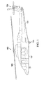
- Rotorcraft 101 has a rotor system 103 with a plurality of rotor blades 105. The pitch of each rotor blade 105 can be selectively controlled in order to selectively control direction, thrust, and lift of rotorcraft 101.
- Rotorcraft 101 further includes a fuselage 107, anti-torque system 109, and an empennage 111.
- Rotorcraft 101 further includes a landing gear system 113 to provide ground support for the aircraft. It should be appreciated that rotorcraft 101 is merely illustrative of a variety of aircraft that can implement the embodiments disclosed herein.
- aircraft implementations can include hybrid aircraft, tilt rotor aircraft, unmanned aircraft, gyrocopters, and a variety of helicopter configurations, to name a few examples. It should be appreciated that even though aircraft are particularly well suited to implement the embodiments of the present disclosure, non-aircraft vehicles and devices can also implement the embodiments.
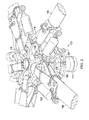
- Rotor hub 103 includes a yoke 109 coupled to a mast 113. Each rotor blade 105 is coupled to the yoke 115 with a grip 119. An inboard portion of each grip 119 is secured within an opening of the yoke 115 with a centrifugal force bearing 135. Rotor blade 105 is attached to the outboard portion of grip 119. A pitch horn 123 is interposed between rotor blade 105 and grip 119. A damper 121 is attached between yoke 115 and pitch horn 123. A pitch link 125 transfers pitch changes from a swashplate 127 to pitch horn 123. During operation, pitch link 125 can endure a high frequency of cycles.
- Pitch link 125 can include a link body 201 coupled between a first rod end 203 and a second rod end 205 that are substantially similar to each other.
- Rod end 203 can include a housing 207 and a shaft 209.
- Housing 207 is adapted for securing a bearing 211 therein.
- bearing 211 is swaged into housing 207; however, it should be appreciated that bearing 211 can be coupled into housing 207 in other ways, such as adhesive bonding.
- bearing 211 is integral with housing.
- Bearing 211 is illustrated as a spherical type bearing for exemplary purposes.
- Bearing 211 can include ball 213 having an attachment hole 215 located therethrough.
- Ball 213 fits within a race 217 that has an interior spherical surface with a liner 219 thereon.
- An outer surface of race 217 has an outer diameter that is configured for securedly locating within a component or structure, such as housing 207 of rod end 203, for example.
- Ball 213 is configured to rotate in relation to liner 219, such that the outer surface of ball 213 rubs against the friction surface of liner 219.
- Liner 219 is preferably made with a material having a low coefficient of friction, such as polytetrafluoroethylene (PTFE).
- PTFE polytetrafluoroethylene
- Bearing 211 includes a wafer 221 embedded in liner 219.
- Wafer 221 is an electrically conductive material that has a defined volume with a known electrical resistance.
- Leads 223 are electrically coupled to both wafer 221 and a terminal 225.
- Terminal 225 is located at an easily accessible external surface, such as on an outer surface of race 217.
- Leads 223 can be embedded in liner 219 or located between liner 219 and race 217.
- a wear surface B1 of wafer 221 is configured to wear as liner 219 wears, while a surface A1 is fixed to the inner surface of race 217. As wear surface B1 is eroded, the thickness T1 between surfaces A1 and B1 is reduced, resulting in a reduction in wafer volume and resistance.
- wafer 221 is approximately ring shaped with an outer radial surface A1 and inner radial surface B1 that are concentric.
- An axis 227 corresponding with axial loads of pitch link 125 intersects wafer 221 twice.
- a center of wafer 221 intersects both axis 227 and hole axis 229.
- a predicted wear pattern will be most severe at the locations at either intersect of axis 227 and wafer 221.
- the ring geometry of wafer 221 allows bearing 211 to be located in any orientation within housing 207 while maintaining two intersections with axis 227, thus insuring that wafer 221 will be subjected to the most severe wear within the wear pattern, regardless of the orientation of bearing 211 within housing 207.
- Wafer 221 and liner 219 can be attached to the interior of race 217 in a number of different methods.
- One method is to locate and bond wafer 221 around the centerline interior of race 217 prior to injection molding liner 219 adjacently to both sides of wafer 221 onto the interior of race 217.
- an Ohm meter can be coupled to leads 223 at terminal 225 to measure the resistance of wafer 221.
- the measured resistance can be compared to an initial or pre-worn resistance in order to calculate a wear percentage of wafer 221, which corresponds to a wear percentage of liner 219.
- leads 223 are electrically coupled to a monitoring system in the aircraft such that the wear percentage of wafer 221 and liner 219 can be accessed and read on a display within the aircraft.
- the resistance measurement of wafer 221 is wirelessly transmitted to a receiver to avoid the time and effort associated with manually coupling an Ohm meter to terminal 225.
- even manually coupling an Ohm meter to terminal 225 to calculate a percentage of wear of liner 219 is much more accurate and efficient compared with the conventional methods of testing for wear of liner 219.
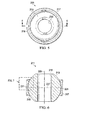
- Bearing 911 illustrated in Figures 9-12 is substantially similar in form and function as the bearing 211 illustrated in Figures 5-8 , except for the geometry and location of wafer 921.
- the geometry of wafer 921 can be such that the lengthwise axis of wafer 921 extends from a first face 229 to a second face 231 of race 217.
- the wafer 921 intersects axis 227, axis 227 corresponding with an axial load path of pitch link 125.
- wafer 921 has an arc shaped volume extends from first face 229 to second face 231 rather than being a ring shaped member similar to wafer 221.
- bearings 211 and 921 can be incorporated into a swashplate drive link, anti-drive link, control link, tail rotor pitch link, and lined journal bearings, to name a few examples.
Landscapes
- Engineering & Computer Science (AREA)
- General Engineering & Computer Science (AREA)
- Mechanical Engineering (AREA)
- Aviation & Aerospace Engineering (AREA)
- Physics & Mathematics (AREA)
- General Physics & Mathematics (AREA)
- Rolling Contact Bearings (AREA)
Abstract
Description
- The present disclosure relates to a system and method for monitoring wear in a bearing.
- Bearings can be used in a wide variety of implementations. One conventional implementation is the use of a rod end bearing in a rotor system of a helicopter. The rod end can have a liner between the ball and the race in order to reduce friction therebetween. Over time, the liner can wear away and necessitate replacement of the bearing. Conventionally, the amount of wear is detected by applying a load and measuring the amount of relative motion between the ball and the race of the bearing. This process is labor intensive, inaccurate, and can require special procedures and equipment to perform.
- There is a need for an improved system and method of monitoring wear in a bearing.
- The novel features believed characteristic of the embodiments of the present disclosure are set forth in the appended claims. However, the embodiments themselves, as well as a preferred mode of use, and further objectives and advantages thereof, will best be understood by reference to the following detailed description when read in conjunction with the accompanying drawings, wherein:
-
Figure 1 is a side view of a rotorcraft, according to an example embodiment; -
Figure 2 is perspective view of the rotor hub of the rotorcraft, according to an example embodiment; -
Figure 3 is a perspective view of a pitch link, according to an example embodiment; -
Figure 4 is a perspective view of a rod end having a spherical bearing, according to an example embodiment; -
Figure 5 is a side view of a bearing, according to an example embodiment; -
Figure 6 is a cross-sectional view of the bearing, taken from section lines 6-6 inFigure 5 , according to an example embodiment; -
Figure 7 is a detail view of the bearing, according to an example embodiment; -
Figure 8 is a perspective view of a wafer, according to an example embodiment; -
Figure 9 is a side view of a bearing, according to another example embodiment; -
Figure 10 is a cross-sectional view of the bearing, taken from section lines 10-10 inFigure 9 , according to an example embodiment; -
Figure 11 is a detail view of the bearing, according to an example embodiment; and -
Figure 12 is a perspective view of a wafer, according to an example embodiment. - Illustrative embodiments of the system and method are described below. In the interest of clarity, all features of an actual implementation may not be described in this specification. It will of course be appreciated that in the development of any such actual embodiment, numerous implementation-specific decisions must be made to achieve the developer's specific goals, such as compliance with system-related and business-related constraints, which will vary from one implementation to another. Moreover, it will be appreciated that such a development effort might be complex and time-consuming but would nevertheless be a routine undertaking for those of ordinary skill in the art having the benefit of this disclosure.
- In the specification, reference may be made to the spatial relationships between various components and to the spatial orientation of various aspects of components as the devices are depicted in the attached drawings. However, as will be recognized by those skilled in the art after a complete reading of the present application, the devices, members, apparatuses, etc. described herein may be positioned in any desired orientation. Thus, the use of terms such as "above," "below," "upper," "lower," or other like terms to describe a spatial relationship between various components or to describe the spatial orientation of aspects of such components should be understood to describe a relative relationship between the components or a spatial orientation of aspects of such components, respectively, as the device described herein may be oriented in any desired direction.
- Referring now to
Figure 1 in the drawings, a rotorcraft 101 is illustrated. Rotorcraft 101 has arotor system 103 with a plurality ofrotor blades 105. The pitch of eachrotor blade 105 can be selectively controlled in order to selectively control direction, thrust, and lift of rotorcraft 101. Rotorcraft 101 further includes afuselage 107,anti-torque system 109, and anempennage 111. Rotorcraft 101 further includes alanding gear system 113 to provide ground support for the aircraft. It should be appreciated that rotorcraft 101 is merely illustrative of a variety of aircraft that can implement the embodiments disclosed herein. Other aircraft implementations can include hybrid aircraft, tilt rotor aircraft, unmanned aircraft, gyrocopters, and a variety of helicopter configurations, to name a few examples. It should be appreciated that even though aircraft are particularly well suited to implement the embodiments of the present disclosure, non-aircraft vehicles and devices can also implement the embodiments. - Referring also to
Figure 2 in the drawings,rotor hub 103 is illustrated in further detail.Rotor hub 103 includes ayoke 109 coupled to amast 113. Eachrotor blade 105 is coupled to theyoke 115 with agrip 119. An inboard portion of eachgrip 119 is secured within an opening of theyoke 115 with a centrifugal force bearing 135.Rotor blade 105 is attached to the outboard portion ofgrip 119. Apitch horn 123 is interposed betweenrotor blade 105 andgrip 119. Adamper 121 is attached betweenyoke 115 andpitch horn 123. Apitch link 125 transfers pitch changes from aswashplate 127 to pitchhorn 123. During operation,pitch link 125 can endure a high frequency of cycles. - Referring now also to
Figures 3 and 4 ,pitch link 125 is illustrated in further detail.Pitch link 125 can include alink body 201 coupled between afirst rod end 203 and asecond rod end 205 that are substantially similar to each other.Rod end 203 can include ahousing 207 and ashaft 209.Housing 207 is adapted for securing abearing 211 therein. In the illustrated embodiment, bearing 211 is swaged intohousing 207; however, it should be appreciated that bearing 211 can be coupled intohousing 207 in other ways, such as adhesive bonding. In another embodiment, bearing 211 is integral with housing.Bearing 211 is illustrated as a spherical type bearing for exemplary purposes. - Referring now also to
Figures 5-8 , one example embodiment of bearing 211 is illustrated in further detail.Bearing 211 can includeball 213 having anattachment hole 215 located therethrough.Ball 213 fits within arace 217 that has an interior spherical surface with aliner 219 thereon. An outer surface ofrace 217 has an outer diameter that is configured for securedly locating within a component or structure, such ashousing 207 ofrod end 203, for example.Ball 213 is configured to rotate in relation toliner 219, such that the outer surface ofball 213 rubs against the friction surface ofliner 219.Liner 219 is preferably made with a material having a low coefficient of friction, such as polytetrafluoroethylene (PTFE). -
Bearing 211 includes awafer 221 embedded inliner 219. Wafer 221 is an electrically conductive material that has a defined volume with a known electrical resistance.Leads 223 are electrically coupled to bothwafer 221 and a terminal 225.Terminal 225 is located at an easily accessible external surface, such as on an outer surface ofrace 217.Leads 223 can be embedded inliner 219 or located betweenliner 219 andrace 217. A wear surface B1 ofwafer 221 is configured to wear asliner 219 wears, while a surface A1 is fixed to the inner surface ofrace 217. As wear surface B1 is eroded, the thickness T1 between surfaces A1 and B1 is reduced, resulting in a reduction in wafer volume and resistance. In the illustrated embodiment,wafer 221 is approximately ring shaped with an outer radial surface A1 and inner radial surface B1 that are concentric. Anaxis 227 corresponding with axial loads ofpitch link 125 intersectswafer 221 twice. A center ofwafer 221 intersects bothaxis 227 andhole axis 229. A predicted wear pattern will be most severe at the locations at either intersect ofaxis 227 andwafer 221. The ring geometry ofwafer 221 allows bearing 211 to be located in any orientation withinhousing 207 while maintaining two intersections withaxis 227, thus insuring thatwafer 221 will be subjected to the most severe wear within the wear pattern, regardless of the orientation of bearing 211 withinhousing 207. -
Wafer 221 andliner 219 can be attached to the interior ofrace 217 in a number of different methods. One method is to locate andbond wafer 221 around the centerline interior ofrace 217 prior toinjection molding liner 219 adjacently to both sides ofwafer 221 onto the interior ofrace 217. - During operation,
wafer 221 is worn at the same rate asliner 219. In order to easily quantify the amount of wear ofliner 219, an Ohm meter can be coupled toleads 223 atterminal 225 to measure the resistance ofwafer 221. The measured resistance can be compared to an initial or pre-worn resistance in order to calculate a wear percentage ofwafer 221, which corresponds to a wear percentage ofliner 219. In another embodiment, leads 223 are electrically coupled to a monitoring system in the aircraft such that the wear percentage ofwafer 221 andliner 219 can be accessed and read on a display within the aircraft. In another embodiment, the resistance measurement ofwafer 221 is wirelessly transmitted to a receiver to avoid the time and effort associated with manually coupling an Ohm meter toterminal 225. However it should be appreciated that even manually coupling an Ohm meter toterminal 225 to calculate a percentage of wear ofliner 219 is much more accurate and efficient compared with the conventional methods of testing for wear ofliner 219. - Referring now also to
Figures 9-12 , another embodiment of bearing 211 is illustrated. Bearing 911 illustrated inFigures 9-12 is substantially similar in form and function as the bearing 211 illustrated inFigures 5-8 , except for the geometry and location ofwafer 921. As illustrated inFigures 9-12 , the geometry ofwafer 921 can be such that the lengthwise axis ofwafer 921 extends from afirst face 229 to asecond face 231 ofrace 217. Thewafer 921 intersectsaxis 227,axis 227 corresponding with an axial load path ofpitch link 125. Thuswafer 921 has an arc shaped volume extends fromfirst face 229 tosecond face 231 rather than being a ring shaped member similar towafer 221. - The embodiments herein are illustrated with regard to a pitch link on a main rotor assembly on a rotorcraft; however, it should be appreciated that the embodiments may be adaptable to any bearing and structure incorporating such a bearing. For example,
bearings - The particular embodiments disclosed above are illustrative only, as the apparatus may be modified and practiced in different but equivalent manners apparent to those skilled in the art having the benefit of the teachings herein. Modifications, additions, or omissions may be made to the apparatuses described herein without departing from the scope of the invention. The components of the apparatus may be integrated or separated. Moreover, the operations of the apparatus may be performed by more, fewer, or other components.
- Furthermore, no limitations are intended to the details of construction or design herein shown, other than as described in the claims below. It is therefore evident that the particular embodiments disclosed above may be altered or modified and all such variations are considered within the scope and spirit of the application. Accordingly, the protection sought herein is as set forth in the claims below.
- To aid the Patent Office, and any readers of any patent issued on this application in interpreting the claims appended hereto, applicants wish to note that they do not intend any of the appended claims to invoke
paragraph 6 of 35 U.S.C. § 112 as it exists on the date of filing hereof unless the words "means for" or "step for" are explicitly used in the particular claim.
Claims (15)
- A bearing, comprising:a ball member;a race;a liner located on an interior surface of the race, the liner having a first surface bonded to an interior surface of the race, the liner having a second surface that is adjacent to the ball member; anda wafer having a wear surface that is aligned with the second surface of the liner, the wafer being an electrically conductive member.
- The bearing according to claim 1, wherein the ball member has a hole located therethrough.
- The bearing according to claim 1 or claim 2, further comprising:a first lead and second lead electrically coupled to the wafer, andoptionally or preferably a terminal coupled to the first lead and the second lead.
- The bearing according to claim 3, wherein the terminal is located on an exposed surface of the bearing, or wherein the terminal is located on an exposed surface of the race.
- The bearing according to claim 1 or any preceding claim, wherein the liner includes a polytetrafluoroethylene material.
- The bearing according to claim 1 or any preceding claim, wherein the wafer is a ring shaped member that is concentric with a centerline axis of the race.
- The bearing according to claim 1 or any of claims 2 to 5, wherein(i) the wafer is an arc shaped member that extends from a first face of the race to a second face of the race, and/or(ii) the wafer is an arc shaped member that intersects an axial load path axis of the bearing.
- The bearing according to claim 1 or any preceding claim, wherein the wafer is configured to wear along with the liner, and/or wherein the wafer has a known resistance that changes as the wafer wears.
- The bearing according to claim 1 or any preceding claim, wherein the race is configured to be attached to a structure, and optionally or preferably wherein the structure is a rod end.
- A pitch link for an aircraft, the pitch link comprising:a body member;a rod end coupled to the body member, the rod end comprising:a ball member;a race;a liner located on an interior surface of the race, the liner having a first surface bonded to an interior surface of the race, the liner having a second surface that is adjacent to the ball member; anda wafer having a wear surface that is aligned with the second surface of the liner, the wafer being an electrically conductive member.
- The pitch link according to claim 10, the rod end further comprising:a first lead and second lead electrically coupled to the wafer, and optionally or preferably further comprising:a terminal coupled to the first lead and the second lead.
- The pitch link according to claim 11, wherein the first lead and the second lead are coupled to wear monitoring system within the aircraft, and/or wherein the first lead and the second lead are coupled to a wireless transmitting device.
- A pitch link having a bearing in accordance with any of claims 1 to 9.
- An aircraft, for example a rotor aircraft, having a bearing in accordance with any of claims 1 to 9 or a pitch link in accordance with any of claims 10 to 13.
- A method of detecting wear in a bearing, the method comprising:establishing a known resistance of a wafer located in a liner on an interior of a bearing race;operating the bearing so that the wafer and the liner wears;measuring a resistance of the wafer; andcalculating a percentage of wear of the liner based upon a difference between the known resistance of the wafer and the measured resistance of the wafer.
Applications Claiming Priority (1)
| Application Number | Priority Date | Filing Date | Title |
|---|---|---|---|
| US14/041,396 US9157474B2 (en) | 2013-09-30 | 2013-09-30 | System and method of monitoring wear in a bearing |
Publications (2)
| Publication Number | Publication Date |
|---|---|
| EP2853756A1 true EP2853756A1 (en) | 2015-04-01 |
| EP2853756B1 EP2853756B1 (en) | 2015-12-09 |
Family
ID=49911389
Family Applications (1)
| Application Number | Title | Priority Date | Filing Date |
|---|---|---|---|
| EP14150078.5A Active EP2853756B1 (en) | 2013-09-30 | 2014-01-02 | System and method of monitoring wear in a bearing |
Country Status (3)
| Country | Link |
|---|---|
| US (1) | US9157474B2 (en) |
| EP (1) | EP2853756B1 (en) |
| CA (1) | CA2865134C (en) |
Cited By (3)
| Publication number | Priority date | Publication date | Assignee | Title |
|---|---|---|---|---|
| EP2955395B1 (en) * | 2014-06-12 | 2020-08-12 | Kamatics Corporation | Electrically conductive bearing system and manufacturing method |
| FR3096747A1 (en) * | 2019-05-29 | 2020-12-04 | Airbus Helicopters | SMOOTH BEARING, GIRAVION ROTOR COMPASS AND ASSOCIATED ROTOR |
| EP4116190A1 (en) * | 2021-07-07 | 2023-01-11 | Textron Innovations Inc. | Wear estimation for wear liner bearings |
Families Citing this family (10)
| Publication number | Priority date | Publication date | Assignee | Title |
|---|---|---|---|---|
| US9085357B2 (en) * | 2011-11-15 | 2015-07-21 | Textron Innovations Inc. | Rotor hub bearing system |
| DE102012206755B4 (en) * | 2012-04-25 | 2022-11-24 | Zf Friedrichshafen Ag | control rod arrangement |
| US20150078909A1 (en) * | 2013-09-16 | 2015-03-19 | Bell Helicopter Textron Inc. | Rotor blade and structural system for coupling the rotor blade in a rotor hub |
| US20150117804A1 (en) * | 2013-10-30 | 2015-04-30 | United Technologies Corporation | Gas turbine engine bushing |
| US9874494B2 (en) * | 2014-08-28 | 2018-01-23 | Nanolab, Inc. | Sensor for wear measurement of a bearing |
| CN108267271A (en) * | 2016-12-30 | 2018-07-10 | 天津市赫恩思体育用品有限公司 | One bulb liner air-tightness detection device |
| JP7372786B2 (en) * | 2019-09-02 | 2023-11-01 | 川崎重工業株式会社 | Spherical joint and robot joint structure equipped with the same |
| CN112550693B (en) * | 2021-02-26 | 2021-05-14 | 四川腾盾科技有限公司 | An unmanned helicopter automatic tilter structure |
| US11962132B2 (en) * | 2021-11-11 | 2024-04-16 | S&C Electric Company | Support bracket for transformer switch utilizing existing transformer connection points |
| EP4582707A1 (en) * | 2024-01-04 | 2025-07-09 | Denis Browne | Spherical joint bearing for an articulated vehicle, articulated vehicle and method for operating an articulated vehicle |
Citations (4)
| Publication number | Priority date | Publication date | Assignee | Title |
|---|---|---|---|---|
| JPS566911A (en) * | 1979-06-27 | 1981-01-24 | Hino Motors Ltd | Ball joint |
| DE102005059165A1 (en) * | 2005-12-12 | 2007-06-21 | Robert Bosch Gmbh | Method for wear detection on a shaft-bearing combination, in particular in a fuel pump |
| JP2011158057A (en) * | 2010-02-03 | 2011-08-18 | Somic Ishikawa Inc | Ball joint and ball joint device |
| EP2610168A1 (en) * | 2011-12-28 | 2013-07-03 | Bell Helicopter Textron Inc. | Adjustable pitch link |
Family Cites Families (21)
| Publication number | Priority date | Publication date | Assignee | Title |
|---|---|---|---|---|
| US3471207A (en) * | 1966-07-21 | 1969-10-07 | Heim Universal Corp | Bearing liner having etched particles embedded therein |
| US3786695A (en) * | 1972-04-28 | 1974-01-22 | Boeing Co | Redundant pitch link |
| US4248486A (en) * | 1978-12-15 | 1981-02-03 | Pneumo Corporation | Spherical bearing assembly with stress relief |
| US4657412A (en) * | 1985-03-25 | 1987-04-14 | The Torrington Company | Variable preload bearing assembly |
| IT1196801B (en) * | 1986-11-25 | 1988-11-25 | Agusta Aeronaut Costr | HELICOPTER ROTOR |
| US4850719A (en) * | 1988-09-12 | 1989-07-25 | The Torrington Company | Bearing with adjustable stiffness |
| US5730693A (en) * | 1996-01-02 | 1998-03-24 | Krayenhagen; Everett D. | Web tension control system |
| JP3624998B2 (en) * | 1996-09-30 | 2005-03-02 | 光洋精工株式会社 | Rolling bearing |
| GB2380528B (en) * | 2001-10-05 | 2003-09-10 | Minebea Co Ltd | A bearing assembly and method of manufacturing a bearing assembly |
| US6729763B2 (en) * | 2001-11-16 | 2004-05-04 | Kamatics Corporation | Hybrid bearing system |
| US6902341B1 (en) * | 2002-12-12 | 2005-06-07 | Mark C. Rauschert | Turnbuckle linkage assembly |
| JP2005133876A (en) * | 2003-10-31 | 2005-05-26 | Ntn Corp | Electrical corrosion prevention rolling bearing |
| US7520691B2 (en) * | 2004-06-24 | 2009-04-21 | ZF Lemförder Metallwaren AG | Protected stabilizer link or tie rod and ball race protecting cap |
| US7568841B2 (en) * | 2005-07-18 | 2009-08-04 | Deere & Company | Ball end for a link |
| JP4444901B2 (en) * | 2005-10-13 | 2010-03-31 | 株式会社ソミック石川 | Ball joint and ball joint device |
| TWI466205B (en) * | 2006-06-06 | 2014-12-21 | Advanced Inquiry Systems Inc | Methods and apparatus for bimodal wafer testing |
| EP2041442A1 (en) * | 2006-07-13 | 2009-04-01 | Roller Bearing Company of America, Inc. | Hybrid spherical bearing |
| GB0805224D0 (en) * | 2008-03-20 | 2008-04-30 | Minebea Co Ltd | An aerospace bearing component |
| US8529136B2 (en) * | 2009-03-30 | 2013-09-10 | Wafertech, Llc | High temperature ball bearing |
| DE102010017530A1 (en) * | 2010-06-23 | 2011-12-29 | Roth & Rau Ag | Roller furnace for use in industry for e.g. annealing wafer, has roller bearing partially provided within thermal furnace side insulation part that comprises ducts for rollers, where roller guides are provided at end faces of rollers |
| KR20160002686A (en) * | 2013-04-26 | 2016-01-08 | 술저 매니지멘트 에이지 | Method for assessing a wear state of a module of a turbomachine, module, and turbomachine |
-
2013
- 2013-09-30 US US14/041,396 patent/US9157474B2/en active Active
-
2014
- 2014-01-02 EP EP14150078.5A patent/EP2853756B1/en active Active
- 2014-09-24 CA CA2865134A patent/CA2865134C/en active Active
Patent Citations (4)
| Publication number | Priority date | Publication date | Assignee | Title |
|---|---|---|---|---|
| JPS566911A (en) * | 1979-06-27 | 1981-01-24 | Hino Motors Ltd | Ball joint |
| DE102005059165A1 (en) * | 2005-12-12 | 2007-06-21 | Robert Bosch Gmbh | Method for wear detection on a shaft-bearing combination, in particular in a fuel pump |
| JP2011158057A (en) * | 2010-02-03 | 2011-08-18 | Somic Ishikawa Inc | Ball joint and ball joint device |
| EP2610168A1 (en) * | 2011-12-28 | 2013-07-03 | Bell Helicopter Textron Inc. | Adjustable pitch link |
Cited By (4)
| Publication number | Priority date | Publication date | Assignee | Title |
|---|---|---|---|---|
| EP2955395B1 (en) * | 2014-06-12 | 2020-08-12 | Kamatics Corporation | Electrically conductive bearing system and manufacturing method |
| FR3096747A1 (en) * | 2019-05-29 | 2020-12-04 | Airbus Helicopters | SMOOTH BEARING, GIRAVION ROTOR COMPASS AND ASSOCIATED ROTOR |
| EP4116190A1 (en) * | 2021-07-07 | 2023-01-11 | Textron Innovations Inc. | Wear estimation for wear liner bearings |
| US12130199B2 (en) | 2021-07-07 | 2024-10-29 | Textron Innovations Inc. | Wear estimation for wear liner bearings |
Also Published As
| Publication number | Publication date |
|---|---|
| EP2853756B1 (en) | 2015-12-09 |
| US9157474B2 (en) | 2015-10-13 |
| CA2865134A1 (en) | 2015-03-30 |
| CA2865134C (en) | 2016-08-30 |
| US20150093059A1 (en) | 2015-04-02 |
Similar Documents
| Publication | Publication Date | Title |
|---|---|---|
| US9157474B2 (en) | System and method of monitoring wear in a bearing | |
| US9284849B2 (en) | Device for monitoring the flapping and/or lag behavior of a blade of a rotorcraft rotor | |
| US20120257847A1 (en) | Rotary wing aircraft instrumented motion control bearings | |
| US11208204B2 (en) | Rotorcraft elastomeric bearing assembly | |
| EP3280993B1 (en) | Bearing with wear sensor | |
| EP2578493B1 (en) | Elastomeric bearing with tapered shims | |
| US10222297B2 (en) | Non-contact infrared temperature sensor for health monitoring of rotorcraft bearings | |
| EP3293110B1 (en) | Core material for balanced rotor blade | |
| JP2007247899A (en) | Rotary wing aircraft ball bearing | |
| US10752341B2 (en) | Tip clearance harmonic estimation | |
| EP2905224B1 (en) | Rotor state sensor system | |
| EP3441309B1 (en) | Adjustable blade balance module | |
| US20130092786A1 (en) | Interferometric strain field sensor system for measuring rotor state | |
| EP3653496B1 (en) | Sensor for monitoring rotors | |
| US20180281937A1 (en) | Rigid rotor head with tension torsion (tt) strap retention | |
| EP2799730B1 (en) | Hybrid sliding element and elastomeric bearing | |
| US11015652B2 (en) | Hybrid elastomeric self-lubricated bearing | |
| EP4116190B1 (en) | Wear estimation for wear liner bearings | |
| EP4049931B1 (en) | Downstop load sensing system | |
| US10450060B2 (en) | Elastomeric bearing with tab for thermocouple and system for use | |
| US11104431B2 (en) | Rotor blade snubber retainer for a rotary wing aircraft | |
| US11319986B2 (en) | System and a method for detecting wear of a ball-joint connection device of a rod, a rotor assembly, and an aircraft | |
| US11111012B2 (en) | Hub with integral elastomeric bearing | |
| CN114537656A (en) | Rotor assembly for a rotorcraft | |
| EP2735850B1 (en) | Low impedance equipment interface |
Legal Events
| Date | Code | Title | Description |
|---|---|---|---|
| PUAI | Public reference made under article 153(3) epc to a published international application that has entered the european phase |
Free format text: ORIGINAL CODE: 0009012 |
|
| 17P | Request for examination filed |
Effective date: 20140102 |
|
| AK | Designated contracting states |
Kind code of ref document: A1 Designated state(s): AL AT BE BG CH CY CZ DE DK EE ES FI FR GB GR HR HU IE IS IT LI LT LU LV MC MK MT NL NO PL PT RO RS SE SI SK SM TR |
|
| AX | Request for extension of the european patent |
Extension state: BA ME |
|
| RIC1 | Information provided on ipc code assigned before grant |
Ipc: G01M 13/04 20060101ALI20150710BHEP Ipc: F16C 17/24 20060101ALI20150710BHEP Ipc: F16C 11/06 20060101ALI20150710BHEP Ipc: B64D 45/00 20060101ALI20150710BHEP Ipc: B64C 27/605 20060101AFI20150710BHEP |
|
| REG | Reference to a national code |
Ref country code: DE Ref legal event code: R079 Ref document number: 602014000530 Country of ref document: DE Free format text: PREVIOUS MAIN CLASS: F16C0011060000 Ipc: B60B0007080000 |
|
| GRAP | Despatch of communication of intention to grant a patent |
Free format text: ORIGINAL CODE: EPIDOSNIGR1 |
|
| RIC1 | Information provided on ipc code assigned before grant |
Ipc: B60B 7/08 20060101AFI20150825BHEP Ipc: F16C 33/78 20060101ALI20150825BHEP Ipc: F16C 33/76 20060101ALI20150825BHEP Ipc: F16C 33/80 20060101ALI20150825BHEP Ipc: F16C 33/72 20060101ALI20150825BHEP |
|
| INTG | Intention to grant announced |
Effective date: 20150914 |
|
| GRAS | Grant fee paid |
Free format text: ORIGINAL CODE: EPIDOSNIGR3 |
|
| GRAA | (expected) grant |
Free format text: ORIGINAL CODE: 0009210 |
|
| AK | Designated contracting states |
Kind code of ref document: B1 Designated state(s): AL AT BE BG CH CY CZ DE DK EE ES FI FR GB GR HR HU IE IS IT LI LT LU LV MC MK MT NL NO PL PT RO RS SE SI SK SM TR |
|
| REG | Reference to a national code |
Ref country code: GB Ref legal event code: FG4D |
|
| REG | Reference to a national code |
Ref country code: AT Ref legal event code: REF Ref document number: 764392 Country of ref document: AT Kind code of ref document: T Effective date: 20151215 Ref country code: CH Ref legal event code: EP |
|
| REG | Reference to a national code |
Ref country code: IE Ref legal event code: FG4D |
|
| REG | Reference to a national code |
Ref country code: DE Ref legal event code: R096 Ref document number: 602014000530 Country of ref document: DE |
|
| REG | Reference to a national code |
Ref country code: FR Ref legal event code: PLFP Year of fee payment: 3 |
|
| REG | Reference to a national code |
Ref country code: LT Ref legal event code: MG4D |
|
| REG | Reference to a national code |
Ref country code: NL Ref legal event code: MP Effective date: 20151209 |
|
| PG25 | Lapsed in a contracting state [announced via postgrant information from national office to epo] |
Ref country code: LT Free format text: LAPSE BECAUSE OF FAILURE TO SUBMIT A TRANSLATION OF THE DESCRIPTION OR TO PAY THE FEE WITHIN THE PRESCRIBED TIME-LIMIT Effective date: 20151209 Ref country code: ES Free format text: LAPSE BECAUSE OF FAILURE TO SUBMIT A TRANSLATION OF THE DESCRIPTION OR TO PAY THE FEE WITHIN THE PRESCRIBED TIME-LIMIT Effective date: 20151209 Ref country code: NO Free format text: LAPSE BECAUSE OF FAILURE TO SUBMIT A TRANSLATION OF THE DESCRIPTION OR TO PAY THE FEE WITHIN THE PRESCRIBED TIME-LIMIT Effective date: 20160309 |
|
| REG | Reference to a national code |
Ref country code: AT Ref legal event code: MK05 Ref document number: 764392 Country of ref document: AT Kind code of ref document: T Effective date: 20151209 |
|
| PG25 | Lapsed in a contracting state [announced via postgrant information from national office to epo] |
Ref country code: NL Free format text: LAPSE BECAUSE OF FAILURE TO SUBMIT A TRANSLATION OF THE DESCRIPTION OR TO PAY THE FEE WITHIN THE PRESCRIBED TIME-LIMIT Effective date: 20151209 Ref country code: RS Free format text: LAPSE BECAUSE OF FAILURE TO SUBMIT A TRANSLATION OF THE DESCRIPTION OR TO PAY THE FEE WITHIN THE PRESCRIBED TIME-LIMIT Effective date: 20151209 Ref country code: SE Free format text: LAPSE BECAUSE OF FAILURE TO SUBMIT A TRANSLATION OF THE DESCRIPTION OR TO PAY THE FEE WITHIN THE PRESCRIBED TIME-LIMIT Effective date: 20151209 Ref country code: LV Free format text: LAPSE BECAUSE OF FAILURE TO SUBMIT A TRANSLATION OF THE DESCRIPTION OR TO PAY THE FEE WITHIN THE PRESCRIBED TIME-LIMIT Effective date: 20151209 Ref country code: BE Free format text: LAPSE BECAUSE OF NON-PAYMENT OF DUE FEES Effective date: 20160131 Ref country code: FI Free format text: LAPSE BECAUSE OF FAILURE TO SUBMIT A TRANSLATION OF THE DESCRIPTION OR TO PAY THE FEE WITHIN THE PRESCRIBED TIME-LIMIT Effective date: 20151209 Ref country code: GR Free format text: LAPSE BECAUSE OF FAILURE TO SUBMIT A TRANSLATION OF THE DESCRIPTION OR TO PAY THE FEE WITHIN THE PRESCRIBED TIME-LIMIT Effective date: 20160310 |
|
| PG25 | Lapsed in a contracting state [announced via postgrant information from national office to epo] |
Ref country code: IS Free format text: LAPSE BECAUSE OF FAILURE TO SUBMIT A TRANSLATION OF THE DESCRIPTION OR TO PAY THE FEE WITHIN THE PRESCRIBED TIME-LIMIT Effective date: 20151209 |
|
| PG25 | Lapsed in a contracting state [announced via postgrant information from national office to epo] |
Ref country code: CZ Free format text: LAPSE BECAUSE OF FAILURE TO SUBMIT A TRANSLATION OF THE DESCRIPTION OR TO PAY THE FEE WITHIN THE PRESCRIBED TIME-LIMIT Effective date: 20151209 |
|
| PG25 | Lapsed in a contracting state [announced via postgrant information from national office to epo] |
Ref country code: PT Free format text: LAPSE BECAUSE OF FAILURE TO SUBMIT A TRANSLATION OF THE DESCRIPTION OR TO PAY THE FEE WITHIN THE PRESCRIBED TIME-LIMIT Effective date: 20160411 Ref country code: IS Free format text: LAPSE BECAUSE OF FAILURE TO SUBMIT A TRANSLATION OF THE DESCRIPTION OR TO PAY THE FEE WITHIN THE PRESCRIBED TIME-LIMIT Effective date: 20160409 Ref country code: RO Free format text: LAPSE BECAUSE OF FAILURE TO SUBMIT A TRANSLATION OF THE DESCRIPTION OR TO PAY THE FEE WITHIN THE PRESCRIBED TIME-LIMIT Effective date: 20151209 Ref country code: SK Free format text: LAPSE BECAUSE OF FAILURE TO SUBMIT A TRANSLATION OF THE DESCRIPTION OR TO PAY THE FEE WITHIN THE PRESCRIBED TIME-LIMIT Effective date: 20151209 Ref country code: EE Free format text: LAPSE BECAUSE OF FAILURE TO SUBMIT A TRANSLATION OF THE DESCRIPTION OR TO PAY THE FEE WITHIN THE PRESCRIBED TIME-LIMIT Effective date: 20151209 Ref country code: LU Free format text: LAPSE BECAUSE OF FAILURE TO SUBMIT A TRANSLATION OF THE DESCRIPTION OR TO PAY THE FEE WITHIN THE PRESCRIBED TIME-LIMIT Effective date: 20160102 Ref country code: SM Free format text: LAPSE BECAUSE OF FAILURE TO SUBMIT A TRANSLATION OF THE DESCRIPTION OR TO PAY THE FEE WITHIN THE PRESCRIBED TIME-LIMIT Effective date: 20151209 Ref country code: AT Free format text: LAPSE BECAUSE OF FAILURE TO SUBMIT A TRANSLATION OF THE DESCRIPTION OR TO PAY THE FEE WITHIN THE PRESCRIBED TIME-LIMIT Effective date: 20151209 |
|
| REG | Reference to a national code |
Ref country code: DE Ref legal event code: R097 Ref document number: 602014000530 Country of ref document: DE |
|
| PG25 | Lapsed in a contracting state [announced via postgrant information from national office to epo] |
Ref country code: MC Free format text: LAPSE BECAUSE OF FAILURE TO SUBMIT A TRANSLATION OF THE DESCRIPTION OR TO PAY THE FEE WITHIN THE PRESCRIBED TIME-LIMIT Effective date: 20151209 |
|
| PLBE | No opposition filed within time limit |
Free format text: ORIGINAL CODE: 0009261 |
|
| STAA | Information on the status of an ep patent application or granted ep patent |
Free format text: STATUS: NO OPPOSITION FILED WITHIN TIME LIMIT |
|
| PG25 | Lapsed in a contracting state [announced via postgrant information from national office to epo] |
Ref country code: PL Free format text: LAPSE BECAUSE OF FAILURE TO SUBMIT A TRANSLATION OF THE DESCRIPTION OR TO PAY THE FEE WITHIN THE PRESCRIBED TIME-LIMIT Effective date: 20151209 Ref country code: DK Free format text: LAPSE BECAUSE OF FAILURE TO SUBMIT A TRANSLATION OF THE DESCRIPTION OR TO PAY THE FEE WITHIN THE PRESCRIBED TIME-LIMIT Effective date: 20151209 |
|
| REG | Reference to a national code |
Ref country code: IE Ref legal event code: MM4A |
|
| 26N | No opposition filed |
Effective date: 20160912 |
|
| PG25 | Lapsed in a contracting state [announced via postgrant information from national office to epo] |
Ref country code: SI Free format text: LAPSE BECAUSE OF FAILURE TO SUBMIT A TRANSLATION OF THE DESCRIPTION OR TO PAY THE FEE WITHIN THE PRESCRIBED TIME-LIMIT Effective date: 20151209 |
|
| PG25 | Lapsed in a contracting state [announced via postgrant information from national office to epo] |
Ref country code: BE Free format text: LAPSE BECAUSE OF FAILURE TO SUBMIT A TRANSLATION OF THE DESCRIPTION OR TO PAY THE FEE WITHIN THE PRESCRIBED TIME-LIMIT Effective date: 20151209 |
|
| REG | Reference to a national code |
Ref country code: FR Ref legal event code: PLFP Year of fee payment: 4 |
|
| PG25 | Lapsed in a contracting state [announced via postgrant information from national office to epo] |
Ref country code: IE Free format text: LAPSE BECAUSE OF NON-PAYMENT OF DUE FEES Effective date: 20160102 |
|
| PG25 | Lapsed in a contracting state [announced via postgrant information from national office to epo] |
Ref country code: MT Free format text: LAPSE BECAUSE OF FAILURE TO SUBMIT A TRANSLATION OF THE DESCRIPTION OR TO PAY THE FEE WITHIN THE PRESCRIBED TIME-LIMIT Effective date: 20151209 |
|
| REG | Reference to a national code |
Ref country code: CH Ref legal event code: PL |
|
| PG25 | Lapsed in a contracting state [announced via postgrant information from national office to epo] |
Ref country code: CH Free format text: LAPSE BECAUSE OF NON-PAYMENT OF DUE FEES Effective date: 20170131 Ref country code: LI Free format text: LAPSE BECAUSE OF NON-PAYMENT OF DUE FEES Effective date: 20170131 |
|
| REG | Reference to a national code |
Ref country code: FR Ref legal event code: PLFP Year of fee payment: 5 |
|
| PG25 | Lapsed in a contracting state [announced via postgrant information from national office to epo] |
Ref country code: HU Free format text: LAPSE BECAUSE OF FAILURE TO SUBMIT A TRANSLATION OF THE DESCRIPTION OR TO PAY THE FEE WITHIN THE PRESCRIBED TIME-LIMIT; INVALID AB INITIO Effective date: 20140102 |
|
| PG25 | Lapsed in a contracting state [announced via postgrant information from national office to epo] |
Ref country code: HR Free format text: LAPSE BECAUSE OF FAILURE TO SUBMIT A TRANSLATION OF THE DESCRIPTION OR TO PAY THE FEE WITHIN THE PRESCRIBED TIME-LIMIT Effective date: 20151209 Ref country code: MK Free format text: LAPSE BECAUSE OF FAILURE TO SUBMIT A TRANSLATION OF THE DESCRIPTION OR TO PAY THE FEE WITHIN THE PRESCRIBED TIME-LIMIT Effective date: 20151209 Ref country code: CY Free format text: LAPSE BECAUSE OF FAILURE TO SUBMIT A TRANSLATION OF THE DESCRIPTION OR TO PAY THE FEE WITHIN THE PRESCRIBED TIME-LIMIT Effective date: 20151209 Ref country code: MT Free format text: LAPSE BECAUSE OF FAILURE TO SUBMIT A TRANSLATION OF THE DESCRIPTION OR TO PAY THE FEE WITHIN THE PRESCRIBED TIME-LIMIT Effective date: 20160131 |
|
| PG25 | Lapsed in a contracting state [announced via postgrant information from national office to epo] |
Ref country code: BG Free format text: LAPSE BECAUSE OF FAILURE TO SUBMIT A TRANSLATION OF THE DESCRIPTION OR TO PAY THE FEE WITHIN THE PRESCRIBED TIME-LIMIT Effective date: 20151209 |
|
| PG25 | Lapsed in a contracting state [announced via postgrant information from national office to epo] |
Ref country code: AL Free format text: LAPSE BECAUSE OF FAILURE TO SUBMIT A TRANSLATION OF THE DESCRIPTION OR TO PAY THE FEE WITHIN THE PRESCRIBED TIME-LIMIT Effective date: 20151209 Ref country code: TR Free format text: LAPSE BECAUSE OF FAILURE TO SUBMIT A TRANSLATION OF THE DESCRIPTION OR TO PAY THE FEE WITHIN THE PRESCRIBED TIME-LIMIT Effective date: 20151209 |
|
| P01 | Opt-out of the competence of the unified patent court (upc) registered |
Effective date: 20230602 |
|
| PGFP | Annual fee paid to national office [announced via postgrant information from national office to epo] |
Ref country code: GB Payment date: 20260127 Year of fee payment: 13 |
|
| PGFP | Annual fee paid to national office [announced via postgrant information from national office to epo] |
Ref country code: DE Payment date: 20260128 Year of fee payment: 13 |
|
| PGFP | Annual fee paid to national office [announced via postgrant information from national office to epo] |
Ref country code: IT Payment date: 20260121 Year of fee payment: 13 |
|
| PGFP | Annual fee paid to national office [announced via postgrant information from national office to epo] |
Ref country code: FR Payment date: 20260126 Year of fee payment: 13 |