EP2853729B1 - Wind turbine with a wind sensing apparatus - Google Patents
Wind turbine with a wind sensing apparatus Download PDFInfo
- Publication number
- EP2853729B1 EP2853729B1 EP13382377.3A EP13382377A EP2853729B1 EP 2853729 B1 EP2853729 B1 EP 2853729B1 EP 13382377 A EP13382377 A EP 13382377A EP 2853729 B1 EP2853729 B1 EP 2853729B1
- Authority
- EP
- European Patent Office
- Prior art keywords
- wind
- sensing apparatus
- support structure
- wind turbine
- tower
- Prior art date
- Legal status (The legal status is an assumption and is not a legal conclusion. Google has not performed a legal analysis and makes no representation as to the accuracy of the status listed.)
- Active
Links
- 238000001514 detection method Methods 0.000 claims description 9
- 238000005259 measurement Methods 0.000 description 10
- 238000000034 method Methods 0.000 description 5
- 230000007246 mechanism Effects 0.000 description 4
- 230000001427 coherent effect Effects 0.000 description 3
- 238000005452 bending Methods 0.000 description 2
- 230000006735 deficit Effects 0.000 description 2
- 238000012423 maintenance Methods 0.000 description 2
- 238000011144 upstream manufacturing Methods 0.000 description 2
- 239000000443 aerosol Substances 0.000 description 1
- 239000000428 dust Substances 0.000 description 1
- 230000000694 effects Effects 0.000 description 1
- 238000009434 installation Methods 0.000 description 1
- 230000003287 optical effect Effects 0.000 description 1
- 239000002245 particle Substances 0.000 description 1
Images


Classifications
-
- F—MECHANICAL ENGINEERING; LIGHTING; HEATING; WEAPONS; BLASTING
- F03—MACHINES OR ENGINES FOR LIQUIDS; WIND, SPRING, OR WEIGHT MOTORS; PRODUCING MECHANICAL POWER OR A REACTIVE PROPULSIVE THRUST, NOT OTHERWISE PROVIDED FOR
- F03D—WIND MOTORS
- F03D7/00—Controlling wind motors
- F03D7/02—Controlling wind motors the wind motors having rotation axis substantially parallel to the air flow entering the rotor
- F03D7/04—Automatic control; Regulation
- F03D7/042—Automatic control; Regulation by means of an electrical or electronic controller
- F03D7/048—Automatic control; Regulation by means of an electrical or electronic controller controlling wind farms
-
- F—MECHANICAL ENGINEERING; LIGHTING; HEATING; WEAPONS; BLASTING
- F03—MACHINES OR ENGINES FOR LIQUIDS; WIND, SPRING, OR WEIGHT MOTORS; PRODUCING MECHANICAL POWER OR A REACTIVE PROPULSIVE THRUST, NOT OTHERWISE PROVIDED FOR
- F03D—WIND MOTORS
- F03D17/00—Monitoring or testing of wind motors, e.g. diagnostics
-
- F—MECHANICAL ENGINEERING; LIGHTING; HEATING; WEAPONS; BLASTING
- F05—INDEXING SCHEMES RELATING TO ENGINES OR PUMPS IN VARIOUS SUBCLASSES OF CLASSES F01-F04
- F05B—INDEXING SCHEME RELATING TO WIND, SPRING, WEIGHT, INERTIA OR LIKE MOTORS, TO MACHINES OR ENGINES FOR LIQUIDS COVERED BY SUBCLASSES F03B, F03D AND F03G
- F05B2270/00—Control
- F05B2270/30—Control parameters, e.g. input parameters
- F05B2270/322—Control parameters, e.g. input parameters the detection or prediction of a wind gust
-
- F—MECHANICAL ENGINEERING; LIGHTING; HEATING; WEAPONS; BLASTING
- F05—INDEXING SCHEMES RELATING TO ENGINES OR PUMPS IN VARIOUS SUBCLASSES OF CLASSES F01-F04
- F05B—INDEXING SCHEME RELATING TO WIND, SPRING, WEIGHT, INERTIA OR LIKE MOTORS, TO MACHINES OR ENGINES FOR LIQUIDS COVERED BY SUBCLASSES F03B, F03D AND F03G
- F05B2270/00—Control
- F05B2270/80—Devices generating input signals, e.g. transducers, sensors, cameras or strain gauges
- F05B2270/804—Optical devices
- F05B2270/8042—Lidar systems
-
- F—MECHANICAL ENGINEERING; LIGHTING; HEATING; WEAPONS; BLASTING
- F05—INDEXING SCHEMES RELATING TO ENGINES OR PUMPS IN VARIOUS SUBCLASSES OF CLASSES F01-F04
- F05B—INDEXING SCHEME RELATING TO WIND, SPRING, WEIGHT, INERTIA OR LIKE MOTORS, TO MACHINES OR ENGINES FOR LIQUIDS COVERED BY SUBCLASSES F03B, F03D AND F03G
- F05B2270/00—Control
- F05B2270/80—Devices generating input signals, e.g. transducers, sensors, cameras or strain gauges
- F05B2270/806—Sonars
-
- Y—GENERAL TAGGING OF NEW TECHNOLOGICAL DEVELOPMENTS; GENERAL TAGGING OF CROSS-SECTIONAL TECHNOLOGIES SPANNING OVER SEVERAL SECTIONS OF THE IPC; TECHNICAL SUBJECTS COVERED BY FORMER USPC CROSS-REFERENCE ART COLLECTIONS [XRACs] AND DIGESTS
- Y02—TECHNOLOGIES OR APPLICATIONS FOR MITIGATION OR ADAPTATION AGAINST CLIMATE CHANGE
- Y02E—REDUCTION OF GREENHOUSE GAS [GHG] EMISSIONS, RELATED TO ENERGY GENERATION, TRANSMISSION OR DISTRIBUTION
- Y02E10/00—Energy generation through renewable energy sources
- Y02E10/70—Wind energy
- Y02E10/72—Wind turbines with rotation axis in wind direction
Definitions
- the present disclosure relates to wind turbines and wind anemometry.
- the performance of wind turbines is affected by turbulent wind conditions that cause structural loads on the wind turbine and its components.
- structural loads may be reduced by measuring incoming wind speed and wind turbulence in front of the wind turbine with remote wind sensing apparatuses.
- the data gathered by the wind sensing apparatuses may be used by feed-forward wind turbine controllers to proactively compensate for wind velocity and direction changes prior to impingement of the air flow on the wind turbine e.g. by adjusting the yaw of the nacelle and pitch angle of the blades to protect components and maximize the performance of the wind turbine.
- LIDAR light detecting and ranging
- CLR coherent laser radar
- CDL coherent Doppler LIDAR
- LIDAR involves the emission of a coherent light beam and detection of the weak return reflected or scattered from a distant target.
- the technique provides a way to measure the line-of-sight component of wind speed via detection of the Doppler shift for light backscattered from natural aerosols (particles of dust, pollen, droplets, etc.) in the atmosphere.
- Sonic detecting and ranging is another commonly used Doppler-based method of remote atmospheric wind profiling. It involves the emission of sound pulses and relies on the detection of the weak echo scattered from temperature and velocity fluctuations in the atmosphere. It measures the wind velocity via the Doppler shift of the acoustic pulses in a manner analogous to LIDAR.
- LIDAR LIDAR or SODAR mounting positioning options in wind turbines are currently known.
- a LIDAR may be mounted on the nacelle facing the incoming wind.
- the restricted field of view caused by the rotating blades of the turbine results in only approximately 75% of measurements being successful, with the laser beam striking a blade in the remaining 25% of cases. For the same reason, it takes longer to gather measurements.
- rearward-facing LIDAR may be mounted on the nacelle on a pan-and-tilt scanner to measure wake wind speed deficit and wander.
- the accuracy of the measurements taken by remote wind sensing apparatuses mounted on the nacelle or on the hub is furthermore affected by the bending moments and swaying experienced by the wind tower in strong winds.
- SODARs are less likely to be mounted on the nacelle or the hub because the noises generated at the nacelle and/or at the hub interfere with the SODAR's sonic signals.
- a known approach to overcome the known drawbacks of mounting the LIDAR or a SODAR on the nacelle or the hub is to position the LIDAR or the SODAR on the ground some distance ahead of the wind turbine and directed upwardly to measure wind speed and wind fluctuations of the wind in front of the wind turbine.
- JP2006125265 is related to a wind power generating device provided with a tower erectly provided on the ground, a nacelle fixed on the tower, and a plurality of blades rotatably fixed on the nacelle via a hub.
- a Doppler anemometer is provided.
- the Doppler anemometer is capable of measuring wind speed in front of the generating device by sending and receiving sound wave or electromagnetic wave.
- the generating devices is provided with blade angle control means.
- GB2481461 is related to a wind park comprising a plurality of wind turbines with a least one wind turbine downstream of at least one upstream turbine.
- the downstream turbine includes a Lidar or other device for sensing characteristics of the wake produced by the upstream turbine and for providing an output to an individual turbine controller or a wind park controller indicative of the measured wake.
- the controller controls parameters of the downstream turbine and possibly adjacent turbines in accordance with the wake indicative signals.
- US2013094961 provides methods, systems, and apparatus for determining a property of wind approaching a wind turbine.
- a light detection and ranging equipment may be used to determine a property of the wind at a plurality of locations ahead of a turbine.
- a wind flow model may be used to determine the property of wind expected at the rotor of the wind turbine based on the readings of the light detection and ranging device.
- this invention discloses a wind turbine comprising a rotor, a nacelle, a support structure for the nacelle and at least one wind sensing apparatus mounted on the support structure, wherein the support structure comprises a tower, wherein the wind sensing apparatus comprises at least one light detection and ranging apparatus, and wherein the at least one light detection and ranging apparatus is mounted on the support structure substantially near the base of the tower.
- the wind sensing apparatus may be more easily accessible for maintenance than in prior art solutions. Particularly in offshore applications, no separate structures would be needed for housing or supporting wind sensing apparatus and additionally the accuracy of wind measurements may be improved compared to some prior art systems. Furthermore, if placed low enough, the blades will not affect the measurements either.
- the wind sensing apparatus may be moveably mounted on the support structure such that the wind sensing apparatus is moveable along a surface of the support structure.
- the wind sensing apparatus may be moveable along a circumference of the support structure.
- the remote wind sensing apparatus may measure the speed and fluctuations of the wind at up to 360 degrees around the wind turbine and not only the incoming wind or the outgoing wake.
- the nacelle's support structure may comprise a standalone tower and, in other embodiments, the support structure may also comprise a substructure below the tower.
- the at least one wind sensing apparatus may be moveably mounted on the support structure, either on the tower or on the substructure below the tower.
- the remote wind sensing apparatus By positioning the remote wind sensing apparatus substantially near the base of the tower, the accuracy of the measurements of the remote wind sensing apparatus will not be affected by the bending moments and swaying experienced by the upper portion of the tower under strong winds. Furthermore, mounting and maintaining the remote wind sensing apparatus at the base of the tower is easier than doing so on the nacelle or on the hub.
- the wind turbine may comprise one or more mechanisms for moving the wind sensing apparatus along a surface of the support structure, i.e. the wind sensing apparatus may be moveable along a horizontal and a vertical axis of the support structure.
- the wind sensing apparatus may comprise a pan-and-tilt scanning capability, i.e. from any point along the surface of the support structure the wind sensing apparatus may be further rotatable around its own horizontal and vertical axis to further broaden the areas and directions around the wind turbine in which wind speed and wind turbulence may be measured.
- the wind turbine may be located offshore.
- An aspect of having the wind sensing apparatus mounted to the support structure is that there is no requirement for an additional costly marine platform which makes the remote wind sensing apparatus equally easy to install and maintain inland as it is offshore.
- the wind turbine may comprise a positioning controller for moving the at least one wind sensing apparatus along a surface of the tower and/or a control system for controlling parameters of the wind turbine in response to data captured by the at least one wind sensing apparatus.
- a wind park may comprise a plurality of wind turbines with wind sensing apparatuses moveably mounted to their support structures and a central positioning controller for moving one or more wind sensing apparatuses along the surface of the support structures of one or more wind turbines.
- the remote wind sensing apparatuses on one or more wind turbines may be managed to measure wind speed and wind fluctuations in multiple directions and, hence, provide a detailed interpretation of wind evolution and the transverse structure of gusts of wind around the wind turbines.
- the wind park may also comprise a central control system for controlling parameters of one or more wind turbines in response to data captured by one or more wind sensing apparatuses from one or more wind turbines located nearby.
- a central control system may be e.g. a SCADA system.
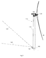
- FIG. 1 illustrates an embodiment of a wind turbine according to the present invention.
- the wind turbine 110 comprises a tower 115, a nacelle 120, a rotor 125 and rotor blades 130.
- the LIDAR 105 is moveably mounted around the circumference of the tower on a guiding rail 150 at the base of the tower and is forward-facing for measuring incoming wind speed and fluctuations.
- the vertical scanning range of the LIDAR is illustrated with a lower limit 140 which may be substantially horizontal and an upper limit 145 which may be limited by the lowest travel path of the rotor blades.
- the wind sensing apparatuses may be moveably mounted to the tower base with the aid of a platform with horizontal and/or vertical mechanisms for moveably mounting it to the support structure e.g. guiding rails.
- the wind sensing apparatus may be remotely controlled to move along the surface of the support structure by a positioning controller.
- the wind turbine may comprise a parameter management system for managing the variable parameters of the wind turbine in response to data captured by the at least one wind sensing apparatus.
- Figure 2 illustrates another view of the wind turbine depicted in figure 1 .
- the wind turbine in figure 2 is similar to the wind turbine in figure 1 with the exception that the wind sensing apparatus 105 has been moved along the guide rail 150 at the base of the tower in order to be rearward-facing for measuring wake wind deficit and wander.
- the vertical scanning range of the wind sensing apparatus is illustrated with a lower limit 140 which may be substantially horizontal and an upper limit 145 which is not limited by the rotor blades and, therefore, could be substantially vertical.
- the movable wind sensing apparatus when it is rearward-facing or side-facing, it may additionally be moved vertically along the height of the tower because neither the wind sensing apparatus' movement along the surface nor the scanning paths are obstructed by the rotor blades.
- the wind sensing apparatus may be mounted and moved along the surface of the support structure with a suitable mechanism, such as, for example vertical guide rails. These vertical guide rails could be combined in some embodiments with a plurality of circumferential rails.
- Alternative mechanisms include the use of cables and pulleys or with a robotic carrier capable of moving along the surface of the support structure by gripping the surface or gliding along it while carrying the wind sensing apparatus.
- FIG. 3 illustrates a further embodiment of the wind turbine according to the present invention.
- the wind turbine 310 comprises a rotor 325, rotor blades 330, a nacelle 320 and a support structure 355.
- the support structure comprises a tower 315 and a substructure 335 below the tower.
- the moveable wind sensing apparatus 305 is rotatably mounted on the tower, substantially near the base of the tower, and is forward-facing for measuring incoming wind speed and fluctuations.
- the wind sensing apparatus may be rotated 360 degrees along the circumference of the substructure below the tower in order to measure wind speeds and wind fluctuations in the atmosphere in any direction around the wind turbine.
- the vertical scanning range of the wind sensing apparatus is illustrated with a lower limit 340 which may be substantially horizontal and an upper limit 345 which may be limited by the lowest travel path of the rotor blades 330.
- FIG. 4 illustrates yet another embodiment of a wind turbine according to the present invention.
- the wind turbine 410 comprises a rotor 425, rotor blades 430, a nacelle 420 and a support structure 455, wherein the support structure comprises a tower 415 and a substructure 435 below the tower.
- the wind sensing apparatus 405 is rotatably mounted on the substructure below the tower, substantially near the base of the tower, and is forward-facing for measuring incoming wind speed and fluctuations.
- the wind sensing apparatus may be rotated 360 degrees along the circumference of the substructure below the tower in order to measure wind speeds and wind fluctuations in the atmosphere in any direction around the wind turbine.
- the vertical scanning range of the wind sensing apparatus is illustrated with a lower limit 440 which may be substantially horizontal and an upper limit 445 which is limited by the lowest travel path of the rotor blades 430.
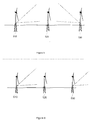
- Figure 5 illustrates yet a further embodiment of the wind turbine according to the present invention.
- the figure depicts a wind park with three offshore wind turbines where the wind sensing apparatus mounted on the support structure of the first wind turbine 510 may be forward-facing towards the second turbine 520 in order to measure the wake wind from the second turbine which is incoming towards the first wind turbine.
- the wind sensing apparatus mounted on the support structure of the third wind turbine 530 may be rearward-facing towards the second turbine in order to measure the wake wind from the third turbine which is incoming towards the second wind turbine.
- Figure 6 illustrates an alternative embodiment of the wind turbine according to the present invention.
- Figure 6 illustrates a wind park with three offshore wind turbines where the wind sensing apparatus mounted on the support structure of the first wind turbine 610 may be forward-facing towards the second turbine 620 in order to measure the wake wind from the second turbine which is incoming towards the first wind turbine whilst the wind sensing apparatus mounted on the support structure of the third wind turbine 630 may be moved to be forward-facing in order to measure the incoming wind towards it.
- the wind sensing apparatus may be mounted to be movable along a circumference of the support structure (tower) to be able to select where wind flows are to be measured.
- Figure 7 illustrates another alternative embodiment of the wind turbine according to the present invention.
- Figure 7 depicts a top-down view of a wind park comprising nine wind turbines (710, 720, 730, 740, 750, 760, 770, 780, 790), which illustrates an embodiment wherein the moveable wind sensing apparatuses of wind turbines 740 and 790 may be turned towards wind turbine 750 in order to measure wind speed, wind fluctuations, wake wind and transversal wind gusts affecting wind turbine 750.
- the wind sensing apparatus moveably mounted on wind turbine 730 may be directed to measure the wake wind from wind turbine 730 which is also the incoming wind to 720.
- the one or more moveable remote wind sensing apparatuses or wind sensing apparatuses may be moved along the surface of each wind turbine and directed to the area in the atmosphere where the wind speed and wind fluctuations are of interest.
- Wind measurements taken with a plurality of remote wind sensing apparatuses may provide a detailed interpretation of wind evolution and the transverse structure of gusts of wind around the wind turbines.
- the wind park may comprise a central positioning controller for controlling the position of each and all of the moveably mounted wind sensing apparatus in the wind park.
- the wind park may comprise a central control system for managing various parameters (e.g. pitch angles, generator torque, rotor speed etc.) of the wind turbines located in the wind park in response to data captured by the at least one of the plurality of wind sensing apparatuses mounted on the wind turbines in the park.
- a central control system may be a SCADA system.
Description
- The present disclosure relates to wind turbines and wind anemometry.
- The performance of wind turbines is affected by turbulent wind conditions that cause structural loads on the wind turbine and its components. Currently, structural loads may be reduced by measuring incoming wind speed and wind turbulence in front of the wind turbine with remote wind sensing apparatuses. The data gathered by the wind sensing apparatuses may be used by feed-forward wind turbine controllers to proactively compensate for wind velocity and direction changes prior to impingement of the air flow on the wind turbine e.g. by adjusting the yaw of the nacelle and pitch angle of the blades to protect components and maximize the performance of the wind turbine.
- A number of optical and acoustic methods allow remote measurement of wind speed in the atmosphere. These include the technique of light detecting and ranging (LIDAR), also referred to as coherent laser radar (CLR) and coherent Doppler LIDAR (CDL). LIDAR involves the emission of a coherent light beam and detection of the weak return reflected or scattered from a distant target. The technique provides a way to measure the line-of-sight component of wind speed via detection of the Doppler shift for light backscattered from natural aerosols (particles of dust, pollen, droplets, etc.) in the atmosphere.
- Sonic detecting and ranging (SODAR) is another commonly used Doppler-based method of remote atmospheric wind profiling. It involves the emission of sound pulses and relies on the detection of the weak echo scattered from temperature and velocity fluctuations in the atmosphere. It measures the wind velocity via the Doppler shift of the acoustic pulses in a manner analogous to LIDAR.
- Several LIDAR or SODAR mounting positioning options in wind turbines are currently known. A LIDAR may be mounted on the nacelle facing the incoming wind. However, the restricted field of view caused by the rotating blades of the turbine results in only approximately 75% of measurements being successful, with the laser beam striking a blade in the remaining 25% of cases. For the same reason, it takes longer to gather measurements. It is also rearward-facing LIDAR may be mounted on the nacelle on a pan-and-tilt scanner to measure wake wind speed deficit and wander.
- Mounting the LIDAR on the hub overcomes the restricted field of view of nacelle mounted LIDAR systems, however its installation and maintenance is difficult due the height of the tower and the rotation of the hub.
- The accuracy of the measurements taken by remote wind sensing apparatuses mounted on the nacelle or on the hub is furthermore affected by the bending moments and swaying experienced by the wind tower in strong winds.
- SODARs are less likely to be mounted on the nacelle or the hub because the noises generated at the nacelle and/or at the hub interfere with the SODAR's sonic signals.
- A known approach to overcome the known drawbacks of mounting the LIDAR or a SODAR on the nacelle or the hub is to position the LIDAR or the SODAR on the ground some distance ahead of the wind turbine and directed upwardly to measure wind speed and wind fluctuations of the wind in front of the wind turbine. Although this solution is easily implemented inland, it is very costly to implement offshore as it would require building a separate offshore platform to carry the remote wind sensing apparatus.
- In general, it is known that the turbulent movements in the wind will evolve between the time they are measured and when they reach the turbine, causing errors in the preview wind measurements. In addition, the rotor blades have the effect of slowing down the mean velocity of the incoming wind near the rotor and further altering the turbulence characteristics. A full and detailed interpretation of these events is difficult since the wind field is currently being probed only along a single line, and hence no information can be obtained on the transverse structure of the gusts.
-
JP2006125265 -
GB2481461 -
US2013094961 provides methods, systems, and apparatus for determining a property of wind approaching a wind turbine. A light detection and ranging equipment may be used to determine a property of the wind at a plurality of locations ahead of a turbine. A wind flow model may be used to determine the property of wind expected at the rotor of the wind turbine based on the readings of the light detection and ranging device. - There therefore is a need to further improve wind measurement systems for wind turbines.
- In one aspect, this invention discloses a wind turbine comprising a rotor, a nacelle, a support structure for the nacelle and at least one wind sensing apparatus mounted on the support structure, wherein the support structure comprises a tower, wherein the wind sensing apparatus comprises at least one light detection and ranging apparatus, and wherein the at least one light detection and ranging apparatus is mounted on the support structure substantially near the base of the tower.
- In this aspect, the wind sensing apparatus may be more easily accessible for maintenance than in prior art solutions. Particularly in offshore applications, no separate structures would be needed for housing or supporting wind sensing apparatus and additionally the accuracy of wind measurements may be improved compared to some prior art systems. Furthermore, if placed low enough, the blades will not affect the measurements either.
- In some embodiments, the wind sensing apparatus may be moveably mounted on the support structure such that the wind sensing apparatus is moveable along a surface of the support structure. Optionally, the wind sensing apparatus may be moveable along a circumference of the support structure. The remote wind sensing apparatus may measure the speed and fluctuations of the wind at up to 360 degrees around the wind turbine and not only the incoming wind or the outgoing wake.
- In some embodiments, the nacelle's support structure may comprise a standalone tower and, in other embodiments, the support structure may also comprise a substructure below the tower. The at least one wind sensing apparatus may be moveably mounted on the support structure, either on the tower or on the substructure below the tower.
- By positioning the remote wind sensing apparatus substantially near the base of the tower, the accuracy of the measurements of the remote wind sensing apparatus will not be affected by the bending moments and swaying experienced by the upper portion of the tower under strong winds. Furthermore, mounting and maintaining the remote wind sensing apparatus at the base of the tower is easier than doing so on the nacelle or on the hub.
- In most embodiments, the wind turbine may comprise one or more mechanisms for moving the wind sensing apparatus along a surface of the support structure, i.e. the wind sensing apparatus may be moveable along a horizontal and a vertical axis of the support structure. Furthermore the wind sensing apparatus may comprise a pan-and-tilt scanning capability, i.e. from any point along the surface of the support structure the wind sensing apparatus may be further rotatable around its own horizontal and vertical axis to further broaden the areas and directions around the wind turbine in which wind speed and wind turbulence may be measured.
- In some embodiments, the wind turbine may be located offshore. An aspect of having the wind sensing apparatus mounted to the support structure is that there is no requirement for an additional costly marine platform which makes the remote wind sensing apparatus equally easy to install and maintain inland as it is offshore.
- In some embodiments, the wind turbine may comprise a positioning controller for moving the at least one wind sensing apparatus along a surface of the tower and/or a control system for controlling parameters of the wind turbine in response to data captured by the at least one wind sensing apparatus.
- In another embodiment, a wind park may comprise a plurality of wind turbines with wind sensing apparatuses moveably mounted to their support structures and a central positioning controller for moving one or more wind sensing apparatuses along the surface of the support structures of one or more wind turbines.
- Thereby, the remote wind sensing apparatuses on one or more wind turbines may be managed to measure wind speed and wind fluctuations in multiple directions and, hence, provide a detailed interpretation of wind evolution and the transverse structure of gusts of wind around the wind turbines.
- In one embodiment, the wind park may also comprise a central control system for controlling parameters of one or more wind turbines in response to data captured by one or more wind sensing apparatuses from one or more wind turbines located nearby. Such a central control system may be e.g. a SCADA system.
- Additional objects, advantages and features of embodiments of the invention will become apparent to those skilled in the art upon examination of the description, or may be learned by practice of the invention.
- Particular embodiments of the present invention will be described in the following by way of non-limiting examples, with reference to the appended drawings, in which:
- Figure 1
- illustrates an embodiment of the present invention.
- Figure 2
- illustrates another view of the embodiment of
figure 1 . - Figure 3
- illustrates a further embodiment of the present invention.
- Figure 4
- illustrates yet another embodiment of the present invention.
- Figure 5
- illustrates yet a further embodiment of the present invention.
- Figure 6
- illustrates an alternative embodiment of the present invention.
- Figure 7
- illustrates another alternative embodiment of the present invention.
-
Figure 1 illustrates an embodiment of a wind turbine according to the present invention. Thewind turbine 110 comprises atower 115, anacelle 120, arotor 125 androtor blades 130. TheLIDAR 105 is moveably mounted around the circumference of the tower on a guidingrail 150 at the base of the tower and is forward-facing for measuring incoming wind speed and fluctuations. The vertical scanning range of the LIDAR is illustrated with alower limit 140 which may be substantially horizontal and anupper limit 145 which may be limited by the lowest travel path of the rotor blades. - The wind sensing apparatuses may be moveably mounted to the tower base with the aid of a platform with horizontal and/or vertical mechanisms for moveably mounting it to the support structure e.g. guiding rails. The wind sensing apparatus may be remotely controlled to move along the surface of the support structure by a positioning controller. The wind turbine may comprise a parameter management system for managing the variable parameters of the wind turbine in response to data captured by the at least one wind sensing apparatus.
-
Figure 2 illustrates another view of the wind turbine depicted infigure 1 . The wind turbine infigure 2 is similar to the wind turbine infigure 1 with the exception that thewind sensing apparatus 105 has been moved along theguide rail 150 at the base of the tower in order to be rearward-facing for measuring wake wind deficit and wander. The vertical scanning range of the wind sensing apparatus is illustrated with alower limit 140 which may be substantially horizontal and anupper limit 145 which is not limited by the rotor blades and, therefore, could be substantially vertical. - Furthermore, when the movable wind sensing apparatus is rearward-facing or side-facing, it may additionally be moved vertically along the height of the tower because neither the wind sensing apparatus' movement along the surface nor the scanning paths are obstructed by the rotor blades. The wind sensing apparatus may be mounted and moved along the surface of the support structure with a suitable mechanism, such as, for example vertical guide rails. These vertical guide rails could be combined in some embodiments with a plurality of circumferential rails. Alternative mechanisms include the use of cables and pulleys or with a robotic carrier capable of moving along the surface of the support structure by gripping the surface or gliding along it while carrying the wind sensing apparatus.
-
Figure 3 illustrates a further embodiment of the wind turbine according to the present invention. The wind turbine 310 comprises arotor 325,rotor blades 330, anacelle 320 and asupport structure 355. The support structure comprises atower 315 and asubstructure 335 below the tower. The moveablewind sensing apparatus 305 is rotatably mounted on the tower, substantially near the base of the tower, and is forward-facing for measuring incoming wind speed and fluctuations. The wind sensing apparatus may be rotated 360 degrees along the circumference of the substructure below the tower in order to measure wind speeds and wind fluctuations in the atmosphere in any direction around the wind turbine. Infigure 3 , the vertical scanning range of the wind sensing apparatus is illustrated with alower limit 340 which may be substantially horizontal and anupper limit 345 which may be limited by the lowest travel path of therotor blades 330. -
Figure 4 illustrates yet another embodiment of a wind turbine according to the present invention. The wind turbine 410 comprises arotor 425,rotor blades 430, anacelle 420 and asupport structure 455, wherein the support structure comprises atower 415 and asubstructure 435 below the tower. Thewind sensing apparatus 405 is rotatably mounted on the substructure below the tower, substantially near the base of the tower, and is forward-facing for measuring incoming wind speed and fluctuations. In such an embodiment, the wind sensing apparatus may be rotated 360 degrees along the circumference of the substructure below the tower in order to measure wind speeds and wind fluctuations in the atmosphere in any direction around the wind turbine. Infigure 4 , the vertical scanning range of the wind sensing apparatus is illustrated with alower limit 440 which may be substantially horizontal and anupper limit 445 which is limited by the lowest travel path of therotor blades 430. -
Figure 5 illustrates yet a further embodiment of the wind turbine according to the present invention. The figure depicts a wind park with three offshore wind turbines where the wind sensing apparatus mounted on the support structure of thefirst wind turbine 510 may be forward-facing towards thesecond turbine 520 in order to measure the wake wind from the second turbine which is incoming towards the first wind turbine. The wind sensing apparatus mounted on the support structure of thethird wind turbine 530 may be rearward-facing towards the second turbine in order to measure the wake wind from the third turbine which is incoming towards the second wind turbine. -
Figure 6 illustrates an alternative embodiment of the wind turbine according to the present invention.Figure 6 illustrates a wind park with three offshore wind turbines where the wind sensing apparatus mounted on the support structure of thefirst wind turbine 610 may be forward-facing towards thesecond turbine 620 in order to measure the wake wind from the second turbine which is incoming towards the first wind turbine whilst the wind sensing apparatus mounted on the support structure of thethird wind turbine 630 may be moved to be forward-facing in order to measure the incoming wind towards it. - In both the embodiments of
figures 5 and 6 , the wind sensing apparatus may be mounted to be movable along a circumference of the support structure (tower) to be able to select where wind flows are to be measured. -
Figure 7 illustrates another alternative embodiment of the wind turbine according to the present invention.Figure 7 depicts a top-down view of a wind park comprising nine wind turbines (710, 720, 730, 740, 750, 760, 770, 780, 790), which illustrates an embodiment wherein the moveable wind sensing apparatuses ofwind turbines wind turbine 750 in order to measure wind speed, wind fluctuations, wake wind and transversal wind gusts affectingwind turbine 750. At the same time, the wind sensing apparatus moveably mounted onwind turbine 730 may be directed to measure the wake wind fromwind turbine 730 which is also the incoming wind to 720. In general, the one or more moveable remote wind sensing apparatuses or wind sensing apparatuses may be moved along the surface of each wind turbine and directed to the area in the atmosphere where the wind speed and wind fluctuations are of interest. Wind measurements taken with a plurality of remote wind sensing apparatuses may provide a detailed interpretation of wind evolution and the transverse structure of gusts of wind around the wind turbines. - The wind park may comprise a central positioning controller for controlling the position of each and all of the moveably mounted wind sensing apparatus in the wind park. Furthermore, the wind park may comprise a central control system for managing various parameters (e.g. pitch angles, generator torque, rotor speed etc.) of the wind turbines located in the wind park in response to data captured by the at least one of the plurality of wind sensing apparatuses mounted on the wind turbines in the park. Such a central control system may be a SCADA system.
- The scope of the present invention should not be limited by particular embodiments, but should be determined only by a fair reading of the claims that follow.
Claims (10)
- A wind turbine 110 comprising a rotor 125, a nacelle 120, a support structure for the nacelle and at least one wind sensing apparatus mounted on the support structure, wherein the support structure comprises a tower 115 and the wind sensing apparatus comprises at least one light detection and ranging (LIDAR) apparatus 105, and characterized in that the at least one light detection and ranging (LIDAR) apparatus 105 is mounted on the support structure substantially near the base of the tower 115.
- A wind turbine according to claim 1, wherein the wind sensing apparatus is moveably mounted on the support structure such that the wind sensing apparatus is moveable along a surface of the support structure.
- A wind turbine according to claim 2, wherein in the wind sensing apparatus is moveable along a circumference of the support structure.
- A wind turbine according to claim 1, wherein the support structure comprises a substructure below the tower 115.
- A wind turbine according to any claims 1 to 4, wherein the wind turbine is located offshore.
- A wind turbine according to claims 1 to 5, comprising a positioning controller for moving the at least one wind sensing apparatus along a surface of the support structure.
- A wind turbine according to any of claims 1 to 6, comprising a control system for controlling parameters of the wind turbine in response to data captured by the at least one wind sensing apparatus.
- A wind park comprising a plurality of wind turbines according to any of claims 1 to 7.
- A wind park according to claim 8, comprising a central positioning controller for moving one or more wind sensing apparatuses moveably mounted on the support structures of one or more wind turbines.
- A wind park according to claims 8 or 9, comprising a central control system for controlling parameters of one or more wind turbines in response to data captured by one or more wind sensing apparatuses moveably mounted on one or more wind turbines.
Priority Applications (3)
| Application Number | Priority Date | Filing Date | Title |
|---|---|---|---|
| EP13382377.3A EP2853729B1 (en) | 2013-09-30 | 2013-09-30 | Wind turbine with a wind sensing apparatus |
| DK13382377.3T DK2853729T3 (en) | 2013-09-30 | 2013-09-30 | Wind turbine with a vinddetektionsapparat |
| US14/497,203 US10174743B2 (en) | 2013-09-30 | 2014-09-25 | Wind turbine with a wind sensing apparatus |
Applications Claiming Priority (1)
| Application Number | Priority Date | Filing Date | Title |
|---|---|---|---|
| EP13382377.3A EP2853729B1 (en) | 2013-09-30 | 2013-09-30 | Wind turbine with a wind sensing apparatus |
Publications (2)
| Publication Number | Publication Date |
|---|---|
| EP2853729A1 EP2853729A1 (en) | 2015-04-01 |
| EP2853729B1 true EP2853729B1 (en) | 2016-06-15 |
Family
ID=49303933
Family Applications (1)
| Application Number | Title | Priority Date | Filing Date |
|---|---|---|---|
| EP13382377.3A Active EP2853729B1 (en) | 2013-09-30 | 2013-09-30 | Wind turbine with a wind sensing apparatus |
Country Status (3)
| Country | Link |
|---|---|
| US (1) | US10174743B2 (en) |
| EP (1) | EP2853729B1 (en) |
| DK (1) | DK2853729T3 (en) |
Families Citing this family (7)
| Publication number | Priority date | Publication date | Assignee | Title |
|---|---|---|---|---|
| DE102015120306A1 (en) * | 2015-11-24 | 2017-05-24 | Wobben Properties Gmbh | Method for outputting control commands or event messages for a wind turbine or a wind farm and an evaluation device and a system therefor |
| CN105508146B (en) * | 2015-12-22 | 2018-07-31 | 北京金风科创风电设备有限公司 | Yaw testing system of wind generating set |
| US10338202B2 (en) * | 2016-01-28 | 2019-07-02 | General Electric Company | System and method for improving LIDAR sensor signal availability on a wind turbine |
| GB2551340B (en) * | 2016-06-13 | 2023-05-03 | Sgurrenergy Ltd | Methods and systems for use in remote sensing |
| EP3361094A1 (en) * | 2017-02-10 | 2018-08-15 | Nordex Energy GmbH | Wind energy assembly and wind farm with at least one such wind turbine |
| JP2019022258A (en) * | 2017-07-12 | 2019-02-07 | 株式会社日立製作所 | Wind power generation system |
| CN111120220B (en) * | 2018-10-31 | 2021-05-28 | 北京金风科创风电设备有限公司 | Method and system for video monitoring of wind generating set blade |
Family Cites Families (10)
| Publication number | Priority date | Publication date | Assignee | Title |
|---|---|---|---|---|
| DE10137272A1 (en) * | 2001-07-31 | 2003-02-27 | Aloys Wobben | Early warning system for wind turbines |
| NL1021078C1 (en) * | 2002-07-15 | 2004-01-16 | Energieonderzoek Ct Petten Ecn | Method and device concerning flow energy such as a wind farm. |
| GB2398841A (en) * | 2003-02-28 | 2004-09-01 | Qinetiq Ltd | Wind turbine control having a Lidar wind speed measurement apparatus |
| JP4626265B2 (en) * | 2004-10-28 | 2011-02-02 | 東京電力株式会社 | Wind turbine generator, wind turbine generator control method, and computer program |
| DE102006041461A1 (en) * | 2006-09-04 | 2008-03-20 | Siemens Ag | Wind energy plant comprises measuring device, which has measuring element with fiber optic cable provided with optical sensor and electrical heating element |
| AU2008362683A1 (en) * | 2008-10-09 | 2010-04-15 | Mitsubishi Heavy Industries, Ltd. | Offshore wind-driven electric power generator and offshore wind farm |
| GB2481461A (en) * | 2010-06-21 | 2011-12-28 | Vestas Wind Sys As | Control of a downstream wind turbine in a wind park by sensing the wake turbulence of an upstream turbine |
| US20130017086A1 (en) * | 2011-07-12 | 2013-01-17 | Clipper Windpower, Inc. | Visual inspection of turbine blades |
| US9234506B2 (en) * | 2011-10-14 | 2016-01-12 | Vestas Wind Systems A/S | Estimation of wind properties using a light detection and ranging device |
| JP5670435B2 (en) * | 2011-12-09 | 2015-02-18 | 三菱重工業株式会社 | Wind turbine |
-
2013
- 2013-09-30 EP EP13382377.3A patent/EP2853729B1/en active Active
- 2013-09-30 DK DK13382377.3T patent/DK2853729T3/en active
-
2014
- 2014-09-25 US US14/497,203 patent/US10174743B2/en active Active
Also Published As
| Publication number | Publication date |
|---|---|
| US20150093243A1 (en) | 2015-04-02 |
| EP2853729A1 (en) | 2015-04-01 |
| US10174743B2 (en) | 2019-01-08 |
| DK2853729T3 (en) | 2016-09-19 |
Similar Documents
| Publication | Publication Date | Title |
|---|---|---|
| EP2853729B1 (en) | Wind turbine with a wind sensing apparatus | |
| US11125769B2 (en) | Wind vector field measurement system | |
| JP6625052B2 (en) | Turbine fluid velocity field measurement | |
| US7281891B2 (en) | Wind turbine control having a lidar wind speed measurement apparatus | |
| US20090185900A1 (en) | Wind-driven electricity generation device, method of controlling wind-driven electricity generation device, and computer program | |
| US20110216307A1 (en) | High Density Wind Velocity Data Collection for Wind Turbine | |
| AU2015220565A1 (en) | Method and system for improving energy capture efficiency from an energy capture device | |
| JP2006125265A (en) | Wind power generating device, control method for wind power generating device and computer program | |
| GB2532585A (en) | Turbine fluid velocity field measurement | |
| CN112628075A (en) | Blade clearance monitoring system and method for wind generating set | |
| GB2541669A (en) | Remote sensing device | |
| Bendfeld et al. | Green Energy from the Ocean An overview on costeffectiv and reliable measuring systems | |
| US11415110B2 (en) | Wind turbine blade, a method of controlling a wind turbine, a control system, and a wind turbine | |
| US11442166B2 (en) | Methods and systems for use in remote sensing | |
| Fu | Characterization of atmospheric turbulence using nacelle-lidar measurements and applications | |
| CN214845774U (en) | Wind turbine generator system wake flow all-round measurement system | |
| US20210262437A1 (en) | A wind turbine blade, a method of controlling a wind turbine, a control system, and a wind turbine | |
| US20210262448A1 (en) | A wind turbine blade, a method of controlling a wind turbine, a control system, and a wind turbine | |
| Bingöl et al. | Laser measurements of wake dynamics | |
| CN112882055A (en) | Wind turbine generator wake flow omnibearing measurement system and measurement method thereof |
Legal Events
| Date | Code | Title | Description |
|---|---|---|---|
| PUAI | Public reference made under article 153(3) epc to a published international application that has entered the european phase |
Free format text: ORIGINAL CODE: 0009012 |
|
| 17P | Request for examination filed |
Effective date: 20130930 |
|
| AK | Designated contracting states |
Kind code of ref document: A1 Designated state(s): AL AT BE BG CH CY CZ DE DK EE ES FI FR GB GR HR HU IE IS IT LI LT LU LV MC MK MT NL NO PL PT RO RS SE SI SK SM TR |
|
| AX | Request for extension of the european patent |
Extension state: BA ME |
|
| R17P | Request for examination filed (corrected) |
Effective date: 20151001 |
|
| RBV | Designated contracting states (corrected) |
Designated state(s): AL AT BE BG CH CY CZ DE DK EE ES FI FR GB GR HR HU IE IS IT LI LT LU LV MC MK MT NL NO PL PT RO RS SE SI SK SM TR |
|
| GRAP | Despatch of communication of intention to grant a patent |
Free format text: ORIGINAL CODE: EPIDOSNIGR1 |
|
| INTG | Intention to grant announced |
Effective date: 20151209 |
|
| GRAS | Grant fee paid |
Free format text: ORIGINAL CODE: EPIDOSNIGR3 |
|
| GRAR | Information related to intention to grant a patent recorded |
Free format text: ORIGINAL CODE: EPIDOSNIGR71 |
|
| GRAA | (expected) grant |
Free format text: ORIGINAL CODE: 0009210 |
|
| RIC1 | Information provided on ipc code assigned before grant |
Ipc: F03D 17/00 20160101ALI20160502BHEP Ipc: F03D 7/04 20060101AFI20160502BHEP |
|
| AK | Designated contracting states |
Kind code of ref document: B1 Designated state(s): AL AT BE BG CH CY CZ DE DK EE ES FI FR GB GR HR HU IE IS IT LI LT LU LV MC MK MT NL NO PL PT RO RS SE SI SK SM TR |
|
| INTG | Intention to grant announced |
Effective date: 20160506 |
|
| REG | Reference to a national code |
Ref country code: CH Ref legal event code: EP Ref country code: GB Ref legal event code: FG4D |
|
| REG | Reference to a national code |
Ref country code: IE Ref legal event code: FG4D |
|
| REG | Reference to a national code |
Ref country code: AT Ref legal event code: REF Ref document number: 806651 Country of ref document: AT Kind code of ref document: T Effective date: 20160715 |
|
| REG | Reference to a national code |
Ref country code: DE Ref legal event code: R096 Ref document number: 602013008564 Country of ref document: DE |
|
| REG | Reference to a national code |
Ref country code: DK Ref legal event code: T3 Effective date: 20160912 |
|
| REG | Reference to a national code |
Ref country code: FR Ref legal event code: PLFP Year of fee payment: 4 |
|
| REG | Reference to a national code |
Ref country code: LT Ref legal event code: MG4D |
|
| REG | Reference to a national code |
Ref country code: NL Ref legal event code: MP Effective date: 20160615 |
|
| PG25 | Lapsed in a contracting state [announced via postgrant information from national office to epo] |
Ref country code: NO Free format text: LAPSE BECAUSE OF FAILURE TO SUBMIT A TRANSLATION OF THE DESCRIPTION OR TO PAY THE FEE WITHIN THE PRESCRIBED TIME-LIMIT Effective date: 20160915 Ref country code: LT Free format text: LAPSE BECAUSE OF FAILURE TO SUBMIT A TRANSLATION OF THE DESCRIPTION OR TO PAY THE FEE WITHIN THE PRESCRIBED TIME-LIMIT Effective date: 20160615 Ref country code: FI Free format text: LAPSE BECAUSE OF FAILURE TO SUBMIT A TRANSLATION OF THE DESCRIPTION OR TO PAY THE FEE WITHIN THE PRESCRIBED TIME-LIMIT Effective date: 20160615 |
|
| REG | Reference to a national code |
Ref country code: AT Ref legal event code: MK05 Ref document number: 806651 Country of ref document: AT Kind code of ref document: T Effective date: 20160615 |
|
| PG25 | Lapsed in a contracting state [announced via postgrant information from national office to epo] |
Ref country code: GR Free format text: LAPSE BECAUSE OF FAILURE TO SUBMIT A TRANSLATION OF THE DESCRIPTION OR TO PAY THE FEE WITHIN THE PRESCRIBED TIME-LIMIT Effective date: 20160916 Ref country code: NL Free format text: LAPSE BECAUSE OF FAILURE TO SUBMIT A TRANSLATION OF THE DESCRIPTION OR TO PAY THE FEE WITHIN THE PRESCRIBED TIME-LIMIT Effective date: 20160615 Ref country code: LV Free format text: LAPSE BECAUSE OF FAILURE TO SUBMIT A TRANSLATION OF THE DESCRIPTION OR TO PAY THE FEE WITHIN THE PRESCRIBED TIME-LIMIT Effective date: 20160615 Ref country code: HR Free format text: LAPSE BECAUSE OF FAILURE TO SUBMIT A TRANSLATION OF THE DESCRIPTION OR TO PAY THE FEE WITHIN THE PRESCRIBED TIME-LIMIT Effective date: 20160615 Ref country code: SE Free format text: LAPSE BECAUSE OF FAILURE TO SUBMIT A TRANSLATION OF THE DESCRIPTION OR TO PAY THE FEE WITHIN THE PRESCRIBED TIME-LIMIT Effective date: 20160615 Ref country code: RS Free format text: LAPSE BECAUSE OF FAILURE TO SUBMIT A TRANSLATION OF THE DESCRIPTION OR TO PAY THE FEE WITHIN THE PRESCRIBED TIME-LIMIT Effective date: 20160615 |
|
| PG25 | Lapsed in a contracting state [announced via postgrant information from national office to epo] |
Ref country code: IT Free format text: LAPSE BECAUSE OF FAILURE TO SUBMIT A TRANSLATION OF THE DESCRIPTION OR TO PAY THE FEE WITHIN THE PRESCRIBED TIME-LIMIT Effective date: 20160615 Ref country code: EE Free format text: LAPSE BECAUSE OF FAILURE TO SUBMIT A TRANSLATION OF THE DESCRIPTION OR TO PAY THE FEE WITHIN THE PRESCRIBED TIME-LIMIT Effective date: 20160615 Ref country code: RO Free format text: LAPSE BECAUSE OF FAILURE TO SUBMIT A TRANSLATION OF THE DESCRIPTION OR TO PAY THE FEE WITHIN THE PRESCRIBED TIME-LIMIT Effective date: 20160615 Ref country code: IS Free format text: LAPSE BECAUSE OF FAILURE TO SUBMIT A TRANSLATION OF THE DESCRIPTION OR TO PAY THE FEE WITHIN THE PRESCRIBED TIME-LIMIT Effective date: 20161015 Ref country code: CZ Free format text: LAPSE BECAUSE OF FAILURE TO SUBMIT A TRANSLATION OF THE DESCRIPTION OR TO PAY THE FEE WITHIN THE PRESCRIBED TIME-LIMIT Effective date: 20160615 Ref country code: SK Free format text: LAPSE BECAUSE OF FAILURE TO SUBMIT A TRANSLATION OF THE DESCRIPTION OR TO PAY THE FEE WITHIN THE PRESCRIBED TIME-LIMIT Effective date: 20160615 |
|
| PG25 | Lapsed in a contracting state [announced via postgrant information from national office to epo] |
Ref country code: PL Free format text: LAPSE BECAUSE OF FAILURE TO SUBMIT A TRANSLATION OF THE DESCRIPTION OR TO PAY THE FEE WITHIN THE PRESCRIBED TIME-LIMIT Effective date: 20160615 Ref country code: BE Free format text: LAPSE BECAUSE OF NON-PAYMENT OF DUE FEES Effective date: 20160615 Ref country code: ES Free format text: LAPSE BECAUSE OF FAILURE TO SUBMIT A TRANSLATION OF THE DESCRIPTION OR TO PAY THE FEE WITHIN THE PRESCRIBED TIME-LIMIT Effective date: 20160615 Ref country code: AT Free format text: LAPSE BECAUSE OF FAILURE TO SUBMIT A TRANSLATION OF THE DESCRIPTION OR TO PAY THE FEE WITHIN THE PRESCRIBED TIME-LIMIT Effective date: 20160615 Ref country code: SM Free format text: LAPSE BECAUSE OF FAILURE TO SUBMIT A TRANSLATION OF THE DESCRIPTION OR TO PAY THE FEE WITHIN THE PRESCRIBED TIME-LIMIT Effective date: 20160615 Ref country code: PT Free format text: LAPSE BECAUSE OF FAILURE TO SUBMIT A TRANSLATION OF THE DESCRIPTION OR TO PAY THE FEE WITHIN THE PRESCRIBED TIME-LIMIT Effective date: 20161017 |
|
| REG | Reference to a national code |
Ref country code: DE Ref legal event code: R097 Ref document number: 602013008564 Country of ref document: DE |
|
| PLBE | No opposition filed within time limit |
Free format text: ORIGINAL CODE: 0009261 |
|
| STAA | Information on the status of an ep patent application or granted ep patent |
Free format text: STATUS: NO OPPOSITION FILED WITHIN TIME LIMIT |
|
| PG25 | Lapsed in a contracting state [announced via postgrant information from national office to epo] |
Ref country code: MC Free format text: LAPSE BECAUSE OF FAILURE TO SUBMIT A TRANSLATION OF THE DESCRIPTION OR TO PAY THE FEE WITHIN THE PRESCRIBED TIME-LIMIT Effective date: 20160615 |
|
| REG | Reference to a national code |
Ref country code: CH Ref legal event code: PL |
|
| 26N | No opposition filed |
Effective date: 20170316 |
|
| REG | Reference to a national code |
Ref country code: IE Ref legal event code: MM4A |
|
| PG25 | Lapsed in a contracting state [announced via postgrant information from national office to epo] |
Ref country code: IE Free format text: LAPSE BECAUSE OF NON-PAYMENT OF DUE FEES Effective date: 20160930 Ref country code: CH Free format text: LAPSE BECAUSE OF NON-PAYMENT OF DUE FEES Effective date: 20160930 Ref country code: LI Free format text: LAPSE BECAUSE OF NON-PAYMENT OF DUE FEES Effective date: 20160930 |
|
| PG25 | Lapsed in a contracting state [announced via postgrant information from national office to epo] |
Ref country code: SI Free format text: LAPSE BECAUSE OF FAILURE TO SUBMIT A TRANSLATION OF THE DESCRIPTION OR TO PAY THE FEE WITHIN THE PRESCRIBED TIME-LIMIT Effective date: 20160615 Ref country code: LU Free format text: LAPSE BECAUSE OF NON-PAYMENT OF DUE FEES Effective date: 20160930 |
|
| REG | Reference to a national code |
Ref country code: FR Ref legal event code: PLFP Year of fee payment: 5 |
|
| REG | Reference to a national code |
Ref country code: DE Ref legal event code: R081 Ref document number: 602013008564 Country of ref document: DE Owner name: GE RENEWABLE TECHNOLOGIES WIND B.V., NL Free format text: FORMER OWNER: ALSTOM RENOVABLES ESPANA, S.L., BARCELONA, ES |
|
| REG | Reference to a national code |
Ref country code: FR Ref legal event code: CD Owner name: GE RENEWABLE TECHNOLOGIES WIND B.V., NL Effective date: 20180219 Ref country code: FR Ref legal event code: TP Owner name: GE RENEWABLE TECHNOLOGIES WIND B.V., NL Effective date: 20180219 |
|
| PG25 | Lapsed in a contracting state [announced via postgrant information from national office to epo] |
Ref country code: HU Free format text: LAPSE BECAUSE OF FAILURE TO SUBMIT A TRANSLATION OF THE DESCRIPTION OR TO PAY THE FEE WITHIN THE PRESCRIBED TIME-LIMIT; INVALID AB INITIO Effective date: 20130930 |
|
| PG25 | Lapsed in a contracting state [announced via postgrant information from national office to epo] |
Ref country code: MT Free format text: LAPSE BECAUSE OF NON-PAYMENT OF DUE FEES Effective date: 20160930 Ref country code: MK Free format text: LAPSE BECAUSE OF FAILURE TO SUBMIT A TRANSLATION OF THE DESCRIPTION OR TO PAY THE FEE WITHIN THE PRESCRIBED TIME-LIMIT Effective date: 20160615 Ref country code: CY Free format text: LAPSE BECAUSE OF FAILURE TO SUBMIT A TRANSLATION OF THE DESCRIPTION OR TO PAY THE FEE WITHIN THE PRESCRIBED TIME-LIMIT Effective date: 20160615 |
|
| PG25 | Lapsed in a contracting state [announced via postgrant information from national office to epo] |
Ref country code: BG Free format text: LAPSE BECAUSE OF FAILURE TO SUBMIT A TRANSLATION OF THE DESCRIPTION OR TO PAY THE FEE WITHIN THE PRESCRIBED TIME-LIMIT Effective date: 20160615 |
|
| REG | Reference to a national code |
Ref country code: FR Ref legal event code: PLFP Year of fee payment: 6 |
|
| PG25 | Lapsed in a contracting state [announced via postgrant information from national office to epo] |
Ref country code: AL Free format text: LAPSE BECAUSE OF FAILURE TO SUBMIT A TRANSLATION OF THE DESCRIPTION OR TO PAY THE FEE WITHIN THE PRESCRIBED TIME-LIMIT Effective date: 20160615 Ref country code: TR Free format text: LAPSE BECAUSE OF FAILURE TO SUBMIT A TRANSLATION OF THE DESCRIPTION OR TO PAY THE FEE WITHIN THE PRESCRIBED TIME-LIMIT Effective date: 20160615 |
|
| REG | Reference to a national code |
Ref country code: GB Ref legal event code: 732E Free format text: REGISTERED BETWEEN 20190117 AND 20190123 |
|
| REG | Reference to a national code |
Ref country code: GB Ref legal event code: 732E Free format text: REGISTERED BETWEEN 20190124 AND 20190130 |
|
| P01 | Opt-out of the competence of the unified patent court (upc) registered |
Effective date: 20230530 |
|
| PGFP | Annual fee paid to national office [announced via postgrant information from national office to epo] |
Ref country code: GB Payment date: 20230823 Year of fee payment: 11 |
|
| PGFP | Annual fee paid to national office [announced via postgrant information from national office to epo] |
Ref country code: FR Payment date: 20230822 Year of fee payment: 11 Ref country code: DK Payment date: 20230822 Year of fee payment: 11 Ref country code: DE Payment date: 20230822 Year of fee payment: 11 |