EP2853697A1 - Mechanical system, injection pump and valve actuator comprising such a mechanical system and manufacturing method - Google Patents
Mechanical system, injection pump and valve actuator comprising such a mechanical system and manufacturing method Download PDFInfo
- Publication number
- EP2853697A1 EP2853697A1 EP13186504.0A EP13186504A EP2853697A1 EP 2853697 A1 EP2853697 A1 EP 2853697A1 EP 13186504 A EP13186504 A EP 13186504A EP 2853697 A1 EP2853697 A1 EP 2853697A1
- Authority
- EP
- European Patent Office
- Prior art keywords
- mechanical system
- axis
- support element
- pin
- previous
- Prior art date
- Legal status (The legal status is an assumption and is not a legal conclusion. Google has not performed a legal analysis and makes no representation as to the accuracy of the status listed.)
- Granted
Links
Images


Classifications
-
- F—MECHANICAL ENGINEERING; LIGHTING; HEATING; WEAPONS; BLASTING
- F01—MACHINES OR ENGINES IN GENERAL; ENGINE PLANTS IN GENERAL; STEAM ENGINES
- F01L—CYCLICALLY OPERATING VALVES FOR MACHINES OR ENGINES
- F01L1/00—Valve-gear or valve arrangements, e.g. lift-valve gear
- F01L1/12—Transmitting gear between valve drive and valve
- F01L1/14—Tappets; Push rods
-
- F—MECHANICAL ENGINEERING; LIGHTING; HEATING; WEAPONS; BLASTING
- F01—MACHINES OR ENGINES IN GENERAL; ENGINE PLANTS IN GENERAL; STEAM ENGINES
- F01L—CYCLICALLY OPERATING VALVES FOR MACHINES OR ENGINES
- F01L1/00—Valve-gear or valve arrangements, e.g. lift-valve gear
- F01L1/12—Transmitting gear between valve drive and valve
- F01L1/14—Tappets; Push rods
- F01L1/143—Tappets; Push rods for use with overhead camshafts
Definitions
- the invention concerns a mechanical system.
- the invention also concerns an injection pump and a valve actuator for a motor vehicle, by example for an gasoline engine car, each comprising such a mechanical system.
- the invention also concerns a method for manufacturing such a mechanical system.
- a cam follower belonging to an injection pump comprises at least a tappet, a roller and a pin in bronze or steel.
- the roller and the pin are centered on a transverse axis, while the tappet extends along a longitudinal axis.
- the tappet is formed with two lateral flanges, delimiting an intermediate gap between them and each comprising a cylindrical bore, possibly beveled.
- the roller is positioned in the intermediate gap, between both flanges and bores.
- the pin is fitted in the two bores, such that the roller is movable in rotation relative to the pin around its axis.
- the pin might be then caulked, in other words plastically deformed, on both opposite ends to create a mechanical connection by press-fit in the tappet bores.
- the roller collaborates with a cam synchronized with the internal combustion engine camshaft.
- the rotation of the camshaft leads to a periodic displacement of a piston of the pump that rests against the tappet, to allow fuel to be delivered.
- the tappet is movable back and forth along the longitudinal axis.
- the aim of the invention is to provide an improved mechanical system, such as a cam follower, provided with an anti-rotation function.
- the invention concerns a mechanical system, comprising a support element defining two bores centered on first axis, a pin comprising two opposite ends each adapted to be fitted in one of the two bores, and a roller element positioned between the two bores along the first axis and movable in rotation relative to the pin around the first axis.
- the mechanical system comprises at least one antirotation device integrally formed with the support element.
- the mechanical system is provided with anti-rotation function without using an additional part.
- Design of the mechanical system and its assembly are simplified.
- the antirotation device prevents the support element from rotating in a bore surrounding this support element, which is for example the tappet of a cam follower.
- such a mechanical system may incorporate one or several of the following features:
- the invention also concerns an injection pump for a motor vehicle, equipped with a mechanical system as mentioned here-above.
- the invention also concerns a valve actuator for a motor vehicle, equipped with a mechanical system as mentioned here-above.
- the invention also concerns a method for manufacturing a mechanical system as mentioned here-above, wherein the antirotation device is integrally formed with the support element by moulding, stamping or machining.
- the mechanical system 1 represented on figures 1 to 5 is of the cam follower type, adapted to equip an injection pump for a motor vehicle, preferably for a gasoline engine car, not shown.
- the system 1 comprises a tappet 10, a pin 30, a roller 40, a bearing 50 and an insert 60.
- Pin 30, roller 40 and bearing 50 are centered on a transverse axis X1, while tappet 10 is centered on a longitudinal axis Y1.
- Axis X1 and Y1 are perpendicular.
- the bearing 50 consists of needles 52. Alternatively, it may consist of cylindrical rollers or a sliding bushing.
- the tappet 10 comprises a first cylindrical portion 11, a second cylindrical portion 12 and a central radial portion 13 interposed between portions 11 and 12.
- Tappet 10 also comprises a bearing portion 20 extending from portion 12 opposite portions 11 and 13.
- Cylindrical portion 11 has a cylindrical inner bore 16 delimiting a cavity 17 inside tappet 10. This cavity 17 is adapted to receive a shaft, not shown, for moving tappet 10 along axis Y1.
- Cylindrical portion 12 delimits another cavity 19 inside tappet 10, partly receiving pin 30, roller 40 and bearing 50.
- Portion 13 comprises plane surfaces 14a and curved surfaces 14b surrounding insert 60.
- Four holes 15 extend through portion 13 parallel to axis Y1, connecting cavities 17 and 19, to allow a flow of lubricant therebetween.
- Tappet 10 has a cylindrical outer surface 18, with a circular basis, centered on axis Y1 and extending along both portions 11 and 12.
- Tappet 10 is movable back and forth along axis Y1, in a non-represented bore belonging to the injection pump, with surface 18 sliding in this bore.
- Tappet 10 can be made of synthetic material, by example polyamide 6,6 (PA) or polyether-ether-ketone (PEEK), or made of metal, by example steel. Material of the tappet 10 is chosen resistant to oil flow and temperature variations.
- tappet 10 forms a support element for pin 30, roller 40 and bearing 50.
- bearing portion 20 of tappet 10 is adapted to receive pin 30, on which roller 40 and bearing 50 are mounted.
- bearing portion 20 comprises two lateral flanges 24 and 25 extending from portion 12 parallel to axis Y1 in a bifurcated manner, on both side of axis Y1.
- the flanges 24 and 25 delimit between them an intermediate gap 23 joining cavity 19.
- each lateral flange 24 and 25 includes a cylindrical bore, respectively 26 and 27. Both bores 26 and 27 extend through flanges 24 and 25 along same axis X1. Bores 26 and 27 are centered on axis X1 and have the same diameter.
- Hollow sections 28 and 29 are formed on portion 12, in the prolongation of bores 26 and 27 on the outside of flange 24 and 25, to facilitate insertion of pin 30 into bores 26 and 27.
- Pin 30 comprises a cylindrical surface 32 extending between two pin ends 36 and 37.
- pin ends 36 and 37 are adapted to be caulked by press-fit, respectively in bores 26 and 27.
- Pin 30 is made of metal, such as steel or bronze. If made of steel, pin 30 is preferably subjected to heat treatment before the caulking step. More precisely, pin ends 36 and 37 may be subjected to an electromagnetic induction heating step just before the caulking step.
- Roller 40 has an outer cylindrical surface 41 and an inner cylindrical bore 42 centered on axis X1.
- Surface 41 is intended to bear against an outer surface of a non-represented cam, synchronized with the internal combustion engine camshaft.
- Surface 41 is preferably subjected to heat treatment to increase its resistance to load and/or wear.
- Rolling bearing 50 comprises a series of needles 52 extending parallel to axis X1 and distributed regularly around axis X1. Rolls 52 are interposed between surface 32 of pin 30 and surface 42 of roller 40.
- insert 60 is preferably made of stamped metal sheet and assembled with tappet 10 by overmolding.
- Insert 60 comprises a plane central portion 61 and two plane lateral portions 62 and 63.
- Insert 60 comprises a curved portion 64 connecting portions 61 and 62 and a curved portion 65 connecting portions 61 and 63.
- Curved portions 64 and 65 are in contact with curved surfaces 14b of central portion 13.
- Insert 60 comprises a half-cylindrical section 66 which is formed on portion 62 in the prolongation of section 28 and which supports end 36 of pin 30 together with bore 26.
- Insert 60 comprises a half-cylindrical section 67 which is formed on portion 63 in the prolongation of section 29 and which supports end 37 of pin 30 together with bore 27.
- Central portion 61 comprises lateral plane surfaces 68 in contact with plane surfaces 14a of central portion 13.
- Roller 40 and rolling bearing 50 are positioned in mechanical system 1 before pin 30, more precisely in the intermediate gap 23 between the two flanges 24 and 25. Then pin 30 is inserted inside bores 26 and 27 of tappet 10, inside sections 66 and 67 of insert 60 and inside rolling bearing 50. Finally pin ends 36 and 37 are caulked by press-fit in bores 26 and 27. At this stage, roller 40 is movable in rotation relative to pin 30 around axis X1. Pin axis, roller axis and rolling bearing axis merge with axis X1. Roller 40 is then adapted to roll, more precisely its surface 41 can roll, on an outer surface of the non-represented cam.
- Insert 60 is more resistant than flanges 24 and 25 to load transmitted from roller 40, in other words insert 60 increases mechanical resistance of system 1.
- system 1 comprises an antirotation device 80 integrally formed with tappet 10, on its outer surface 18.
- Device 80 is a pin protruding from surface 18 along a direction parallel to an axis Z1 perpendicular to axes X1 and Y1.
- Pin 80 has an outer surface 82 having a rounded shape in a sectional plane perpendicular to axis Y1, as shown on figure 2 .
- Surface 82 cooperates with a non-represented guiding groove, formed in the bore surrounding the tappet.
- pin 80 prevents tappet 10 from rotating in this bore around axis Y1.
- Pin 80 extends along axis Y1 between two extremities 84 and 86, each having a rounded shape in a sectional plane comprising axis Y1 and Z1.
- extremities 84 and 86 may form end stops adapted to abut against extremities of the guiding groove or of another part.
- pin 80 is closer to aperture of cavity 19 than to aperture of cavity 17.
- pin 80 is moulded as one single part together with tappet 10.
- pin 80 may be formed by plastic deformation of tappet 10, for example by punching from inside cavity 17 of tappet 10, with a punch applied to bore 16 and deforming part 11.
- pin 80 may be machined in the mass tappet 10.
- Tappet 110 comprises an antirotation pin 180 which is closer to aperture of cavity 17 than to aperture of cavity 19.
- position of the antirotation pin depends on position and extent of the guiding groove formed in bore surrounding the tappet.
- Tappet 210 comprises two antirotation pins 80 and 180 which are aligned parallel to axis Y1. Thus, pins 80 and 180 can be positioned in the same groove formed in bore surrounding tappet 210.
- a fourth embodiment of the invention is represented on figure 8 .
- Tappet 210 comprises an antirotation pin 380 which is a bar extending parallel to axis Y1.
- bar 380 extends along almost 80% of the length of outer surface 18 of tappet 310, measured parallel to axis Y1.
- bar 380 extends along at least 50% of the length of outer surface 18.
- support element 10 and/or roller element 40 may have different configurations, by example depending on the intended application of system 1.
- number, shape and position of device(s) 80 may vary without leaving the scope of the invention.
- system 1 may constitute a rocker arm, wherein the support element 10 is not a tappet and wherein the roller element 40 is secured to an arm and a tappet, for example acting on a valve stem.
- system 1 comprises no rolling bearing 50, while pin 30 and roller 40 form together a plain bearing.
- bearing 50 may be replaced by a bushing.
- insert 60 is machined then positioned inside tappet 10.
- system 1 comprises two antirotation devices 80 protruding from surface 18 and diametrically opposed relative to axis Y1.
- surface 82 may have a triangular or rectangular shape in a sectional plane perpendicular to axis Y1.
- system 1 comprises at least one antirotation device integrally formed with a support element such as the tappet 10, 110, 210 or 310.
- This antirotation device is adapted to fit and slide in a groove surrounding the support element.
Landscapes
- Engineering & Computer Science (AREA)
- Mechanical Engineering (AREA)
- General Engineering & Computer Science (AREA)
- Fuel-Injection Apparatus (AREA)
- Valve-Gear Or Valve Arrangements (AREA)
Abstract
Description
- The invention concerns a mechanical system. The invention also concerns an injection pump and a valve actuator for a motor vehicle, by example for an gasoline engine car, each comprising such a mechanical system. The invention also concerns a method for manufacturing such a mechanical system.
- Classically, a cam follower belonging to an injection pump comprises at least a tappet, a roller and a pin in bronze or steel. The roller and the pin are centered on a transverse axis, while the tappet extends along a longitudinal axis. The tappet is formed with two lateral flanges, delimiting an intermediate gap between them and each comprising a cylindrical bore, possibly beveled. The roller is positioned in the intermediate gap, between both flanges and bores. The pin is fitted in the two bores, such that the roller is movable in rotation relative to the pin around its axis. The pin might be then caulked, in other words plastically deformed, on both opposite ends to create a mechanical connection by press-fit in the tappet bores.
- When the cam follower is in service, the roller collaborates with a cam synchronized with the internal combustion engine camshaft. The rotation of the camshaft leads to a periodic displacement of a piston of the pump that rests against the tappet, to allow fuel to be delivered. The tappet is movable back and forth along the longitudinal axis.
- In practice, the angular orientation of the cam follower around its longitudinal axis induces the angular orientation of the transverse axis, pin and roller relative to this longitudinal axis. In case of incorrect orientation, the collaboration between roller and cam is improper and the roller rotation may be obstructed. In other words, an incorrect orientation around the longitudinal axis would cause malfunction of cam follower, injection pump and motor.
- It is known to provide the cam follower with an anti-rotation function by fixing an additional part to the tappet. Documents
WO-A-2010/048 968 ,US-B-7210437 andUS-A-2008/190 237 describe examples of such cam followers provided with an anti-rotation device. The device slides in a guide of a bore surrounding the tappet, thus ensuring correct orientation of the cam follower and preventing its accidental rotation around its longitudinal axis. However, that increases the number of subcomponents of these cam followers. Their assembly is made more complex and longer. - The aim of the invention is to provide an improved mechanical system, such as a cam follower, provided with an anti-rotation function.
- To this end, the invention concerns a mechanical system, comprising a support element defining two bores centered on first axis, a pin comprising two opposite ends each adapted to be fitted in one of the two bores, and a roller element positioned between the two bores along the first axis and movable in rotation relative to the pin around the first axis.
- According to the invention, the mechanical system comprises at least one antirotation device integrally formed with the support element.
- Thanks to the invention, the mechanical system is provided with anti-rotation function without using an additional part. Design of the mechanical system and its assembly are simplified. The antirotation device prevents the support element from rotating in a bore surrounding this support element, which is for example the tappet of a cam follower.
- According to further aspects of the invention which are advantageous but not compulsory, such a mechanical system may incorporate one or several of the following features:
- The antirotation device is moulded with the support element.
- The antirotation device is formed by plastic deformation of the support element, for example by punching from inside the support element.
- The antirotation device is machined in the mass of the support element.
- The mechanical system comprises at least two antirotation devices integrally formed with the support element.
- The two antirotation devices are aligned parallel to a second axis which is perpendicular to the first axis.
- The antirotation device is a bar extending parallel to a second axis which is perpendicular to the first axis, preferably along at least 50% of the length of an outer surface of the support element.
- The antirotation device has an outer surface with a curved, triangular or rectangular shape in a sectional plane perpendicular to a second axis which is perpendicular to the first axis.
- The support element is made of synthetic material, for example of polyamide or polyether-ether-ketone.
- The support element is made of metal, for example of steel.
- The mechanical system comprises a bearing interposed between the pin and the roller element.
- The mechanical system constitutes a cam follower, wherein the support element is a tappet movable along a translation axis perpendicular to the first axis and wherein the roller element is adapted to roll on an outer surface of a cam.
- The invention also concerns an injection pump for a motor vehicle, equipped with a mechanical system as mentioned here-above.
- The invention also concerns a valve actuator for a motor vehicle, equipped with a mechanical system as mentioned here-above.
- The invention also concerns a method for manufacturing a mechanical system as mentioned here-above, wherein the antirotation device is integrally formed with the support element by moulding, stamping or machining.
- The invention will now be explained in correspondence with the annexed figures, as an illustrative example, without restricting the object of the invention. In the annexed figures:
-
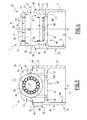
Figure 1 is a side view of a mechanical system according to the invention, of the cam follower type, comprising a tappet, a pin and a roller; -
Figure 2 is a top view, along arrow I offigure 1 ; -
Figure 3 is a sectional view along line III-III offigure 2 ; -
Figure 4 is a sectional view along line IV-IV offigure 2 ; -
Figure 5 is a perspective view showing the tappet belonging to the mechanical system offigures 1 to 4 ; -
Figure 6, 7 and 8 are perspective views similar tofigure 5 , each showing a tappet of a mechanical system according to a second, a third and a fourth embodiment of the invention, respectively. - The
mechanical system 1 represented onfigures 1 to 5 is of the cam follower type, adapted to equip an injection pump for a motor vehicle, preferably for a gasoline engine car, not shown. - The
system 1 comprises atappet 10, apin 30, aroller 40, abearing 50 and aninsert 60.Pin 30,roller 40 and bearing 50 are centered on a transverse axis X1, whiletappet 10 is centered on a longitudinal axis Y1. Axis X1 and Y1 are perpendicular. In the preferred embodiment offigures 1 to 5 , thebearing 50 consists ofneedles 52. Alternatively, it may consist of cylindrical rollers or a sliding bushing. - As shown on
figures 3 and 4 , thetappet 10 comprises a firstcylindrical portion 11, a secondcylindrical portion 12 and a centralradial portion 13 interposed betweenportions Tappet 10 also comprises abearing portion 20 extending fromportion 12opposite portions Cylindrical portion 11 has a cylindricalinner bore 16 delimiting acavity 17 inside tappet 10. Thiscavity 17 is adapted to receive a shaft, not shown, for moving tappet 10 along axis Y1.Cylindrical portion 12 delimits anothercavity 19 inside tappet 10, partly receivingpin 30,roller 40 and bearing 50.Portion 13 comprises plane surfaces 14a andcurved surfaces 14b surrounding insert 60. Fourholes 15 extend throughportion 13 parallel to axis Y1, connectingcavities Tappet 10 has a cylindricalouter surface 18, with a circular basis, centered on axis Y1 and extending along bothportions -
Tappet 10 is movable back and forth along axis Y1, in a non-represented bore belonging to the injection pump, withsurface 18 sliding in this bore.Tappet 10 can be made of synthetic material, by example polyamide 6,6 (PA) or polyether-ether-ketone (PEEK), or made of metal, by example steel. Material of thetappet 10 is chosen resistant to oil flow and temperature variations. - Furthermore,
tappet 10 forms a support element forpin 30,roller 40 andbearing 50. Specifically, bearingportion 20 oftappet 10 is adapted to receivepin 30, on whichroller 40 andbearing 50 are mounted. To this end, bearingportion 20 comprises twolateral flanges portion 12 parallel to axis Y1 in a bifurcated manner, on both side of axis Y1. Theflanges intermediate gap 23 joiningcavity 19. On the bearingportion 20, eachlateral flange flanges Bores Hollow sections portion 12, in the prolongation ofbores flange pin 30 intobores -
Pin 30 comprises acylindrical surface 32 extending between two pin ends 36 and 37. In practice, pin ends 36 and 37 are adapted to be caulked by press-fit, respectively inbores Pin 30 is made of metal, such as steel or bronze. If made of steel,pin 30 is preferably subjected to heat treatment before the caulking step. More precisely, pin ends 36 and 37 may be subjected to an electromagnetic induction heating step just before the caulking step. -
Roller 40 has an outercylindrical surface 41 and an inner cylindrical bore 42 centered on axis X1.Surface 41 is intended to bear against an outer surface of a non-represented cam, synchronized with the internal combustion engine camshaft.Surface 41 is preferably subjected to heat treatment to increase its resistance to load and/or wear. - Rolling bearing 50 comprises a series of
needles 52 extending parallel to axis X1 and distributed regularly around axis X1.Rolls 52 are interposed betweensurface 32 ofpin 30 andsurface 42 ofroller 40. - As shown on
figures 3 and 4 , insert 60 is preferably made of stamped metal sheet and assembled withtappet 10 by overmolding.Insert 60 comprises a planecentral portion 61 and twoplane lateral portions Insert 60 comprises acurved portion 64 connectingportions curved portion 65 connectingportions Curved portions curved surfaces 14b ofcentral portion 13.Insert 60 comprises a half-cylindrical section 66 which is formed onportion 62 in the prolongation ofsection 28 and which supports end 36 ofpin 30 together withbore 26.Insert 60 comprises a half-cylindrical section 67 which is formed onportion 63 in the prolongation ofsection 29 and which supports end 37 ofpin 30 together withbore 27.Central portion 61 comprises lateral plane surfaces 68 in contact withplane surfaces 14a ofcentral portion 13. -
Roller 40 and rollingbearing 50 are positioned inmechanical system 1 beforepin 30, more precisely in theintermediate gap 23 between the twoflanges tappet 10, insidesections insert 60 and inside rollingbearing 50. Finally pin ends 36 and 37 are caulked by press-fit inbores roller 40 is movable in rotation relative to pin 30 around axis X1. Pin axis, roller axis and rolling bearing axis merge with axis X1.Roller 40 is then adapted to roll, more precisely itssurface 41 can roll, on an outer surface of the non-represented cam. The load applied onsurface 41 ofroller 40 is transmitted to rollingbearing 50, then to pin 30, then to insert 60 and to bearingportion 20 oftappet 10.Insert 60 is more resistant thanflanges roller 40, in other words insert 60 increases mechanical resistance ofsystem 1. - According to the invention,
system 1 comprises anantirotation device 80 integrally formed withtappet 10, on itsouter surface 18.Device 80 is a pin protruding fromsurface 18 along a direction parallel to an axis Z1 perpendicular to axes X1 and Y1.Pin 80 has anouter surface 82 having a rounded shape in a sectional plane perpendicular to axis Y1, as shown onfigure 2 .Surface 82 cooperates with a non-represented guiding groove, formed in the bore surrounding the tappet. Thus,pin 80 preventstappet 10 from rotating in this bore around axis Y1.Pin 80 extends along axis Y1 between twoextremities extremities figures 1 to 5 ,pin 80 is closer to aperture ofcavity 19 than to aperture ofcavity 17. - Preferably,
pin 80 is moulded as one single part together withtappet 10. As an alternative,pin 80 may be formed by plastic deformation oftappet 10, for example by punching frominside cavity 17 oftappet 10, with a punch applied to bore 16 and deformingpart 11. As another alternative,pin 80 may be machined in themass tappet 10. - Others embodiments of the invention are represented on
figures 6 to 8 . Only the differences with respect to the first embodiment are described hereafter. - A second embodiment of the invention is represented on
figure 6 .Tappet 110 comprises anantirotation pin 180 which is closer to aperture ofcavity 17 than to aperture ofcavity 19. In practice, position of the antirotation pin depends on position and extent of the guiding groove formed in bore surrounding the tappet. - A third embodiment of the invention is represented on
figure 7 .Tappet 210 comprises twoantirotation pins bore surrounding tappet 210. - A fourth embodiment of the invention is represented on
figure 8 .Tappet 210 comprises anantirotation pin 380 which is a bar extending parallel to axis Y1. On the example offigure 8 ,bar 380 extends along almost 80% of the length ofouter surface 18 oftappet 310, measured parallel to axis Y1. Generally,bar 380 extends along at least 50% of the length ofouter surface 18. - Other non-shown embodiments can be implemented without leaving the scope of the invention. For example,
support element 10 and/orroller element 40 may have different configurations, by example depending on the intended application ofsystem 1. According to another example, number, shape and position of device(s) 80 may vary without leaving the scope of the invention. - According to a non-shown embodiment,
system 1 may constitute a rocker arm, wherein thesupport element 10 is not a tappet and wherein theroller element 40 is secured to an arm and a tappet, for example acting on a valve stem. - According to another non-shown embodiment,
system 1 comprises no rollingbearing 50, whilepin 30 androller 40 form together a plain bearing. Indeed, in heavy duty applications such as in diesel truck engines, there is a lack of space and/or excessive loads involved for the implementation of the rollingbearing 50, thus justifying the use of a plain bearing. Alternatively, bearing 50 may be replaced by a bushing. - According to another non-shown embodiment, insert 60 is machined then positioned inside
tappet 10. - According to another non-shown embodiment,
system 1 comprises twoantirotation devices 80 protruding fromsurface 18 and diametrically opposed relative to axis Y1. - According to another non-shown embodiment,
surface 82 may have a triangular or rectangular shape in a sectional plane perpendicular to axis Y1. - Whatever the embodiment,
system 1 comprises at least one antirotation device integrally formed with a support element such as thetappet - In addition, technical features of the different embodiments can be, in whole or part, combined with each other. Thus, the
mechanical system 1 and its manufacturing method can be adapted to the specific requirements of the application.
Claims (15)
- A mechanical system (1), comprising:- a support element (10; 110; 210; 310) defining two bores (26, 27) centered on a first axis (X1),- a pin (30) comprising two opposite ends (36, 37) each adapted to be fitted in one of the two bores (26, 27), and- a roller element (40) positioned between the two bores (26, 27) along the first axis (X1) and movable in rotation relative to the pin (30) around the first axis (X1), wherein the mechanical system (1) comprises at least one antirotation device (80; 180; 80, 180; 380) integrally formed with the support element (10; 110; 210; 310).
- The mechanical system (1) according to claim 1, wherein the antirotation device (80; 180; 80, 180; 380) is moulded with the support element (10; 110; 210; 310).
- The mechanical system (1) according to claim 1, wherein the antirotation device (80; 180; 80, 180; 380) is formed by plastic deformation of the support element (10; 110; 210; 310), for example by punching from inside the support element (10; 110; 210; 310).
- The mechanical system (1) according to claim 1, wherein the antirotation device (80; 180; 80, 180; 380) is machined in the mass of the support element (10; 110; 210; 310).
- The mechanical system (1) according to any one of the previous claims, comprising at least two antirotation devices (80; 180) integrally formed with the support element (10).
- The mechanical system (1) according to previous claim 5, wherein the two antirotation devices (80; 180) are aligned parallel to a second axis (Y1) which is perpendicular to the first axis (X1).
- The mechanical system (1) according to any one of the previous claims, wherein the antirotation device (380) is a bar extending parallel to a second axis (Y1) which is perpendicular to the first axis (X1), preferably along at least 50% of the length of an outer surface (18) of the support element (310).
- The mechanical system (1) according to any one of the previous claims, wherein the antirotation device (80; 180; 80, 180; 380) has an outer surface (82) with a curved, triangular or rectangular shape in a sectional plane perpendicular to a second axis (Y1) which is perpendicular to the first axis (X1).
- The mechanical system (1) according to any one of the previous claims 1 to 8, wherein the support element (10; 110; 210; 310) is made of synthetic material, for example of polyamide or polyether-ether-ketone.
- The mechanical system (1) according to any one of the previous claims 1 to 8, wherein the support element (10; 110; 210; 310) is made of metal, for example of steel.
- The mechanical system (1) according to any one of the previous claims, comprising a bearing (50) interposed between the pin (30) and the roller element (40).
- The mechanical system (1) according to any one of the previous claims, wherein it constitutes a cam follower, wherein the support element (10) is a tappet movable along a translation axis (Y1) perpendicular to the first axis (X1) and wherein the roller element (40) is adapted to roll on an outer surface of a cam.
- An injection pump for a motor vehicle, wherein it comprises a mechanical system (1) according to any one of claims 1 to 12.
- A valve actuator for a motor vehicle, wherein it comprises a mechanical system (1) according to any one of claims 1 to 12.
- Method for manufacturing a mechanical system (1) according to any one of claims 1 to 12, wherein the antirotation device (80; 180; 80, 180; 380) is integrally formed with the support element (10; 110; 210; 310) by moulding, stamping or machining.
Priority Applications (1)
| Application Number | Priority Date | Filing Date | Title |
|---|---|---|---|
| EP13186504.0A EP2853697B1 (en) | 2013-09-27 | 2013-09-27 | Mechanical system, injection pump and valve actuator comprising such a mechanical system and manufacturing method |
Applications Claiming Priority (1)
| Application Number | Priority Date | Filing Date | Title |
|---|---|---|---|
| EP13186504.0A EP2853697B1 (en) | 2013-09-27 | 2013-09-27 | Mechanical system, injection pump and valve actuator comprising such a mechanical system and manufacturing method |
Publications (2)
| Publication Number | Publication Date |
|---|---|
| EP2853697A1 true EP2853697A1 (en) | 2015-04-01 |
| EP2853697B1 EP2853697B1 (en) | 2016-04-27 |
Family
ID=49274467
Family Applications (1)
| Application Number | Title | Priority Date | Filing Date |
|---|---|---|---|
| EP13186504.0A Active EP2853697B1 (en) | 2013-09-27 | 2013-09-27 | Mechanical system, injection pump and valve actuator comprising such a mechanical system and manufacturing method |
Country Status (1)
| Country | Link |
|---|---|
| EP (1) | EP2853697B1 (en) |
Cited By (4)
| Publication number | Priority date | Publication date | Assignee | Title |
|---|---|---|---|---|
| CN107345491A (en) * | 2016-05-04 | 2017-11-14 | 斯凯孚公司 | Cam driven roller apparatus |
| WO2017181002A3 (en) * | 2016-04-15 | 2017-11-23 | Koyo Bearings North America Llc | Tappet with inner cup received on pallet |
| US11143059B2 (en) | 2019-10-03 | 2021-10-12 | Koyo Bearings North America Llc | Tappet assembly with unground outer cup |
| US11149593B2 (en) | 2019-10-03 | 2021-10-19 | Koyo Bearings North America Llc | Tappet assembly with formed anti-rotation alignment device |
Citations (11)
| Publication number | Priority date | Publication date | Assignee | Title |
|---|---|---|---|---|
| GB191119321A (en) * | 1910-09-09 | Leis Roman | Improvements in and relating to Ball Bearings. | |
| US3668945A (en) * | 1969-03-18 | 1972-06-13 | Bosch Gmbh Robert | Roller tappet guard |
| JP2001329809A (en) * | 2000-05-22 | 2001-11-30 | Otics Corp | Valve lifter and valve mechanism |
| WO2002020953A1 (en) * | 2000-09-09 | 2002-03-14 | Mahle Ventiltrieb Gmbh | Roller tappet for an internal combustion engine |
| US20050235932A1 (en) * | 2004-04-23 | 2005-10-27 | Albertson William C | Hybrid metal-composite valve lifter guide |
| EP1669556A1 (en) * | 2004-11-17 | 2006-06-14 | JTEKT Corporation | Rocker arm bearing |
| WO2006083102A1 (en) * | 2005-02-02 | 2006-08-10 | Seok Ki Yun | Inline skates having straight drive type joint structure |
| US7210437B2 (en) | 2004-07-24 | 2007-05-01 | Ina-Schaeffler Kg | Periodically actuable tappet for a valve train or a pump drive |
| US20080190237A1 (en) | 2006-12-06 | 2008-08-14 | Schaeffler Kg | Mechanical tappet in particular for a fuel pump of an internal combustion engine |
| WO2010048968A1 (en) | 2008-10-27 | 2010-05-06 | Ab Skf | Antirotation device |
| EP2607636A1 (en) * | 2011-12-23 | 2013-06-26 | Aktiebolaget SKF | Mechanical system, injection pump comprising such a mechanical system and method for manufacturing such a mechanical system |
-
2013
- 2013-09-27 EP EP13186504.0A patent/EP2853697B1/en active Active
Patent Citations (11)
| Publication number | Priority date | Publication date | Assignee | Title |
|---|---|---|---|---|
| GB191119321A (en) * | 1910-09-09 | Leis Roman | Improvements in and relating to Ball Bearings. | |
| US3668945A (en) * | 1969-03-18 | 1972-06-13 | Bosch Gmbh Robert | Roller tappet guard |
| JP2001329809A (en) * | 2000-05-22 | 2001-11-30 | Otics Corp | Valve lifter and valve mechanism |
| WO2002020953A1 (en) * | 2000-09-09 | 2002-03-14 | Mahle Ventiltrieb Gmbh | Roller tappet for an internal combustion engine |
| US20050235932A1 (en) * | 2004-04-23 | 2005-10-27 | Albertson William C | Hybrid metal-composite valve lifter guide |
| US7210437B2 (en) | 2004-07-24 | 2007-05-01 | Ina-Schaeffler Kg | Periodically actuable tappet for a valve train or a pump drive |
| EP1669556A1 (en) * | 2004-11-17 | 2006-06-14 | JTEKT Corporation | Rocker arm bearing |
| WO2006083102A1 (en) * | 2005-02-02 | 2006-08-10 | Seok Ki Yun | Inline skates having straight drive type joint structure |
| US20080190237A1 (en) | 2006-12-06 | 2008-08-14 | Schaeffler Kg | Mechanical tappet in particular for a fuel pump of an internal combustion engine |
| WO2010048968A1 (en) | 2008-10-27 | 2010-05-06 | Ab Skf | Antirotation device |
| EP2607636A1 (en) * | 2011-12-23 | 2013-06-26 | Aktiebolaget SKF | Mechanical system, injection pump comprising such a mechanical system and method for manufacturing such a mechanical system |
Cited By (7)
| Publication number | Priority date | Publication date | Assignee | Title |
|---|---|---|---|---|
| WO2017181002A3 (en) * | 2016-04-15 | 2017-11-23 | Koyo Bearings North America Llc | Tappet with inner cup received on pallet |
| EP3734028A1 (en) * | 2016-04-15 | 2020-11-04 | Koyo Bearings North America LLC | Tappet with inner cup received on pallet |
| US11215269B2 (en) | 2016-04-15 | 2022-01-04 | Koyo Bearings North America Llc | Tappet with inner cup received on pallet |
| CN107345491A (en) * | 2016-05-04 | 2017-11-14 | 斯凯孚公司 | Cam driven roller apparatus |
| CN107345491B (en) * | 2016-05-04 | 2021-04-16 | 斯凯孚公司 | Cam Follower Roller Equipment |
| US11143059B2 (en) | 2019-10-03 | 2021-10-12 | Koyo Bearings North America Llc | Tappet assembly with unground outer cup |
| US11149593B2 (en) | 2019-10-03 | 2021-10-19 | Koyo Bearings North America Llc | Tappet assembly with formed anti-rotation alignment device |
Also Published As
| Publication number | Publication date |
|---|---|
| EP2853697B1 (en) | 2016-04-27 |
Similar Documents
| Publication | Publication Date | Title |
|---|---|---|
| US9551408B2 (en) | Mechanical system, injection pump and valve actuator comprising such a mechanical system and manufacturing method | |
| EP2853696B1 (en) | Mechanical system, injection pump and valve actuator comprising such a mechanical system and manufacturing method | |
| EP2853698B1 (en) | Cam follower, injection pump and valve actuator comprising such a cam follower and manufacturing method | |
| EP3026232B1 (en) | Mechanical system forming a cam follower or a rocker arm, injection pump or valve actuator comprising such a mechanical system and method for manufacturing such a mechanical system | |
| US9933062B2 (en) | Mechanical system forming a cam follower or a rocker arm | |
| US10006425B2 (en) | Cam follower, injection pump and valve actuator having such a cam follower, and manufacturing method | |
| EP2853699B1 (en) | Tappet, injection pump and valve actuator comprising such a tappet and manufacturing method for such a tappet | |
| EP3026231B1 (en) | Mechanical system forming a cam follower or a rocker arm, injection pump or valve actuator comprising such a mechanical system and method for manufacturing such a mechanical system | |
| US9752670B2 (en) | Mechanical system forming a cam follower or a rocker arm | |
| EP2853697B1 (en) | Mechanical system, injection pump and valve actuator comprising such a mechanical system and manufacturing method | |
| US9745934B2 (en) | Mechanical system forming a cam follower or a rocker arm | |
| EP3085945A1 (en) | Cam follower, injection pump and valve actuator comprising such a cam follower, and manufacturing method | |
| US10385956B2 (en) | Mechanical system forming a cam follower or a rocker arm |
Legal Events
| Date | Code | Title | Description |
|---|---|---|---|
| PUAI | Public reference made under article 153(3) epc to a published international application that has entered the european phase |
Free format text: ORIGINAL CODE: 0009012 |
|
| 17P | Request for examination filed |
Effective date: 20130927 |
|
| AK | Designated contracting states |
Kind code of ref document: A1 Designated state(s): AL AT BE BG CH CY CZ DE DK EE ES FI FR GB GR HR HU IE IS IT LI LT LU LV MC MK MT NL NO PL PT RO RS SE SI SK SM TR |
|
| AX | Request for extension of the european patent |
Extension state: BA ME |
|
| R17P | Request for examination filed (corrected) |
Effective date: 20150902 |
|
| RBV | Designated contracting states (corrected) |
Designated state(s): AL AT BE BG CH CY CZ DE DK EE ES FI FR GB GR HR HU IE IS IT LI LT LU LV MC MK MT NL NO PL PT RO RS SE SI SK SM TR |
|
| RIC1 | Information provided on ipc code assigned before grant |
Ipc: F01L 1/14 20060101AFI20151001BHEP |
|
| GRAP | Despatch of communication of intention to grant a patent |
Free format text: ORIGINAL CODE: EPIDOSNIGR1 |
|
| INTG | Intention to grant announced |
Effective date: 20151106 |
|
| GRAS | Grant fee paid |
Free format text: ORIGINAL CODE: EPIDOSNIGR3 |
|
| GRAA | (expected) grant |
Free format text: ORIGINAL CODE: 0009210 |
|
| AK | Designated contracting states |
Kind code of ref document: B1 Designated state(s): AL AT BE BG CH CY CZ DE DK EE ES FI FR GB GR HR HU IE IS IT LI LT LU LV MC MK MT NL NO PL PT RO RS SE SI SK SM TR |
|
| REG | Reference to a national code |
Ref country code: GB Ref legal event code: FG4D |
|
| REG | Reference to a national code |
Ref country code: CH Ref legal event code: EP |
|
| REG | Reference to a national code |
Ref country code: AT Ref legal event code: REF Ref document number: 795052 Country of ref document: AT Kind code of ref document: T Effective date: 20160515 |
|
| REG | Reference to a national code |
Ref country code: IE Ref legal event code: FG4D |
|
| REG | Reference to a national code |
Ref country code: DE Ref legal event code: R096 Ref document number: 602013006921 Country of ref document: DE |
|
| REG | Reference to a national code |
Ref country code: LT Ref legal event code: MG4D |
|
| REG | Reference to a national code |
Ref country code: NL Ref legal event code: MP Effective date: 20160427 |
|
| REG | Reference to a national code |
Ref country code: AT Ref legal event code: MK05 Ref document number: 795052 Country of ref document: AT Kind code of ref document: T Effective date: 20160427 |
|
| REG | Reference to a national code |
Ref country code: FR Ref legal event code: PLFP Year of fee payment: 4 |
|
| PG25 | Lapsed in a contracting state [announced via postgrant information from national office to epo] |
Ref country code: NL Free format text: LAPSE BECAUSE OF FAILURE TO SUBMIT A TRANSLATION OF THE DESCRIPTION OR TO PAY THE FEE WITHIN THE PRESCRIBED TIME-LIMIT Effective date: 20160427 |
|
| PG25 | Lapsed in a contracting state [announced via postgrant information from national office to epo] |
Ref country code: FI Free format text: LAPSE BECAUSE OF FAILURE TO SUBMIT A TRANSLATION OF THE DESCRIPTION OR TO PAY THE FEE WITHIN THE PRESCRIBED TIME-LIMIT Effective date: 20160427 Ref country code: NO Free format text: LAPSE BECAUSE OF FAILURE TO SUBMIT A TRANSLATION OF THE DESCRIPTION OR TO PAY THE FEE WITHIN THE PRESCRIBED TIME-LIMIT Effective date: 20160727 Ref country code: LT Free format text: LAPSE BECAUSE OF FAILURE TO SUBMIT A TRANSLATION OF THE DESCRIPTION OR TO PAY THE FEE WITHIN THE PRESCRIBED TIME-LIMIT Effective date: 20160427 Ref country code: PL Free format text: LAPSE BECAUSE OF FAILURE TO SUBMIT A TRANSLATION OF THE DESCRIPTION OR TO PAY THE FEE WITHIN THE PRESCRIBED TIME-LIMIT Effective date: 20160427 |
|
| PG25 | Lapsed in a contracting state [announced via postgrant information from national office to epo] |
Ref country code: PT Free format text: LAPSE BECAUSE OF FAILURE TO SUBMIT A TRANSLATION OF THE DESCRIPTION OR TO PAY THE FEE WITHIN THE PRESCRIBED TIME-LIMIT Effective date: 20160829 Ref country code: ES Free format text: LAPSE BECAUSE OF FAILURE TO SUBMIT A TRANSLATION OF THE DESCRIPTION OR TO PAY THE FEE WITHIN THE PRESCRIBED TIME-LIMIT Effective date: 20160427 Ref country code: RS Free format text: LAPSE BECAUSE OF FAILURE TO SUBMIT A TRANSLATION OF THE DESCRIPTION OR TO PAY THE FEE WITHIN THE PRESCRIBED TIME-LIMIT Effective date: 20160427 Ref country code: HR Free format text: LAPSE BECAUSE OF FAILURE TO SUBMIT A TRANSLATION OF THE DESCRIPTION OR TO PAY THE FEE WITHIN THE PRESCRIBED TIME-LIMIT Effective date: 20160427 Ref country code: AT Free format text: LAPSE BECAUSE OF FAILURE TO SUBMIT A TRANSLATION OF THE DESCRIPTION OR TO PAY THE FEE WITHIN THE PRESCRIBED TIME-LIMIT Effective date: 20160427 Ref country code: LV Free format text: LAPSE BECAUSE OF FAILURE TO SUBMIT A TRANSLATION OF THE DESCRIPTION OR TO PAY THE FEE WITHIN THE PRESCRIBED TIME-LIMIT Effective date: 20160427 Ref country code: GR Free format text: LAPSE BECAUSE OF FAILURE TO SUBMIT A TRANSLATION OF THE DESCRIPTION OR TO PAY THE FEE WITHIN THE PRESCRIBED TIME-LIMIT Effective date: 20160728 Ref country code: SE Free format text: LAPSE BECAUSE OF FAILURE TO SUBMIT A TRANSLATION OF THE DESCRIPTION OR TO PAY THE FEE WITHIN THE PRESCRIBED TIME-LIMIT Effective date: 20160427 |
|
| PG25 | Lapsed in a contracting state [announced via postgrant information from national office to epo] |
Ref country code: BE Free format text: LAPSE BECAUSE OF FAILURE TO SUBMIT A TRANSLATION OF THE DESCRIPTION OR TO PAY THE FEE WITHIN THE PRESCRIBED TIME-LIMIT Effective date: 20160427 Ref country code: IT Free format text: LAPSE BECAUSE OF FAILURE TO SUBMIT A TRANSLATION OF THE DESCRIPTION OR TO PAY THE FEE WITHIN THE PRESCRIBED TIME-LIMIT Effective date: 20160427 |
|
| REG | Reference to a national code |
Ref country code: DE Ref legal event code: R097 Ref document number: 602013006921 Country of ref document: DE |
|
| PG25 | Lapsed in a contracting state [announced via postgrant information from national office to epo] |
Ref country code: EE Free format text: LAPSE BECAUSE OF FAILURE TO SUBMIT A TRANSLATION OF THE DESCRIPTION OR TO PAY THE FEE WITHIN THE PRESCRIBED TIME-LIMIT Effective date: 20160427 Ref country code: DK Free format text: LAPSE BECAUSE OF FAILURE TO SUBMIT A TRANSLATION OF THE DESCRIPTION OR TO PAY THE FEE WITHIN THE PRESCRIBED TIME-LIMIT Effective date: 20160427 Ref country code: RO Free format text: LAPSE BECAUSE OF FAILURE TO SUBMIT A TRANSLATION OF THE DESCRIPTION OR TO PAY THE FEE WITHIN THE PRESCRIBED TIME-LIMIT Effective date: 20160427 Ref country code: SK Free format text: LAPSE BECAUSE OF FAILURE TO SUBMIT A TRANSLATION OF THE DESCRIPTION OR TO PAY THE FEE WITHIN THE PRESCRIBED TIME-LIMIT Effective date: 20160427 Ref country code: CZ Free format text: LAPSE BECAUSE OF FAILURE TO SUBMIT A TRANSLATION OF THE DESCRIPTION OR TO PAY THE FEE WITHIN THE PRESCRIBED TIME-LIMIT Effective date: 20160427 |
|
| PG25 | Lapsed in a contracting state [announced via postgrant information from national office to epo] |
Ref country code: SM Free format text: LAPSE BECAUSE OF FAILURE TO SUBMIT A TRANSLATION OF THE DESCRIPTION OR TO PAY THE FEE WITHIN THE PRESCRIBED TIME-LIMIT Effective date: 20160427 |
|
| PLBE | No opposition filed within time limit |
Free format text: ORIGINAL CODE: 0009261 |
|
| STAA | Information on the status of an ep patent application or granted ep patent |
Free format text: STATUS: NO OPPOSITION FILED WITHIN TIME LIMIT |
|
| 26N | No opposition filed |
Effective date: 20170130 |
|
| PG25 | Lapsed in a contracting state [announced via postgrant information from national office to epo] |
Ref country code: MC Free format text: LAPSE BECAUSE OF FAILURE TO SUBMIT A TRANSLATION OF THE DESCRIPTION OR TO PAY THE FEE WITHIN THE PRESCRIBED TIME-LIMIT Effective date: 20160427 |
|
| REG | Reference to a national code |
Ref country code: CH Ref legal event code: PL |
|
| PG25 | Lapsed in a contracting state [announced via postgrant information from national office to epo] |
Ref country code: SI Free format text: LAPSE BECAUSE OF FAILURE TO SUBMIT A TRANSLATION OF THE DESCRIPTION OR TO PAY THE FEE WITHIN THE PRESCRIBED TIME-LIMIT Effective date: 20160427 |
|
| REG | Reference to a national code |
Ref country code: IE Ref legal event code: MM4A |
|
| PG25 | Lapsed in a contracting state [announced via postgrant information from national office to epo] |
Ref country code: LI Free format text: LAPSE BECAUSE OF NON-PAYMENT OF DUE FEES Effective date: 20160930 Ref country code: IE Free format text: LAPSE BECAUSE OF NON-PAYMENT OF DUE FEES Effective date: 20160927 Ref country code: CH Free format text: LAPSE BECAUSE OF NON-PAYMENT OF DUE FEES Effective date: 20160930 |
|
| PG25 | Lapsed in a contracting state [announced via postgrant information from national office to epo] |
Ref country code: LU Free format text: LAPSE BECAUSE OF NON-PAYMENT OF DUE FEES Effective date: 20160927 |
|
| REG | Reference to a national code |
Ref country code: FR Ref legal event code: PLFP Year of fee payment: 5 |
|
| GBPC | Gb: european patent ceased through non-payment of renewal fee |
Effective date: 20170927 |
|
| PG25 | Lapsed in a contracting state [announced via postgrant information from national office to epo] |
Ref country code: HU Free format text: LAPSE BECAUSE OF FAILURE TO SUBMIT A TRANSLATION OF THE DESCRIPTION OR TO PAY THE FEE WITHIN THE PRESCRIBED TIME-LIMIT; INVALID AB INITIO Effective date: 20130927 |
|
| PG25 | Lapsed in a contracting state [announced via postgrant information from national office to epo] |
Ref country code: IS Free format text: LAPSE BECAUSE OF FAILURE TO SUBMIT A TRANSLATION OF THE DESCRIPTION OR TO PAY THE FEE WITHIN THE PRESCRIBED TIME-LIMIT Effective date: 20160427 Ref country code: MT Free format text: LAPSE BECAUSE OF NON-PAYMENT OF DUE FEES Effective date: 20160930 Ref country code: MK Free format text: LAPSE BECAUSE OF FAILURE TO SUBMIT A TRANSLATION OF THE DESCRIPTION OR TO PAY THE FEE WITHIN THE PRESCRIBED TIME-LIMIT Effective date: 20160427 Ref country code: CY Free format text: LAPSE BECAUSE OF FAILURE TO SUBMIT A TRANSLATION OF THE DESCRIPTION OR TO PAY THE FEE WITHIN THE PRESCRIBED TIME-LIMIT Effective date: 20160427 |
|
| PG25 | Lapsed in a contracting state [announced via postgrant information from national office to epo] |
Ref country code: GB Free format text: LAPSE BECAUSE OF NON-PAYMENT OF DUE FEES Effective date: 20170927 Ref country code: BG Free format text: LAPSE BECAUSE OF FAILURE TO SUBMIT A TRANSLATION OF THE DESCRIPTION OR TO PAY THE FEE WITHIN THE PRESCRIBED TIME-LIMIT Effective date: 20160427 |
|
| REG | Reference to a national code |
Ref country code: FR Ref legal event code: PLFP Year of fee payment: 6 |
|
| PG25 | Lapsed in a contracting state [announced via postgrant information from national office to epo] |
Ref country code: TR Free format text: LAPSE BECAUSE OF FAILURE TO SUBMIT A TRANSLATION OF THE DESCRIPTION OR TO PAY THE FEE WITHIN THE PRESCRIBED TIME-LIMIT Effective date: 20160427 Ref country code: AL Free format text: LAPSE BECAUSE OF FAILURE TO SUBMIT A TRANSLATION OF THE DESCRIPTION OR TO PAY THE FEE WITHIN THE PRESCRIBED TIME-LIMIT Effective date: 20160427 |
|
| P01 | Opt-out of the competence of the unified patent court (upc) registered |
Effective date: 20230513 |
|
| PGFP | Annual fee paid to national office [announced via postgrant information from national office to epo] |
Ref country code: FR Payment date: 20240925 Year of fee payment: 12 |
|
| PGFP | Annual fee paid to national office [announced via postgrant information from national office to epo] |
Ref country code: DE Payment date: 20250926 Year of fee payment: 13 |
|
| REG | Reference to a national code |
Ref country code: DE Ref legal event code: R082 Ref document number: 602013006921 Country of ref document: DE Representative=s name: SCHONECKE, MITJA, DIPL.-PHYS. DR. RER. NAT., DE Ref country code: DE Ref legal event code: R082 Ref document number: 602013006921 Country of ref document: DE Representative=s name: SCHONECKE, MITJA, DR., DE |
|
| REG | Reference to a national code |
Ref country code: DE Ref legal event code: R082 Ref document number: 602013006921 Country of ref document: DE Representative=s name: SCHONECKE, MITJA, DR., DE |