EP2853483A2 - Erosion shield, method of fabricating a shield, and method of fabricating an article having a shield - Google Patents
Erosion shield, method of fabricating a shield, and method of fabricating an article having a shield Download PDFInfo
- Publication number
- EP2853483A2 EP2853483A2 EP14185114.7A EP14185114A EP2853483A2 EP 2853483 A2 EP2853483 A2 EP 2853483A2 EP 14185114 A EP14185114 A EP 14185114A EP 2853483 A2 EP2853483 A2 EP 2853483A2
- Authority
- EP
- European Patent Office
- Prior art keywords
- shield
- erosion
- net shape
- base
- turbine component
- Prior art date
- Legal status (The legal status is an assumption and is not a legal conclusion. Google has not performed a legal analysis and makes no representation as to the accuracy of the status listed.)
- Withdrawn
Links
Images


Classifications
-
- F—MECHANICAL ENGINEERING; LIGHTING; HEATING; WEAPONS; BLASTING
- F01—MACHINES OR ENGINES IN GENERAL; ENGINE PLANTS IN GENERAL; STEAM ENGINES
- F01D—NON-POSITIVE DISPLACEMENT MACHINES OR ENGINES, e.g. STEAM TURBINES
- F01D5/00—Blades; Blade-carrying members; Heating, heat-insulating, cooling or antivibration means on the blades or the members
- F01D5/12—Blades
- F01D5/28—Selecting particular materials; Particular measures relating thereto; Measures against erosion or corrosion
-
- B—PERFORMING OPERATIONS; TRANSPORTING
- B23—MACHINE TOOLS; METAL-WORKING NOT OTHERWISE PROVIDED FOR
- B23P—METAL-WORKING NOT OTHERWISE PROVIDED FOR; COMBINED OPERATIONS; UNIVERSAL MACHINE TOOLS
- B23P15/00—Making specific metal objects by operations not covered by a single other subclass or a group in this subclass
- B23P15/04—Making specific metal objects by operations not covered by a single other subclass or a group in this subclass turbine or like blades from several pieces
-
- F—MECHANICAL ENGINEERING; LIGHTING; HEATING; WEAPONS; BLASTING
- F01—MACHINES OR ENGINES IN GENERAL; ENGINE PLANTS IN GENERAL; STEAM ENGINES
- F01D—NON-POSITIVE DISPLACEMENT MACHINES OR ENGINES, e.g. STEAM TURBINES
- F01D5/00—Blades; Blade-carrying members; Heating, heat-insulating, cooling or antivibration means on the blades or the members
- F01D5/12—Blades
- F01D5/14—Form or construction
-
- F—MECHANICAL ENGINEERING; LIGHTING; HEATING; WEAPONS; BLASTING
- F01—MACHINES OR ENGINES IN GENERAL; ENGINE PLANTS IN GENERAL; STEAM ENGINES
- F01D—NON-POSITIVE DISPLACEMENT MACHINES OR ENGINES, e.g. STEAM TURBINES
- F01D5/00—Blades; Blade-carrying members; Heating, heat-insulating, cooling or antivibration means on the blades or the members
- F01D5/12—Blades
- F01D5/28—Selecting particular materials; Particular measures relating thereto; Measures against erosion or corrosion
- F01D5/286—Particular treatment of blades, e.g. to increase durability or resistance against corrosion or erosion
-
- F—MECHANICAL ENGINEERING; LIGHTING; HEATING; WEAPONS; BLASTING
- F01—MACHINES OR ENGINES IN GENERAL; ENGINE PLANTS IN GENERAL; STEAM ENGINES
- F01D—NON-POSITIVE DISPLACEMENT MACHINES OR ENGINES, e.g. STEAM TURBINES
- F01D5/00—Blades; Blade-carrying members; Heating, heat-insulating, cooling or antivibration means on the blades or the members
- F01D5/12—Blades
- F01D5/28—Selecting particular materials; Particular measures relating thereto; Measures against erosion or corrosion
- F01D5/288—Protective coatings for blades
-
- F—MECHANICAL ENGINEERING; LIGHTING; HEATING; WEAPONS; BLASTING
- F05—INDEXING SCHEMES RELATING TO ENGINES OR PUMPS IN VARIOUS SUBCLASSES OF CLASSES F01-F04
- F05D—INDEXING SCHEME FOR ASPECTS RELATING TO NON-POSITIVE-DISPLACEMENT MACHINES OR ENGINES, GAS-TURBINES OR JET-PROPULSION PLANTS
- F05D2230/00—Manufacture
- F05D2230/20—Manufacture essentially without removing material
-
- F—MECHANICAL ENGINEERING; LIGHTING; HEATING; WEAPONS; BLASTING
- F05—INDEXING SCHEMES RELATING TO ENGINES OR PUMPS IN VARIOUS SUBCLASSES OF CLASSES F01-F04
- F05D—INDEXING SCHEME FOR ASPECTS RELATING TO NON-POSITIVE-DISPLACEMENT MACHINES OR ENGINES, GAS-TURBINES OR JET-PROPULSION PLANTS
- F05D2230/00—Manufacture
- F05D2230/60—Assembly methods
-
- F—MECHANICAL ENGINEERING; LIGHTING; HEATING; WEAPONS; BLASTING
- F05—INDEXING SCHEMES RELATING TO ENGINES OR PUMPS IN VARIOUS SUBCLASSES OF CLASSES F01-F04
- F05D—INDEXING SCHEME FOR ASPECTS RELATING TO NON-POSITIVE-DISPLACEMENT MACHINES OR ENGINES, GAS-TURBINES OR JET-PROPULSION PLANTS
- F05D2300/00—Materials; Properties thereof
- F05D2300/10—Metals, alloys or intermetallic compounds
- F05D2300/13—Refractory metals, i.e. Ti, V, Cr, Zr, Nb, Mo, Hf, Ta, W
- F05D2300/132—Chromium
-
- F—MECHANICAL ENGINEERING; LIGHTING; HEATING; WEAPONS; BLASTING
- F05—INDEXING SCHEMES RELATING TO ENGINES OR PUMPS IN VARIOUS SUBCLASSES OF CLASSES F01-F04
- F05D—INDEXING SCHEME FOR ASPECTS RELATING TO NON-POSITIVE-DISPLACEMENT MACHINES OR ENGINES, GAS-TURBINES OR JET-PROPULSION PLANTS
- F05D2300/00—Materials; Properties thereof
- F05D2300/10—Metals, alloys or intermetallic compounds
- F05D2300/17—Alloys
- F05D2300/175—Superalloys
-
- F—MECHANICAL ENGINEERING; LIGHTING; HEATING; WEAPONS; BLASTING
- F05—INDEXING SCHEMES RELATING TO ENGINES OR PUMPS IN VARIOUS SUBCLASSES OF CLASSES F01-F04
- F05D—INDEXING SCHEME FOR ASPECTS RELATING TO NON-POSITIVE-DISPLACEMENT MACHINES OR ENGINES, GAS-TURBINES OR JET-PROPULSION PLANTS
- F05D2300/00—Materials; Properties thereof
- F05D2300/20—Oxide or non-oxide ceramics
- F05D2300/22—Non-oxide ceramics
- F05D2300/226—Carbides
-
- Y—GENERAL TAGGING OF NEW TECHNOLOGICAL DEVELOPMENTS; GENERAL TAGGING OF CROSS-SECTIONAL TECHNOLOGIES SPANNING OVER SEVERAL SECTIONS OF THE IPC; TECHNICAL SUBJECTS COVERED BY FORMER USPC CROSS-REFERENCE ART COLLECTIONS [XRACs] AND DIGESTS
- Y10—TECHNICAL SUBJECTS COVERED BY FORMER USPC
- Y10T—TECHNICAL SUBJECTS COVERED BY FORMER US CLASSIFICATION
- Y10T29/00—Metal working
- Y10T29/49—Method of mechanical manufacture
- Y10T29/49229—Prime mover or fluid pump making
Definitions
- the present invention is directed to erosion shields, methods of fabricating shields, and methods of fabricating articles having shields. More specifically, the present invention is directed to laser aided manufacturing of shields and articles having shields.
- Components in power generation systems such as the turbine rotor blades and the turbine stator blades, are used in turbine equipment and are often exposed to erosive environments.
- the erosive environment may result in component erosion caused by, for example, water droplets in steam turbines and/or by fine dust from oxide scale.
- water droplets can cause erosion of rear-stage turbine blades, where such water droplets are mixed with the steam for turbine driving. Erosion of turbine blades is problematic because it results in blade thinning and fatigue breakdown of the blade brought about by erosion.
- One method of reducing erosion of the turbine blade from water droplets includes low heat-input build-up welding to build-up a plurality of single layers on the turbine component.
- Known build-up welding techniques take a significant amount of time to produce the desired erosion protection portion.
- Another problem with using such build-up techniques is that the erosion portion must also be machined after formation to the desired blade geometry, increasing processing steps and time in manufacturing, thereby increasing costs.
- an erosion shield for example, including a cobalt chromium alloy formulated for wear resistance (e.g. STELLITE®).
- the erosion shield is secured to the turbine component and protects the component from erosion.
- Materials for such erosion shields are provided in wrought condition, requiring processing and/or machining to achieve desired sizes and/or geometries. Such processing and/or machining is especially expensive for complex shapes, such as turbine blades or airfoils.
- a process or producing or fabricating a shield, a process of fabricating an article having the shield, and an erosion shield that do not suffer from one or more of the above drawbacks would be desirable in the art.
- a method of fabricating a near-net shape erosion shield includes providing a base, positioning an energy source relative to the base, and depositing at least one wear resistant material over the base with an energy beam from the energy source.
- the at least one wear resistant material deposited over the base forms the near-net shape erosion shield configured to be positioned on a turbine component.
- a method of forming a shielded article includes providing a base, positioning an energy source relative to the base, depositing at least one wear resistant material over the base with an energy beam from the energy source to form a near-net shape erosion shield, removing the base, and securing the near-net shape erosion shield to a turbine component.
- a near-net shape erosion shield in another exemplary embodiment, includes a near-net shape erosion-resistant portion.
- the near-net shape erosion shield being configured to be positioned on a turbine component.
- Embodiments of the present disclosure in comparison to processes and articles not using one or more of the features disclosed herein, increase efficiency, decrease cost, increase ease of manufacturing, increase flexibility of manufacturing, decrease set-up time, permit blending of alloys in a single process, or a combination thereof.
- FIG. 1 represents an embodiment of a fabrication process 100 for fabricating a near-net shape erosion shield 101.
- the fabrication process 100 includes providing a base 109 (step 110), positioning an energy source 107 (step 120) relative to the base 109, and depositing at least one material 103 (step 130) over the base 109 with an energy beam 105 from the energy source 107.
- Depositing (step 130) of the at least one material 103 forms a shield 101 having a net or near-net shape configured to be positioned on a turbine component 201 ( FIG. 2 ).
- the phrase "near-net” refers to being of a geometry and size requiring little or no machining and processing.
- the phrase “net” refers to being of a geometry and size requiring no machining and processing.
- the fabrication process 100 includes removing the shield 101 from the base 109.
- the base is any suitable base including, but not limited to, a sacrificial base, a composition similar to the turbine component 201, or a combination thereof.
- Further embodiments include heat treating the shield 101, and/or finishing of the shield 101, for example, by machining, sanding, grit-blasting, cutting, treating, coating, or a combination thereof. Alternate embodiments are devoid of finishing and/or machining, sanding, grit-blasting, cutting, treating, coating, or a combination thereof.
- the material 103 is deposited (step 130) using computer rasterization and/or laser aided manufacturing (LAM) performed in a non-oxidizing environment such as, but not limited to, a vacuum chamber, a shielding gas, or a combination thereof.
- the LAM is performed by any suitable energy beam 105 from the energy source 107. Suitable energy beams include, but are not limited to, a laser beam, an electron beam, a plasma beam, an electric arc, or a combination thereof.
- the LAM includes layer by layer deposition (step 130) of the material 103, permitting formation of the shield 101 having net or near-net shape over the base 109 having a planar or substantially-planar configuration.
- the LAM permits any suitable variation of the material 103 during the layer by layer deposition (step 130) to create layers of differing composition within the shield 101.
- Suitable variations of the material 103 include, but are not limited to, compositional variations among layers, compositional variations within layers, or a combination thereof.
- the material 103 is varied to form the shield 101 having a shim portion 113 integral with an erosion-resistant portion 111, the shim portion 113 and erosion-resistant portion 111 having different compositions and different material properties.
- the material 103 is varied to form the shield 101 having differing sections within the shim portion 113 and/or the erosion-resistant portion 111.
- a method of forming a shielded article 200 includes securing (step 210) the shield 101 to the substrate 203 of any suitable turbine component 201 capable of being protected by the shield 101.
- suitable turbine components capable of being protected by the shield 101 include, but are not limited to, one or more of a blade or airfoil, a nozzle, a valve, a diaphragm, a bucket, or a rotor.
- the shield 101 is secured (step 210) to a pressure side of a leading edge portion of the bucket.
- an existing shield is removed from the turbine component 201 and replaced by a new shield formed by the fabrication process 100.
- the shield 101 is secured (step 210) by any suitable technique including, but not limited to, brazing, laser welding, electron beam welding, plasma welding, tungsten inert gas welding, metal inert gas (MIG) welding, or a combination thereof.
- the shield 101 includes the erosion-resistant portion 111 and is secured (step 210) directly to the substrate 203.
- the shim portion 113 facilitates the securing (step 210) of the shield 101 to the substrate 203.
- the shim portion 113 may be integral with the erosion-resistant portion 111, or formed from a wrought shim material and mechanically fit to the erosion-resistant portion 111. Additionally, the shim portion 113 that is formed from a wrought shim material may be positioned between the erosion-resistant portion 111 and the substrate 203 or attached to the erosion-resistant portion 111 prior to securing (step 210) of the shield 101.
- the shim portion 113 includes any suitable composition capable of securing (step 210) the shield 101 to the substrate 203 of the turbine component 201 and survivable in the turbine environment.
- the substrate 203 is composed of material selected from the group including, but not limited to, an iron-based or nickel-based alloy, a 12-chrome material, 410 stainless steel (UNS S41000), 403 stainless steel (UNS S40300), GTD-450TM (a precipitation-hardened steel having a nominal composition of 15.5% Cr, 6.3% Ni, 1.5% Cu, 0.37% Nb, 0.05% C, and the balance essentially Fe), or a combination thereof.
- One suitable alloy has a composition, by weight, of about 0.15% carbon, about 1.00% manganese, about 0.50% silicon, between about 11.5% and about 13.0% chromium, about 0.04% phosphorus, about 0.03% sulfur, and a balance of iron.
- Another suitable alloy has a composition, by weight, of about 0.14% carbon, about 0.80% manganese, about 0.015% phosphorous, about 0.010% sulfur, about 0.2% silicon, about 11.5% chromium, about 2.5% nickel, about 1.6% molybdenum about 0.3% vanadium, about 0.03% nitrogen and a balance of iron.
- Another suitable alloy has a composition, by weight, of about 0.050% carbon, between about 14.0% and about 16.0% chromium, between about 1.25% and about 1.75% copper, about 1.0% manganese, between about 0.50% and about 1.0% molybdenum, between about 5.0% and about 7.0% nickel, about 0.30% phosphorus, about 1.0% silicon, about 0.030% sulfur, and a balance of iron.
- Suitable compositions of the shim portion 113 include, but are not limited to, Inconel, nickel-based alloy such as Inconel, alloy 600, or a combination thereof.
- the shim portion 113 is any suitable thickness capable of conferring desired properties.
- the thickness of the shim portion 113 is selected to provide a sufficient transition between a substrate 203 of the turbine component 201 and the erosion-resistant portion 111, thereby reducing or eliminating delamination, fatigue, welding difficulties, crack propagation, and/or other undesirable effects.
- the shim portion 113 provides a physical barrier limiting carbon migration between the substrate 203 and higher carbon material in the erosion-resistant portion 111, thereby reducing or eliminating weakening of a weld or heat affected zone.
- Suitable thicknesses of the shim portion 113 include, but are not limited to, between about 10 mils and about 200 mils, between about 50 mils and about 200 mils, between about 100 mils and about 200 mils, between about 150 mils and about 200 mils, between about 50 mils and about 150 mils, between about 100 mils and about 150 mils, between about 10 mils and about 100 mils, between about 50 mils and about 100 mils, between about 10 mils and about 50 mils, between about 10 mils and about 20 mils, or any suitable combination, sub-combination, range, or sub-range thereof, wherein 1 mil is equal to 0.001 inches.
- the erosion-resistant portion 111 includes any suitable composition for reducing or eliminating erosion of the turbine component 201. Suitable compositions of the erosion-resistant portion 111 include, but are not limited to, cobalt-based alloys, chromium-based alloys, tungsten-based alloy, chromium carbide materials, or combinations thereof. In one embodiment, the composition of the erosion-resistant portion 111 is a member of the STELLITE® family of alloys. For example, in one embodiment, the erosion-resistant portion 111 has a nominal composition, in weight percent, of between about 27 percent and about 32 percent chromium, between about 4 percent and about 6 percent tungsten, between about 0.9 percent and about 1.4 percent carbon, and a balance of cobalt and incidental impurities.
- the erosion-resistant portion 111 has a nominal composition, in weight percent, of between about 1.4 percent and about 1.85 percent carbon, about 29.5 percent chromium, about 1.5 percent silicon, about 8.5 percent tungsten, and a balance of cobalt and incidental impurities.
- the erosion-resistant portion 111 is any suitable thickness conferring desired properties of erosion resistance, wear resistance, and survivability in a steam or gas turbine environment.
- the thickness of the erosion-resistant portion 111 is selected to confer a sufficient wear resistance and/or erosion-resistance, for example, over a predetermined life of a specific component/use.
- Suitable thicknesses of the erosion-resistant portion 111 include, but are not limited to, between about 200 mils and about 500 mils, between about 300 mils and about 500 mils, between about 400 mils and about 500 mils, between about 200 mils and about 400 mils, between about 300 mils and about 400 mils, between about 200 mils and about 300 mils, or any suitable combination, sub-combination, range, or sub-range thereof.
- the shim portion 113 and/or the erosion-resistant portion 111 form the shield 101 having any suitable thickness and/or width for protecting the turbine component 201.
- Suitable thicknesses and/or widths include, but are not limited to, between about 500 mils and about 750 mils, up to about 750 mils, up to about 500 mils, or any combination, sub-combination, range, or sub-range thereof.
- the shield 101 is any suitable length capable of protecting the substrate 203 of the turbine component 201 from erosion.
- a suitable length includes, but is not limited to, a full length of the bucket, about 2/3 the length of the bucket, or about 1/3 the length of the bucket, wherein the bucket length is between about 4 inches and about 70 inches, between about 6 inches and about 20 inches, or any combination, sub-combination, range, or sub-range thereof.
- the shield 101 includes any suitable geometric features capable of being formed by use of the energy beam 105. Suitable geometric features include, but are not limited to, cavities, non-parallel surfaces, round/curved surfaces, angled surfaces, protrusions, gaps, or other difficult to form shapes/geometries. In one embodiment, the geometric features of the shield 101 substantially correspond or completely correspond with all or a portion of the turbine component 201 to be protected by the shield 101.
- the shield 101 includes a non-erosion-resistant portion 301 and an erosion resistant portion 111.
- the non-erosion-resistant portion 301 and erosion resistant portion 111 forming a continuous surface covering the turbine component 203 or alternatively the shim 113 overlying the turbine component 203.
- the erosion-resistant portion 111 covers about 1/3 of the shim 113 overlying the leading edge portion of the bucket and the non-erosion-resistant portion 301 covers the remaining 2/3 of the shim 113 overlying the leading edge portion of the bucket.
- the erosion-resistant portion 111 is positioned to cover and protect a distal 1/3 of the leading edge portion of the bucket where water droplets may increase corrosion of the bucket.
- the erosion-resistant portion 111 covers about 2/3 of the shim 113 overlying the leading edge portion of the bucket and the non-erosion-resistant portion 301 covers the remaining 1/3 of the shim 113 overlying the leading edge portion of the bucket.
- the erosion-resistant portion 111 is positioned to cover and protect a proximal 2/3 of the leading edge portion of the bucket where water from water washing may increase corrosion of the bucket.
Landscapes
- Engineering & Computer Science (AREA)
- Mechanical Engineering (AREA)
- General Engineering & Computer Science (AREA)
- Chemical & Material Sciences (AREA)
- Materials Engineering (AREA)
- Turbine Rotor Nozzle Sealing (AREA)
- Welding Or Cutting Using Electron Beams (AREA)
- Laser Beam Processing (AREA)
- Physical Vapour Deposition (AREA)
Abstract
Description
- The present invention is directed to erosion shields, methods of fabricating shields, and methods of fabricating articles having shields. More specifically, the present invention is directed to laser aided manufacturing of shields and articles having shields.
- Components in power generation systems, such as the turbine rotor blades and the turbine stator blades, are used in turbine equipment and are often exposed to erosive environments. The erosive environment may result in component erosion caused by, for example, water droplets in steam turbines and/or by fine dust from oxide scale. In particular, water droplets can cause erosion of rear-stage turbine blades, where such water droplets are mixed with the steam for turbine driving. Erosion of turbine blades is problematic because it results in blade thinning and fatigue breakdown of the blade brought about by erosion.
- One method of reducing erosion of the turbine blade from water droplets includes low heat-input build-up welding to build-up a plurality of single layers on the turbine component. Known build-up welding techniques take a significant amount of time to produce the desired erosion protection portion. Another problem with using such build-up techniques is that the erosion portion must also be machined after formation to the desired blade geometry, increasing processing steps and time in manufacturing, thereby increasing costs.
- Another preventative measure is to use an erosion shield, for example, including a cobalt chromium alloy formulated for wear resistance (e.g. STELLITE®). The erosion shield is secured to the turbine component and protects the component from erosion. Materials for such erosion shields are provided in wrought condition, requiring processing and/or machining to achieve desired sizes and/or geometries. Such processing and/or machining is especially expensive for complex shapes, such as turbine blades or airfoils.
- A process or producing or fabricating a shield, a process of fabricating an article having the shield, and an erosion shield that do not suffer from one or more of the above drawbacks would be desirable in the art.
- In an exemplary embodiment, a method of fabricating a near-net shape erosion shield includes providing a base, positioning an energy source relative to the base, and depositing at least one wear resistant material over the base with an energy beam from the energy source. The at least one wear resistant material deposited over the base forms the near-net shape erosion shield configured to be positioned on a turbine component.
- In another exemplary embodiment, a method of forming a shielded article includes providing a base, positioning an energy source relative to the base, depositing at least one wear resistant material over the base with an energy beam from the energy source to form a near-net shape erosion shield, removing the base, and securing the near-net shape erosion shield to a turbine component.
- In another exemplary embodiment, a near-net shape erosion shield includes a near-net shape erosion-resistant portion. The near-net shape erosion shield being configured to be positioned on a turbine component.
- Various features and advantages of the present invention will be apparent from the following more detailed description of the preferred embodiment, taken in conjunction with the accompanying drawings which illustrate, by way of example, the principles of the invention. In the drawings:
-
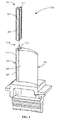
FIG. 1 is a perspective schematic view of a method of fabrication to produce a near-net shape erosion shield, according to the disclosure. -
FIG. 2 is a process view of a method of forming a shielded article, according to the disclosure. -
FIG. 3 is a perspective schematic view of a method of forming a shielded article, according to the disclosure. -
FIG. 4 is a perspective schematic view of a method of forming a shielded article, according to the disclosure. - Wherever possible, the same reference numbers will be used throughout the drawings to represent the same parts.
- Provided are a method of fabricating a near-net shape erosion shield, a method of forming a shielded article, and a near-net shape erosion shield. Embodiments of the present disclosure, in comparison to processes and articles not using one or more of the features disclosed herein, increase efficiency, decrease cost, increase ease of manufacturing, increase flexibility of manufacturing, decrease set-up time, permit blending of alloys in a single process, or a combination thereof.
-
FIG. 1 represents an embodiment of afabrication process 100 for fabricating a near-netshape erosion shield 101. Thefabrication process 100 includes providing a base 109 (step 110), positioning an energy source 107 (step 120) relative to thebase 109, and depositing at least one material 103 (step 130) over thebase 109 with anenergy beam 105 from theenergy source 107. Depositing (step 130) of the at least onematerial 103 forms ashield 101 having a net or near-net shape configured to be positioned on a turbine component 201 (FIG. 2 ). As used herein, the phrase "near-net" refers to being of a geometry and size requiring little or no machining and processing. As used herein, the phrase "net" refers to being of a geometry and size requiring no machining and processing. - In another embodiment, the
fabrication process 100 includes removing theshield 101 from thebase 109. The base is any suitable base including, but not limited to, a sacrificial base, a composition similar to theturbine component 201, or a combination thereof. Further embodiments include heat treating theshield 101, and/or finishing of theshield 101, for example, by machining, sanding, grit-blasting, cutting, treating, coating, or a combination thereof. Alternate embodiments are devoid of finishing and/or machining, sanding, grit-blasting, cutting, treating, coating, or a combination thereof. - In one embodiment, the
material 103 is deposited (step 130) using computer rasterization and/or laser aided manufacturing (LAM) performed in a non-oxidizing environment such as, but not limited to, a vacuum chamber, a shielding gas, or a combination thereof. The LAM is performed by anysuitable energy beam 105 from theenergy source 107. Suitable energy beams include, but are not limited to, a laser beam, an electron beam, a plasma beam, an electric arc, or a combination thereof. The LAM includes layer by layer deposition (step 130) of thematerial 103, permitting formation of theshield 101 having net or near-net shape over thebase 109 having a planar or substantially-planar configuration. - Additionally, the LAM permits any suitable variation of the
material 103 during the layer by layer deposition (step 130) to create layers of differing composition within theshield 101. Suitable variations of thematerial 103 include, but are not limited to, compositional variations among layers, compositional variations within layers, or a combination thereof. For example, in one embodiment, thematerial 103 is varied to form theshield 101 having ashim portion 113 integral with an erosion-resistant portion 111, theshim portion 113 and erosion-resistant portion 111 having different compositions and different material properties. In another embodiment, thematerial 103 is varied to form theshield 101 having differing sections within theshim portion 113 and/or the erosion-resistant portion 111. - Referring to
FIGS. 2-3 , in one embodiment, a method of forming a shieldedarticle 200 includes securing (step 210) theshield 101 to thesubstrate 203 of anysuitable turbine component 201 capable of being protected by theshield 101. Suitable turbine components capable of being protected by theshield 101 include, but are not limited to, one or more of a blade or airfoil, a nozzle, a valve, a diaphragm, a bucket, or a rotor. In another embodiment, theshield 101 is secured (step 210) to a pressure side of a leading edge portion of the bucket. In yet another embodiment, an existing shield is removed from theturbine component 201 and replaced by a new shield formed by thefabrication process 100. - The
shield 101 is secured (step 210) by any suitable technique including, but not limited to, brazing, laser welding, electron beam welding, plasma welding, tungsten inert gas welding, metal inert gas (MIG) welding, or a combination thereof. In one embodiment, theshield 101 includes the erosion-resistant portion 111 and is secured (step 210) directly to thesubstrate 203. In another embodiment, theshim portion 113 facilitates the securing (step 210) of theshield 101 to thesubstrate 203. Theshim portion 113 may be integral with the erosion-resistant portion 111, or formed from a wrought shim material and mechanically fit to the erosion-resistant portion 111. Additionally, theshim portion 113 that is formed from a wrought shim material may be positioned between the erosion-resistant portion 111 and thesubstrate 203 or attached to the erosion-resistant portion 111 prior to securing (step 210) of theshield 101. - The
shim portion 113 includes any suitable composition capable of securing (step 210) theshield 101 to thesubstrate 203 of theturbine component 201 and survivable in the turbine environment. In one embodiment, thesubstrate 203 is composed of material selected from the group including, but not limited to, an iron-based or nickel-based alloy, a 12-chrome material, 410 stainless steel (UNS S41000), 403 stainless steel (UNS S40300), GTD-450™ (a precipitation-hardened steel having a nominal composition of 15.5% Cr, 6.3% Ni, 1.5% Cu, 0.37% Nb, 0.05% C, and the balance essentially Fe), or a combination thereof. The listing of materials is exemplary only, and is not intended to limit the scope of the disclosure as theshield 101 may be secured to anysubstrate 203. One suitable alloy has a composition, by weight, of about 0.15% carbon, about 1.00% manganese, about 0.50% silicon, between about 11.5% and about 13.0% chromium, about 0.04% phosphorus, about 0.03% sulfur, and a balance of iron. Another suitable alloy has a composition, by weight, of about 0.14% carbon, about 0.80% manganese, about 0.015% phosphorous, about 0.010% sulfur, about 0.2% silicon, about 11.5% chromium, about 2.5% nickel, about 1.6% molybdenum about 0.3% vanadium, about 0.03% nitrogen and a balance of iron. Another suitable alloy has a composition, by weight, of about 0.050% carbon, between about 14.0% and about 16.0% chromium, between about 1.25% and about 1.75% copper, about 1.0% manganese, between about 0.50% and about 1.0% molybdenum, between about 5.0% and about 7.0% nickel, about 0.30% phosphorus, about 1.0% silicon, about 0.030% sulfur, and a balance of iron. Suitable compositions of theshim portion 113 include, but are not limited to, Inconel, nickel-based alloy such as Inconel, alloy 600, or a combination thereof. - The
shim portion 113 is any suitable thickness capable of conferring desired properties. In one embodiment, the thickness of theshim portion 113 is selected to provide a sufficient transition between asubstrate 203 of theturbine component 201 and the erosion-resistant portion 111, thereby reducing or eliminating delamination, fatigue, welding difficulties, crack propagation, and/or other undesirable effects. For example, in one embodiment, theshim portion 113 provides a physical barrier limiting carbon migration between thesubstrate 203 and higher carbon material in the erosion-resistant portion 111, thereby reducing or eliminating weakening of a weld or heat affected zone. Suitable thicknesses of theshim portion 113 include, but are not limited to, between about 10 mils and about 200 mils, between about 50 mils and about 200 mils, between about 100 mils and about 200 mils, between about 150 mils and about 200 mils, between about 50 mils and about 150 mils, between about 100 mils and about 150 mils, between about 10 mils and about 100 mils, between about 50 mils and about 100 mils, between about 10 mils and about 50 mils, between about 10 mils and about 20 mils, or any suitable combination, sub-combination, range, or sub-range thereof, wherein 1 mil is equal to 0.001 inches. - The erosion-
resistant portion 111 includes any suitable composition for reducing or eliminating erosion of theturbine component 201. Suitable compositions of the erosion-resistant portion 111 include, but are not limited to, cobalt-based alloys, chromium-based alloys, tungsten-based alloy, chromium carbide materials, or combinations thereof. In one embodiment, the composition of the erosion-resistant portion 111 is a member of the STELLITE® family of alloys. For example, in one embodiment, the erosion-resistant portion 111 has a nominal composition, in weight percent, of between about 27 percent and about 32 percent chromium, between about 4 percent and about 6 percent tungsten, between about 0.9 percent and about 1.4 percent carbon, and a balance of cobalt and incidental impurities. In another example, the erosion-resistant portion 111 has a nominal composition, in weight percent, of between about 1.4 percent and about 1.85 percent carbon, about 29.5 percent chromium, about 1.5 percent silicon, about 8.5 percent tungsten, and a balance of cobalt and incidental impurities. - The erosion-
resistant portion 111 is any suitable thickness conferring desired properties of erosion resistance, wear resistance, and survivability in a steam or gas turbine environment. In one embodiment, the thickness of the erosion-resistant portion 111 is selected to confer a sufficient wear resistance and/or erosion-resistance, for example, over a predetermined life of a specific component/use. Suitable thicknesses of the erosion-resistant portion 111 include, but are not limited to, between about 200 mils and about 500 mils, between about 300 mils and about 500 mils, between about 400 mils and about 500 mils, between about 200 mils and about 400 mils, between about 300 mils and about 400 mils, between about 200 mils and about 300 mils, or any suitable combination, sub-combination, range, or sub-range thereof. - Together, the
shim portion 113 and/or the erosion-resistant portion 111 form theshield 101 having any suitable thickness and/or width for protecting theturbine component 201. Suitable thicknesses and/or widths include, but are not limited to, between about 500 mils and about 750 mils, up to about 750 mils, up to about 500 mils, or any combination, sub-combination, range, or sub-range thereof. - The
shield 101 is any suitable length capable of protecting thesubstrate 203 of theturbine component 201 from erosion. A suitable length includes, but is not limited to, a full length of the bucket, about 2/3 the length of the bucket, or about 1/3 the length of the bucket, wherein the bucket length is between about 4 inches and about 70 inches, between about 6 inches and about 20 inches, or any combination, sub-combination, range, or sub-range thereof. - Additionally, the
shield 101 includes any suitable geometric features capable of being formed by use of theenergy beam 105. Suitable geometric features include, but are not limited to, cavities, non-parallel surfaces, round/curved surfaces, angled surfaces, protrusions, gaps, or other difficult to form shapes/geometries. In one embodiment, the geometric features of theshield 101 substantially correspond or completely correspond with all or a portion of theturbine component 201 to be protected by theshield 101. - Referring to
FIG. 4 , in one embodiment, theshield 101 includes a non-erosion-resistant portion 301 and an erosionresistant portion 111. The non-erosion-resistant portion 301 and erosionresistant portion 111 forming a continuous surface covering theturbine component 203 or alternatively theshim 113 overlying theturbine component 203. Referring toFIG. 4 , in another embodiment, the erosion-resistant portion 111 covers about 1/3 of theshim 113 overlying the leading edge portion of the bucket and the non-erosion-resistant portion 301 covers the remaining 2/3 of theshim 113 overlying the leading edge portion of the bucket. For example, in the steam turbine the erosion-resistant portion 111 is positioned to cover and protect a distal 1/3 of the leading edge portion of the bucket where water droplets may increase corrosion of the bucket. In an alternate embodiment, the erosion-resistant portion 111 covers about 2/3 of theshim 113 overlying the leading edge portion of the bucket and the non-erosion-resistant portion 301 covers the remaining 1/3 of theshim 113 overlying the leading edge portion of the bucket. For example, in the gas turbine the erosion-resistant portion 111 is positioned to cover and protect a proximal 2/3 of the leading edge portion of the bucket where water from water washing may increase corrosion of the bucket. - While the invention has been described with reference to a preferred embodiment, it will be understood by those skilled in the art that various changes may be made and equivalents may be substituted for elements thereof without departing from the scope of the invention. In addition, many modifications may be made to adapt a particular situation or material to the teachings of the invention without departing from the essential scope thereof. Therefore, it is intended that the invention not be limited to the particular embodiment disclosed as the preferred mode contemplated for carrying out this invention, but that the invention will include all embodiments falling within the scope of the appended claims.
- Various aspects and embodiments of the present invention are defined by the following numbered clauses:
- 1. A method of fabricating a near-net shape erosion shield, comprising:
- providing a base;
- positioning an energy source relative to the base; and
- depositing at least one wear resistant material over the base with an energy beam from the energy source;
- wherein the at least one wear resistant material deposited over the base forms the near-net shape erosion shield configured to be positioned on a turbine component.
- 2. The method of clause 1, comprising depositing a shim over the base with the energy beam prior to depositing the at least one wear resistant material to form the near-net shape erosion shield having the shim integral with the at least one wear resistant material.
- 3. The method of any preceding clause, comprising removing the near-net shape erosion shield from the base.
- 4. The method of any preceding clause, wherein the base is a sacrificial layer.
- 5. The method of any preceding clause, comprising selecting the energy beam from the group consisting of a laser, an electron beam, a plasma beam, and an electric arc.
- 6. The method of any preceding clause, further comprising depositing multiple layers of the at least one wear resistant material over the base.
- 7. A method of forming a shielded article, comprising:
- providing a base;
- positioning an energy source relative to the base;
- depositing at least one wear resistant material over the base with an energy beam from the energy source to form a near-net shape erosion shield;
- removing the base; and
- securing the near-net shape erosion shield to a turbine component.
- 8. The method of any preceding clause, comprising depositing a shim over the base prior to depositing the at least one wear resistant material over the base.
- 9. The method of any preceding clause, further comprising positioning the shim between the near-net shape erosion shield and the turbine component prior to securing the near-net shape erosion shield to the turbine component.
- 10. The method of any preceding clause, wherein the shim comprises a nickel-based alloy material.
- 11. The method of any preceding clause, further comprising securing the near-net shape erosion shield to the turbine component with a method selected from the group consisting of brazing and electron beam welding.
- 12. A near-net shape erosion shield, comprising:
- a near-net shape erosion-resistant portion;
- wherein the near-net shape erosion shield is configured to be positioned on a turbine component.
- 13. The shield of any preceding clause, wherein a composition of the near-net shape erosion-resistant portion comprises an erosion-resistant alloy.
- 14. The shield of any preceding clause, wherein the erosion-resistant alloy is selected from the group consisting of cobalt-based alloys, chromium-based alloys, tungsten-based alloy, and chromium carbide materials.
- 15. The shield of any preceding clause, comprising a shim secured to the near-net shape erosion-resistant portion, the shim configured to be positioned between the near-net shape erosion-resistant portion and the turbine component.
- 16. The shield of any preceding clause, wherein the turbine component is a turbine bucket.
- 17. The shield of any preceding clause, wherein the shield is configured to be positioned on a leading edge of the turbine bucket.
- 18. The shield of any preceding clause, wherein the shield covers at least about 1/3 of the leading edge of the turbine bucket.
- 19. The shield of any preceding clause, comprising a non-erosion-resistant portion forming a continuous surface with the erosion-resistant portion
- 20. The shield of any preceding clause, wherein the non-erosion-resistant portion covers about 2/3 of a leading edge of the turbine component.
Claims (15)
- A method (100) of fabricating a near-net shape erosion shield (101), comprising:providing (110) a base (109);positioning (120) an energy source (107) relative to the base (109); anddepositing (130) at least one wear resistant material (117) over the base (109) with an energy beam (105) from the energy source (107);wherein the at least one wear resistant material (111) deposited over the base (109) forms the near-net shape erosion shield (101) configured to be positioned on a turbine component (201).
- The method (100) of claim 1, comprising depositing a shim (113) over the base (109) with the energy beam (105) prior to depositing (130) the at least one wear resistant material to form the near-net shape erosion shield having the shim integral with the at least one wear resistant material.
- The method (100) of any preceding claim, comprising removing the near-net shape erosion shield (101) from the base (109).
- The method (100) of any preceding claim, wherein the base (109) is a sacrificial layer.
- The method (100) of any preceding claim, comprising selecting the energy beam (105) from the group consisting of a laser, an electron beam, a plasma beam, and an electric arc.
- The method (100) of any preceding claim, further comprising depositing multiple layers of the at least one wear resistant material (111) over the base (109).
- A near-net shape erosion shield (101), comprising:a near-net shape erosion-resistant portion;wherein the near-net shape erosion shield is configured to be positioned on a turbine component (201).
- The shield (101) of claim 7, wherein a composition of the near-net shape erosion-resistant portion comprises an erosion-resistant alloy.
- The shield (101) of claim 7 or claim 8, wherein the erosion-resistant alloy is selected from the group consisting of cobalt-based alloys, chromium-based alloys, tungsten-based alloy, and chromium carbide materials.
- The shield (101) of any of claims 7 to 9, comprising a shim (113) secured to the near-net shape erosion-resistant portion, the shim configured to be positioned between the near-net shape erosion-resistant portion and the turbine component.
- The shield (101) of any of claims 7 to 10, wherein the turbine component (201) is a turbine bucket.
- The shield (101) of any of claims 7 to 11, wherein the shield (101) is configured to be positioned on a leading edge of the turbine bucket.
- The shield (101) of any of claims 7 to 12, wherein the shield covers at least about 1/3 of the leading edge of the turbine bucket.
- The shield (101) of any of claims 7 to 13, comprising a non-erosion-resistant portion forming a continuous surface with the erosion-resistant portion
- The shield (101) of any of claims 7 to 14, wherein the non-erosion-resistant portion covers about 2/3 of a leading edge of the turbine component (201).
Applications Claiming Priority (1)
| Application Number | Priority Date | Filing Date | Title |
|---|---|---|---|
| US14/036,733 US9695697B2 (en) | 2013-09-25 | 2013-09-25 | Erosion shield, method of fabricating a shield, and method of fabricating an article having a shield |
Publications (2)
| Publication Number | Publication Date |
|---|---|
| EP2853483A2 true EP2853483A2 (en) | 2015-04-01 |
| EP2853483A3 EP2853483A3 (en) | 2015-05-06 |
Family
ID=51584961
Family Applications (1)
| Application Number | Title | Priority Date | Filing Date |
|---|---|---|---|
| EP20140185114 Withdrawn EP2853483A3 (en) | 2013-09-25 | 2014-09-17 | Erosion shield, method of fabricating a shield, and method of fabricating an article having a shield |
Country Status (4)
| Country | Link |
|---|---|
| US (1) | US9695697B2 (en) |
| EP (1) | EP2853483A3 (en) |
| JP (1) | JP2015078686A (en) |
| CN (1) | CN104451674A (en) |
Cited By (2)
| Publication number | Priority date | Publication date | Assignee | Title |
|---|---|---|---|---|
| GB2550860A (en) * | 2016-05-26 | 2017-12-06 | Rolls Royce Plc | Methods, apparatus, computer programs and non-transitory computer readable storage mediums for manufacturing gas shields for welding one or more articles |
| WO2021173392A1 (en) * | 2020-02-25 | 2021-09-02 | General Electric Company | Tungsten-based erosion-resistant leading edge protection cap for rotor blades |
Families Citing this family (11)
| Publication number | Priority date | Publication date | Assignee | Title |
|---|---|---|---|---|
| US9737933B2 (en) | 2012-09-28 | 2017-08-22 | General Electric Company | Process of fabricating a shield and process of preparing a component |
| US10138732B2 (en) * | 2016-06-27 | 2018-11-27 | United Technologies Corporation | Blade shield removal and replacement |
| US10502058B2 (en) | 2016-07-08 | 2019-12-10 | General Electric Company | Coupon for hot gas path component having manufacturing assist features |
| US10450868B2 (en) | 2016-07-22 | 2019-10-22 | General Electric Company | Turbine rotor blade with coupon having corrugated surface(s) |
| US10443399B2 (en) | 2016-07-22 | 2019-10-15 | General Electric Company | Turbine vane with coupon having corrugated surface(s) |
| US10408082B2 (en) * | 2016-11-17 | 2019-09-10 | United Technologies Corporation | Airfoil with retention pocket holding airfoil piece |
| US10989223B2 (en) * | 2017-02-06 | 2021-04-27 | General Electric Company | Coated flange bolt hole and methods of forming the same |
| JP6968006B2 (en) * | 2018-03-09 | 2021-11-17 | 三菱重工業株式会社 | A method for manufacturing a leading edge cover member, a leading edge cover member unit, a composite material wing, a leading edge cover member, and a method for manufacturing a composite material wing. |
| JP6735299B2 (en) * | 2018-03-09 | 2020-08-05 | 三菱重工業株式会社 | Composite blade, leading edge metal cover forming unit, method for manufacturing composite blade |
| US12571311B2 (en) | 2022-10-25 | 2026-03-10 | General Electric Company | Erosion-shielded turbine blades and methods of manufacturing the same |
| US12129769B2 (en) | 2022-10-25 | 2024-10-29 | Ge Infrastructure Technology Llc | Erosion-shielded turbine blades and methods of manufacturing the same |
Family Cites Families (13)
| Publication number | Priority date | Publication date | Assignee | Title |
|---|---|---|---|---|
| US4152816A (en) * | 1977-06-06 | 1979-05-08 | General Motors Corporation | Method of manufacturing a hybrid turbine rotor |
| US5160822A (en) | 1991-05-14 | 1992-11-03 | General Electric Company | Method for depositing material on the tip of a gas turbine engine airfoil using linear translational welding |
| JPH0523920A (en) * | 1991-07-19 | 1993-02-02 | Hitachi Ltd | Method of joining anti-corrosion piece of turbine blade |
| US5900170A (en) * | 1995-05-01 | 1999-05-04 | United Technologies Corporation | Containerless method of producing crack free metallic articles by energy beam deposition with reduced power density |
| CA2211961C (en) * | 1997-07-29 | 2001-02-27 | Pyrogenesis Inc. | Near net-shape vps formed multilayered combustion system components and method of forming the same |
| US20060115661A1 (en) | 2004-12-01 | 2006-06-01 | General Electric Company | Protection of thermal barrier coating by a sacrificial coating |
| JP4901413B2 (en) * | 2006-10-13 | 2012-03-21 | 株式会社東芝 | Erosion prevention method and member with erosion prevention part |
| US7736130B2 (en) * | 2007-07-23 | 2010-06-15 | General Electric Company | Airfoil and method for protecting airfoil leading edge |
| US8231958B2 (en) | 2007-10-09 | 2012-07-31 | United Technologies Corporation | Article and method for erosion resistant composite |
| US20100200189A1 (en) * | 2009-02-12 | 2010-08-12 | General Electric Company | Method of fabricating turbine airfoils and tip structures therefor |
| US20100242843A1 (en) * | 2009-03-24 | 2010-09-30 | Peretti Michael W | High temperature additive manufacturing systems for making near net shape airfoils leading edge protection, and tooling systems therewith |
| US20110097213A1 (en) * | 2009-03-24 | 2011-04-28 | Peretti Michael W | Composite airfoils having leading edge protection made using high temperature additive manufacturing methods |
| US9737933B2 (en) * | 2012-09-28 | 2017-08-22 | General Electric Company | Process of fabricating a shield and process of preparing a component |
-
2013
- 2013-09-25 US US14/036,733 patent/US9695697B2/en active Active
-
2014
- 2014-09-17 EP EP20140185114 patent/EP2853483A3/en not_active Withdrawn
- 2014-09-22 JP JP2014192075A patent/JP2015078686A/en not_active Ceased
- 2014-09-25 CN CN201410496229.9A patent/CN104451674A/en active Pending
Non-Patent Citations (1)
| Title |
|---|
| None |
Cited By (3)
| Publication number | Priority date | Publication date | Assignee | Title |
|---|---|---|---|---|
| GB2550860A (en) * | 2016-05-26 | 2017-12-06 | Rolls Royce Plc | Methods, apparatus, computer programs and non-transitory computer readable storage mediums for manufacturing gas shields for welding one or more articles |
| WO2021173392A1 (en) * | 2020-02-25 | 2021-09-02 | General Electric Company | Tungsten-based erosion-resistant leading edge protection cap for rotor blades |
| US11441545B2 (en) | 2020-02-25 | 2022-09-13 | General Electric Company | Tungsten-based erosion-resistant leading edge protection cap for rotor blades |
Also Published As
| Publication number | Publication date |
|---|---|
| EP2853483A3 (en) | 2015-05-06 |
| US20150086376A1 (en) | 2015-03-26 |
| JP2015078686A (en) | 2015-04-23 |
| CN104451674A (en) | 2015-03-25 |
| US9695697B2 (en) | 2017-07-04 |
Similar Documents
| Publication | Publication Date | Title |
|---|---|---|
| US9695697B2 (en) | Erosion shield, method of fabricating a shield, and method of fabricating an article having a shield | |
| US11090770B2 (en) | Method of forming a component | |
| EP2684981B1 (en) | A coating/repairing process using electrospark with PSP rod | |
| EP1725692B1 (en) | Mcra1y coatings on turbine blade tips with high durability | |
| EP3072612A2 (en) | Component and method for fabricating a component | |
| US20140072715A1 (en) | Methods of forming blades and method for rendering a blade resistant to erosion | |
| EP3466602B1 (en) | Method for forming an article | |
| EP3434395B1 (en) | Method for repairing a component by additive manufacturing | |
| EP2789713B1 (en) | Erosion resistant coating systems and processes therefor | |
| EP2848356B1 (en) | A method for repairing a turbine component wherein damaged material is removed and a plug with improved material properties is inserted and a corresponding repaired component | |
| EP2628825A1 (en) | Coated article and process of coating an article | |
| EP3277859B1 (en) | Dual alloy blade | |
| WO2013184401A1 (en) | Method of working an airfoil using elevated temperature cmt welding | |
| CN106170579B (en) | Items formed by plasma spraying | |
| US10775115B2 (en) | Thermal spray coating method and thermal spray coated article | |
| EP3060361B1 (en) | Method of protecting a root of a blade for a gas turbine engine, method of refurbishing said blade and corresponding blade with protective layer | |
| EP3396108B1 (en) | Method of providing a cooling structure for a gas turbine hot gas path component | |
| US10828701B2 (en) | Near-net shape shield and fabrication processes | |
| JP2009185814A (en) | Steam turbine bucket with erosion durability | |
| EP0786304A1 (en) | Variable polarity arc technology for the repair of coated articles | |
| EP3184658B1 (en) | Co alloy, welded article and welding process | |
| US10618128B2 (en) | Method for closing a hole in a metal article | |
| RU2426631C1 (en) | Method to recondition steam turbine vanes from alloyed steels | |
| Lacy et al. | Article and method for making an article | |
| JP2013204082A (en) | Method for preventing stress corrosion cracking at welded portion, and turbine rotor |
Legal Events
| Date | Code | Title | Description |
|---|---|---|---|
| PUAI | Public reference made under article 153(3) epc to a published international application that has entered the european phase |
Free format text: ORIGINAL CODE: 0009012 |
|
| 17P | Request for examination filed |
Effective date: 20140917 |
|
| AK | Designated contracting states |
Kind code of ref document: A2 Designated state(s): AL AT BE BG CH CY CZ DE DK EE ES FI FR GB GR HR HU IE IS IT LI LT LU LV MC MK MT NL NO PL PT RO RS SE SI SK SM TR |
|
| AX | Request for extension of the european patent |
Extension state: BA ME |
|
| PUAL | Search report despatched |
Free format text: ORIGINAL CODE: 0009013 |
|
| AK | Designated contracting states |
Kind code of ref document: A3 Designated state(s): AL AT BE BG CH CY CZ DE DK EE ES FI FR GB GR HR HU IE IS IT LI LT LU LV MC MK MT NL NO PL PT RO RS SE SI SK SM TR |
|
| AX | Request for extension of the european patent |
Extension state: BA ME |
|
| RIC1 | Information provided on ipc code assigned before grant |
Ipc: F01D 5/14 20060101ALI20150330BHEP Ipc: F01D 5/28 20060101ALI20150330BHEP Ipc: B64C 11/20 20060101AFI20150330BHEP |
|
| R17P | Request for examination filed (corrected) |
Effective date: 20151106 |
|
| RBV | Designated contracting states (corrected) |
Designated state(s): AL AT BE BG CH CY CZ DE DK EE ES FI FR GB GR HR HU IE IS IT LI LT LU LV MC MK MT NL NO PL PT RO RS SE SI SK SM TR |
|
| 17Q | First examination report despatched |
Effective date: 20180514 |
|
| STAA | Information on the status of an ep patent application or granted ep patent |
Free format text: STATUS: THE APPLICATION IS DEEMED TO BE WITHDRAWN |
|
| 18D | Application deemed to be withdrawn |
Effective date: 20181127 |