EP2853362A1 - A shaving blade cartridge - Google Patents
A shaving blade cartridge Download PDFInfo
- Publication number
- EP2853362A1 EP2853362A1 EP13185994.4A EP13185994A EP2853362A1 EP 2853362 A1 EP2853362 A1 EP 2853362A1 EP 13185994 A EP13185994 A EP 13185994A EP 2853362 A1 EP2853362 A1 EP 2853362A1
- Authority
- EP
- European Patent Office
- Prior art keywords
- clip
- housing
- leg
- shaving
- blade cartridge
- Prior art date
- Legal status (The legal status is an assumption and is not a legal conclusion. Google has not performed a legal analysis and makes no representation as to the accuracy of the status listed.)
- Granted
Links
Images


Classifications
-
- B—PERFORMING OPERATIONS; TRANSPORTING
- B26—HAND CUTTING TOOLS; CUTTING; SEVERING
- B26B—HAND-HELD CUTTING TOOLS NOT OTHERWISE PROVIDED FOR
- B26B21/00—Razors of the open or knife type; Safety razors or other shaving implements of the planing type; Hair-trimming devices involving a razor-blade; Equipment therefor
- B26B21/40—Details or accessories
- B26B21/4012—Housing details, e.g. for cartridges
-
- B—PERFORMING OPERATIONS; TRANSPORTING
- B26—HAND CUTTING TOOLS; CUTTING; SEVERING
- B26B—HAND-HELD CUTTING TOOLS NOT OTHERWISE PROVIDED FOR
- B26B21/00—Razors of the open or knife type; Safety razors or other shaving implements of the planing type; Hair-trimming devices involving a razor-blade; Equipment therefor
- B26B21/08—Razors of the open or knife type; Safety razors or other shaving implements of the planing type; Hair-trimming devices involving a razor-blade; Equipment therefor involving changeable blades
- B26B21/14—Safety razors with one or more blades arranged transversely to the handle
- B26B21/22—Safety razors with one or more blades arranged transversely to the handle involving several blades to be used simultaneously
- B26B21/222—Safety razors with one or more blades arranged transversely to the handle involving several blades to be used simultaneously with the blades moulded into, or attached to, a changeable unit
-
- B—PERFORMING OPERATIONS; TRANSPORTING
- B26—HAND CUTTING TOOLS; CUTTING; SEVERING
- B26B—HAND-HELD CUTTING TOOLS NOT OTHERWISE PROVIDED FOR
- B26B21/00—Razors of the open or knife type; Safety razors or other shaving implements of the planing type; Hair-trimming devices involving a razor-blade; Equipment therefor
- B26B21/08—Razors of the open or knife type; Safety razors or other shaving implements of the planing type; Hair-trimming devices involving a razor-blade; Equipment therefor involving changeable blades
- B26B21/14—Safety razors with one or more blades arranged transversely to the handle
- B26B21/22—Safety razors with one or more blades arranged transversely to the handle involving several blades to be used simultaneously
- B26B21/222—Safety razors with one or more blades arranged transversely to the handle involving several blades to be used simultaneously with the blades moulded into, or attached to, a changeable unit
- B26B21/227—Safety razors with one or more blades arranged transversely to the handle involving several blades to be used simultaneously with the blades moulded into, or attached to, a changeable unit with blades being resiliently mounted in the changeable unit
-
- B—PERFORMING OPERATIONS; TRANSPORTING
- B26—HAND CUTTING TOOLS; CUTTING; SEVERING
- B26B—HAND-HELD CUTTING TOOLS NOT OTHERWISE PROVIDED FOR
- B26B21/00—Razors of the open or knife type; Safety razors or other shaving implements of the planing type; Hair-trimming devices involving a razor-blade; Equipment therefor
- B26B21/40—Details or accessories
- B26B21/4012—Housing details, e.g. for cartridges
- B26B21/4018—Guard elements
-
- B—PERFORMING OPERATIONS; TRANSPORTING
- B26—HAND CUTTING TOOLS; CUTTING; SEVERING
- B26B—HAND-HELD CUTTING TOOLS NOT OTHERWISE PROVIDED FOR
- B26B21/00—Razors of the open or knife type; Safety razors or other shaving implements of the planing type; Hair-trimming devices involving a razor-blade; Equipment therefor
- B26B21/40—Details or accessories
- B26B21/4037—Details or parts covering the blades, e.g. caps for storage; Attachments
-
- B—PERFORMING OPERATIONS; TRANSPORTING
- B26—HAND CUTTING TOOLS; CUTTING; SEVERING
- B26B—HAND-HELD CUTTING TOOLS NOT OTHERWISE PROVIDED FOR
- B26B21/00—Razors of the open or knife type; Safety razors or other shaving implements of the planing type; Hair-trimming devices involving a razor-blade; Equipment therefor
- B26B21/40—Details or accessories
- B26B21/4068—Mounting devices; Manufacture of razors or cartridges
-
- B—PERFORMING OPERATIONS; TRANSPORTING
- B26—HAND CUTTING TOOLS; CUTTING; SEVERING
- B26B—HAND-HELD CUTTING TOOLS NOT OTHERWISE PROVIDED FOR
- B26B21/00—Razors of the open or knife type; Safety razors or other shaving implements of the planing type; Hair-trimming devices involving a razor-blade; Equipment therefor
- B26B21/40—Details or accessories
- B26B21/4068—Mounting devices; Manufacture of razors or cartridges
- B26B21/4075—Mounting devices
-
- B—PERFORMING OPERATIONS; TRANSPORTING
- B26—HAND CUTTING TOOLS; CUTTING; SEVERING
- B26B—HAND-HELD CUTTING TOOLS NOT OTHERWISE PROVIDED FOR
- B26B21/00—Razors of the open or knife type; Safety razors or other shaving implements of the planing type; Hair-trimming devices involving a razor-blade; Equipment therefor
- B26B21/40—Details or accessories
- B26B21/44—Means integral with, or attached to, the razor for storing shaving-cream, styptic, or the like
- B26B21/443—Lubricating strips attached to the razor head
Definitions
- the embodiments of the present invention relate to shaving blade cartridges and shavers having such shaving blade cartridges.
- the present invention is related to a shaving blade cartridge comprising:
- a housing extending along a longitudinal axis, having a top side, a bottom side opposite to the top side and a first and second longitudinal sides, each extending longitudinally along the longitudinal axis between the top and bottom sides, the housing being provided with a through hole extending transversally to the longitudinal axis through the housing between the top side and the bottom side, at least one cutting blade mounted in the housing between the first and second longitudinal sides, and having a cutting edge extending along the longitudinal axis, a clip retaining the at least one cutting blade in the housing and having a first leg, a second leg and a clip body extending between the first and second legs.
- a through hole is neither a groove nor a slot.
- the through hole of the housing is an aperture which passes through the housing from the top side of the housing to the bottom side of the housing and which is completely surrounded by material when viewed from the top side or from a cross-section.
- U.S. Patent No. 8,286,354 discloses a razor having two clips, each clip comprising a pair of legs that extend through a pair of through holes provided in the housing.
- the two pairs of through holes in the housing require important structural modifications of the housing of known cartridges.
- the assembly of the clip can be difficult. Indeed, during the manufacturing process, both legs of the clip have to be in correspondence with two different through holes, which requires strict tolerances to be applied to the clip and to the through holes.
- WO9610473 discloses a cartridge having a clip which is wrapped around the housing. Means are disposed adjacent to end portions of the clip. The means inhibit movement of the clip end portions relative to the housing in a direction transverse to the longitudinal direction of the blade to prevent separation of the end portions of the clip one from another. Such means are an improvement. However, the risk of unintentionally removing the clip still exists. Moreover, the assembly of such clip can be difficult, since the inhibiting means have to match with complementary portions on the housing.
- WO9717174 discloses a razor cartridge with a clip being forced through two openings. More particularly, each leg of the clip extends through an opening in the shaving blade cartridge. This arrangement enables the clip to be kept firmly in place. However, it also necessitates various requirements regarding mounting and requires important structural modifications of the housing of known cartridges.
- WO9955499 discloses a cartridge having an annular clip with two legs which cooperate with two recesses in the housing in order to retain the clip.
- the annular clip lowers the shaving surface, which is the active surface during the shaving.
- the embodiments of the present invention have objectives to mitigate the drawbacks discussed above.
- such a shaving blade cartridge is characterized in that a first leg of the clip surrounds a first longitudinal side and at least a portion of the bottom side of the housing, and the second leg of the clip is received in a through hole.
- the blades are retained in the housing in a secure way, without lowering the shaving surface (also called shaving window).
- the leg of the clips received in the through hole enables the clip to be securely maintained in the housing.
- the leg of the clip surrounding the housing enables an easy assembly of the clip.
- the clip provided to retain the blades does not require an important structural modification of the existing housing and is easily assembled to the housing without causing stress to the clips which could cause the clip to not withstand the forces encountered during shaving.
- the embodiments of the present invention disclosed in this application are distinguishable from U.S. Patent No.
- 8,286,354 which requires two pairs of apertures extending through the housing from the top surface to the bottom surface, with each pair of apertures having one aperture in front of the cutting edge and one aperture behind the cutting edge, and a pair of spaced apart clips each having a pair of legs extending through the corresponding pair of apertures.
- the present invention requires only one through hole on each side of the blade assembly for one leg of the clip to go through; the second leg of the clip goes around the cartridge body.
- the embodiments of the present invention are also directed to a shaver comprising a handle and a shaving blade cartridge as described above, the shaving blade cartridge being connected to the handle.
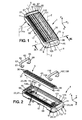
- FIG. 1 is a perspective view of a shaving blade cartridge according to the invention, the cartridge comprising a housing, three blades and two clips retaining the blades in the housing,
- FIG. 2 is an exploded perspective view of the shaving blade cartridge of Figure 1 ,
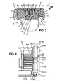
- FIG. 4 is a rear view of a shaving blade cartridge according to an embodiment of the invention, the shaving blade cartridge comprising five blades;
- FIG. 5 is a perspective view of the clip of Figure 4 .
- FIG. 6a and 6b are perspective views of a shaving blade cartridge according to a second embodiment of the invention.
- FIG. 7 shows a perspective view of a shaver comprising a handle and a cartridge, according to the invention.
- FIG. 8a to 8c show schematic sectional view along the axis referenced VIII represented on Figure 3 of through hole which can be provided on the housing respectively with a square section, a rectangular section and a circular section.
- the shaving blade cartridge 1 is attached to a handle 7 extending in a handle direction between a proximal portion Pp and a distal portion Dp.
- the handle 7 can pivot with regard to the shaving blade cartridge 1.
- the handle may also be fixed with regard to the shaving cartridge.
- the handle direction may be curved or include one or several straight portions.
- the shaving blade cartridge 1 can, for example, be releasably connected to the shaver handle 7 through a lock-and-release mechanism.
- the shaving blade cartridge 1 comprises a housing 9.
- the housing 9 extends along a longitudinal axis X-X. Viewed from the top, the housing 9 has a rectangular general shape. However, in some embodiments, the general shape of the housing 9 may be different, and for example the housing 9 could have an oval shape.
- the housing 9 comprises a top side 11, a bottom side 13 opposite to the top side 11 and a first and second longitudinal side 15, 17.
- the bottom side 13 is adapted to be arranged in front of the handle 7 whereas the top side 11 is arranged opposite to the handle 7.
- the top side 11 and the bottom side 13 can be parallel to each other.
- the first longitudinal side 15 extends along the longitudinal axis X-X.
- the second longitudinal side 17 and the first longitudinal side 15 are facing each other.
- the second longitudinal side 17 may be approximately parallel to the first longitudinal side 15, especially when the first and second longitudinal sides 15, 17 are flat.
- the second longitudinal side 17 also extends along the longitudinal axis X-X.
- the first and the second longitudinal side 15, 17 each extend in a lateral direction Z along a lateral axis Z-Z, between the top side 11 and the bottom side 13 of the housing 9.
- the first side 15 can be forward or rearward of the blade edges according to the embodiment.
- the housing 9 may also comprise, as best seen in Figure 2 , first and second lateral sides which extend between the first and second longitudinal sides 19, 21, along a transversal axis Y-Y, the transversal axis Y-Y being, for example, orthogonal to the longitudinal axis X-X and to the lateral axis Z-Z.
- the first and second lateral sides 19, 21 are arranged, in the lateral direction Z, between the top side 11 and the bottom side 13.
- the first and second lateral and longitudinal sides 15, 17, 19, 21 form together the external surface of the housing 9.
- the first and second lateral sides 19, 21 both join the longitudinal ends 23, 25 of the first and second longitudinal sides 15, 17. In a similar way, the first and second longitudinal sides 15, 17 both join the free ends 27, 29 of the first and second lateral sides 19, 21.
- the housing 9 can be plastic material. However, other materials may be used.
- the housing 9 can for example include, on the bottom side 13, a connection mechanism 31 adapted to connect the handle 7.
- the connection mechanism 31 can thus allow the release and/or the attachment of the shaving blade cartridge 1 to the handle 7.
- the housing 9 also comprises a blade receiving section 33, as represented in Figure 2 .
- the blade receiving section 33 or blade receiving area may have a general rectangular shape.
- the blade receiving section 33 is arranged on the top side 11 of the housing 9.
- the blade receiving section 33 defines a recess and is adapted to receive at least one cutting blade 35.
- the shaving blade cartridge 1 comprises at least one cutting blade 35 (also called blade in the rest of the description).
- the shaving blade cartridge 1 comprises three cutting blades 35.
- the shaving blade cartridge 1 can comprise more or less than three cutting blades 35, for example the shaving blade cartridge 1 comprises five cutting blades 35, as illustrated on Figure 4 .
- the description below is made with reference to figures representing the shaving blade cartridge 1 comprising three or five cutting blades 35.
- the number of cutting blades may be different.
- each blade 35 extends longitudinally along the longitudinal axis X-X.
- Each cutting blade 35 comprises a first and second end 37, 39 along the longitudinal axis X-X.
- the first end 37 of the cutting blades 35 is directed toward the first lateral side 19 of the housing 9, whereas the second end 39 of the cutting blade 35 is directed toward the second lateral side 21 of the housing 9.
- Each cutting blade 35 comprises a cutting edge 41.
- the cutting edge 41 extends along the longitudinal axis X-X.
- the cutting edge 41 of the cutting blade 35 is accessible at the top side 11 of the housing 9 to cut hair during shaving.
- the cutting blades 35 are L-shaped such as represented on Figures 2 and 3 .
- the cutting blades 35 thus have a cutting edge portion 43, a guided portion 45, and a bent portion 47 which is intermediate to the cutting edge portion 43 and the guided portion 45.
- the cutting edge portion 43 extends along a cutting edge portion axis.
- the cutting edge portion axis of all cutting blades 35 are positioned parallel to each other.
- each cutting blade 35 is freely mounted in the housing 9, as best seen on Figure 3 . More precisely, the blades 35 are movably mounted in the blade receiving section 33. Each cutting blade 35 is, for example, borne (or carried) by two elastic fingers 49, 51.
- the elastic fingers 49, 51 can be molded as a single piece with the housing 9 and can extend in the blade receiving section 33 towards each other and upwardly from both lateral sides 19, 21 of the housing 9.
- the guided portions 45 of the cutting blades 35 are slidingly guided in slots 53 provided in the housing 9.
- the cutting blade 35 can be supported blade having its cutting edge 41 fixed on a blade support 57 which comprises the guided portion 45 and the bent portion 47. In this case the blade support 57 is carried by the elastic fingers 49, 51.
- the blades could be bent blades, as described for instance in patent application WO2013/050606 .
- Each cutting blade 35 is retained in the housing by a clip 55.
- the clip 55 as represented in Figure 5 , comprises a first leg 59, a second leg 61 and a clip body 63.
- the clip body 63 comprises a first and a second end 65, 67.
- the first leg 59 of the clip 55 extends the first end 65 of the clip body 63 whereas the second leg 61 of the clip 55 extends the second end 67 of the clip body 63.
- the clip body 63, first leg 59 and second leg 61 form a one-piece part.
- FIG. 5 shows the clip 55 before being mounted in the housing 9.
- the clip 55 comprises a first and second end 69, 71.
- the first end 69 of the clip 55 is provided on the first leg 59.
- the second end 71 of the clip 55 is provided on the second leg 61.
- each leg 59, 61 extends to an end 69, 71.
- the clip 55 is preferably U-shaped. It is made of a formable material, for example a thin sheet of suitable metal. However, other materials may be considered.
- the width "1" of the clip is preferably sensibly constant along its length.
- the thickness "ep" of the clip 55 is preferably constant along its length.
- the width "1" and the thickness "ep" of the clip could be variable.
- the first leg 59 of the clip 55 surrounds the first longitudinal side 15 of the housing 9 and at least a portion of the bottom side 13 of the housing 9. In other words, a portion of the clip 55 is wrapped around a portion of the housing 9.
- the first leg 59 of the clip 55 comprises retaining means 73 adapted to cooperate with complementary means 75 provided on the housing 9 in order to avoid any movement of the first leg 59 with regard to the housing 9.
- the first leg 59 of the clip 55 comprises a hook 77.
- the hook 77 can be provided at the first end 69 of the first leg 59.
- the hook 77 comprises two anchoring portions 79, 81 extending on both sides of the first leg 59 of the clip 55.
- Each anchoring portion 79, 81 cooperates with a complementary portion arranged on the bottom side 13 of the housing 9.
- the bottom side 13 of the housing 9 comprises for example a recess 83, which forms the complementary means 75.
- the hook 77 cooperates with the recess 83.
- the recess 83 comprises two parts 83a, 83b, each part receiving one of the anchoring portions 79, 81.
- the first longitudinal side 15 can be provided with a cut-out 85 or notch, as best seen in Figure 6 .
- the first leg 59 of the clip 55 surrounds the cut-out 85.
- the cut-out 85 is a recess which is provided at a lateral edge of the housing.
- the cut-out defines a shoulder 123 in the housing. More precisely, as shown , the cut-out 85 passes around the housing 9 and is arranged at a common edge of the first longitudinal side 15 and the first and/or second lateral side 19, 21.
- the first leg 59 of the clip 55 which is bent around the cut-out, extends in an embodiment on the bottom side of the housing 13 and can be provided with the hook 77.
- the first longitudinal side 15 can be provided with a groove 87, as represented on figure 2 .
- the groove 87 is a narrow furrow or channel which extends in the housing without passing through the housing. More precisely, the groove 87 is arranged in a wall of the cut-out 85.
- the first leg 59 of the clip 55 surrounds the first longitudinal side 15 by extending in the groove 87. In other words, the first leg 59 of the clip 55 is received in the groove 87.
- the bottom side 13 of the housing 9 can also be provided with a groove 89, which extends the groove 87 of the first longitudinal side 15.
- the first leg 59 of the clip 55 extends in the groove 89 of the bottom side.
- the thickness "epg" of the groove 87, 89 can be the same as than the thickness "ep” of the clip 55.
- the first leg 59 of the clip 55 does not protrude outside of the housing 9 from the groove 87, 89.
- the bottom side 13 of the housing 9 can comprise a protruding portion, more precisely a fulcrum portion 91.
- the fulcrum portion 91 extends outward beyond adjacent surface portions on one side of the fulcrum portion 91.
- the first leg 59 of the clip 55 has a portion which is bent over the fulcrum portion 91, as represented in Figure 3 .
- the clip body 63 is arranged facing the top side 11 of the shaving blade cartridge 1. More precisely, the clip body 63 is facing the cutting edge 41 of the at least one cutting blade 35. In order to avoid any interference with the shaving, the clip body 63 is arranged towards one of the longitudinal ends 37, 39 of the cutting blade 35. The clip body 63 extends along the transversal axis Y-Y in its mounted position.
- the section of the through hole can be constant over the entire length of the through hole in the lateral direction Z-Z.
- the section of the through hole 93 may vary over its length along the lateral axis Z-Z.
- the dimension along the transversal axis Y-Y of the through hole can decrease from the top side 11 of the housing to the bottom side 13 of the housing 9.
- the walls defining the through hole 93 may be straight, in order to facilitate the mounting of the second leg 61 of the clip 55 in the hole.
- the walls may be orthogonal to the shaving plane, which is the plane defined as being the plane passing through the surfaces of the housing directly located forward of the cutting blade edge and rearward of the cutting blade edge.
- the walls are angled with regard to the shaving plane. For example, the angle between the walls and the shaving plane may be between 70° and 100°.
- the second leg 61 of the clip 55 which is received in the through hole 93, is bent around at least a portion of the bottom side 13, as shown on Figures 3 and 4 .
- the second leg 61 of the clip 55 can extend in a groove 95 provided on the bottom side 13 of the housing 9.
- the groove 95 for the second leg 61 is in the continuity of the groove(s) 87, 89 for the first leg 59.
- the bottom side 13 of the housing 9 can comprise a second fulcrum portion 97 (or protruding portion).
- the second fulcrum portion 97 extends outward beyond adjacent surface portions on one side of the second fulcrum portion 97.
- the second leg 61 of the clip 55 has a portion which is bent over the second fulcrum portion 97, as shown in Figure 3 .
- the housing 9 preferably can comprise a guard bar 99 and a rear cap 101.
- the guard bar 99 is forward of the cutting edge 41.
- the guard bar 99 is located in front of the cutting edges 41.
- the rear cap 101 is located rearward of the cutting edge 41. In other words, the rear cap 101 is behind the cutting edge 41.
- the rear cap 101 is preferably provided with a lubricating strip.
- the rear cap 101 preferably comprises, as shown in Figure 1 , a shaving aid member 103.
- the shaving aid member 103 extends along the longitudinal axis X-X.
- the shaving aid member 103 preferably has the same length in the longitudinal direction X than the rear cap 101, or is smaller in length than the rear cap 101.
- the shaving blade cartridge 1 comprises a second clip 105.
- the second clip 105 is identical to the first clip 55. In others embodiments, the second clip 105 may be different from the first clip.
- the first clip 55 is arranged near the first longitudinal end 23 of the at least one cutting blade 35 whereas the second clip is arranged near the second longitudinal end 25 of the at least one cutting blade 35.
- the distance between the two clips 55, 105 is smaller than the length "L" of the cutting blade 35.
- the first and the second clip 55, 105 each have a portion which is in front of the cutting blade 35. The portions of the clips 55, 105 in front of the cutting blade retain the cutting blade 35.
- the portion of clips 55, 105 in front of the cutting blade 35 touches the cutting blade 35 when the blades are in a rest-position (i.e. when no external force is applied to the shaving blade cartridge).
- the clip can comprise an aluminum alloy material.
- the blade can comprise steel alloy material. The different materials between the blade and clip enhances cathodic protection and blade longevity.
- the first leg 107 of the second clip 105 surrounds the first longitudinal side 15.
- the first leg 107 of the second clip 105 can surround a second cut-out 111 arranged on the first longitudinal side 15.
- the housing 9, as represented in Figures 1, 2 , 3 and 6 comprises a second through hole 113.
- the second through hole 113 is similar to the previous disclosed through hole 93 (also called the first through hole 93).
- the second through hole is intended to receive the second leg 109 of the second clip 105.
- the first through hole 93 is located toward the first lateral side 19
- the second through hole is located toward the second lateral side 21.
- the second through hole 113 extends transversally to the longitudinal axis X-X along the lateral axis Z-Z through the housing 9 between the top side 11 and the bottom side 13.
- the second through hole 113 is, as represented on Figures 1, 2 , 3, 4 and 6 , separated from the blade receiving section 33 and is separated from the first through hole 93.
- the distance between the first and the second through hole 93, 113 in the longitudinal direction X is lower than the length L of the cutting blade 35 in the longitudinal direction X.
- the first through hole 93 can be arranged near the first lateral side 19 whereas the second through hole 113 can be arranged near the second lateral side 21.
- the second leg 109 of the second clip 105 is received in the second through hole 113.
- the second through hole 113 is arranged near the second longitudinal side 17.
- the first cut-out 85 is arranged at the common edge 115 of the first longitudinal side 15 and the first lateral side 19 whereas the second cut-out 111 is arranged at the common edge of the first longitudinal side 17 and the second lateral side 21.
- the second leg 109 of the second clip 105 As for the first clip 55, the second leg 109 of the second clip 105, which is received in the second through hole 113, is bent around at least a portion of the bottom side 13, as shown on Figures 3 and 4 .
- the second leg 109 of the second clip 105 can extend in a groove 117 provided on the bottom side 13 of the housing 9.
- the groove 117 for the second leg 109 of the second clip 105 is in the continuity of a groove 119 arranged in the housing 9 for the first leg 107 of the second clip 105.
- the groove 119 extends on the first longitudinal side 15.
- the bottom side 13 of the housing 9 can comprise a fulcrum portion 121 (or protruding portion) arranged to receive a portion of the second leg 109 of the second clip 105 which is bent over said fulcrum portion 121.
- the second end of the second clip 105, corresponding to the free end of the second leg can be tapered (sensibly V-shaped).
- the shaving blade cartridge 1 comprises a mid-plane Pm orthogonal to the longitudinal axis X-X, as represented on Figure 1 .
- the mid-plane Pm extends at equal distance between the first and second lateral sides 19, 21.
- the mid-plane Pm can form a symmetrical plan of the shaving blade cartridge 1.
- the first through hole 93 is arranged forward of the cutting blades 35; more precisely the first through hole 93 is arranged in or adjacent to the guard bar 99 when it exists.
- the guard bar 99 is sensibly at or near the second longitudinal side 17.
- the rear cap 101 is thus preferably at or near the first longitudinal side 15.
- the first leg 59 of the first clip 55 surrounds the rear cap 101.
- the second through hole 113 is also arranged in or adjacent to the guard bar 99.
- the first leg 107 of the second clip 105 surrounds the rear cap 101.
- the first and second cut-outs 85, 111 are then disposed at each free ends of the rear cap 101 and/or of the shaving aid member 103.
- both cut-outs 85, 111 extend then the rear cap 101 and/or the shaving aid member 103.
- the shaving aid member 103 is then smaller in length than the cutting blade 35.
- the rear cap 101 and/or the shaving aid member 103 extends thus between the two clips 55, 105.
- the first through hole 93 is arranged rearward of the cutting blades 35; more precisely, the first through hole 93 is arranged in or adjacent to the rear cap 101 when it exists.
- the rear cap 101 is then preferably at or near the second longitudinal side 17.
- the first leg 59 of the first clip 55 surrounds the guard bar 99.
- the second through hole 113 is also arranged in or adjacent to the rear cap 101.
- the first leg 107 of the second clip 105 surrounds the rear cap 101.
- the first and second cut-outs 85, 111 are then disposed at each free ends of the guard bar 99. In other words, the guard bar 99 extends then between both cut-outs 85, 111.
- the guard bar 99 is then smaller in length than the at least one cutting blade 35.
- the guard bar 99 extends between the two clips 55, 105.
- the guard bar 99 is smaller in length than the cutting blades 35.
- the first through hole 93 can be arranged in or adjacent to the guard bar 99, whereas the second through hole 113 is arranged in or adjacent to the rear cap 101.
- the second leg 61 of the first clip 55 is received in the first through hole 93 arranged in or adjacent to the guard bar 99, whereas the first leg 59 of the first clip 55 surrounds the first longitudinal side 15 provided at the rear cap 101 side.
- the second leg 109 of the second clip 105 is received in the second through hole 113 arranged in or adjacent to the rear cap 101, whereas the first leg 107 of the second clip 105 surrounds the first longitudinal side 15 provided at the guard bar 101 side.
- the clips 55, 105 can be assembled to the housing 9 by a system for the manufacture of clip-housing assemblies with, for example, the followings steps:
- the bottom of the housing 9 can also comprise in an embodiment a protrusion 125.
- the protrusion 125 extends along the longitudinal axis X-X and is provided sensibly in the middle of the bottom side 13 of the housing 9.
- the protrusion protrudes from the bottom of the housing 9 along the lateral axis Z-Z.
- the first end 37 of the clip 55 is on one side of the protrusion 125, whereas the second end 71 of the clip is on the other side of the protrusion 125.
- the protrusion 125 can advantageously protect the clip 55 from the assembly clamps.
- the protrusion 125 does not allow the assembly clamps to accidently grab the clip end on their remove movement, and thus the protrusion 125 secures the position of the clip during mounting steps.
- the lower horizontal plane of the protrusion is in a substantially similar horizontal plane of the lower section of each leg of the clip disposed on the underside of the housing.
Landscapes
- Life Sciences & Earth Sciences (AREA)
- Forests & Forestry (AREA)
- Engineering & Computer Science (AREA)
- Mechanical Engineering (AREA)
- Dry Shavers And Clippers (AREA)
- Knives (AREA)
Abstract
Description
- The embodiments of the present invention relate to shaving blade cartridges and shavers having such shaving blade cartridges.
- In particular, the present invention is related to a shaving blade cartridge comprising:
- a housing extending along a longitudinal axis, having a top side, a bottom side opposite to the top side and a first and second longitudinal sides, each extending longitudinally along the longitudinal axis between the top and bottom sides, the housing being provided with a through hole extending transversally to the longitudinal axis through the housing between the top side and the bottom side, at least one cutting blade mounted in the housing between the first and second longitudinal sides, and having a cutting edge extending along the longitudinal axis, a clip retaining the at least one cutting blade in the housing and having a first leg, a second leg and a clip body extending between the first and second legs.
- A through hole is neither a groove nor a slot. The through hole of the housing is an aperture which passes through the housing from the top side of the housing to the bottom side of the housing and which is completely surrounded by material when viewed from the top side or from a cross-section.
-
U.S. Patent No. 8,286,354 discloses a razor having two clips, each clip comprising a pair of legs that extend through a pair of through holes provided in the housing. The two pairs of through holes in the housing require important structural modifications of the housing of known cartridges. Moreover, the assembly of the clip can be difficult. Indeed, during the manufacturing process, both legs of the clip have to be in correspondence with two different through holes, which requires strict tolerances to be applied to the clip and to the through holes. -
U.S. Patent No. 4,270,268 describes a cartridge having a clip retaining at least a blade. The clip disclosed inU.S. Patent No. 4,270,268 surrounds the housing and is received at least in grooves provided in the housing. The installation of such clip is easy, since it surrounds the housing. However, such clip is easily movable and can unintentionally be removed by a user during shaving. Indeed, when the clips are removed, the blades are not retained in the housing resulting in their free movement. - Various solutions have been used in order to avoid such drawbacks.
-
WO9610473 -
WO9717174 - To avoid a complicated assembly,
WO9955499 - However, the annular clip lowers the shaving surface, which is the active surface during the shaving.
- The embodiments of the present invention have objectives to mitigate the drawbacks discussed above.
- To this aim, according to an embodiment of the invention, such a shaving blade cartridge is characterized in that a first leg of the clip surrounds a first longitudinal side and at least a portion of the bottom side of the housing, and the second leg of the clip is received in a through hole.
- With these features, the blades are retained in the housing in a secure way, without lowering the shaving surface (also called shaving window). The leg of the clips received in the through hole enables the clip to be securely maintained in the housing. The leg of the clip surrounding the housing enables an easy assembly of the clip. The clip provided to retain the blades does not require an important structural modification of the existing housing and is easily assembled to the housing without causing stress to the clips which could cause the clip to not withstand the forces encountered during shaving. The embodiments of the present invention disclosed in this application are distinguishable from
U.S. Patent No. 8,286,354 , which requires two pairs of apertures extending through the housing from the top surface to the bottom surface, with each pair of apertures having one aperture in front of the cutting edge and one aperture behind the cutting edge, and a pair of spaced apart clips each having a pair of legs extending through the corresponding pair of apertures. The present invention requires only one through hole on each side of the blade assembly for one leg of the clip to go through; the second leg of the clip goes around the cartridge body. - In some embodiments, a person of ordinary skill in the art might also use one or more of the following features:
- the clip body extends along a transversal axis, the transversal axis being orthogonal to the longitudinal axis, and the clip body is arranged facing the top side of the blade cartridge; the position of the clip enables a large shaving surface, to produce an esthetical cartridge, and the clip is easy to assemble;
- the second leg of the clip is bent about at least a portion of the bottom side; the bent portion provides a second maintaining area of the clip, which leads to a robust assembly and minimizes the risk of unintentional disassembly of the clip;
- the first leg of the clip comprises a hook, the bottom side of the housing comprises a recess, and the hook cooperates with the recess; the hook and the recess cooperate together to provide the retaining of the first leg of the clip to the housing;
- the bottom side comprises a fulcrum portion extending outward beyond adjacent surface portions on one side of the fulcrum portion, and wherein one of the first and second legs of the clip has a portion which is bent over the fulcrum portion; the fulcrum portion enables the leg of the clip to be bent easily and to retain the clip;
- the bottom side comprises a first and second fulcrum portion, each fulcrum portion extending outward beyond adjacent surface portions on one side of said fulcrum portion, the first leg of the clip being bent over the first fulcrum portion, and the second leg of the clip being bent over the second fulcrum portion; the fulcrum portion enables the leg of the clip to be bent;
- the housing defines a cut-out, the first leg of the clip surrounding the cut-out; the clip does not project beyond the housing (in other words, the clip is totally integrated to the housing), which provides shaving without discomfort;
- the housing comprises a guard bar and a rear cap, the guard bar being forward of the blade edge and the rear cap being rearward of the blade edge, and wherein the through hole is arranged in or adjacent to the guard bar; the guard bar can, for example, be manufactured directly with the through hole;
- the first leg of the clip surrounds the first longitudinal side of the housing rearward of the blade edge;
- the housing comprises a guard bar and a rear cap, the guard bar being forward of the blade edge and the rear cap being rearward of the blade edge, and wherein the through hole is arranged in or adjacent to the rear cap;
- the shaving blade cartridge is provided with a second clip retaining the at least one cutting blade in the housing, the second clip having a first leg, a second leg and a clip body extending between the first and second legs, and the second leg of the second clip is received in a second through hole provided in the housing and extending through the housing between the top side and the bottom side, and the first leg of the second clip surrounds the first longitudinal side of the housing and at least a portion of the bottom side of the housing; both clips retain the blades in the housing;
- the rear cap comprises a shaving aid member, the shaving aid member extending along the longitudinal axis and being smaller in length than the cutting blade, and wherein the shaving aid member extends between the two clips; the clips do not limit the active surface of the shaving aid;
- the guard bar extends along the longitudinal axis, the guard bar being smaller in length than the cutting blade, and wherein the guard bar preferably extends between the two clips; the clips do not limit the active surface of the guard bar.
- the bottom side of the housing comprises a protrusion, which extends between a first and a second end of the clip; this protrusion prevents the assembly machine from disassembling the clip by mistake while retreating. The protrusion makes the disassembly more difficult.
- The embodiments of the present invention are also directed to a shaver comprising a handle and a shaving blade cartridge as described above, the shaving blade cartridge being connected to the handle.
- Other characteristics and advantages of the embodiments of the present invention will readily appear from the following description of one of its embodiments, provided as non-limitative examples, and shown in the accompanying drawings.
- -
Figure 1 is a perspective view of a shaving blade cartridge according to the invention, the cartridge comprising a housing, three blades and two clips retaining the blades in the housing, - -
Figure 2 is an exploded perspective view of the shaving blade cartridge ofFigure 1 , - -
Figure 3 is a lateral view of the shaving blade cartridge ofFigure 1 , - -
Figure 4 is a rear view of a shaving blade cartridge according to an embodiment of the invention, the shaving blade cartridge comprising five blades; - -
Figure 5 is a perspective view of the clip ofFigure 4 , - -
Figure 6a and 6b are perspective views of a shaving blade cartridge according to a second embodiment of the invention, - -
Figure 7 shows a perspective view of a shaver comprising a handle and a cartridge, according to the invention. - -
Figures 8a to 8c show schematic sectional view along the axis referenced VIII represented onFigure 3 of through hole which can be provided on the housing respectively with a square section, a rectangular section and a circular section. - On the different figures, the same reference signs designate like or similar elements.
-
Figure 1 shows ashaving blade cartridge 1 of a wet razor, a shaver 3 theblades 5 of which are not driven by a motor relative to the shaving blade cartridge. - As seen on
Figure 7 , theshaving blade cartridge 1 is attached to a handle 7 extending in a handle direction between a proximal portion Pp and a distal portion Dp. The handle 7 can pivot with regard to theshaving blade cartridge 1. In other embodiments, the handle may also be fixed with regard to the shaving cartridge. The handle direction may be curved or include one or several straight portions. Theshaving blade cartridge 1 can, for example, be releasably connected to the shaver handle 7 through a lock-and-release mechanism. - As depicted on
Figures 1, 2 and3 , theshaving blade cartridge 1 comprises ahousing 9. Thehousing 9 extends along a longitudinal axis X-X. Viewed from the top, thehousing 9 has a rectangular general shape. However, in some embodiments, the general shape of thehousing 9 may be different, and for example thehousing 9 could have an oval shape. Thehousing 9 comprises atop side 11, abottom side 13 opposite to thetop side 11 and a first and secondlongitudinal side bottom side 13 is adapted to be arranged in front of the handle 7 whereas thetop side 11 is arranged opposite to the handle 7. Thetop side 11 and thebottom side 13 can be parallel to each other. The firstlongitudinal side 15 extends along the longitudinal axis X-X. The secondlongitudinal side 17 and the firstlongitudinal side 15 are facing each other. The secondlongitudinal side 17 may be approximately parallel to the firstlongitudinal side 15, especially when the first and secondlongitudinal sides longitudinal side 17 also extends along the longitudinal axis X-X. The first and the secondlongitudinal side top side 11 and thebottom side 13 of thehousing 9. Thefirst side 15 can be forward or rearward of the blade edges according to the embodiment. - The
housing 9 may also comprise, as best seen inFigure 2 , first and second lateral sides which extend between the first and secondlongitudinal sides top side 11 and thebottom side 13. The first and second lateral andlongitudinal sides housing 9. The first and second lateral sides 19, 21 both join the longitudinal ends 23, 25 of the first and secondlongitudinal sides longitudinal sides - The
housing 9 can be plastic material. However, other materials may be used. Thehousing 9 can for example include, on thebottom side 13, aconnection mechanism 31 adapted to connect the handle 7. Theconnection mechanism 31 can thus allow the release and/or the attachment of theshaving blade cartridge 1 to the handle 7. - The
housing 9 also comprises ablade receiving section 33, as represented inFigure 2 . Theblade receiving section 33 or blade receiving area may have a general rectangular shape. Theblade receiving section 33 is arranged on thetop side 11 of thehousing 9. Theblade receiving section 33 defines a recess and is adapted to receive at least onecutting blade 35. In other words, theshaving blade cartridge 1 comprises at least one cutting blade 35 (also called blade in the rest of the description). As depicted onFigures 1, 2 ,3 and6 , theshaving blade cartridge 1 comprises three cuttingblades 35. However, in other embodiments, theshaving blade cartridge 1 can comprise more or less than three cuttingblades 35, for example theshaving blade cartridge 1 comprises fivecutting blades 35, as illustrated onFigure 4 . The description below is made with reference to figures representing theshaving blade cartridge 1 comprising three or fivecutting blades 35. However, as previously mentioned, the number of cutting blades may be different. - The
blades 35 are mounted in thehousing 9 in theblade receiving section 33 between the first and secondlongitudinal sides housing 9. As shown infigures 1, 2 ,3 and6 eachblade 35 extends longitudinally along the longitudinal axis X-X. Eachcutting blade 35 comprises a first andsecond end first end 37 of thecutting blades 35 is directed toward the firstlateral side 19 of thehousing 9, whereas thesecond end 39 of thecutting blade 35 is directed toward the secondlateral side 21 of thehousing 9. Eachcutting blade 35 comprises acutting edge 41. Thecutting edge 41 extends along the longitudinal axis X-X. Thecutting edge 41 of thecutting blade 35 is accessible at thetop side 11 of thehousing 9 to cut hair during shaving. - For example, the
cutting blades 35 are L-shaped such as represented onFigures 2 and3 . Thecutting blades 35 thus have acutting edge portion 43, a guidedportion 45, and abent portion 47 which is intermediate to thecutting edge portion 43 and the guidedportion 45. Thecutting edge portion 43 extends along a cutting edge portion axis. Advantageously, the cutting edge portion axis of all cuttingblades 35 are positioned parallel to each other. - In an embodiment, each cutting
blade 35 is freely mounted in thehousing 9, as best seen onFigure 3 . More precisely, theblades 35 are movably mounted in theblade receiving section 33. Eachcutting blade 35 is, for example, borne (or carried) by twoelastic fingers elastic fingers housing 9 and can extend in theblade receiving section 33 towards each other and upwardly from bothlateral sides housing 9. As shown onFigure 3 , the guidedportions 45 of thecutting blades 35 are slidingly guided inslots 53 provided in thehousing 9. For example, thecutting blade 35 can be supported blade having itscutting edge 41 fixed on ablade support 57 which comprises the guidedportion 45 and thebent portion 47. In this case theblade support 57 is carried by theelastic fingers - However, in some others embodiments (not shown on the figures) the blades could be bent blades, as described for instance in patent application
WO2013/050606 . - Each
cutting blade 35 is retained in the housing by aclip 55. - The
clip 55, as represented inFigure 5 , comprises afirst leg 59, asecond leg 61 and aclip body 63. Theclip body 63 comprises a first and asecond end first leg 59 of theclip 55 extends thefirst end 65 of theclip body 63 whereas thesecond leg 61 of theclip 55 extends thesecond end 67 of theclip body 63. Theclip body 63,first leg 59 andsecond leg 61 form a one-piece part. -
Figure 5 shows theclip 55 before being mounted in thehousing 9. Theclip 55 comprises a first andsecond end first end 69 of theclip 55 is provided on thefirst leg 59. Thesecond end 71 of theclip 55 is provided on thesecond leg 61. In other words, eachleg end clip 55 is preferably U-shaped. It is made of a formable material, for example a thin sheet of suitable metal. However, other materials may be considered. The width "1" of the clip is preferably sensibly constant along its length. Moreover, as represented onFigure 5 , the thickness "ep" of theclip 55 is preferably constant along its length. - In others embodiments, the width "1" and the thickness "ep" of the clip could be variable.
- As shown on the
Figures 1 to 4 and6 to 7 , when being mounted, thefirst leg 59 of theclip 55 surrounds the firstlongitudinal side 15 of thehousing 9 and at least a portion of thebottom side 13 of thehousing 9. In other words, a portion of theclip 55 is wrapped around a portion of thehousing 9. - In another embodiment, as shown on
Figure 4 , thefirst leg 59 of theclip 55 comprises retaining means 73 adapted to cooperate with complementary means 75 provided on thehousing 9 in order to avoid any movement of thefirst leg 59 with regard to thehousing 9. As best seen onFigure 4 , for example, thefirst leg 59 of theclip 55 comprises a hook 77. The hook 77 can be provided at thefirst end 69 of thefirst leg 59. As represented, the hook 77 comprises two anchoringportions first leg 59 of theclip 55. Each anchoringportion bottom side 13 of thehousing 9. Thebottom side 13 of thehousing 9 comprises for example a recess 83, which forms the complementary means 75. Thus, the hook 77 cooperates with the recess 83. More precisely, the recess 83 comprises twoparts 83a, 83b, each part receiving one of the anchoringportions - The first
longitudinal side 15 can be provided with a cut-out 85 or notch, as best seen inFigure 6 . Thefirst leg 59 of theclip 55 surrounds the cut-out 85. The cut-out 85 is a recess which is provided at a lateral edge of the housing. The cut-out defines ashoulder 123 in the housing. More precisely, as shown , the cut-out 85 passes around thehousing 9 and is arranged at a common edge of the firstlongitudinal side 15 and the first and/or secondlateral side first leg 59 of theclip 55, which is bent around the cut-out, extends in an embodiment on the bottom side of thehousing 13 and can be provided with the hook 77. - Alternatively or additionally to the cut-
out 85, the firstlongitudinal side 15 can be provided with agroove 87, as represented onfigure 2 . Thegroove 87 is a narrow furrow or channel which extends in the housing without passing through the housing. More precisely, thegroove 87 is arranged in a wall of the cut-out 85. Thefirst leg 59 of theclip 55 surrounds the firstlongitudinal side 15 by extending in thegroove 87. In other words, thefirst leg 59 of theclip 55 is received in thegroove 87. - The
bottom side 13 of thehousing 9 can also be provided with agroove 89, which extends thegroove 87 of the firstlongitudinal side 15. Thefirst leg 59 of theclip 55 extends in thegroove 89 of the bottom side. The thickness "epg" of thegroove clip 55. Thus, thefirst leg 59 of theclip 55 does not protrude outside of thehousing 9 from thegroove - As shown on
Figure 3 , thebottom side 13 of thehousing 9 can comprise a protruding portion, more precisely a fulcrum portion 91. The fulcrum portion 91 extends outward beyond adjacent surface portions on one side of the fulcrum portion 91. Thefirst leg 59 of theclip 55 has a portion which is bent over the fulcrum portion 91, as represented inFigure 3 . - The
clip body 63 is arranged facing thetop side 11 of theshaving blade cartridge 1. More precisely, theclip body 63 is facing thecutting edge 41 of the at least onecutting blade 35. In order to avoid any interference with the shaving, theclip body 63 is arranged towards one of the longitudinal ends 37, 39 of thecutting blade 35. Theclip body 63 extends along the transversal axis Y-Y in its mounted position. - The
second leg 61 of theclip 55 is received in a throughhole 93 provided in thehousing 9. The throughhole 93 extends transversally to the longitudinal axis X-X along the lateral axis Z-Z through thehousing 9 between thetop side 11 and thebottom side 13. The throughhole 93 is neither a slot nor a groove. The throughhole 93 extends through thehousing 9 and when viewed in transversal cross-sectional view is laterally surrounded by the housing's material. As represented onFigures 8a and 8c , the through hole may have a circular shape section or a square one. The throughhole 93 can also have a rectangular shape section, as represented onFigure 1 and onFigure 8b . The section of the through hole can be constant over the entire length of the through hole in the lateral direction Z-Z. However, in some embodiments, the section of the throughhole 93 may vary over its length along the lateral axis Z-Z. As represented onFigure 3 , the dimension along the transversal axis Y-Y of the through hole can decrease from thetop side 11 of the housing to thebottom side 13 of thehousing 9. The walls defining the throughhole 93 may be straight, in order to facilitate the mounting of thesecond leg 61 of theclip 55 in the hole. In addition the walls may be orthogonal to the shaving plane, which is the plane defined as being the plane passing through the surfaces of the housing directly located forward of the cutting blade edge and rearward of the cutting blade edge. In another embodiment, the walls are angled with regard to the shaving plane. For example, the angle between the walls and the shaving plane may be between 70° and 100°. - The shape of the
clip 55, and more particularly of thesecond leg 61 is complementary to the shape of the throughhole 93 and can be different from the shape described above with reference toFigure 5 . Viewed in a transversal section, the shape of the clip can be rectangular, square, or oval. The longitudinal axis X-X and the lateral axis Z-Z are preferably orthogonal. The throughhole 93 is, as represented onFigures 1, 2 ,3, 4 and6 , separated from theblade receiving section 33. For example, the throughhole 93 is arranged near the firstlateral side 19 and/or near the secondlongitudinal side 17. More precisely, the throughhole 93 is arranged between the secondlongitudinal side 17 and theblade receiving section 33. - The
second leg 61 of theclip 55, which is received in the throughhole 93, is bent around at least a portion of thebottom side 13, as shown onFigures 3 and 4 . Thesecond leg 61 of theclip 55 can extend in agroove 95 provided on thebottom side 13 of thehousing 9. For example, thegroove 95 for thesecond leg 61 is in the continuity of the groove(s) 87, 89 for thefirst leg 59. - The
bottom side 13 of thehousing 9 can comprise a second fulcrum portion 97 (or protruding portion). Thesecond fulcrum portion 97 extends outward beyond adjacent surface portions on one side of thesecond fulcrum portion 97. Thesecond leg 61 of theclip 55 has a portion which is bent over thesecond fulcrum portion 97, as shown inFigure 3 . - The
second end 71 of theclip 55, corresponding to the free end of thesecond leg 61, is preferably tapered (sensibly V-shaped). - The
housing 9 preferably can comprise aguard bar 99 and arear cap 101. Theguard bar 99 is forward of thecutting edge 41. Theguard bar 99 is located in front of the cutting edges 41. Therear cap 101 is located rearward of thecutting edge 41. In other words, therear cap 101 is behind thecutting edge 41. - The
rear cap 101 is preferably provided with a lubricating strip. In other words, therear cap 101 preferably comprises, as shown inFigure 1 , a shavingaid member 103. The shavingaid member 103 extends along the longitudinal axis X-X. The shavingaid member 103 preferably has the same length in the longitudinal direction X than therear cap 101, or is smaller in length than therear cap 101. - As shown in
Figures 1, 2 ,3 and6 , theshaving blade cartridge 1 comprises asecond clip 105. Thesecond clip 105 is identical to thefirst clip 55. In others embodiments, thesecond clip 105 may be different from the first clip. Thefirst clip 55 is arranged near the firstlongitudinal end 23 of the at least onecutting blade 35 whereas the second clip is arranged near the secondlongitudinal end 25 of the at least onecutting blade 35. The distance between the twoclips cutting blade 35. The first and thesecond clip cutting blade 35. The portions of theclips cutting blade 35. The portion ofclips cutting blade 35 touches thecutting blade 35 when the blades are in a rest-position (i.e. when no external force is applied to the shaving blade cartridge). In addition, the clip can comprise an aluminum alloy material. The blade can comprise steel alloy material. The different materials between the blade and clip enhances cathodic protection and blade longevity. - The shape of the
second clip 105 is similar to the shape of the first clip 55: thesecond clip 105 comprises afirst leg 107, asecond leg 109 and aclip body 110 extending between thefirst leg 107 and thesecond leg 109. - The
first leg 107 of thesecond clip 105 surrounds the firstlongitudinal side 15. Thefirst leg 107 of thesecond clip 105 can surround a second cut-out 111 arranged on the firstlongitudinal side 15. - In the embodiment with two
clips housing 9, as represented inFigures 1, 2 ,3 and6 comprises a second throughhole 113. The second throughhole 113 is similar to the previous disclosed through hole 93 (also called the first through hole 93). The second through hole is intended to receive thesecond leg 109 of thesecond clip 105. Whereas the first throughhole 93 is located toward the firstlateral side 19, the second through hole is located toward the secondlateral side 21. The second throughhole 113 extends transversally to the longitudinal axis X-X along the lateral axis Z-Z through thehousing 9 between thetop side 11 and thebottom side 13. The second throughhole 113 is, as represented onFigures 1, 2 ,3, 4 and6 , separated from theblade receiving section 33 and is separated from the first throughhole 93. The distance between the first and the second throughhole cutting blade 35 in the longitudinal direction X. The first throughhole 93 can be arranged near the firstlateral side 19 whereas the second throughhole 113 can be arranged near the secondlateral side 21. - The
second leg 109 of thesecond clip 105 is received in the second throughhole 113. As previously said, the second throughhole 113 is arranged near the secondlongitudinal side 17. The first cut-out 85 is arranged at thecommon edge 115 of the firstlongitudinal side 15 and the firstlateral side 19 whereas the second cut-out 111 is arranged at the common edge of the firstlongitudinal side 17 and the secondlateral side 21. - As for the
first clip 55, thesecond leg 109 of thesecond clip 105, which is received in the second throughhole 113, is bent around at least a portion of thebottom side 13, as shown onFigures 3 and 4 . Thesecond leg 109 of thesecond clip 105 can extend in agroove 117 provided on thebottom side 13 of thehousing 9. For example, thegroove 117 for thesecond leg 109 of thesecond clip 105 is in the continuity of agroove 119 arranged in thehousing 9 for thefirst leg 107 of thesecond clip 105. Thegroove 119 extends on the firstlongitudinal side 15. - The
bottom side 13 of thehousing 9 can comprise a fulcrum portion 121 (or protruding portion) arranged to receive a portion of thesecond leg 109 of thesecond clip 105 which is bent over saidfulcrum portion 121. - The second end of the
second clip 105, corresponding to the free end of the second leg can be tapered (sensibly V-shaped). - The
shaving blade cartridge 1 comprises a mid-plane Pm orthogonal to the longitudinal axis X-X, as represented onFigure 1 . The mid-plane Pm extends at equal distance between the first and second lateral sides 19, 21. The mid-plane Pm can form a symmetrical plan of theshaving blade cartridge 1. - In a first embodiment, represented on
Figures 1, 2 and3 , the first throughhole 93 is arranged forward of thecutting blades 35; more precisely the first throughhole 93 is arranged in or adjacent to theguard bar 99 when it exists. Theguard bar 99 is sensibly at or near the secondlongitudinal side 17. Therear cap 101 is thus preferably at or near the firstlongitudinal side 15. Thefirst leg 59 of thefirst clip 55 surrounds therear cap 101. - The second through
hole 113 is also arranged in or adjacent to theguard bar 99. Thefirst leg 107 of thesecond clip 105 surrounds therear cap 101. - As shown in
Figures 1, 2 and3 , the first and second cut-outs rear cap 101 and/or of the shavingaid member 103. In other words, between both cut-outs rear cap 101 and/or the shavingaid member 103. The shavingaid member 103 is then smaller in length than thecutting blade 35. Therear cap 101 and/or the shavingaid member 103 extends thus between the twoclips - In a second embodiment, represented on
Figure 6A and Figure 6B , the first throughhole 93 is arranged rearward of thecutting blades 35; more precisely, the first throughhole 93 is arranged in or adjacent to therear cap 101 when it exists. Therear cap 101 is then preferably at or near the secondlongitudinal side 17. Thefirst leg 59 of thefirst clip 55 surrounds theguard bar 99. The second throughhole 113 is also arranged in or adjacent to therear cap 101. Thefirst leg 107 of thesecond clip 105 surrounds therear cap 101. As shown inFigure 6 , the first and second cut-outs guard bar 99. In other words, theguard bar 99 extends then between both cut-outs guard bar 99 is then smaller in length than the at least onecutting blade 35. Theguard bar 99 extends between the twoclips guard bar 99 is smaller in length than thecutting blades 35. - In others embodiments (not shown), the first through
hole 93 can be arranged in or adjacent to theguard bar 99, whereas the second throughhole 113 is arranged in or adjacent to therear cap 101. Thus, thesecond leg 61 of thefirst clip 55 is received in the first throughhole 93 arranged in or adjacent to theguard bar 99, whereas thefirst leg 59 of thefirst clip 55 surrounds the firstlongitudinal side 15 provided at therear cap 101 side. Thesecond leg 109 of thesecond clip 105 is received in the second throughhole 113 arranged in or adjacent to therear cap 101, whereas thefirst leg 107 of thesecond clip 105 surrounds the firstlongitudinal side 15 provided at theguard bar 101 side. - The
clips housing 9 by a system for the manufacture of clip-housing assemblies with, for example, the followings steps: - providing the
clip - assembling the
clip first leg longitudinal side 15 of thehousing 9 and thesecond leg longitudinal side 17 of thehousing 9, - deforming the first and
second legs bottom side 13 of thehousing 9 to hold thecutting blades 35 within the housing 9 (and more precisely within the blade receiving section 33). - The first and
second legs - The bottom of the
housing 9 can also comprise in an embodiment aprotrusion 125. Theprotrusion 125 extends along the longitudinal axis X-X and is provided sensibly in the middle of thebottom side 13 of thehousing 9. The protrusion protrudes from the bottom of thehousing 9 along the lateral axis Z-Z. In a mounted position of theclip 55 thefirst end 37 of theclip 55 is on one side of theprotrusion 125, whereas thesecond end 71 of the clip is on the other side of theprotrusion 125. Theprotrusion 125 can advantageously protect theclip 55 from the assembly clamps. Indeed, after the legs of the clips are bent into their mounted position by the assembly clamps, it may happen that the assembly clamps accidentally grab the ends of the clip when being moved away or removed from the blade cartridge provided with the clip, which can unbend the clip and result in scrapping the entire head. Theprotrusion 125 does not allow the assembly clamps to accidently grab the clip end on their remove movement, and thus theprotrusion 125 secures the position of the clip during mounting steps. The lower horizontal plane of the protrusion is in a substantially similar horizontal plane of the lower section of each leg of the clip disposed on the underside of the housing.
Claims (15)
- A shaving blade cartridge (1) comprising :a housing (9) extending along a longitudinal axis (X-X), having a top side (11), a bottom side (13) opposite to the top side (11) and first and second longitudinal sides (15, 17), each extending longitudinally along the longitudinal axis (X-X) between the top and bottom sides, the housing (9) being provided with a through hole (93) extending transversally to the longitudinal axis (X-X) through the housing (9) between the top side (11) and the bottom side (13),at least one cutting blade (35) mounted in the housing (9) between the first and second longitudinal sides (15, 17), and having a cutting edge extending along the longitudinal axis (X-X),a clip (55) retaining the at least one cutting blade (35) in the housing (9) and having a first leg (59), a second leg (61) and a clip body (63) extending between the first and second legs (59, 61),characterized in thatthe first leg (59) of the clip (55) surrounds the first longitudinal side (15) and at least a portion of the bottom side (13) of the housing (9), andthe second leg (61) of the clip (55) is received in the through hole (93).
- A shaving blade cartridge (1) according to claim 1, wherein the clip body (63) extends along a transversal axis (Y-Y), the transversal axis (Y-Y) being orthogonal to the longitudinal axis (X-X), and wherein the clip body (63) is arranged facing the top side (11) of the blade cartridge (1).
- A shaving blade cartridge (1) according to any of claims 1 to 2, wherein the second leg (61) of the clip (55) is bent about at least a portion of the bottom side (13).
- A shaving blade cartridge (1) according to any of claims 1 to 3, wherein the first leg (59) of the clip (55) comprises a hook (77), the bottom side (13) of the housing (9) comprises a recess (83), and the hook (77) cooperates with the recess (83).
- A shaving blade cartridge (1) according to any of claims 1 to 4, wherein the bottom side (13) comprises a fulcrum portion (91, 97) extending outward beyond adjacent surface portions on one side of said fulcrum portion (91, 97), and wherein one of the first and second legs (59, 61) of the clip (55) has a portion which is bent over said fulcrum portion (91, 97).
- A shaving blade cartridge (1) according to any of claims 1 to 5, wherein the bottom side (13) comprises a first and second fulcrum portions (91, 97), each fulcrum portion (91, 97) extending outward beyond adjacent surface portions on one side of said fulcrum portion (91, 97), the first leg (59) of the clip (55) being bent over the first fulcrum portion (91, 97), and the second leg (61) of the clip (59, 61) being bent over the second fulcrum portion (91, 97).
- A shaving blade cartridge (1) according to the preceding claim, wherein the housing (9) defines a cut-out (85), the first leg (59) of the clip (55) surrounding said cut-out (85).
- A shaving blade cartridge (1) according to any of claims 1 to 6, wherein the housing (9) comprises a guard bar (99) and a rear cap (101), the guard bar (99) being forward of the blade edge (41) and the rear cap (101) being rearward of the blade edge (41), and wherein the through hole (93) is arranged in or adjacent to the guard bar (99).
- A shaving blade cartridge (1) according to the preceding claim, wherein the first leg (59) of the clip (55) surrounds the first longitudinal side (15) rearward of the blade edge (41).
- A shaving blade cartridge (1) according to any of claims 1 to 7, wherein the housing (9) comprises a guard bar (99) and a rear cap (101), the guard bar (99) being forward of the blade edge (41) and the rear cap (101) being rearward of the blade edge (41), and wherein the through hole (93) is arranged in or adjacent to the rear cap (101).
- A shaving blade cartridge (1) according to one of claims 1 to 10, further provided with a second clip (105) retaining the at least one cutting blade (35) in the housing (9), the second clip (105) having a first leg (107), a second leg (109) and a clip body (110) extending between the first and second legs (107, 109), and the second leg (109) of the second clip (105) is received in a second through hole (113) provided in the housing (9) and extending through the housing between the top side (11) and the bottom side (13), and the first leg (107) of the second clip (105) surrounds the first longitudinal side (15) and at least a portion of the bottom side (13) of the housing (9).
- A shaving blade cartridge (1) according to the preceding claim, wherein the rear cap (101) comprises a shaving aid member (103), the shaving aid member (103) extending along the longitudinal axis (X-X) and being smaller in length than the cutting blade (35), and wherein the shaving aid member (103) extends between the two clips (55, 105).
- A shaving blade cartridge (1) according to claim 11 or 12, wherein the guard bar (99) extends along the longitudinal axis (X-X), the guard bar (99) being smaller in length than the cutting blade (35), and wherein the guard bar (99) extends between the two clips (55, 105).
- A shaving blade cartridge (1) according to any of claims 1 to 13, wherein the bottom side (13) of the housing (9) comprises a protrusion (125), which extends between a first and a second end (65, 67) of the clip (55).
- A shaver (3) comprising a handle (7) and a shaving blade cartridge (1) according to any of the preceding claims said shaving blade cartridge (1) being connected to the handle (7).
Priority Applications (20)
| Application Number | Priority Date | Filing Date | Title |
|---|---|---|---|
| PL13185994T PL2853362T3 (en) | 2013-09-25 | 2013-09-25 | A shaving blade cartridge |
| EP13185994.4A EP2853362B1 (en) | 2013-09-25 | 2013-09-25 | A shaving blade cartridge |
| US14/037,863 US9475201B2 (en) | 2013-09-25 | 2013-09-26 | Shaving blade cartridge |
| CA2862226A CA2862226C (en) | 2013-09-25 | 2014-09-04 | A shaving blade cartridge |
| JP2014183986A JP6746271B2 (en) | 2013-09-25 | 2014-09-10 | Shaving blade cartridge |
| IN2696DE2014 IN2014DE02696A (en) | 2013-09-25 | 2014-09-19 | |
| MX2014011362A MX351938B (en) | 2013-09-25 | 2014-09-22 | A shaving blade cartridge. |
| BR102014023708-9A BR102014023708B1 (en) | 2013-09-25 | 2014-09-24 | SHAVING BLADE CARTRIDGE AND SHAVER |
| CN201710852741.6A CN107738280B (en) | 2013-09-25 | 2014-09-24 | Shaving blade holder |
| CN201410492867.3A CN104440969B (en) | 2013-09-25 | 2014-09-24 | Shaving blade holder |
| KR20140128641A KR20150034119A (en) | 2013-09-25 | 2014-09-25 | A shaving blade cartridge |
| US14/620,404 US10195753B2 (en) | 2013-09-25 | 2015-02-12 | Shaving blade cartridge |
| US15/275,884 US9925677B2 (en) | 2013-09-25 | 2016-09-26 | Shaving blade cartridge |
| US29/606,243 USD845543S1 (en) | 2013-09-25 | 2017-06-02 | Shaving blade cartridge |
| US15/693,649 US9937630B2 (en) | 2013-09-25 | 2017-09-01 | Shaving blade cartridge |
| US29/622,008 USD814701S1 (en) | 2013-09-25 | 2017-10-13 | Shaving blade cartridge |
| US16/268,302 US10751894B2 (en) | 2013-09-25 | 2019-02-05 | Shaving blade cartridge |
| US29/680,800 USD907292S1 (en) | 2013-09-25 | 2019-02-20 | Shaving blade cartridge |
| JP2019136978A JP6956148B2 (en) | 2013-09-25 | 2019-07-25 | Shaving blade cartridge |
| KR1020210079286A KR20210081310A (en) | 2013-09-25 | 2021-06-18 | A shaving blade cartridge |
Applications Claiming Priority (1)
| Application Number | Priority Date | Filing Date | Title |
|---|---|---|---|
| EP13185994.4A EP2853362B1 (en) | 2013-09-25 | 2013-09-25 | A shaving blade cartridge |
Publications (2)
| Publication Number | Publication Date |
|---|---|
| EP2853362A1 true EP2853362A1 (en) | 2015-04-01 |
| EP2853362B1 EP2853362B1 (en) | 2016-08-10 |
Family
ID=49303741
Family Applications (1)
| Application Number | Title | Priority Date | Filing Date |
|---|---|---|---|
| EP13185994.4A Active EP2853362B1 (en) | 2013-09-25 | 2013-09-25 | A shaving blade cartridge |
Country Status (10)
| Country | Link |
|---|---|
| US (8) | US9475201B2 (en) |
| EP (1) | EP2853362B1 (en) |
| JP (2) | JP6746271B2 (en) |
| KR (2) | KR20150034119A (en) |
| CN (2) | CN107738280B (en) |
| BR (1) | BR102014023708B1 (en) |
| CA (1) | CA2862226C (en) |
| IN (1) | IN2014DE02696A (en) |
| MX (1) | MX351938B (en) |
| PL (1) | PL2853362T3 (en) |
Cited By (8)
| Publication number | Priority date | Publication date | Assignee | Title |
|---|---|---|---|---|
| WO2017092836A1 (en) * | 2015-12-01 | 2017-06-08 | Bic-Violex Sa | Shaving razors and shaving cartridges |
| WO2017103883A1 (en) * | 2015-12-17 | 2017-06-22 | Bic Violex S.A. | Shaving head |
| WO2018141829A1 (en) | 2017-02-02 | 2018-08-09 | Bic Violex S.A. | Shaving cartridge |
| EP3505315A1 (en) * | 2018-01-02 | 2019-07-03 | Dorco Co., Ltd. | Razor cartridge |
| EP3113918B1 (en) * | 2013-10-02 | 2020-01-08 | Dorco Co., Ltd. | Razor cartridges |
| EP3912772A1 (en) | 2020-05-20 | 2021-11-24 | BIC-Violex S.A. | Razor head with improved spring fingers |
| EP3912773A1 (en) | 2020-05-20 | 2021-11-24 | BIC-Violex S.A. | Razor head with improved spring fingers |
| WO2025256886A1 (en) | 2024-06-10 | 2025-12-18 | BIC Violex Single Member S.A. | Shaving head |
Families Citing this family (41)
| Publication number | Priority date | Publication date | Assignee | Title |
|---|---|---|---|---|
| US7690122B2 (en) * | 2004-03-11 | 2010-04-06 | The Gillette Company | Shaving razor with button |
| CA2885607C (en) * | 2012-09-26 | 2019-08-27 | Bic-Violex Sa | Method and system for the manufacture of a razor cartridge |
| USD707885S1 (en) * | 2013-02-28 | 2014-06-24 | The Gillette Company | Shaving razor cartridge |
| EP2853362B1 (en) * | 2013-09-25 | 2016-08-10 | BIC Violex S.A. | A shaving blade cartridge |
| US10093030B2 (en) * | 2013-12-05 | 2018-10-09 | Bic Violex S.A. | Shaving blade cartridge |
| WO2015090385A1 (en) | 2013-12-18 | 2015-06-25 | Bic-Violex Sa | A shaving blade cartridge |
| BR112017000281B8 (en) * | 2014-07-11 | 2021-09-21 | Shavelogic Inc | shaving cartridge |
| CN106794584B (en) * | 2015-02-04 | 2019-05-31 | 任向荣 | Razor head and method of assembling the same |
| EP3389958B1 (en) * | 2015-12-17 | 2021-09-15 | BIC Violex S.A. | Shaving head |
| US10744662B2 (en) * | 2015-12-17 | 2020-08-18 | Bic-Violex Sa | Shaving head |
| US10913172B2 (en) * | 2015-12-17 | 2021-02-09 | Bic-Violex Sa | Shaving head |
| CN105538355B (en) * | 2015-12-22 | 2017-08-15 | 任向荣 | Razor head with clipping function |
| CN109414828B (en) * | 2016-03-18 | 2020-12-18 | 个人护理市场及调研公司 | razor box |
| KR102467818B1 (en) | 2016-07-06 | 2022-11-16 | 빅 비올렉스 싱글 멤버 에스.아. | Razor parts, shaving cartridges and manufacturing methods |
| EP3490763B1 (en) * | 2016-07-28 | 2022-01-05 | BIC Violex S.A. | Shaving cartridge including a masking foil |
| USD877983S1 (en) | 2016-09-09 | 2020-03-10 | The Gillette Company Llc | Shaving razor cartridge |
| EP3292965B1 (en) | 2016-09-09 | 2021-05-26 | The Gillette Company LLC | Shaving razor cartridge and method of assembling |
| USD816910S1 (en) * | 2016-09-23 | 2018-05-01 | Personal Care Marketing and Research International | Razor cartridge |
| US9993931B1 (en) | 2016-11-23 | 2018-06-12 | Personal Care Marketing And Research, Inc. | Razor docking and pivot |
| US11117278B2 (en) | 2017-06-06 | 2021-09-14 | The Gillette Company Llc | Shaving razor cartridge |
| EP3513919B1 (en) * | 2018-01-17 | 2020-11-18 | BIC Violex S.A. | Shaving blade assembly |
| EP3513918B1 (en) * | 2018-01-17 | 2021-05-05 | BIC Violex S.A. | Shaving blade assembly |
| KR102081878B1 (en) * | 2018-05-21 | 2020-02-26 | 주식회사 도루코 | Razor cartridge |
| CN109262663A (en) * | 2018-11-29 | 2019-01-25 | 中山佐客护理用品有限公司 | Shaving head and razor |
| CN112041133B (en) * | 2018-12-18 | 2021-10-26 | 任向荣 | Shaving unit and method of manufacturing the same |
| USD884971S1 (en) | 2019-02-27 | 2020-05-19 | Pcmr International Ltd | Razor cartridge |
| USD884969S1 (en) | 2019-02-27 | 2020-05-19 | Pcmr International Ltd | Combined razor cartridge guard and docking |
| USD884970S1 (en) | 2019-02-27 | 2020-05-19 | PCMR International Ltd. | Razor cartridge guard |
| USD921984S1 (en) | 2019-03-19 | 2021-06-08 | The Gillette Company Llc | Shaving razor cartridge |
| AU2020253440B2 (en) | 2019-04-04 | 2023-09-14 | The Gillette Company Llc | Razor cartridge |
| KR102370825B1 (en) * | 2019-11-27 | 2022-03-07 | 주식회사 도루코 | Razor Cartridge |
| US20220088810A1 (en) | 2020-09-21 | 2022-03-24 | Beauty Perspectives, LLC | Razor handle |
| USD1016392S1 (en) | 2020-09-24 | 2024-02-27 | The Gillette Company Llc | Shaving razor cartridge |
| US11000960B1 (en) | 2020-11-16 | 2021-05-11 | Personal Care Marketing And Research, Inc. | Razor exposure |
| USD986505S1 (en) | 2021-03-29 | 2023-05-16 | Beauty Perspectives, LLC | Razor handle |
| US20220347874A1 (en) * | 2021-05-01 | 2022-11-03 | Andrew L. Walker | Razor With Adjustable Blades |
| USD1041946S1 (en) | 2022-03-08 | 2024-09-17 | The Gillette Company Llc | Shaving razor cartridge dispenser |
| USD1073187S1 (en) | 2022-06-23 | 2025-04-29 | The Gillette Company Llc | Shaving razor cartridge |
| USD1045376S1 (en) | 2023-07-06 | 2024-10-08 | Tilt Beauty, LLC | Cosmetic product case |
| US20250196382A1 (en) * | 2023-12-15 | 2025-06-19 | Sl Shaveco Llc | Razor cartridges |
| USD1108711S1 (en) | 2024-02-15 | 2026-01-06 | Nfs Capital, Llc | Razor cartridge |
Citations (7)
| Publication number | Priority date | Publication date | Assignee | Title |
|---|---|---|---|---|
| US4270268A (en) | 1979-12-07 | 1981-06-02 | The Gillette Company | Razor blade assembly |
| WO1996010473A1 (en) | 1994-10-03 | 1996-04-11 | The Gillette Company | Razor construction |
| WO1997017174A2 (en) | 1995-11-10 | 1997-05-15 | The Gillette Company | Oval frame razor |
| WO1999055499A2 (en) | 1998-04-24 | 1999-11-04 | The Gillette Company | Razor blade system |
| US20110308089A1 (en) * | 2010-06-17 | 2011-12-22 | Kelly Daniel Bridges | Shaving razor cartridge |
| US8286354B2 (en) | 2004-03-11 | 2012-10-16 | The Gillette Company | Shaving razors and shaving cartridges |
| WO2013050606A1 (en) | 2011-10-06 | 2013-04-11 | Bic-Violex Sa | Razor blade, razor head, and method of manufacture |
Family Cites Families (103)
| Publication number | Priority date | Publication date | Assignee | Title |
|---|---|---|---|---|
| US4345374A (en) * | 1974-01-14 | 1982-08-24 | The Gillette Company | Razor with means to adjust blade geometry |
| GB2013752B (en) | 1977-08-16 | 1982-06-30 | Heywood J B | Headstone |
| GB2013751B (en) | 1977-12-22 | 1982-05-06 | Cuthbert J D R | Folding cabin |
| DK146226C (en) | 1978-02-07 | 1984-02-13 | Peter Oestergaard | PROCEDURE FOR ROOFING ROOFING |
| US4259167A (en) | 1978-12-14 | 1981-03-31 | Exxon Research And Engineering Co. | Formation of caking coals |
| DE3036915C2 (en) | 1979-10-09 | 1987-01-22 | Nippon Telegraph And Telephone Corp., Tokio/Tokyo | Method and device for producing optical fiber starting shapes and their use for drawing optical fibers |
| US4403412A (en) * | 1980-08-07 | 1983-09-13 | The Gillette Company | Razor blade assembly |
| US4587729A (en) * | 1982-09-17 | 1986-05-13 | The Gillette Company | Safety razor |
| US4492024A (en) * | 1982-09-17 | 1985-01-08 | The Gillette Company | Razor blade assembly |
| US4621424A (en) * | 1982-09-17 | 1986-11-11 | The Gillette Company | Razor blade assembly |
| US4516320A (en) * | 1983-04-28 | 1985-05-14 | Warner-Lambert Company | Dynamic razor |
| US4875287A (en) * | 1986-11-14 | 1989-10-24 | Hydromer, Inc. | Shaving articles lubricious when wet and compositions therefor |
| US4854043A (en) * | 1987-10-30 | 1989-08-08 | Warner-Lambert Company | Flexible razor head |
| US5003694A (en) * | 1987-10-30 | 1991-04-02 | Warner-Lambert Company | Flexible razor head |
| US4932122A (en) * | 1987-12-21 | 1990-06-12 | The Gillette Company | Safety razor blade assembly |
| CA2063993C (en) * | 1990-06-11 | 1999-08-03 | Graham John Simms | Razor |
| US5092042A (en) * | 1990-09-28 | 1992-03-03 | The Gillette Company | Shaving system |
| US5063667A (en) * | 1990-09-28 | 1991-11-12 | The Gillette Company | Shaving system |
| AU5551994A (en) * | 1992-11-09 | 1994-06-08 | Warner-Lambert Company | Insert molded dynamic shaving system |
| US6944952B1 (en) * | 1994-07-01 | 2005-09-20 | The Gillette Company | Shaving system |
| US5711076A (en) * | 1996-03-27 | 1998-01-27 | The Gillette Company | Shaving system with improved guard structure |
| US5787586A (en) * | 1996-04-10 | 1998-08-04 | The Gillette Company | Shaving system and method |
| US6041926A (en) * | 1996-04-10 | 2000-03-28 | The Gillette Company | Dispensing razor blade cartridges used with a handle |
| USD428532S (en) | 1996-06-13 | 2000-07-18 | American Safety Razor Company | Safety razor cartridge |
| US5822862A (en) * | 1997-01-17 | 1998-10-20 | Warner-Lambert Co. | Suspended blade shaving system |
| US5956848A (en) * | 1997-02-27 | 1999-09-28 | The Gillette Company | Shaving system |
| US6035537A (en) * | 1997-09-30 | 2000-03-14 | The Gillette Company | Razor cartridge with metal clip retaining blades |
| US6009624A (en) * | 1997-09-30 | 2000-01-04 | The Gillette Company | Razor cartridge with movable blades |
| US20020000040A1 (en) * | 1998-12-21 | 2002-01-03 | The Gillette Company | Safety razors |
| US6305084B1 (en) * | 2000-02-29 | 2001-10-23 | Wheel Technology Ltd. | Razor cartridge and corresponding method of assembly |
| US6651342B1 (en) * | 2000-02-29 | 2003-11-25 | The Gillette Company | Shaving razor and blade unit with improved guard |
| US6868610B2 (en) * | 2001-11-15 | 2005-03-22 | The Gillette Company | Shaving razors and razor cartridges |
| DE60203094T2 (en) * | 2001-12-21 | 2006-01-26 | Eveready Battery Co., Inc. | Razor blade unit with shaving aid |
| US20040103538A1 (en) * | 2002-08-21 | 2004-06-03 | Eveready Battery Company, Inc. | Razor cartridge |
| USD500888S1 (en) * | 2003-01-31 | 2005-01-11 | The Gillette Company | Razor |
| US7654003B2 (en) * | 2003-02-19 | 2010-02-02 | The Gillette Company | Safety razors with charge indicator and power switch |
| JP2006521159A (en) * | 2003-03-26 | 2006-09-21 | エヴァレディ バッテリー カンパニー インク | Wet shaving device with wire-attached blade set |
| GB2406537B (en) * | 2003-07-21 | 2006-09-06 | Gillette Co | Safety razors |
| US7272991B2 (en) * | 2004-02-09 | 2007-09-25 | The Gillette Company | Shaving razors, and blade subassemblies therefor and methods of manufacture |
| US20050188539A1 (en) * | 2004-02-26 | 2005-09-01 | Prudden John Jr. | Shaving blade unit |
| US7690122B2 (en) | 2004-03-11 | 2010-04-06 | The Gillette Company | Shaving razor with button |
| US7197825B2 (en) * | 2004-03-11 | 2007-04-03 | The Gillette Company | Razors and shaving cartridges with guard |
| US20050235495A1 (en) * | 2004-04-22 | 2005-10-27 | Aviza Gregory D | Shaving systems with exfoliation |
| RU44599U1 (en) | 2004-11-29 | 2005-03-27 | Государственное образовательное учреждение высшего профессионального образования "Петербургский государственный университет путей сообщения Министерства путей сообщения Российской Федерации" | DEVICE FOR REGULATING THE SPEED OF ELECTRIC MOBILE COMPOSITION |
| US7681320B2 (en) * | 2004-12-15 | 2010-03-23 | The Gillette Company | Shaving razors and razor cartridges |
| RU57032U1 (en) | 2005-12-16 | 2006-09-27 | Общество с ограниченной отвтственностью "Кварта Технологии" | PLATFORM FOR DELIVERY OF INFORMATION ON DISPLAY DEVICES |
| KR100749925B1 (en) * | 2006-06-29 | 2007-08-16 | 주식회사 도루코 | Shaver |
| US8186062B2 (en) * | 2007-03-19 | 2012-05-29 | Eveready Battery Company, Inc. | Safety razor with filament guard |
| KR100903191B1 (en) * | 2007-05-31 | 2009-06-17 | 주식회사 도루코 | Shaver |
| US8438736B2 (en) * | 2007-08-24 | 2013-05-14 | The Gillette Company | Safety razor with improved guard |
| US8307553B2 (en) | 2008-05-01 | 2012-11-13 | Eveready Battery Company, Inc. | Razor cartridge |
| USD604904S1 (en) * | 2008-09-26 | 2009-11-24 | The Gillette Company | Razor cartridge |
| KR101055684B1 (en) * | 2009-02-11 | 2011-08-09 | 주식회사 도루코 | Integrated razor blades and razor cartridges using the same |
| KR20100091622A (en) * | 2009-02-11 | 2010-08-19 | 주식회사 도루코 | Integrated cartridge |
| US8661689B2 (en) * | 2009-05-13 | 2014-03-04 | The Gillette Company | Shaving cartridges having a plurality of arrays |
| US8061039B2 (en) * | 2009-05-19 | 2011-11-22 | The Gillette Company | Shaving cartridges having elongated skin contacting members |
| US8782903B2 (en) * | 2009-05-29 | 2014-07-22 | The Gillette Company | Shaving razor comb guard for a trimming blade |
| US9193080B2 (en) * | 2009-08-03 | 2015-11-24 | The Gillette Company | Shaving blade unit with self-leveling trimmer |
| CN201446542U (en) * | 2009-08-06 | 2010-05-05 | 任向荣 | Razor head and outer frame body |
| KR20110077082A (en) * | 2009-12-30 | 2011-07-07 | 주식회사 도루코 | Shaver containing thermostatic capsule |
| USD630797S1 (en) * | 2010-03-02 | 2011-01-11 | The Gillette Company | Razor cartridge |
| EP2366507B1 (en) * | 2010-03-15 | 2015-05-13 | The Gillette Company | Razor cartridge |
| US8413334B2 (en) * | 2010-08-03 | 2013-04-09 | The Gillette Company | Shaving cartridge guard for supporting skin |
| US8448339B2 (en) * | 2010-08-03 | 2013-05-28 | The Gillette Company | Shaving cartridge with supressed blade geometry |
| EP2537648B1 (en) * | 2011-06-20 | 2016-04-20 | The Gillette Company | Razor cartridge with skin contact element |
| USD661425S1 (en) | 2011-09-30 | 2012-06-05 | The Gillette Company | Shaving razor |
| USD661426S1 (en) | 2011-09-30 | 2012-06-05 | The Gillette Company | Shaving razor cartridge |
| USD661020S1 (en) * | 2011-09-30 | 2012-05-29 | The Gillette Company | Shaving razor |
| US20140000114A1 (en) | 2012-06-28 | 2014-01-02 | The Gillette Company | Shaving razor cartridge |
| USD741011S1 (en) | 2013-08-26 | 2015-10-13 | The Gillette Company | Razor cartridge |
| USD741009S1 (en) | 2013-08-26 | 2015-10-13 | The Gillette Company | Razor cartridge |
| USD741008S1 (en) | 2013-08-26 | 2015-10-13 | The Gillette Company | Razor cartridge |
| USD741010S1 (en) | 2013-08-26 | 2015-10-13 | The Gillette Company | Razor cartridge |
| USD737511S1 (en) | 2013-08-26 | 2015-08-25 | The Gillette Company | Razor cartridge connecting member |
| USD737512S1 (en) | 2013-08-26 | 2015-08-25 | The Gillette Company | Razor cartridge |
| EP2853362B1 (en) * | 2013-09-25 | 2016-08-10 | BIC Violex S.A. | A shaving blade cartridge |
| WO2015050747A1 (en) * | 2013-10-02 | 2015-04-09 | Shavelogic, Inc. | Razor cartridges |
| US10093030B2 (en) * | 2013-12-05 | 2018-10-09 | Bic Violex S.A. | Shaving blade cartridge |
| US9579809B2 (en) * | 2013-12-20 | 2017-02-28 | The Gillette Company Llc | Removable razor cartridge having magnetic elements |
| US9469039B2 (en) * | 2014-01-14 | 2016-10-18 | The Gillette Company | Heated shaving razors |
| BR112016017269B1 (en) * | 2014-02-27 | 2021-05-04 | Bic-Violex Sa | razor blade cartridge |
| USD850721S1 (en) * | 2014-03-05 | 2019-06-04 | Mack-Ray, Inc. | Razor cartridge |
| WO2015164509A1 (en) * | 2014-04-24 | 2015-10-29 | Shavelogic, Inc. | Razor cartridge guards |
| USD731708S1 (en) * | 2014-04-25 | 2015-06-09 | Shavelogic, Inc. | Set of curvilinear fins for a shaving cartridge |
| USD744165S1 (en) * | 2014-04-25 | 2015-11-24 | Shavelogic, Inc. | Razor cartridge |
| USD764100S1 (en) * | 2014-04-30 | 2016-08-16 | Dorco Co., Ltd. | Safety razor cartridge |
| BR112017000281B8 (en) * | 2014-07-11 | 2021-09-21 | Shavelogic Inc | shaving cartridge |
| USD741014S1 (en) * | 2014-07-17 | 2015-10-13 | The Gillette Company | Razor cartridge |
| USD731119S1 (en) * | 2014-08-08 | 2015-06-02 | Isaac Daniel Group, Inc. | Razor |
| WO2016032014A1 (en) * | 2014-08-25 | 2016-03-03 | 주식회사 도루코 | Razor blade and razor cartridge using same |
| BR112017011453B1 (en) * | 2014-12-05 | 2021-03-30 | Bic-Violex Sa | SHAVING CABLE AND BLADE |
| US20160158948A1 (en) * | 2014-12-08 | 2016-06-09 | The Gillette Company | Razor Cartridge Guard Structure |
| BR112017011845B1 (en) * | 2014-12-22 | 2020-12-08 | Bic-Violex Sa | razor cartridge and razor |
| US9925678B2 (en) * | 2014-12-30 | 2018-03-27 | The Gillette Company Llc | Razor blade with a printed object |
| US10773404B2 (en) * | 2015-05-13 | 2020-09-15 | The Gillette Company Llc | Shaving razor cartridge |
| KR102454956B1 (en) * | 2015-07-16 | 2022-10-14 | 빅 비올렉스 싱글 멤버 에스.아. | Protectors for razor cartridges, shaving assemblies, wet razors, methods of using such wet razors and methods of making such protectors |
| USD776875S1 (en) * | 2015-08-19 | 2017-01-17 | Xiangrong Ren | Razor head |
| CN105563527B (en) * | 2016-02-24 | 2018-04-24 | 任向荣 | Play the anti-scratch formula shaver of leg and its cutter head |
| US20180117780A1 (en) * | 2016-11-03 | 2018-05-03 | The Gillette Company Llc | Skin engaging member comprising ethylene vinyl acetate |
| US10898425B2 (en) * | 2016-11-17 | 2021-01-26 | The Gillette Company Llc | Skin engaging member comprising ethylene vinyl acetate and a fragrance |
| US20180142141A1 (en) * | 2016-11-24 | 2018-05-24 | The Gillette Company Llc | Handle for shaving device comprising a thermochromic material |
| USD843059S1 (en) * | 2016-12-21 | 2019-03-12 | The Gillette Company Llc | Shaving razor |
| ZAA201801243S (en) * | 2018-02-24 | 2019-05-29 | Super Max Personal Care Pvt Ltd | Cartridge for safety razor |
-
2013
- 2013-09-25 EP EP13185994.4A patent/EP2853362B1/en active Active
- 2013-09-25 PL PL13185994T patent/PL2853362T3/en unknown
- 2013-09-26 US US14/037,863 patent/US9475201B2/en active Active
-
2014
- 2014-09-04 CA CA2862226A patent/CA2862226C/en active Active
- 2014-09-10 JP JP2014183986A patent/JP6746271B2/en active Active
- 2014-09-19 IN IN2696DE2014 patent/IN2014DE02696A/en unknown
- 2014-09-22 MX MX2014011362A patent/MX351938B/en active IP Right Grant
- 2014-09-24 CN CN201710852741.6A patent/CN107738280B/en active Active
- 2014-09-24 BR BR102014023708-9A patent/BR102014023708B1/en active IP Right Grant
- 2014-09-24 CN CN201410492867.3A patent/CN104440969B/en active Active
- 2014-09-25 KR KR20140128641A patent/KR20150034119A/en not_active Ceased
-
2015
- 2015-02-12 US US14/620,404 patent/US10195753B2/en active Active
-
2016
- 2016-09-26 US US15/275,884 patent/US9925677B2/en active Active
-
2017
- 2017-06-02 US US29/606,243 patent/USD845543S1/en active Active
- 2017-09-01 US US15/693,649 patent/US9937630B2/en active Active
- 2017-10-13 US US29/622,008 patent/USD814701S1/en active Active
-
2019
- 2019-02-05 US US16/268,302 patent/US10751894B2/en active Active
- 2019-02-20 US US29/680,800 patent/USD907292S1/en active Active
- 2019-07-25 JP JP2019136978A patent/JP6956148B2/en active Active
-
2021
- 2021-06-18 KR KR1020210079286A patent/KR20210081310A/en not_active Ceased
Patent Citations (8)
| Publication number | Priority date | Publication date | Assignee | Title |
|---|---|---|---|---|
| US4270268A (en) | 1979-12-07 | 1981-06-02 | The Gillette Company | Razor blade assembly |
| WO1996010473A1 (en) | 1994-10-03 | 1996-04-11 | The Gillette Company | Razor construction |
| US5761814A (en) * | 1994-10-03 | 1998-06-09 | The Gillette Company | Razor construction |
| WO1997017174A2 (en) | 1995-11-10 | 1997-05-15 | The Gillette Company | Oval frame razor |
| WO1999055499A2 (en) | 1998-04-24 | 1999-11-04 | The Gillette Company | Razor blade system |
| US8286354B2 (en) | 2004-03-11 | 2012-10-16 | The Gillette Company | Shaving razors and shaving cartridges |
| US20110308089A1 (en) * | 2010-06-17 | 2011-12-22 | Kelly Daniel Bridges | Shaving razor cartridge |
| WO2013050606A1 (en) | 2011-10-06 | 2013-04-11 | Bic-Violex Sa | Razor blade, razor head, and method of manufacture |
Cited By (14)
| Publication number | Priority date | Publication date | Assignee | Title |
|---|---|---|---|---|
| EP3113918B1 (en) * | 2013-10-02 | 2020-01-08 | Dorco Co., Ltd. | Razor cartridges |
| US11559911B2 (en) | 2015-12-01 | 2023-01-24 | Bic-Violex Sa | Shaving razors and shaving cartridges |
| US11117277B2 (en) | 2015-12-01 | 2021-09-14 | Bic-Violex Sa | Shaving razors and shaving cartridges |
| EP3685974A1 (en) * | 2015-12-01 | 2020-07-29 | BIC-Violex S.A. | Shaving razors and shaving cartridges |
| WO2017092836A1 (en) * | 2015-12-01 | 2017-06-08 | Bic-Violex Sa | Shaving razors and shaving cartridges |
| US10583575B2 (en) | 2015-12-17 | 2020-03-10 | Bic-Violex Sa | Shaving head |
| CN108367447A (en) * | 2015-12-17 | 2018-08-03 | 比克沃莱克斯公司 | Razor head |
| WO2017103883A1 (en) * | 2015-12-17 | 2017-06-22 | Bic Violex S.A. | Shaving head |
| WO2018141829A1 (en) | 2017-02-02 | 2018-08-09 | Bic Violex S.A. | Shaving cartridge |
| EP3505315A1 (en) * | 2018-01-02 | 2019-07-03 | Dorco Co., Ltd. | Razor cartridge |
| US10940597B2 (en) | 2018-01-02 | 2021-03-09 | Dorco Co., Ltd. | Razor cartridge having a blade housing with slits receiving clips for securing razor blades |
| EP3912772A1 (en) | 2020-05-20 | 2021-11-24 | BIC-Violex S.A. | Razor head with improved spring fingers |
| EP3912773A1 (en) | 2020-05-20 | 2021-11-24 | BIC-Violex S.A. | Razor head with improved spring fingers |
| WO2025256886A1 (en) | 2024-06-10 | 2025-12-18 | BIC Violex Single Member S.A. | Shaving head |
Also Published As
| Publication number | Publication date |
|---|---|
| US10751894B2 (en) | 2020-08-25 |
| MX351938B (en) | 2017-11-03 |
| US20190168401A1 (en) | 2019-06-06 |
| CN104440969B (en) | 2017-10-27 |
| CA2862226A1 (en) | 2015-03-25 |
| US9937630B2 (en) | 2018-04-10 |
| US20150082638A1 (en) | 2015-03-26 |
| MX2014011362A (en) | 2015-05-28 |
| US20150158190A1 (en) | 2015-06-11 |
| CN107738280A (en) | 2018-02-27 |
| IN2014DE02696A (en) | 2015-06-26 |
| US20170361480A1 (en) | 2017-12-21 |
| US9925677B2 (en) | 2018-03-27 |
| US9475201B2 (en) | 2016-10-25 |
| CN107738280B (en) | 2020-08-21 |
| US20170008181A1 (en) | 2017-01-12 |
| USD845543S1 (en) | 2019-04-09 |
| USD814701S1 (en) | 2018-04-03 |
| JP2019198679A (en) | 2019-11-21 |
| JP2015062670A (en) | 2015-04-09 |
| JP6956148B2 (en) | 2021-10-27 |
| CA2862226C (en) | 2021-10-12 |
| US10195753B2 (en) | 2019-02-05 |
| USD907292S1 (en) | 2021-01-05 |
| KR20150034119A (en) | 2015-04-02 |
| KR20210081310A (en) | 2021-07-01 |
| EP2853362B1 (en) | 2016-08-10 |
| JP6746271B2 (en) | 2020-08-26 |
| BR102014023708B1 (en) | 2021-03-30 |
| CN104440969A (en) | 2015-03-25 |
| PL2853362T3 (en) | 2017-01-31 |
| BR102014023708A2 (en) | 2016-03-29 |
Similar Documents
| Publication | Publication Date | Title |
|---|---|---|
| US10751894B2 (en) | Shaving blade cartridge | |
| US10093030B2 (en) | Shaving blade cartridge | |
| EP3299134B1 (en) | A shaving blade cartridge and shaver comprising such shaving blade cartridge | |
| US10414057B2 (en) | Shaving blade cartridge | |
| US10786915B2 (en) | Shaving blade cartridge and a shaver comprising such shaving blade cartridge | |
| US11389981B2 (en) | Method of manufacturing a blade carrier assembly | |
| JP2023529396A (en) | shaving razor system | |
| CN115697655A (en) | Razor cartridge |
Legal Events
| Date | Code | Title | Description |
|---|---|---|---|
| REG | Reference to a national code |
Ref country code: DE Ref legal event code: R138 Ref document number: 202013012669 Country of ref document: DE Free format text: GERMAN DOCUMENT NUMBER IS 602013010224 |
|
| PUAI | Public reference made under article 153(3) epc to a published international application that has entered the european phase |
Free format text: ORIGINAL CODE: 0009012 |
|
| 17P | Request for examination filed |
Effective date: 20130925 |
|
| AK | Designated contracting states |
Kind code of ref document: A1 Designated state(s): AL AT BE BG CH CY CZ DE DK EE ES FI FR GB GR HR HU IE IS IT LI LT LU LV MC MK MT NL NO PL PT RO RS SE SI SK SM TR |
|
| AX | Request for extension of the european patent |
Extension state: BA ME |
|
| R17P | Request for examination filed (corrected) |
Effective date: 20151001 |
|
| RBV | Designated contracting states (corrected) |
Designated state(s): AL AT BE BG CH CY CZ DE DK EE ES FI FR GB GR HR HU IE IS IT LI LT LU LV MC MK MT NL NO PL PT RO RS SE SI SK SM TR |
|
| GRAP | Despatch of communication of intention to grant a patent |
Free format text: ORIGINAL CODE: EPIDOSNIGR1 |
|
| INTG | Intention to grant announced |
Effective date: 20160309 |
|
| GRAS | Grant fee paid |
Free format text: ORIGINAL CODE: EPIDOSNIGR3 |
|
| GRAA | (expected) grant |
Free format text: ORIGINAL CODE: 0009210 |
|
| AK | Designated contracting states |
Kind code of ref document: B1 Designated state(s): AL AT BE BG CH CY CZ DE DK EE ES FI FR GB GR HR HU IE IS IT LI LT LU LV MC MK MT NL NO PL PT RO RS SE SI SK SM TR |
|
| REG | Reference to a national code |
Ref country code: GB Ref legal event code: FG4D |
|
| REG | Reference to a national code |
Ref country code: CH Ref legal event code: EP Ref country code: AT Ref legal event code: REF Ref document number: 818552 Country of ref document: AT Kind code of ref document: T Effective date: 20160815 |
|
| REG | Reference to a national code |
Ref country code: IE Ref legal event code: FG4D |
|
| REG | Reference to a national code |
Ref country code: DE Ref legal event code: R096 Ref document number: 602013010224 Country of ref document: DE |
|
| REG | Reference to a national code |
Ref country code: FR Ref legal event code: PLFP Year of fee payment: 4 |
|
| REG | Reference to a national code |
Ref country code: LT Ref legal event code: MG4D |
|
| REG | Reference to a national code |
Ref country code: NL Ref legal event code: MP Effective date: 20160810 |
|
| REG | Reference to a national code |
Ref country code: AT Ref legal event code: MK05 Ref document number: 818552 Country of ref document: AT Kind code of ref document: T Effective date: 20160810 |
|
| PG25 | Lapsed in a contracting state [announced via postgrant information from national office to epo] |
Ref country code: HR Free format text: LAPSE BECAUSE OF FAILURE TO SUBMIT A TRANSLATION OF THE DESCRIPTION OR TO PAY THE FEE WITHIN THE PRESCRIBED TIME-LIMIT Effective date: 20160810 Ref country code: FI Free format text: LAPSE BECAUSE OF FAILURE TO SUBMIT A TRANSLATION OF THE DESCRIPTION OR TO PAY THE FEE WITHIN THE PRESCRIBED TIME-LIMIT Effective date: 20160810 Ref country code: IS Free format text: LAPSE BECAUSE OF FAILURE TO SUBMIT A TRANSLATION OF THE DESCRIPTION OR TO PAY THE FEE WITHIN THE PRESCRIBED TIME-LIMIT Effective date: 20161210 Ref country code: NO Free format text: LAPSE BECAUSE OF FAILURE TO SUBMIT A TRANSLATION OF THE DESCRIPTION OR TO PAY THE FEE WITHIN THE PRESCRIBED TIME-LIMIT Effective date: 20161110 Ref country code: RS Free format text: LAPSE BECAUSE OF FAILURE TO SUBMIT A TRANSLATION OF THE DESCRIPTION OR TO PAY THE FEE WITHIN THE PRESCRIBED TIME-LIMIT Effective date: 20160810 Ref country code: NL Free format text: LAPSE BECAUSE OF FAILURE TO SUBMIT A TRANSLATION OF THE DESCRIPTION OR TO PAY THE FEE WITHIN THE PRESCRIBED TIME-LIMIT Effective date: 20160810 Ref country code: LT Free format text: LAPSE BECAUSE OF FAILURE TO SUBMIT A TRANSLATION OF THE DESCRIPTION OR TO PAY THE FEE WITHIN THE PRESCRIBED TIME-LIMIT Effective date: 20160810 |
|
| PG25 | Lapsed in a contracting state [announced via postgrant information from national office to epo] |
Ref country code: SE Free format text: LAPSE BECAUSE OF FAILURE TO SUBMIT A TRANSLATION OF THE DESCRIPTION OR TO PAY THE FEE WITHIN THE PRESCRIBED TIME-LIMIT Effective date: 20160810 Ref country code: AT Free format text: LAPSE BECAUSE OF FAILURE TO SUBMIT A TRANSLATION OF THE DESCRIPTION OR TO PAY THE FEE WITHIN THE PRESCRIBED TIME-LIMIT Effective date: 20160810 Ref country code: LV Free format text: LAPSE BECAUSE OF FAILURE TO SUBMIT A TRANSLATION OF THE DESCRIPTION OR TO PAY THE FEE WITHIN THE PRESCRIBED TIME-LIMIT Effective date: 20160810 Ref country code: PT Free format text: LAPSE BECAUSE OF FAILURE TO SUBMIT A TRANSLATION OF THE DESCRIPTION OR TO PAY THE FEE WITHIN THE PRESCRIBED TIME-LIMIT Effective date: 20161212 Ref country code: ES Free format text: LAPSE BECAUSE OF FAILURE TO SUBMIT A TRANSLATION OF THE DESCRIPTION OR TO PAY THE FEE WITHIN THE PRESCRIBED TIME-LIMIT Effective date: 20160810 Ref country code: BE Free format text: LAPSE BECAUSE OF NON-PAYMENT OF DUE FEES Effective date: 20160930 |
|
| REG | Reference to a national code |
Ref country code: GR Ref legal event code: EP Ref document number: 20160402419 Country of ref document: GR Effective date: 20170117 |
|
| PG25 | Lapsed in a contracting state [announced via postgrant information from national office to epo] |
Ref country code: RO Free format text: LAPSE BECAUSE OF FAILURE TO SUBMIT A TRANSLATION OF THE DESCRIPTION OR TO PAY THE FEE WITHIN THE PRESCRIBED TIME-LIMIT Effective date: 20160810 Ref country code: EE Free format text: LAPSE BECAUSE OF FAILURE TO SUBMIT A TRANSLATION OF THE DESCRIPTION OR TO PAY THE FEE WITHIN THE PRESCRIBED TIME-LIMIT Effective date: 20160810 |
|
| REG | Reference to a national code |
Ref country code: CH Ref legal event code: PL |
|
| REG | Reference to a national code |
Ref country code: DE Ref legal event code: R026 Ref document number: 602013010224 Country of ref document: DE |
|
| PLBI | Opposition filed |
Free format text: ORIGINAL CODE: 0009260 |
|
| PG25 | Lapsed in a contracting state [announced via postgrant information from national office to epo] |
Ref country code: BE Free format text: LAPSE BECAUSE OF FAILURE TO SUBMIT A TRANSLATION OF THE DESCRIPTION OR TO PAY THE FEE WITHIN THE PRESCRIBED TIME-LIMIT Effective date: 20160810 Ref country code: SM Free format text: LAPSE BECAUSE OF FAILURE TO SUBMIT A TRANSLATION OF THE DESCRIPTION OR TO PAY THE FEE WITHIN THE PRESCRIBED TIME-LIMIT Effective date: 20160810 Ref country code: BG Free format text: LAPSE BECAUSE OF FAILURE TO SUBMIT A TRANSLATION OF THE DESCRIPTION OR TO PAY THE FEE WITHIN THE PRESCRIBED TIME-LIMIT Effective date: 20161110 Ref country code: SK Free format text: LAPSE BECAUSE OF FAILURE TO SUBMIT A TRANSLATION OF THE DESCRIPTION OR TO PAY THE FEE WITHIN THE PRESCRIBED TIME-LIMIT Effective date: 20160810 Ref country code: CZ Free format text: LAPSE BECAUSE OF FAILURE TO SUBMIT A TRANSLATION OF THE DESCRIPTION OR TO PAY THE FEE WITHIN THE PRESCRIBED TIME-LIMIT Effective date: 20160810 Ref country code: DK Free format text: LAPSE BECAUSE OF FAILURE TO SUBMIT A TRANSLATION OF THE DESCRIPTION OR TO PAY THE FEE WITHIN THE PRESCRIBED TIME-LIMIT Effective date: 20160810 |
|
| PLAX | Notice of opposition and request to file observation + time limit sent |
Free format text: ORIGINAL CODE: EPIDOSNOBS2 |
|
| 26 | Opposition filed |
Opponent name: DORCO CO., LTD. Effective date: 20170510 |
|
| REG | Reference to a national code |
Ref country code: IE Ref legal event code: MM4A |
|
| PG25 | Lapsed in a contracting state [announced via postgrant information from national office to epo] |
Ref country code: MC Free format text: LAPSE BECAUSE OF FAILURE TO SUBMIT A TRANSLATION OF THE DESCRIPTION OR TO PAY THE FEE WITHIN THE PRESCRIBED TIME-LIMIT Effective date: 20160810 |
|
| PG25 | Lapsed in a contracting state [announced via postgrant information from national office to epo] |
Ref country code: IE Free format text: LAPSE BECAUSE OF NON-PAYMENT OF DUE FEES Effective date: 20160925 Ref country code: LI Free format text: LAPSE BECAUSE OF NON-PAYMENT OF DUE FEES Effective date: 20160930 Ref country code: CH Free format text: LAPSE BECAUSE OF NON-PAYMENT OF DUE FEES Effective date: 20160930 |
|
| PG25 | Lapsed in a contracting state [announced via postgrant information from national office to epo] |
Ref country code: SI Free format text: LAPSE BECAUSE OF FAILURE TO SUBMIT A TRANSLATION OF THE DESCRIPTION OR TO PAY THE FEE WITHIN THE PRESCRIBED TIME-LIMIT Effective date: 20160810 Ref country code: LU Free format text: LAPSE BECAUSE OF NON-PAYMENT OF DUE FEES Effective date: 20160925 |
|
| REG | Reference to a national code |
Ref country code: FR Ref legal event code: PLFP Year of fee payment: 5 |
|
| PLAF | Information modified related to communication of a notice of opposition and request to file observations + time limit |
Free format text: ORIGINAL CODE: EPIDOSCOBS2 |
|
| PLAY | Examination report in opposition despatched + time limit |
Free format text: ORIGINAL CODE: EPIDOSNORE2 |
|
| PLBB | Reply of patent proprietor to notice(s) of opposition received |
Free format text: ORIGINAL CODE: EPIDOSNOBS3 |
|
| PLBC | Reply to examination report in opposition received |
Free format text: ORIGINAL CODE: EPIDOSNORE3 |
|
| PLAY | Examination report in opposition despatched + time limit |
Free format text: ORIGINAL CODE: EPIDOSNORE2 |
|
| PG25 | Lapsed in a contracting state [announced via postgrant information from national office to epo] |
Ref country code: HU Free format text: LAPSE BECAUSE OF FAILURE TO SUBMIT A TRANSLATION OF THE DESCRIPTION OR TO PAY THE FEE WITHIN THE PRESCRIBED TIME-LIMIT; INVALID AB INITIO Effective date: 20130925 |
|
| PLAB | Opposition data, opponent's data or that of the opponent's representative modified |
Free format text: ORIGINAL CODE: 0009299OPPO |
|
| PG25 | Lapsed in a contracting state [announced via postgrant information from national office to epo] |
Ref country code: CY Free format text: LAPSE BECAUSE OF FAILURE TO SUBMIT A TRANSLATION OF THE DESCRIPTION OR TO PAY THE FEE WITHIN THE PRESCRIBED TIME-LIMIT Effective date: 20160810 Ref country code: MK Free format text: LAPSE BECAUSE OF FAILURE TO SUBMIT A TRANSLATION OF THE DESCRIPTION OR TO PAY THE FEE WITHIN THE PRESCRIBED TIME-LIMIT Effective date: 20160810 Ref country code: MT Free format text: LAPSE BECAUSE OF NON-PAYMENT OF DUE FEES Effective date: 20160930 |
|
| PLBC | Reply to examination report in opposition received |
Free format text: ORIGINAL CODE: EPIDOSNORE3 |
|
| REG | Reference to a national code |
Ref country code: FR Ref legal event code: PLFP Year of fee payment: 6 |
|
| PG25 | Lapsed in a contracting state [announced via postgrant information from national office to epo] |
Ref country code: AL Free format text: LAPSE BECAUSE OF FAILURE TO SUBMIT A TRANSLATION OF THE DESCRIPTION OR TO PAY THE FEE WITHIN THE PRESCRIBED TIME-LIMIT Effective date: 20160810 |
|
| PLAB | Opposition data, opponent's data or that of the opponent's representative modified |
Free format text: ORIGINAL CODE: 0009299OPPO |
|
| PLBP | Opposition withdrawn |
Free format text: ORIGINAL CODE: 0009264 |
|
| PLBD | Termination of opposition procedure: decision despatched |
Free format text: ORIGINAL CODE: EPIDOSNOPC1 |
|
| REG | Reference to a national code |
Ref country code: DE Ref legal event code: R100 Ref document number: 602013010224 Country of ref document: DE |
|
| PLBM | Termination of opposition procedure: date of legal effect published |
Free format text: ORIGINAL CODE: 0009276 |
|
| STAA | Information on the status of an ep patent application or granted ep patent |
Free format text: STATUS: OPPOSITION PROCEDURE CLOSED |
|
| 27C | Opposition proceedings terminated |
Effective date: 20191230 |
|
| P01 | Opt-out of the competence of the unified patent court (upc) registered |
Effective date: 20230530 |
|
| PGFP | Annual fee paid to national office [announced via postgrant information from national office to epo] |
Ref country code: DE Payment date: 20250919 Year of fee payment: 13 |
|
| PGFP | Annual fee paid to national office [announced via postgrant information from national office to epo] |
Ref country code: GR Payment date: 20250918 Year of fee payment: 13 |
|
| PGFP | Annual fee paid to national office [announced via postgrant information from national office to epo] |
Ref country code: PL Payment date: 20250915 Year of fee payment: 13 Ref country code: TR Payment date: 20250917 Year of fee payment: 13 |
|
| PGFP | Annual fee paid to national office [announced via postgrant information from national office to epo] |
Ref country code: GB Payment date: 20250923 Year of fee payment: 13 |
|
| PGFP | Annual fee paid to national office [announced via postgrant information from national office to epo] |
Ref country code: FR Payment date: 20250926 Year of fee payment: 13 |
|
| PGFP | Annual fee paid to national office [announced via postgrant information from national office to epo] |
Ref country code: IT Payment date: 20250930 Year of fee payment: 13 |