EP2853251A1 - Compression garment ventilation - Google Patents
Compression garment ventilation Download PDFInfo
- Publication number
- EP2853251A1 EP2853251A1 EP14186599.8A EP14186599A EP2853251A1 EP 2853251 A1 EP2853251 A1 EP 2853251A1 EP 14186599 A EP14186599 A EP 14186599A EP 2853251 A1 EP2853251 A1 EP 2853251A1
- Authority
- EP
- European Patent Office
- Prior art keywords
- compression garment
- passage
- wearer
- bladder
- compression
- Prior art date
- Legal status (The legal status is an assumption and is not a legal conclusion. Google has not performed a legal analysis and makes no representation as to the accuracy of the status listed.)
- Granted
Links
- 230000006835 compression Effects 0.000 title claims abstract description 158
- 238000007906 compression Methods 0.000 title claims abstract description 158
- 238000009423 ventilation Methods 0.000 title description 4
- 239000012530 fluid Substances 0.000 claims abstract description 31
- 239000006260 foam Substances 0.000 claims description 3
- 238000001816 cooling Methods 0.000 description 11
- 238000002560 therapeutic procedure Methods 0.000 description 8
- 230000000004 hemodynamic effect Effects 0.000 description 4
- 239000000463 material Substances 0.000 description 4
- 230000002093 peripheral effect Effects 0.000 description 3
- 206010051055 Deep vein thrombosis Diseases 0.000 description 2
- 206010047249 Venous thrombosis Diseases 0.000 description 2
- 230000008859 change Effects 0.000 description 2
- 238000011282 treatment Methods 0.000 description 2
- 230000009471 action Effects 0.000 description 1
- 239000000853 adhesive Substances 0.000 description 1
- 230000001070 adhesive effect Effects 0.000 description 1
- 238000001311 chemical methods and process Methods 0.000 description 1
- 239000013013 elastic material Substances 0.000 description 1
- 238000001704 evaporation Methods 0.000 description 1
- 230000008020 evaporation Effects 0.000 description 1
- 238000010297 mechanical methods and process Methods 0.000 description 1
- 230000005226 mechanical processes and functions Effects 0.000 description 1
- 238000000034 method Methods 0.000 description 1
- 238000012986 modification Methods 0.000 description 1
- 230000004048 modification Effects 0.000 description 1
- 239000004800 polyvinyl chloride Substances 0.000 description 1
- 238000011321 prophylaxis Methods 0.000 description 1
- 230000004044 response Effects 0.000 description 1
- 239000000126 substance Substances 0.000 description 1
- 238000003466 welding Methods 0.000 description 1
Images






Classifications
-
- A—HUMAN NECESSITIES
- A61—MEDICAL OR VETERINARY SCIENCE; HYGIENE
- A61H—PHYSICAL THERAPY APPARATUS, e.g. DEVICES FOR LOCATING OR STIMULATING REFLEX POINTS IN THE BODY; ARTIFICIAL RESPIRATION; MASSAGE; BATHING DEVICES FOR SPECIAL THERAPEUTIC OR HYGIENIC PURPOSES OR SPECIFIC PARTS OF THE BODY
- A61H9/00—Pneumatic or hydraulic massage
-
- A—HUMAN NECESSITIES
- A61—MEDICAL OR VETERINARY SCIENCE; HYGIENE
- A61H—PHYSICAL THERAPY APPARATUS, e.g. DEVICES FOR LOCATING OR STIMULATING REFLEX POINTS IN THE BODY; ARTIFICIAL RESPIRATION; MASSAGE; BATHING DEVICES FOR SPECIAL THERAPEUTIC OR HYGIENIC PURPOSES OR SPECIFIC PARTS OF THE BODY
- A61H9/00—Pneumatic or hydraulic massage
- A61H9/005—Pneumatic massage
- A61H9/0078—Pneumatic massage with intermittent or alternately inflated bladders or cuffs
-
- A—HUMAN NECESSITIES
- A61—MEDICAL OR VETERINARY SCIENCE; HYGIENE
- A61H—PHYSICAL THERAPY APPARATUS, e.g. DEVICES FOR LOCATING OR STIMULATING REFLEX POINTS IN THE BODY; ARTIFICIAL RESPIRATION; MASSAGE; BATHING DEVICES FOR SPECIAL THERAPEUTIC OR HYGIENIC PURPOSES OR SPECIFIC PARTS OF THE BODY
- A61H1/00—Apparatus for passive exercising; Vibrating apparatus; Chiropractic devices, e.g. body impacting devices, external devices for briefly extending or aligning unbroken bones
- A61H1/008—Apparatus for applying pressure or blows almost perpendicular to the body or limb axis, e.g. chiropractic devices for repositioning vertebrae, correcting deformation
-
- A—HUMAN NECESSITIES
- A61—MEDICAL OR VETERINARY SCIENCE; HYGIENE
- A61H—PHYSICAL THERAPY APPARATUS, e.g. DEVICES FOR LOCATING OR STIMULATING REFLEX POINTS IN THE BODY; ARTIFICIAL RESPIRATION; MASSAGE; BATHING DEVICES FOR SPECIAL THERAPEUTIC OR HYGIENIC PURPOSES OR SPECIFIC PARTS OF THE BODY
- A61H23/00—Percussion or vibration massage, e.g. using supersonic vibration; Suction-vibration massage; Massage with moving diaphragms
- A61H23/04—Percussion or vibration massage, e.g. using supersonic vibration; Suction-vibration massage; Massage with moving diaphragms with hydraulic or pneumatic drive
-
- A—HUMAN NECESSITIES
- A61—MEDICAL OR VETERINARY SCIENCE; HYGIENE
- A61H—PHYSICAL THERAPY APPARATUS, e.g. DEVICES FOR LOCATING OR STIMULATING REFLEX POINTS IN THE BODY; ARTIFICIAL RESPIRATION; MASSAGE; BATHING DEVICES FOR SPECIAL THERAPEUTIC OR HYGIENIC PURPOSES OR SPECIFIC PARTS OF THE BODY
- A61H9/00—Pneumatic or hydraulic massage
- A61H9/005—Pneumatic massage
- A61H9/0078—Pneumatic massage with intermittent or alternately inflated bladders or cuffs
- A61H9/0092—Cuffs therefor
-
- A—HUMAN NECESSITIES
- A61—MEDICAL OR VETERINARY SCIENCE; HYGIENE
- A61H—PHYSICAL THERAPY APPARATUS, e.g. DEVICES FOR LOCATING OR STIMULATING REFLEX POINTS IN THE BODY; ARTIFICIAL RESPIRATION; MASSAGE; BATHING DEVICES FOR SPECIAL THERAPEUTIC OR HYGIENIC PURPOSES OR SPECIFIC PARTS OF THE BODY
- A61H2201/00—Characteristics of apparatus not provided for in the preceding codes
- A61H2201/16—Physical interface with patient
- A61H2201/1602—Physical interface with patient kind of interface, e.g. head rest, knee support or lumbar support
- A61H2201/165—Wearable interfaces
-
- A—HUMAN NECESSITIES
- A61—MEDICAL OR VETERINARY SCIENCE; HYGIENE
- A61H—PHYSICAL THERAPY APPARATUS, e.g. DEVICES FOR LOCATING OR STIMULATING REFLEX POINTS IN THE BODY; ARTIFICIAL RESPIRATION; MASSAGE; BATHING DEVICES FOR SPECIAL THERAPEUTIC OR HYGIENIC PURPOSES OR SPECIFIC PARTS OF THE BODY
- A61H2209/00—Devices for avoiding blood stagnation, e.g. Deep Vein Thrombosis [DVT] devices
Definitions
- the present disclosure generally relates to compression garments, and more particularly to compression garment ventilation.
- IPC Intermittent pneumatic compression
- DVT deep vein thrombosis
- An IPC can include a compression garment applied to a patient's body part.
- Compression garments typically include fluid impervious portions that trap moisture, (such as perspiration, between the compression garment and the patient's body, causing discomfort. Discomfort can lead to a decrease in patient use of the compression garment.
- the present disclosure is directed to compression garments and methods for reducing moisture build-up associated with compression garments during use and, additionally or alternatively, improving patient compliance in the use of such compression garments.
- a compression garment in one aspect, includes fluid-impermeable bladder layers defining an inflatable bladder cyclically inflatable and deflatable to apply compression pressure to a part of a wearer's body.
- the inflatable bladder has an inward side and an outward side. The inward side is substantially opposite the outward side such that skin of the wearer is closer to the inward side than to the outward side when the compression garment is worn on the wearer's body part.
- a ventilator is at least partially disposed on the inward side of the inflatable bladder. The ventilator at least partially defines at least one passage between the wearer's skin and the inward side of the bladder and in fluid communication with atmospheric air at a location outside of the compression garment when the compression garment is worn on the wearer's body part.
- the ventilator is flexible to collapse the at least one passage under the force of inflation of the bladder and to resiliently expand the at least one passage upon deflation of the bladder.
- the collapse of the at least one passage expels air from the at least one passage to the atmospheric air and the expansion of the at least one passage draws the atmospheric air into the at least one passage.
- the ventilator has a proximal edge portion and a distal edge portion.
- the passage extends to at least one of the proximal and distal edge portions for fluid communication with the location outside of the compression garment when the passage expands upon deflation of the bladder.
- the ventilator includes foam at least partially defining the at least one passage.
- the at least one passage is a plurality of spaced apart channels.
- the ventilator includes spaced apart compression elements in mechanical communication with the inflatable bladder to transmit force from the inflatable bladder to the wearer's body when the compression garment is worn on the wearer's body.
- the at least one passage includes opposite side walls.
- the compression elements define the side walls of the at least one passage.
- the compression elements include elongate tubes disposed along the inward side of the bladder.
- the elongate tubes each have a curved surface disposed toward the wearer's body part when the when the compression garment is worn on the wearer's body part.
- the compression garment further includes a wicking layer disposed between the wearer's skin and the ventilator when the compression garment is worn on the wearer's body part.
- the wicking layer is secured at least around a perimeter of the inflatable bladder.
- the wicking layer is unsecured to the at least one passage.
- the inflatable bladder defines a plurality of apertures extending through the bladder from the outward side to the inward side.
- the at least one passage is in fluid communication with one or more of the plurality of apertures.
- a compression garment in another aspect, includes fluid-impertneable bladder layers defining an inflatable bladder cyclically inflatable and deflatable to apply cyclical compression pressure to a part of a wearer's body.
- the inflatable bladder has an inward side and an outward side. The inward side is substantially opposite the outward side such that skin of the wearer is closer to the inward side than to the outward side when the compression garment is worn on the wearer's body part.
- a ventilator is at least partially disposed on the inward side of the inflatable bladder.
- the ventilator at least partially defines at least one passage between the wearer's skin and the inward side of the bladder.
- the ventilator is inflatable to collapse the at least one passage and deflatable to expand the passage. The collapse of the passage expels air from the at least one passage and the expansion of the passage draws atmospheric air into the at least one passage.
- the ventilator is deflated when the at least one bladder is inflated and inflated when the at least one bladder is deflated.
- the ventilator defines a plurality of holes establishing fluid communication between an inflatable portion of the ventilator and the wearer's skin when the compression garment is applied to the wearer's body.
- the inflatable bladder and the ventilator are inflatable by a single pump in fluid communication with the inflatable bladder and the ventilator.
- Embodiments can include one or more of the following advantages.
- the compression garment includes a ventilator that is flexible to collapse at least one passage under the force of inflation of a bladder and resiliently expand the at least one passage upon deflation of the bladder.
- the collapse of the at least one passage expels air from the at least one passage to the atmospheric air and the expansion of the at least one passage draws the atmospheric air into the at least one passage.
- the change in shape of the passages act to create forced convective cooling in the area between the compression garment and the wearer's skin as the compression garment applies compressive therapy to the wearer's limb.
- the ventilator is self-expanding to expand the at least one passage upon deflation of the bladder, drawing air into the passage to produce forced convective cooling of the area between the compression garment and the wearer's skin without the use of a second source of air and, additionally or alternatively, without the use of other moving components.
- the change in shape of the passages to force convective cooling in the area between the compression garment and the wearer's skin is a robust and consistent cooling solution over prolonged periods of use.
- the passages of the ventilator provide convective cooling to the area between the compression garment and the wearer's skin while maintaining sufficient hemodynamic performance of the compression garment to apply effective compression therapy to the wearer's limb.
- the passages can facilitate improved natural convective cooling in the area between the compression garment and the wearer's skin.
- improved natural convective cooling can reduce moisture build-up during periods in which the compression garment is worn before or between applications of compression therapy to the wearer's limb.
- the compression garment includes a ventilator including an inflatable member.
- the state of inflation of the inflatable member can be controlled (e.g., independently of the state of inflation of the bladders) to control the amount of cooling available through passages. Such control can facilitate, for example, balancing the amount of cooling with hemodynamic performance of the compression garment.
- proximal and distal refer to relative locations of components, parts and the like of a compression garment when the garment is worn.
- a “proximal” component is disposed most adjacent to the wearer's torso
- a “distal” component is disposed most distant from the wearer's torso
- an “intermediate” component is disposed generally anywhere between the proximal and distal components.
- ⁇ inward side” and “outward side” refer to the orientation of sides of a compression garment relative to a wearer when the compression garment is worn by the wearer.
- an "inward side” of a compression garment is a side of the compression garment directed toward a wearer's skin when the compression garment is worn by the wearer
- an “outward side” of the compression garment is a side of the compression garment directed away from the wearer's skin when the compression garment is worn by the wearer.
- a compression garment 11 applies cyclical and sequential compression therapy to a limb of a wearer.
- the compression garment 11 includes a ventilator 13 for ventilating the wearer's limb when the compression garment 11 is worn.
- the compression garment 11 is shown as a knee-length sleeve positionable around the leg of the wearer. It will be understood, however, that the compression garment 11 may have different configurations such as, for example, a thigh-length sleeve.
- Compression garments for being disposed about other limbs of the wearer's body are also within the scope of this disclosure. These include, for example, garments that do not apply cyclical compression and/or garments that do not apply sequential compression.
- the compression garment 11 includes an inner bladder layer 15 and an outer bladder layer 17.
- the inner bladder layer 15 and the outer bladder layer 17 are secured to one another, with the outer bladder layer 17 overlaid on the inner bladder layer 15.
- the bladder layers 15, 17 are secured together at a peripheral seam 19 extending generally about a periphery 21 of the sleeve 11.
- the bladder layers 15, 17 may be secured together, for example, by radio frequency welding, adhesive, or other chemical and/or mechanical process.
- Bladders 23 are at least partially defined by bladder seams 24.
- the bladders 23 expand and contract under the influence of air pressure or other fluids delivered from a fluid source 25 (e.g., a pump) through respective conduits 27 in communication with the fluid source 25 and a respective volume defined by each of the bladders 23.
- a fluid source 25 e.g., a pump
- each bladder 23 defines a compression region of each respective bladder 23.
- the compression region is generally bounded by the bladder seams 24, which provide a fluid tight boundary for the compression region.
- the bladders 23 define openings 29 extending completely through the bladders 23 to facilitate, for example, removal of moisture away from the wearer's body through the openings 29.
- the inner and outer bladder layers 15, 17 may each include a sheet of elastic material, generally referred to herein as bladder material.
- the bladder layers 15, 17 can each include a pliable sheet of polyvinyl chloride (PVC).
- PVC polyvinyl chloride
- the bladder layers 15, 17 may be secured together at locations other than the bladder seams 24. Additionally or alternatively, the bladder layers 15, 17 may be formed from a single sheet of material folded over itself.
- the ventilator 13 is at least partially disposed on an inward side of the inner bladder layer 15 for contacting the wearer's skin when the sleeve 11 is worn.
- the ventilator 13 includes a plurality of spaced apart compression elements 31 extending in a direction generally from a proximal edge portion 33 of the ventilator 13 to a distal edge portion 35 of the ventilator 13.
- the plurality of spaced apart compression elements 31 form a plurality of passages 39 also extending generally from the proximal edge portion 33 of the ventilator 13 to the distal edge portion 35 of the ventilator 13.
- the compression members 31 and passages 39 can be arranged in other ways.
- the compression members 31 and passages 39 can extend outward in a radial fashion from the openings 29.
- each passage 39 can be a channel substantially open toward the wearer.
- the passages 39 provide ventilation for the wearer's skin S through fluid communication between the passages 39 and atmospheric air at a location through the openings 29 in the bladders 23 and/or the proximal and distal edge portions 33, 35 of the ventilator 13, as will be explained in greater detail below.
- the compression elements 31 are flexible to collapse under an external compressive force (e.g., a force of inflation of the bladders 23) to collapse the passages 39 ( Fig. 4A ).
- the compressive elements 31 are also flexible to resiliently expand the passages 39 when the external compressive force is removed (e.g., when the bladders 23 are deflated) ( Figs. 2 and 4B ).
- Each compression elements 31 can have a dome shaped cross-section forming a curved outer surface 37 disposed toward the wearer's limb when the compression garment 11 is worn. Additionally or alternatively, each compression elements 31 can include an elongate foam member with an open cell volume that collapses under the application of compression pressure and expands upon removal of compression pressure. Alternatively or in addition, each compression element 31 may include a flexible tube that collapses under the application of compression pressure and expands upon removal of compression pressure.
- the compression garment 11 is wrapped around the wear's limb, with the bladders 23 typically in a deflated state in which each bladder 23 is substantially devoid of an inflation fluid.
- the compression elements 31 With the bladders 23 in the deflated state, the compression elements 31 have an expanded configuration such that the passages 39 are defined between the bladder layer 15 and the wearer's skin S ( Fig. 4B ).
- the passages 39 are in fluid communication with atmospheric air at the proximal edge portion 33 and distal edge portion 35 of the ventilator 13 and/or through the openings 29 in the bladders 23. Air can circulate through the passages 39 when the bladders 23 are deflated and the compression elements 31 are expanded.
- the compression garment 11 is worn by the wearer, but compression therapy is not being applied to the wearer's body part BP (e.g., prior to treatment or between treatments) air can move through the passages through natural convection. This air circulation can help to keep the wearer's limb cool and reduce moisture build-up between the compression garment 11 and the wearer's body part BP.
- Inflation of the bladders 23 causes the bladders 23 to swell applying a compression force toward the wearer's body part BP.
- the compression force applied by the bladders 23 compresses the compression elements 31 between the bladders 23 and the wearer's body part BP, collapsing the compression elements 31 ( Fig. 4A ). Spacing between the body part BP and the inner layer 15 is exaggerated in Fig. 4A to illustrate the collapsed compression elements 31.
- the passages 39 are also collapsed expelling air from the passages 39 to the atmosphere.
- the inner bladder layer 15 is substantially flat against the wearer's limb BP so that the inflated bladders 23 can uniformly cover the wearer's body part BP except for the locations of the openings 29.
- the substantially uniform coverage of the bladders 23 can facilitate application of effective compression therapy to the wearer's body part BP.
- the substantially uniform coverage of the inflated bladders 23 on the wearer's body part BP can exhibit hemodynamic performance similar to hemodynamic performance a compression garment without the compression elements 31.
- the compression garment 11 can undergo a deflation phase where the bladders 23 are deflated.
- a deflation phase fluid in the bladders 23 is vented out of the bladders 23, removing the compression force exerted by the bladders 23 on the wearer's body part BP during the inflation phase.
- the removal of the compression force of the bladders 23 results in expansion of the compression elements 31 ( Fig. 4B ).
- the passages 39 open as the bladders 23 deflate and the compression elements 31 expand. Atmospheric air is drawn into the passages 39 under a negative pressure caused by the opening the passages 39.
- the negative pressure can draw atmospheric air into the passages 39 at the proximal and distal edge portions 33, 35 of the ventilator 13 and/or through the openings 29 in the bladders 23. Air flows out of the passages 39 when the compression elements 31 are compressed.
- the positive pressure of the expansion of the bladders 23 to compress the compression elements 31 can be sufficient to compress the passages 39 to expel air from the passages 39.
- the repeated opening and closing of the passages 39 can draw air into the passages 39 and expel air from the passages 39 to produce forced convective cooling near the wearer's skin S.
- a compression garment 111 includes an inner layer 150.
- the inner layer 150 is secured at least to an inner bladder layer 115 at a peripheral seam 119.
- the inner layer 150 is disposed over a ventilator 113 and, in some embodiments, is not directly secured to the ventilator 113.
- the inner layer 150 includes a mesh material through which air can easily flow into and out of passages 139 defined by the ventilator 113.
- the inner layer 150 is disposed for contacting the wTearer's skin when the compression garment 111 is worn.
- the inner layer 150 can be constructed, for example, of a material capable of wicking moisture away from the wearer's skin.
- the inner layer 150 through capillary action along a yarn filament surface of the layer, can draw in moisture trapped near the skin of the wearer, and carry the moisture away from the surface of the skin, transporting the moisture from locations where the moisture is abundant to areas where moisture is less abundant for evaporation to the ambient environment. For example, moisture may be transported toward areas of the inner layer 150 underneath openings 129.
- a compression garment 211 includes a ventilator 213 including an inflatable member 231, as described in further detail below.
- the compression sleeve 211 includes an inner bladder layer 215 and an outer bladder layer 217.
- the inner bladder layer 215 and the outer bladder layer 217 are secured together at a peripheral seam 219 generally about a periphery 221 of the sleeve 211.
- the inner bladder layer 215 and the outer bladder layer 217 are secured together at bladder seams 224 to define bladders 223.
- the bladders 223 expand and contract under the influence of air pressure or other fluids delivered from a pump or fluid source 225 through respective conduits 227 in communication with the fluid source 225 and a volume defined by the bladders 223.
- the bladders 223 define openings 229 extending completely through the bladders 223.
- a ventilator 213 is positioned to ventilate the wearer's skin during use of the compression garment 211.
- the ventilator 213 includes an inflatable member 231 disposed along the inner bladder layer 215, toward and inward side of the compression garment 211.
- the inflatable member 231 is fluidly connectable to a fluid source 260 to inflate the inflatable member 231.
- the inflatable member 231 defines a plurality of perforations 270 through which air can be expelled when the inflatable member 231 is inflated.
- the combined open area of the perforations 270 is relatively small such that the inflatable member 231 can expand to an extent while air exits through the perforations 270 to cool the wearer's skin.
- the inflatable member 231 can have a dome-shaped cross-section when inflated to form a curved outer surface disposed toward the wearer's limb when the compression garment 211 is worn.
- the inflatable member 231 can be deflated to remove fluid from the inflatable member. It should be appreciated that the inflatable member 231 may be a single inflatable member or a plurality of separate and distinct inflatable members.
- the passages 239 provide fluid communication from a compression region defined by the bladders 223 to locations outside of, or out from underneath, the compression garment 211.
- the plurality of passages 239 can provide fluid communication from the compression region to one or more of the following: the openings 229 in the bladders 223, and proximal and distal edge portions 233, 235 of the ventilator 213, as described in greater detail below.
- the compression garment 211 is wrapped around the wearer's limb and pressurized fluid is delivered through conduits 227 into the bladders 223 to inflate the bladders.
- the bladders 223 Prior to inflation, the bladders 223 are typically in a deflated state. With the bladders 223 in the deflated state, the inflatable member 231 of the ventilator 213 can be inflated such that expansion of the inflatable member 231 defines the passages 239.
- the passages 239 are defined by the side walls 236 of the inflatable member 231, the inward side of the inner bladder layer 215, and the wearer's skin.
- the passages 239 provide ventilation for the wearer's skin through fluid communication between the passages 239 and atmospheric air.
- the inflatable member 231 can be deflated. As the inflatable member 231 deflates the passages 239 collapse and fluid in the passages is expelled from the passages such that the inflatable member 231 lies substantially flat against the inner bladder layer 215. With the inflatable member 231 deflated, the inflated bladders 223 can uniformly cover the wearer's limb, except for the locations of the openings 229. The substantially uniform coverage of the inflated bladders 223 on the wearer's limb can facilitate application of effective compression therapy to the wearer's limb.
- the inflatable member 231 can be inflated to open the passages 239. Atmospheric air is drawn into the passages 239 under a negative pressure caused by expansion of the volume of the passages 239. The atmospheric air can be drawn into the passages 239 at the proximal edge portion 233 and/or the distal edge portion 235 of the ventilator 213 and/or through the openings 229 in the bladders 223. This circulation of atmospheric air ventilates the wearer's skin underneath the bladders 223, reducing discomfort that can be associated with the buildup of perspiration underneath the bladders 223.
- each bladder 223 may have a dedicated inflatable member that is inflated and deflated in response to the deflation and inflation of a respective bladder.
- a compression garment 311 includes bladders 323 and a ventilator 313 including an inflatable member 331.
- the bladders 323 and inflatable member 331 may be inflated and deflated by a single fluid source 325 (e.g., a pump) in fluid communication with both the bladders 323 and the inflatable member 331. Operation of the compression garment 311 is otherwise similar to that of compression garment 211.
Landscapes
- Health & Medical Sciences (AREA)
- Epidemiology (AREA)
- Pain & Pain Management (AREA)
- Physical Education & Sports Medicine (AREA)
- Rehabilitation Therapy (AREA)
- Life Sciences & Earth Sciences (AREA)
- Animal Behavior & Ethology (AREA)
- General Health & Medical Sciences (AREA)
- Public Health (AREA)
- Veterinary Medicine (AREA)
- Professional, Industrial, Or Sporting Protective Garments (AREA)
Abstract
Description
- The present disclosure generally relates to compression garments, and more particularly to compression garment ventilation.
- Intermittent pneumatic compression (IPC) systems are used for prophylactic treatment of deep vein thrombosis (DVT). An IPC can include a compression garment applied to a patient's body part.
- Compression garments typically include fluid impervious portions that trap moisture, (such as perspiration, between the compression garment and the patient's body, causing discomfort. Discomfort can lead to a decrease in patient use of the compression garment.
- The present disclosure is directed to compression garments and methods for reducing moisture build-up associated with compression garments during use and, additionally or alternatively, improving patient compliance in the use of such compression garments.
- In one aspect, a compression garment includes fluid-impermeable bladder layers defining an inflatable bladder cyclically inflatable and deflatable to apply compression pressure to a part of a wearer's body. The inflatable bladder has an inward side and an outward side. The inward side is substantially opposite the outward side such that skin of the wearer is closer to the inward side than to the outward side when the compression garment is worn on the wearer's body part. A ventilator is at least partially disposed on the inward side of the inflatable bladder. The ventilator at least partially defines at least one passage between the wearer's skin and the inward side of the bladder and in fluid communication with atmospheric air at a location outside of the compression garment when the compression garment is worn on the wearer's body part. The ventilator is flexible to collapse the at least one passage under the force of inflation of the bladder and to resiliently expand the at least one passage upon deflation of the bladder. The collapse of the at least one passage expels air from the at least one passage to the atmospheric air and the expansion of the at least one passage draws the atmospheric air into the at least one passage.
- In some embodiments, the ventilator has a proximal edge portion and a distal edge portion. The passage extends to at least one of the proximal and distal edge portions for fluid communication with the location outside of the compression garment when the passage expands upon deflation of the bladder.
- In certain embodiment, the ventilator includes foam at least partially defining the at least one passage.
- In some embodiments, the at least one passage is a plurality of spaced apart channels.
- In certain embodiments, the ventilator includes spaced apart compression elements in mechanical communication with the inflatable bladder to transmit force from the inflatable bladder to the wearer's body when the compression garment is worn on the wearer's body.
- In some embodiments, the at least one passage includes opposite side walls. The compression elements define the side walls of the at least one passage.
- In certain embodiments, the compression elements include elongate tubes disposed along the inward side of the bladder.
- In some embodiments, the elongate tubes each have a curved surface disposed toward the wearer's body part when the when the compression garment is worn on the wearer's body part.
- In certain embodiments, the compression garment further includes a wicking layer disposed between the wearer's skin and the ventilator when the compression garment is worn on the wearer's body part.
- In some embodiments, the wicking layer is secured at least around a perimeter of the inflatable bladder.
- In certain embodiments, the wicking layer is unsecured to the at least one passage.
- In some embodiments, the inflatable bladder defines a plurality of apertures extending through the bladder from the outward side to the inward side. The at least one passage is in fluid communication with one or more of the plurality of apertures.
- In another aspect, a compression garment includes fluid-impertneable bladder layers defining an inflatable bladder cyclically inflatable and deflatable to apply cyclical compression pressure to a part of a wearer's body. The inflatable bladder has an inward side and an outward side. The inward side is substantially opposite the outward side such that skin of the wearer is closer to the inward side than to the outward side when the compression garment is worn on the wearer's body part. A ventilator is at least partially disposed on the inward side of the inflatable bladder. The ventilator at least partially defines at least one passage between the wearer's skin and the inward side of the bladder. The ventilator is inflatable to collapse the at least one passage and deflatable to expand the passage. The collapse of the passage expels air from the at least one passage and the expansion of the passage draws atmospheric air into the at least one passage.
- In certain embodiments, the ventilator is deflated when the at least one bladder is inflated and inflated when the at least one bladder is deflated.
- In some embodiments, the ventilator defines a plurality of holes establishing fluid communication between an inflatable portion of the ventilator and the wearer's skin when the compression garment is applied to the wearer's body.
- In certain embodiments, the inflatable bladder and the ventilator are inflatable by a single pump in fluid communication with the inflatable bladder and the ventilator.
- Embodiments can include one or more of the following advantages.
- In some embodiments, the compression garment includes a ventilator that is flexible to collapse at least one passage under the force of inflation of a bladder and resiliently expand the at least one passage upon deflation of the bladder. In such embodiments, the collapse of the at least one passage expels air from the at least one passage to the atmospheric air and the expansion of the at least one passage draws the atmospheric air into the at least one passage. Thus, the change in shape of the passages act to create forced convective cooling in the area between the compression garment and the wearer's skin as the compression garment applies compressive therapy to the wearer's limb.
- In certain embodiments, the ventilator is self-expanding to expand the at least one passage upon deflation of the bladder, drawing air into the passage to produce forced convective cooling of the area between the compression garment and the wearer's skin without the use of a second source of air and, additionally or alternatively, without the use of other moving components. Thus, for example, as compared to cooling solutions including additional moving parts, the change in shape of the passages to force convective cooling in the area between the compression garment and the wearer's skin is a robust and consistent cooling solution over prolonged periods of use.
- In some embodiments, the passages of the ventilator provide convective cooling to the area between the compression garment and the wearer's skin while maintaining sufficient hemodynamic performance of the compression garment to apply effective compression therapy to the wearer's limb.
- In certain embodiments, as compared to compression garments without passages, the passages can facilitate improved natural convective cooling in the area between the compression garment and the wearer's skin. Such improved natural convective cooling can reduce moisture build-up during periods in which the compression garment is worn before or between applications of compression therapy to the wearer's limb.
- In some embodiments, the compression garment includes a ventilator including an inflatable member. The state of inflation of the inflatable member can be controlled (e.g., independently of the state of inflation of the bladders) to control the amount of cooling available through passages. Such control can facilitate, for example, balancing the amount of cooling with hemodynamic performance of the compression garment.
- Other aspects, features, and advantages will be apparent from the description and drawings, and from the claims.
-
-
Fig. 1 is a view of an outward side of a compression garment, schematically illustrating a pump and tubing for cyclically inflating and deflating the garment. -
Fig. 2 is a view of an inward side of the compression garment ofFig. 1 . -
Fig. 3 is a perspective of the compression garment ofFig. 1 secured to a leg of a wearer, with a portion of the garment broken away. -
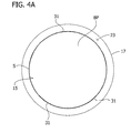
Fig. 4A is a cross-section taken along line 4-4 of the compression garment inFig. 3 , with a bladder of the compression garment inflated. -
Fig. 4B is a cross-section taken along line 4-4 of the compression garment inFig. 3 , with the bladder deflated. -
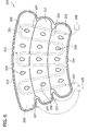
Fig. 5 is a view of an inward side of a compression garment, with a ventilator shown in phantom. -
Fig. 6 is view of an outward side of a compression garment, with a ventilator shown in phantom. -
Fig. 7 is a view of an inward side the compression garment ofFig. 6 . -
Fig. 8 is a view of an outward side of a compression garment, with a ventilator shown in phantom. - Corresponding reference characters indicate corresponding parts throughout the drawings.
- As used herein, the terms "proximal" and "distal" refer to relative locations of components, parts and the like of a compression garment when the garment is worn. For example, a "proximal" component is disposed most adjacent to the wearer's torso, a "distal" component is disposed most distant from the wearer's torso, and an "intermediate" component is disposed generally anywhere between the proximal and distal components. As used herein, ``inward side" and "outward side" refer to the orientation of sides of a compression garment relative to a wearer when the compression garment is worn by the wearer. For example, an "inward side" of a compression garment is a side of the compression garment directed toward a wearer's skin when the compression garment is worn by the wearer, and an "outward side" of the compression garment is a side of the compression garment directed away from the wearer's skin when the compression garment is worn by the wearer.
- Referring to
Figs. 1-3 , acompression garment 11 applies cyclical and sequential compression therapy to a limb of a wearer. As discussed in further detail below, thecompression garment 11 includes aventilator 13 for ventilating the wearer's limb when thecompression garment 11 is worn. Thecompression garment 11 is shown as a knee-length sleeve positionable around the leg of the wearer. It will be understood, however, that thecompression garment 11 may have different configurations such as, for example, a thigh-length sleeve. Compression garments for being disposed about other limbs of the wearer's body are also within the scope of this disclosure. These include, for example, garments that do not apply cyclical compression and/or garments that do not apply sequential compression. - The
compression garment 11 includes aninner bladder layer 15 and anouter bladder layer 17. Theinner bladder layer 15 and theouter bladder layer 17 are secured to one another, with theouter bladder layer 17 overlaid on theinner bladder layer 15. The bladder layers 15, 17 are secured together at aperipheral seam 19 extending generally about aperiphery 21 of thesleeve 11. The bladder layers 15, 17 may be secured together, for example, by radio frequency welding, adhesive, or other chemical and/or mechanical process.Bladders 23 are at least partially defined by bladder seams 24. Thebladders 23 expand and contract under the influence of air pressure or other fluids delivered from a fluid source 25 (e.g., a pump) throughrespective conduits 27 in communication with thefluid source 25 and a respective volume defined by each of thebladders 23. The volume defined by eachbladder 23 defines a compression region of eachrespective bladder 23. The compression region is generally bounded by the bladder seams 24, which provide a fluid tight boundary for the compression region. In some embodiments, thebladders 23 defineopenings 29 extending completely through thebladders 23 to facilitate, for example, removal of moisture away from the wearer's body through theopenings 29. - The inner and outer bladder layers 15, 17 may each include a sheet of elastic material, generally referred to herein as bladder material. For example, the bladder layers 15, 17 can each include a pliable sheet of polyvinyl chloride (PVC). The bladder layers 15, 17 may be secured together at locations other than the bladder seams 24. Additionally or alternatively, the bladder layers 15, 17 may be formed from a single sheet of material folded over itself.
- The
ventilator 13 is at least partially disposed on an inward side of theinner bladder layer 15 for contacting the wearer's skin when thesleeve 11 is worn. Theventilator 13 includes a plurality of spaced apartcompression elements 31 extending in a direction generally from aproximal edge portion 33 of theventilator 13 to adistal edge portion 35 of theventilator 13. The plurality of spaced apartcompression elements 31 form a plurality ofpassages 39 also extending generally from theproximal edge portion 33 of theventilator 13 to thedistal edge portion 35 of theventilator 13. It should be appreciated, however, that thecompression members 31 andpassages 39 can be arranged in other ways. For example, thecompression members 31 andpassages 39 can extend outward in a radial fashion from theopenings 29. - Referring now to
Figs. 1-4B , when thecompression garment 11 is wrapped around a body part BP of the wearer, thepassages 39 are defined by theside walls 36 of thecompression elements 31, the inward side of theinner bladder layer 15, and the wearer's skin S. For example, eachpassage 39 can be a channel substantially open toward the wearer. Thepassages 39 provide ventilation for the wearer's skin S through fluid communication between thepassages 39 and atmospheric air at a location through theopenings 29 in thebladders 23 and/or the proximal anddistal edge portions ventilator 13, as will be explained in greater detail below. - The
compression elements 31 are flexible to collapse under an external compressive force (e.g., a force of inflation of the bladders 23) to collapse the passages 39 (Fig. 4A ). Thecompressive elements 31 are also flexible to resiliently expand thepassages 39 when the external compressive force is removed (e.g., when thebladders 23 are deflated) (Figs. 2 and4B ). - Each
compression elements 31 can have a dome shaped cross-section forming a curvedouter surface 37 disposed toward the wearer's limb when thecompression garment 11 is worn. Additionally or alternatively, eachcompression elements 31 can include an elongate foam member with an open cell volume that collapses under the application of compression pressure and expands upon removal of compression pressure. Alternatively or in addition, eachcompression element 31 may include a flexible tube that collapses under the application of compression pressure and expands upon removal of compression pressure. - In use, the
compression garment 11 is wrapped around the wear's limb, with thebladders 23 typically in a deflated state in which eachbladder 23 is substantially devoid of an inflation fluid. With thebladders 23 in the deflated state, thecompression elements 31 have an expanded configuration such that thepassages 39 are defined between thebladder layer 15 and the wearer's skin S (Fig. 4B ). In the expanded configuration, thepassages 39 are in fluid communication with atmospheric air at theproximal edge portion 33 anddistal edge portion 35 of theventilator 13 and/or through theopenings 29 in thebladders 23. Air can circulate through thepassages 39 when thebladders 23 are deflated and thecompression elements 31 are expanded. For example, if thecompression garment 11 is worn by the wearer, but compression therapy is not being applied to the wearer's body part BP (e.g., prior to treatment or between treatments) air can move through the passages through natural convection. This air circulation can help to keep the wearer's limb cool and reduce moisture build-up between thecompression garment 11 and the wearer's body part BP. - Inflation of the
bladders 23 causes thebladders 23 to swell applying a compression force toward the wearer's body part BP. The compression force applied by thebladders 23 compresses thecompression elements 31 between thebladders 23 and the wearer's body part BP, collapsing the compression elements 31 (Fig. 4A ). Spacing between the body part BP and theinner layer 15 is exaggerated inFig. 4A to illustrate thecollapsed compression elements 31. As thecompression elements 31 are collapsed thepassages 39 are also collapsed expelling air from thepassages 39 to the atmosphere. With thecompression elements 31 collapsed, theinner bladder layer 15 is substantially flat against the wearer's limb BP so that theinflated bladders 23 can uniformly cover the wearer's body part BP except for the locations of theopenings 29. The substantially uniform coverage of thebladders 23 can facilitate application of effective compression therapy to the wearer's body part BP. For example, the substantially uniform coverage of theinflated bladders 23 on the wearer's body part BP can exhibit hemodynamic performance similar to hemodynamic performance a compression garment without thecompression elements 31. - After an inflation phase where the
bladders 23 are inflated, thecompression garment 11 can undergo a deflation phase where thebladders 23 are deflated. During the deflation phase, fluid in thebladders 23 is vented out of thebladders 23, removing the compression force exerted by thebladders 23 on the wearer's body part BP during the inflation phase. The removal of the compression force of thebladders 23 results in expansion of the compression elements 31 (Fig. 4B ). - The
passages 39 open as thebladders 23 deflate and thecompression elements 31 expand. Atmospheric air is drawn into thepassages 39 under a negative pressure caused by the opening thepassages 39. For example, the negative pressure can draw atmospheric air into thepassages 39 at the proximal anddistal edge portions ventilator 13 and/or through theopenings 29 in thebladders 23. Air flows out of thepassages 39 when thecompression elements 31 are compressed. For example, the positive pressure of the expansion of thebladders 23 to compress thecompression elements 31 can be sufficient to compress thepassages 39 to expel air from thepassages 39. Thus, it should be appreciated that the repeated opening and closing of the passages 39 (e.g., resulting from the cyclical inflation and deflation of thebladders 23 during the course of compression therapy) can draw air into thepassages 39 and expel air from thepassages 39 to produce forced convective cooling near the wearer's skin S. - While certain embodiments have been described, other embodiments are possible.
- For example, while compression garments have been described as including ventilators including components in contact with a wearer's limb, other configurations are additionally or alternatively possible. For example, referring to
Fig. 5 , acompression garment 111 includes aninner layer 150. Theinner layer 150 is secured at least to aninner bladder layer 115 at aperipheral seam 119. Theinner layer 150 is disposed over aventilator 113 and, in some embodiments, is not directly secured to theventilator 113. Theinner layer 150 includes a mesh material through which air can easily flow into and out ofpassages 139 defined by theventilator 113. - The
inner layer 150 is disposed for contacting the wTearer's skin when thecompression garment 111 is worn. Theinner layer 150 can be constructed, for example, of a material capable of wicking moisture away from the wearer's skin. For example, theinner layer 150, through capillary action along a yarn filament surface of the layer, can draw in moisture trapped near the skin of the wearer, and carry the moisture away from the surface of the skin, transporting the moisture from locations where the moisture is abundant to areas where moisture is less abundant for evaporation to the ambient environment. For example, moisture may be transported toward areas of theinner layer 150 underneathopenings 129. - As another example, while the compression garments have been described as having ventilators with compression elements that self-expand to draw air into passages, other configurations are additionally or alternatively possible. For example, referring to
Figs. 6 and7 , acompression garment 211 includes aventilator 213 including aninflatable member 231, as described in further detail below. Thecompression sleeve 211 includes aninner bladder layer 215 and anouter bladder layer 217. Theinner bladder layer 215 and theouter bladder layer 217 are secured together at aperipheral seam 219 generally about a periphery 221 of thesleeve 211. Theinner bladder layer 215 and theouter bladder layer 217 are secured together atbladder seams 224 to definebladders 223. Thebladders 223 expand and contract under the influence of air pressure or other fluids delivered from a pump orfluid source 225 throughrespective conduits 227 in communication with thefluid source 225 and a volume defined by thebladders 223. In some embodiments, thebladders 223 defineopenings 229 extending completely through thebladders 223. - A
ventilator 213 is positioned to ventilate the wearer's skin during use of thecompression garment 211. Theventilator 213 includes aninflatable member 231 disposed along theinner bladder layer 215, toward and inward side of thecompression garment 211. Theinflatable member 231 is fluidly connectable to afluid source 260 to inflate theinflatable member 231. Theinflatable member 231 defines a plurality ofperforations 270 through which air can be expelled when theinflatable member 231 is inflated. The combined open area of theperforations 270 is relatively small such that theinflatable member 231 can expand to an extent while air exits through theperforations 270 to cool the wearer's skin. Theinflatable member 231 can have a dome-shaped cross-section when inflated to form a curved outer surface disposed toward the wearer's limb when thecompression garment 211 is worn. Theinflatable member 231 can be deflated to remove fluid from the inflatable member. It should be appreciated that theinflatable member 231 may be a single inflatable member or a plurality of separate and distinct inflatable members. -
Side walls 236 of adjacent sections of theinflatable member 231 and theinner bladder layer 215 define a plurality ofpassages 239. Thepassages 239 provide fluid communication from a compression region defined by thebladders 223 to locations outside of, or out from underneath, thecompression garment 211. For example, the plurality ofpassages 239 can provide fluid communication from the compression region to one or more of the following: theopenings 229 in thebladders 223, and proximal anddistal edge portions ventilator 213, as described in greater detail below. - The
compression garment 211 is wrapped around the wearer's limb and pressurized fluid is delivered throughconduits 227 into thebladders 223 to inflate the bladders. Prior to inflation, thebladders 223 are typically in a deflated state. With thebladders 223 in the deflated state, theinflatable member 231 of theventilator 213 can be inflated such that expansion of theinflatable member 231 defines thepassages 239. It should be appreciated that, when thesleeve 211 is wrapped around the wearer's limb, thepassages 239 are defined by theside walls 236 of theinflatable member 231, the inward side of theinner bladder layer 215, and the wearer's skin. Thepassages 239 provide ventilation for the wearer's skin through fluid communication between thepassages 239 and atmospheric air. - During inflation of the
bladders 223, theinflatable member 231 can be deflated. As theinflatable member 231 deflates thepassages 239 collapse and fluid in the passages is expelled from the passages such that theinflatable member 231 lies substantially flat against theinner bladder layer 215. With theinflatable member 231 deflated, theinflated bladders 223 can uniformly cover the wearer's limb, except for the locations of theopenings 229. The substantially uniform coverage of theinflated bladders 223 on the wearer's limb can facilitate application of effective compression therapy to the wearer's limb. - During deflation of the
bladders 223, theinflatable member 231 can be inflated to open thepassages 239. Atmospheric air is drawn into thepassages 239 under a negative pressure caused by expansion of the volume of thepassages 239. The atmospheric air can be drawn into thepassages 239 at theproximal edge portion 233 and/or thedistal edge portion 235 of theventilator 213 and/or through theopenings 229 in thebladders 223. This circulation of atmospheric air ventilates the wearer's skin underneath thebladders 223, reducing discomfort that can be associated with the buildup of perspiration underneath thebladders 223. - Although a single
inflatable member 231 is shown, other configurations are additionally or alternatively possible. For example, eachbladder 223 may have a dedicated inflatable member that is inflated and deflated in response to the deflation and inflation of a respective bladder. - As yet another example, while compression garments have been described as including inflatable members inflatable by dedicated fluid sources, other configurations are additionally or alternatively possible. For example, referring to
Fig. 8 , acompression garment 311 includesbladders 323 and aventilator 313 including aninflatable member 331. Thebladders 323 andinflatable member 331 may be inflated and deflated by a single fluid source 325 (e.g., a pump) in fluid communication with both thebladders 323 and theinflatable member 331. Operation of thecompression garment 311 is otherwise similar to that ofcompression garment 211. - A number of embodiments have been described. Nevertheless, it will be understood that various modifications may be made without departing from the spirit and scope of the disclosure. Accordingly, other embodiments are within the scope of the following claims.
Claims (12)
- A compression garment comprising:fluid-impermeable bladder layers defining an inflatable bladder cyclically inflatable and deflatable to apply compression pressure to a part of a wearer's body, the inflatable bladder having an inward side and an outward side, the inward side substantially opposite the outward side such that skin of the wearer is closer to the inward side than to the outward side when the compression garment is worn on the wearer's body part; anda ventilator at least partially disposed on the inward side of the inflatable bladder, the ventilator at least partially defining at least one passage between the wearer's skin and the inward side of the bladder and in fluid communication with atmospheric air at a location outside of the compression garment when the compression garment is worn on the wearer's body part, the ventilator flexible to collapse the at least one passage under the force of inflation of the bladder and to resiliently expand the at least one passage upon deflation of the bladder, the collapse of the at least one passage expelling air from the at least one passage to the atmospheric air and the expansion of the at least one passage drawing the atmospheric air into the at least one passage.
- The compression garment of claim 1, wherein the inflatable bladder defines at least one aperture extending through the bladder from the outward side to the inward side, the at least one passage in fluid communication with said at least one aperture.
- The compression garment of any of the preceding claims, wherein the ventilator comprises foam at least partially defining the at least one passage.
- The compression garment of any of the preceding claims, wherein the at least one passage is a plurality of spaced apart channels.
- The compression garment of any of the preceding claims, wherein the ventilator comprises spaced apart compression elements in mechanical communication with the inflatable bladder to transmit force from the inflatable bladder to the wearer's body when the compression garment is worn on the wearer's body.
- The compression garment of claim 5, wherein the at least one passage includes opposite side walls, and the compression elements define the side walls of the at least one passage.
- The compression garment of claim 6, wherein the compression elements comprise elongate tubes disposed along the inward side of the bladder.
- The compression garment of claim 7, wherein the elongate tubes each have a curved surface disposed toward the wearer's body part when the compression garment is worn on the wearer's body part.
- The compression garment of any of the preceding claims, further comprising a wicking layer disposed between the wearer's skin and the ventilator when the compression garment is worn on the wearer's body part.
- The compression garment of claim 9, wherein the wicking layer is secured at least around a perimeter of the inflatable bladder.
- The compression garment of claim 9, wherein the wicking layer is unsecured to the at least one passage.
- The compression garment of any of the preceding claims, wherein the ventilator has a proximal edge portion and a distal edge portion, the passage extending to at least one of the proximal and distal edge portions for fluid communication with the location outside of the compression garment when the passage expands upon deflation of the bladder.
Applications Claiming Priority (1)
| Application Number | Priority Date | Filing Date | Title |
|---|---|---|---|
| US14/040,193 US20150094628A1 (en) | 2013-09-27 | 2013-09-27 | Compression garment ventilation |
Publications (2)
| Publication Number | Publication Date |
|---|---|
| EP2853251A1 true EP2853251A1 (en) | 2015-04-01 |
| EP2853251B1 EP2853251B1 (en) | 2016-08-24 |
Family
ID=51626417
Family Applications (1)
| Application Number | Title | Priority Date | Filing Date |
|---|---|---|---|
| EP14186599.8A Not-in-force EP2853251B1 (en) | 2013-09-27 | 2014-09-26 | Compression garment ventilation |
Country Status (3)
| Country | Link |
|---|---|
| US (1) | US20150094628A1 (en) |
| EP (1) | EP2853251B1 (en) |
| AU (1) | AU2014221323B2 (en) |
Cited By (1)
| Publication number | Priority date | Publication date | Assignee | Title |
|---|---|---|---|---|
| CN105167905A (en) * | 2015-10-23 | 2015-12-23 | 河北工程大学 | Massaging and heating abdomen recovery instrument special for pregnant woman |
Families Citing this family (4)
| Publication number | Priority date | Publication date | Assignee | Title |
|---|---|---|---|---|
| IL281467A (en) * | 2021-03-14 | 2022-10-01 | Mego Afek Ac Ltd | Massage sleeve with ventilation capability |
| US11844918B2 (en) * | 2021-04-25 | 2023-12-19 | Tri.O Medical Device Ltd | Apparatus for use with a pressure-regulating device |
| USD1086473S1 (en) * | 2021-06-03 | 2025-07-29 | Hyperice Ip Subco, Llc | Air bladder |
| CN115737390A (en) * | 2022-11-02 | 2023-03-07 | 宫和健康科技(上海)有限公司 | Limb massager and massage chair |
Citations (2)
| Publication number | Priority date | Publication date | Assignee | Title |
|---|---|---|---|---|
| US4343302A (en) * | 1978-10-30 | 1982-08-10 | Dillon Richard S | Promoting circulation of blood |
| US4453538A (en) * | 1977-04-07 | 1984-06-12 | Whitney John K | Medical apparatus |
Family Cites Families (7)
| Publication number | Priority date | Publication date | Assignee | Title |
|---|---|---|---|---|
| US3148391A (en) * | 1961-11-24 | 1964-09-15 | John K Whitney | Support device |
| US4091804A (en) * | 1976-12-10 | 1978-05-30 | The Kendall Company | Compression sleeve |
| JPS6080452A (en) * | 1983-10-11 | 1985-05-08 | 株式会社精研 | Air mat apparatus |
| DE3672939D1 (en) * | 1985-04-15 | 1990-08-30 | Pauline De Looper | BEDDING OR SEAT PART. |
| US8162861B2 (en) * | 2007-04-09 | 2012-04-24 | Tyco Healthcare Group Lp | Compression device with strategic weld construction |
| US20120316480A1 (en) * | 2010-08-12 | 2012-12-13 | Sun Scientific, Inc. | Therapeutic compression apparatus |
| ES2913287T3 (en) * | 2010-10-05 | 2022-06-01 | Dabir Surfaces Inc | Apparatus, system and method of support |
-
2013
- 2013-09-27 US US14/040,193 patent/US20150094628A1/en not_active Abandoned
-
2014
- 2014-09-10 AU AU2014221323A patent/AU2014221323B2/en not_active Ceased
- 2014-09-26 EP EP14186599.8A patent/EP2853251B1/en not_active Not-in-force
Patent Citations (2)
| Publication number | Priority date | Publication date | Assignee | Title |
|---|---|---|---|---|
| US4453538A (en) * | 1977-04-07 | 1984-06-12 | Whitney John K | Medical apparatus |
| US4343302A (en) * | 1978-10-30 | 1982-08-10 | Dillon Richard S | Promoting circulation of blood |
Cited By (1)
| Publication number | Priority date | Publication date | Assignee | Title |
|---|---|---|---|---|
| CN105167905A (en) * | 2015-10-23 | 2015-12-23 | 河北工程大学 | Massaging and heating abdomen recovery instrument special for pregnant woman |
Also Published As
| Publication number | Publication date |
|---|---|
| US20150094628A1 (en) | 2015-04-02 |
| EP2853251B1 (en) | 2016-08-24 |
| AU2014221323B2 (en) | 2015-06-04 |
| AU2014221323A1 (en) | 2015-04-16 |
Similar Documents
| Publication | Publication Date | Title |
|---|---|---|
| EP2853251B1 (en) | Compression garment ventilation | |
| US9205021B2 (en) | Compression system with vent cooling feature | |
| KR102206545B1 (en) | Pressure cuff or garment | |
| EP1795168B1 (en) | Compression apparatus | |
| TW408016B (en) | Device for applying pressure to a body limb; slipper, knee protector, pressure suit comprising the device, method for immobilizing a fractured bone in a limb, and method of massaging a limb of the body of an individual | |
| US8029451B2 (en) | Compression sleeve having air conduits | |
| EP1795167B1 (en) | Compression sleeve having air conduit | |
| JP2004526538A5 (en) | ||
| CN102440893B (en) | Bladder tube connection | |
| JP2009153995A (en) | External counterpulsation cardiac assist device | |
| US8801644B2 (en) | Pneumatic compression garment with noise attenuation | |
| JP2010528704A (en) | Control device for limb high pressure device | |
| TWI488617B (en) | Compression garment including bladder having reduced inflatable volume | |
| EP3416606B1 (en) | Compression therapy device | |
| US20140276286A1 (en) | Non-Woven Garment For Deep Vein Thrombosis Prevention | |
| JP2011015896A (en) | External counterpulsation apparatus |
Legal Events
| Date | Code | Title | Description |
|---|---|---|---|
| PUAI | Public reference made under article 153(3) epc to a published international application that has entered the european phase |
Free format text: ORIGINAL CODE: 0009012 |
|
| 17P | Request for examination filed |
Effective date: 20140926 |
|
| AK | Designated contracting states |
Kind code of ref document: A1 Designated state(s): AL AT BE BG CH CY CZ DE DK EE ES FI FR GB GR HR HU IE IS IT LI LT LU LV MC MK MT NL NO PL PT RO RS SE SI SK SM TR |
|
| AX | Request for extension of the european patent |
Extension state: BA ME |
|
| R17P | Request for examination filed (corrected) |
Effective date: 20150831 |
|
| RBV | Designated contracting states (corrected) |
Designated state(s): AL AT BE BG CH CY CZ DE DK EE ES FI FR GB GR HR HU IE IS IT LI LT LU LV MC MK MT NL NO PL PT RO RS SE SI SK SM TR |
|
| RIC1 | Information provided on ipc code assigned before grant |
Ipc: A61H 9/00 20060101AFI20151126BHEP Ipc: A61H 23/04 20060101ALI20151126BHEP |
|
| GRAP | Despatch of communication of intention to grant a patent |
Free format text: ORIGINAL CODE: EPIDOSNIGR1 |
|
| INTG | Intention to grant announced |
Effective date: 20160502 |
|
| GRAS | Grant fee paid |
Free format text: ORIGINAL CODE: EPIDOSNIGR3 |
|
| GRAA | (expected) grant |
Free format text: ORIGINAL CODE: 0009210 |
|
| AK | Designated contracting states |
Kind code of ref document: B1 Designated state(s): AL AT BE BG CH CY CZ DE DK EE ES FI FR GB GR HR HU IE IS IT LI LT LU LV MC MK MT NL NO PL PT RO RS SE SI SK SM TR |
|
| REG | Reference to a national code |
Ref country code: GB Ref legal event code: FG4D |
|
| REG | Reference to a national code |
Ref country code: CH Ref legal event code: EP |
|
| REG | Reference to a national code |
Ref country code: AT Ref legal event code: REF Ref document number: 822387 Country of ref document: AT Kind code of ref document: T Effective date: 20160915 |
|
| REG | Reference to a national code |
Ref country code: IE Ref legal event code: FG4D Ref country code: FR Ref legal event code: PLFP Year of fee payment: 3 |
|
| REG | Reference to a national code |
Ref country code: DE Ref legal event code: R096 Ref document number: 602014003236 Country of ref document: DE |
|
| REG | Reference to a national code |
Ref country code: LT Ref legal event code: MG4D |
|
| REG | Reference to a national code |
Ref country code: NL Ref legal event code: MP Effective date: 20160824 |
|
| REG | Reference to a national code |
Ref country code: AT Ref legal event code: MK05 Ref document number: 822387 Country of ref document: AT Kind code of ref document: T Effective date: 20160824 |
|
| PG25 | Lapsed in a contracting state [announced via postgrant information from national office to epo] |
Ref country code: LT Free format text: LAPSE BECAUSE OF FAILURE TO SUBMIT A TRANSLATION OF THE DESCRIPTION OR TO PAY THE FEE WITHIN THE PRESCRIBED TIME-LIMIT Effective date: 20160824 Ref country code: RS Free format text: LAPSE BECAUSE OF FAILURE TO SUBMIT A TRANSLATION OF THE DESCRIPTION OR TO PAY THE FEE WITHIN THE PRESCRIBED TIME-LIMIT Effective date: 20160824 Ref country code: NL Free format text: LAPSE BECAUSE OF FAILURE TO SUBMIT A TRANSLATION OF THE DESCRIPTION OR TO PAY THE FEE WITHIN THE PRESCRIBED TIME-LIMIT Effective date: 20160824 Ref country code: IT Free format text: LAPSE BECAUSE OF FAILURE TO SUBMIT A TRANSLATION OF THE DESCRIPTION OR TO PAY THE FEE WITHIN THE PRESCRIBED TIME-LIMIT Effective date: 20160824 Ref country code: HR Free format text: LAPSE BECAUSE OF FAILURE TO SUBMIT A TRANSLATION OF THE DESCRIPTION OR TO PAY THE FEE WITHIN THE PRESCRIBED TIME-LIMIT Effective date: 20160824 Ref country code: FI Free format text: LAPSE BECAUSE OF FAILURE TO SUBMIT A TRANSLATION OF THE DESCRIPTION OR TO PAY THE FEE WITHIN THE PRESCRIBED TIME-LIMIT Effective date: 20160824 Ref country code: NO Free format text: LAPSE BECAUSE OF FAILURE TO SUBMIT A TRANSLATION OF THE DESCRIPTION OR TO PAY THE FEE WITHIN THE PRESCRIBED TIME-LIMIT Effective date: 20161124 |
|
| PG25 | Lapsed in a contracting state [announced via postgrant information from national office to epo] |
Ref country code: ES Free format text: LAPSE BECAUSE OF FAILURE TO SUBMIT A TRANSLATION OF THE DESCRIPTION OR TO PAY THE FEE WITHIN THE PRESCRIBED TIME-LIMIT Effective date: 20160824 Ref country code: BE Free format text: LAPSE BECAUSE OF NON-PAYMENT OF DUE FEES Effective date: 20160930 Ref country code: PT Free format text: LAPSE BECAUSE OF FAILURE TO SUBMIT A TRANSLATION OF THE DESCRIPTION OR TO PAY THE FEE WITHIN THE PRESCRIBED TIME-LIMIT Effective date: 20161226 Ref country code: LV Free format text: LAPSE BECAUSE OF FAILURE TO SUBMIT A TRANSLATION OF THE DESCRIPTION OR TO PAY THE FEE WITHIN THE PRESCRIBED TIME-LIMIT Effective date: 20160824 Ref country code: AT Free format text: LAPSE BECAUSE OF FAILURE TO SUBMIT A TRANSLATION OF THE DESCRIPTION OR TO PAY THE FEE WITHIN THE PRESCRIBED TIME-LIMIT Effective date: 20160824 Ref country code: GR Free format text: LAPSE BECAUSE OF FAILURE TO SUBMIT A TRANSLATION OF THE DESCRIPTION OR TO PAY THE FEE WITHIN THE PRESCRIBED TIME-LIMIT Effective date: 20161125 Ref country code: SE Free format text: LAPSE BECAUSE OF FAILURE TO SUBMIT A TRANSLATION OF THE DESCRIPTION OR TO PAY THE FEE WITHIN THE PRESCRIBED TIME-LIMIT Effective date: 20160824 |
|
| PG25 | Lapsed in a contracting state [announced via postgrant information from national office to epo] |
Ref country code: EE Free format text: LAPSE BECAUSE OF FAILURE TO SUBMIT A TRANSLATION OF THE DESCRIPTION OR TO PAY THE FEE WITHIN THE PRESCRIBED TIME-LIMIT Effective date: 20160824 Ref country code: RO Free format text: LAPSE BECAUSE OF FAILURE TO SUBMIT A TRANSLATION OF THE DESCRIPTION OR TO PAY THE FEE WITHIN THE PRESCRIBED TIME-LIMIT Effective date: 20160824 |
|
| REG | Reference to a national code |
Ref country code: DE Ref legal event code: R097 Ref document number: 602014003236 Country of ref document: DE |
|
| PG25 | Lapsed in a contracting state [announced via postgrant information from national office to epo] |
Ref country code: SM Free format text: LAPSE BECAUSE OF FAILURE TO SUBMIT A TRANSLATION OF THE DESCRIPTION OR TO PAY THE FEE WITHIN THE PRESCRIBED TIME-LIMIT Effective date: 20160824 Ref country code: SK Free format text: LAPSE BECAUSE OF FAILURE TO SUBMIT A TRANSLATION OF THE DESCRIPTION OR TO PAY THE FEE WITHIN THE PRESCRIBED TIME-LIMIT Effective date: 20160824 Ref country code: DK Free format text: LAPSE BECAUSE OF FAILURE TO SUBMIT A TRANSLATION OF THE DESCRIPTION OR TO PAY THE FEE WITHIN THE PRESCRIBED TIME-LIMIT Effective date: 20160824 Ref country code: BG Free format text: LAPSE BECAUSE OF FAILURE TO SUBMIT A TRANSLATION OF THE DESCRIPTION OR TO PAY THE FEE WITHIN THE PRESCRIBED TIME-LIMIT Effective date: 20161124 Ref country code: BE Free format text: LAPSE BECAUSE OF FAILURE TO SUBMIT A TRANSLATION OF THE DESCRIPTION OR TO PAY THE FEE WITHIN THE PRESCRIBED TIME-LIMIT Effective date: 20160824 Ref country code: CZ Free format text: LAPSE BECAUSE OF FAILURE TO SUBMIT A TRANSLATION OF THE DESCRIPTION OR TO PAY THE FEE WITHIN THE PRESCRIBED TIME-LIMIT Effective date: 20160824 Ref country code: PL Free format text: LAPSE BECAUSE OF FAILURE TO SUBMIT A TRANSLATION OF THE DESCRIPTION OR TO PAY THE FEE WITHIN THE PRESCRIBED TIME-LIMIT Effective date: 20160824 |
|
| REG | Reference to a national code |
Ref country code: IE Ref legal event code: MM4A |
|
| PG25 | Lapsed in a contracting state [announced via postgrant information from national office to epo] |
Ref country code: MC Free format text: LAPSE BECAUSE OF FAILURE TO SUBMIT A TRANSLATION OF THE DESCRIPTION OR TO PAY THE FEE WITHIN THE PRESCRIBED TIME-LIMIT Effective date: 20160824 |
|
| PLBE | No opposition filed within time limit |
Free format text: ORIGINAL CODE: 0009261 |
|
| STAA | Information on the status of an ep patent application or granted ep patent |
Free format text: STATUS: NO OPPOSITION FILED WITHIN TIME LIMIT |
|
| PG25 | Lapsed in a contracting state [announced via postgrant information from national office to epo] |
Ref country code: IE Free format text: LAPSE BECAUSE OF NON-PAYMENT OF DUE FEES Effective date: 20160926 |
|
| 26N | No opposition filed |
Effective date: 20170526 |
|
| REG | Reference to a national code |
Ref country code: FR Ref legal event code: PLFP Year of fee payment: 4 |
|
| PG25 | Lapsed in a contracting state [announced via postgrant information from national office to epo] |
Ref country code: SI Free format text: LAPSE BECAUSE OF FAILURE TO SUBMIT A TRANSLATION OF THE DESCRIPTION OR TO PAY THE FEE WITHIN THE PRESCRIBED TIME-LIMIT Effective date: 20160824 Ref country code: LU Free format text: LAPSE BECAUSE OF NON-PAYMENT OF DUE FEES Effective date: 20160926 |
|
| REG | Reference to a national code |
Ref country code: GB Ref legal event code: 732E Free format text: REGISTERED BETWEEN 20180208 AND 20180214 |
|
| REG | Reference to a national code |
Ref country code: CH Ref legal event code: PL |
|
| PG25 | Lapsed in a contracting state [announced via postgrant information from national office to epo] |
Ref country code: HU Free format text: LAPSE BECAUSE OF FAILURE TO SUBMIT A TRANSLATION OF THE DESCRIPTION OR TO PAY THE FEE WITHIN THE PRESCRIBED TIME-LIMIT; INVALID AB INITIO Effective date: 20140926 |
|
| PG25 | Lapsed in a contracting state [announced via postgrant information from national office to epo] |
Ref country code: CY Free format text: LAPSE BECAUSE OF FAILURE TO SUBMIT A TRANSLATION OF THE DESCRIPTION OR TO PAY THE FEE WITHIN THE PRESCRIBED TIME-LIMIT Effective date: 20160824 Ref country code: MK Free format text: LAPSE BECAUSE OF FAILURE TO SUBMIT A TRANSLATION OF THE DESCRIPTION OR TO PAY THE FEE WITHIN THE PRESCRIBED TIME-LIMIT Effective date: 20160824 Ref country code: IS Free format text: LAPSE BECAUSE OF FAILURE TO SUBMIT A TRANSLATION OF THE DESCRIPTION OR TO PAY THE FEE WITHIN THE PRESCRIBED TIME-LIMIT Effective date: 20160824 Ref country code: MT Free format text: LAPSE BECAUSE OF NON-PAYMENT OF DUE FEES Effective date: 20160930 |
|
| PG25 | Lapsed in a contracting state [announced via postgrant information from national office to epo] |
Ref country code: LI Free format text: LAPSE BECAUSE OF NON-PAYMENT OF DUE FEES Effective date: 20170930 Ref country code: CH Free format text: LAPSE BECAUSE OF NON-PAYMENT OF DUE FEES Effective date: 20170930 |
|
| REG | Reference to a national code |
Ref country code: FR Ref legal event code: PLFP Year of fee payment: 5 |
|
| PG25 | Lapsed in a contracting state [announced via postgrant information from national office to epo] |
Ref country code: AL Free format text: LAPSE BECAUSE OF FAILURE TO SUBMIT A TRANSLATION OF THE DESCRIPTION OR TO PAY THE FEE WITHIN THE PRESCRIBED TIME-LIMIT Effective date: 20160824 Ref country code: TR Free format text: LAPSE BECAUSE OF FAILURE TO SUBMIT A TRANSLATION OF THE DESCRIPTION OR TO PAY THE FEE WITHIN THE PRESCRIBED TIME-LIMIT Effective date: 20160824 |
|
| PGFP | Annual fee paid to national office [announced via postgrant information from national office to epo] |
Ref country code: GB Payment date: 20200928 Year of fee payment: 7 Ref country code: FR Payment date: 20200925 Year of fee payment: 7 Ref country code: DE Payment date: 20200929 Year of fee payment: 7 |
|
| REG | Reference to a national code |
Ref country code: DE Ref legal event code: R119 Ref document number: 602014003236 Country of ref document: DE |
|
| GBPC | Gb: european patent ceased through non-payment of renewal fee |
Effective date: 20210926 |
|
| PG25 | Lapsed in a contracting state [announced via postgrant information from national office to epo] |
Ref country code: GB Free format text: LAPSE BECAUSE OF NON-PAYMENT OF DUE FEES Effective date: 20210926 Ref country code: FR Free format text: LAPSE BECAUSE OF NON-PAYMENT OF DUE FEES Effective date: 20210930 Ref country code: DE Free format text: LAPSE BECAUSE OF NON-PAYMENT OF DUE FEES Effective date: 20220401 |