EP2853085B1 - Rescreeining selected parts of a halftone image - Google Patents
Rescreeining selected parts of a halftone image Download PDFInfo
- Publication number
- EP2853085B1 EP2853085B1 EP13727451.0A EP13727451A EP2853085B1 EP 2853085 B1 EP2853085 B1 EP 2853085B1 EP 13727451 A EP13727451 A EP 13727451A EP 2853085 B1 EP2853085 B1 EP 2853085B1
- Authority
- EP
- European Patent Office
- Prior art keywords
- dots
- dot
- halftone image
- halftone
- size
- Prior art date
- Legal status (The legal status is an assumption and is not a legal conclusion. Google has not performed a legal analysis and makes no representation as to the accuracy of the status listed.)
- Active
Links
Images




Classifications
-
- H—ELECTRICITY
- H04—ELECTRIC COMMUNICATION TECHNIQUE
- H04N—PICTORIAL COMMUNICATION, e.g. TELEVISION
- H04N1/00—Scanning, transmission or reproduction of documents or the like, e.g. facsimile transmission; Details thereof
- H04N1/40—Picture signal circuits
- H04N1/405—Halftoning, i.e. converting the picture signal of a continuous-tone original into a corresponding signal showing only two levels
-
- H—ELECTRICITY
- H04—ELECTRIC COMMUNICATION TECHNIQUE
- H04N—PICTORIAL COMMUNICATION, e.g. TELEVISION
- H04N1/00—Scanning, transmission or reproduction of documents or the like, e.g. facsimile transmission; Details thereof
- H04N1/40—Picture signal circuits
- H04N1/407—Control or modification of tonal gradation or of extreme levels, e.g. background level
Definitions
- the present invention relates to the field of graphic arts, printing and publishing technologies, specifically, to image reproduction systems characterized by limited numbers of levels of optical parameters.
- the imaging device for example, a laser based imager is capable of producing a limited number of levels representing optical parameter (in most common cases only two levels are used - black and white). This goal is achieved by applying a process called screening, wherein a gray tone value which represents a pixel to be screened in the original image is simulated by means of varying relative area covered by dark elements (pixels) as compared to light elements.
- a screening method An area of an image is reproduced by subdividing it into equal, periodically repeated sub-areas called mesh cells, containing variable-size dark elements (printing dots, alternatively called halftone dots). Relative area coverage is defined as ratio of dark element area to a mesh cell area.
- Such screening method is commonly called Amplitude Modulation (AM) screening.
- AM Amplitude Modulation
- Such screen with a regular, usually square grid structure, is characterized by a screen period and a screen angle. The reciprocal of this period is called screen frequency or screen ruling.
- the size of the smallest halftone printing dot on a printing plate that can be consistently reproduced on press is usually around 40 microns in size. Below this size, halftone dots tend to print unevenly, and may also include drastic increase in size and produce large blot artifacts, or not printing at all.
- 40 micron halftone dot corresponds to area coverage of 3%; for line ruling 1500 lpi, it corresponds to area coverage around 4%. This may result in discontinuity, with annoying artifacts in certain cases especially in the highlight parts of printed images.
- the high dot gain that is associated with flexographic printing process enhances the effect and exacerbates the problem.
- the minimal halftone printing dot that can be reproduced consistently can often be as small as 10 micron.
- the same fundamental problem discussed above exists.
- FM Frequency Modulation
- dot size is kept constant but dot number is modulated as a function of tone value; accuracy of tone representation being defined by predefined minimal halftone dot size and count of halftone dot centers in supercell threshold matrix.
- the supercell-based pattern is prone to grainy and "noisy" appearance; relatively rough quantization steps limited by number of halftone dot centers in a supercell threshold matrix may produce banding effects in vignette parts of image; "orphaned” and incomplete halftone dots still may produce undesirable "blot-like” artifacts; and supercell-based approach limits available number of screen angle/screen frequency combinations to those with rational tangent angles.
- US 5 892 588 A shows a method for halftoning a digital image which applies a conventional cluster dot halftoning method in darker image regions and a dot frequency modulating halftoning method in lighter image regions.
- the dot frequency modulation uses a random number generator to decide where dots should be printed in the lighter image regions.
- a method for enhancing appearance of a halftone image for imaging on a flexographic plate includes retrieving the halftone image from a data storage device; setting a minimal dot size value for printing; analyzing the halftone image with a computer; detecting areas in the halftone image populated with a plurality of dots smaller than the minimal dot size value; replacing the plurality of dots with a reduced set of dots wherein each of the reduced set of dots are larger in size than the plurality of dots and wherein each of the reduced set of dots maintains an original geometric characteristics of the plurality of dots; and saving the reduced set of dots to a storage device.
- a halftone image already screened by means of traditional Amplitude Modulation (AM) screening is conceptually represented as rectangular array of black and white pixels.
- the present invention is not limited by any specific type, algorithm or method of AM screening and utilizes only two basic characteristics of AM screening, namely parameters of a periodic grid, its angle and its frequency represented by its line ruling, i.e. mesh, and derived parameter such as res/mesh ratio, equal to side length of single mesh cell in units of single pixel size.
- the screened image 204 is fetched from storage element 132 ( FIG. 1 ) by computer 130.
- a "natural" system of coordinates is defined, where X axis runs along image lines and Y axis is perpendicular to Y axis, and unit of measure is single pixel size, and its "shifted" system of coordinates, where X' axis and Y' axis run along mesh grid directions that is, rotated by screen angle related to natural system of coordinates and unit of measure stated res/mesh ratio.
- size of halftone dot DS is ⁇ DS2
- F(DS, mx, my) is applied, which returns 1 or 0 in such a way that average value (1/Nds) ⁇ F(DS, mx, my) *DS2, where sum is done for all halftone dots of size DS, is substantially equal to DS.
- Operator F can be analytical expression or simple lookup operation into predefined array.
- This method ensures both consistent reproduction of halftone dots in regions with extreme values of tone scale via printing process and smooth, non-grainy, artifact-free appearance of said regions and transition regions from extreme values of tone scale to midtone ones.
- an array of values[DSn1,DSn2,...,DSnN] contains four elements - DSn1, DSn2, DSN3 and DSn4 such that the size of element DSn1 is equal to DS1, minimal reliably reproducible halftone dot size (in pixels); size of elements DSn2, DSn3 and DSn4 is DS1+1, DS1+2 and DS1+3 pixels, respectively.
- Cutoff size DS2 in a preferred embodiment is defined as DS1+2 pixels.
- F(DS, mx, my) in the preferred embodiment is defined as a compare operation of a value derived from halftone dot size DS with a value from square lookup array B[N][N] where array size N is 2 ⁇ n, n>>8.
- FIG. 3 shows the halftone image after enhancement.
- Numeral 304 shows an area of dots 304 which replaced the area of dots 204.
- the replaced dots 304 include a smaller number of dots compared to dots 204 which originally populated the area in FIG. 2 .
- Each of the newly created dots 304 are larger in size than the original dots 204 and maintain the geometric characteristics of the dots 304 in terms such as center of gravity and angle.
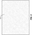
- FIG. 4 shows a zoomed in area of small dots 404, wherein FIG. 5 shows dots 504 which are replacing dots 404. It can seen much more clearly that the number of the replaced dots are fewer and each of the new dots 504 is larger than the original dots 404, however the geometrical layout of the dots 504 is maintained to be similar to the those shown for dots 404.
- FIG. 1 shows an imaging system 100.
- the imaging system 100 includes an imaging carriage 112 mounted on an imaging head 120.
- the imaging head 120 is configured to image on a flexographic plate 108 mounted on a rotating cylinder 104.
- the carriage 112 is adapted to move substantially in parallel to cylinder 104 guided by an advancement screw 116.
- the enhanced halftone 304 is delivered by controller 128 from computer 130 to imaging head 120 of imaging system 100, and is further exposed on flexographic plate 108, by imaging system 100 to form imaged flexographic plate.
Landscapes
- Engineering & Computer Science (AREA)
- Multimedia (AREA)
- Signal Processing (AREA)
- Image Processing (AREA)
- Facsimile Image Signal Circuits (AREA)
Description
- The present invention relates to the field of graphic arts, printing and publishing technologies, specifically, to image reproduction systems characterized by limited numbers of levels of optical parameters.
- In graphic arts technology there is a need for reproduction of continuous tone images by an imaging device. The imaging device, for example, a laser based imager is capable of producing a limited number of levels representing optical parameter (in most common cases only two levels are used - black and white). This goal is achieved by applying a process called screening, wherein a gray tone value which represents a pixel to be screened in the original image is simulated by means of varying relative area covered by dark elements (pixels) as compared to light elements.
- Different screening methods exist. In one of the most common, an area of an image is reproduced by subdividing it into equal, periodically repeated sub-areas called mesh cells, containing variable-size dark elements (printing dots, alternatively called halftone dots). Relative area coverage is defined as ratio of dark element area to a mesh cell area. Such screening method is commonly called Amplitude Modulation (AM) screening. Such screen, with a regular, usually square grid structure, is characterized by a screen period and a screen angle. The reciprocal of this period is called screen frequency or screen ruling.
- Particular problems arise when reproducing characteristics of printing dots which are size dependant. Examples of such processes are flexographic, offset and xerographic printing processes.
- In flexographic printing, the size of the smallest halftone printing dot on a printing plate that can be consistently reproduced on press is usually around 40 microns in size. Below this size, halftone dots tend to print unevenly, and may also include drastic increase in size and produce large blot artifacts, or not printing at all. For commonly used line ruling of 120 lpi and commonly used device resolutions of 2400 or 2540 dpi, 40 micron halftone dot corresponds to area coverage of 3%; for line ruling 1500 lpi, it corresponds to area coverage around 4%. This may result in discontinuity, with annoying artifacts in certain cases especially in the highlight parts of printed images. The high dot gain that is associated with flexographic printing process enhances the effect and exacerbates the problem.
- In the offset printing process, the minimal halftone printing dot that can be reproduced consistently can often be as small as 10 micron. For lower quality paper and high-speed printing presses, for example, in newspaper printing, the same fundamental problem discussed above exists. A similar situation exists in electro-photographic printing, wherein minimal printing dot size is often defined by physical characteristics of toner particles.
- One solution for the above problems is using Frequency Modulation (FM) screening techniques with controlled minimal dot size, so-called "green noise" frequency modulation, shown in
U.S. Pat. No. 5,689,623 (Pinard ), or with controlled midtone clustering, so-called "second order" frequency modulation, shown inU.S. Pat. No. 5,579,457 (Hall ). While solving the problem of highlight region reproduction, frequency modulation introduces its own drawbacks. Relatively rough feature size needed for proper highlights reproduction, often leads to grainy appearance both in highlights and in the midtones areas. Additionally, high circumference-to-area ratio inherent for FM generated printing dots leads to significantly higher dot gain compared to AM halftone screening. Considering that flexographic printing process is already characterized by high dot gain, FM screening may lead to significant contraction of the dynamic range for printed images. - Another solution is known as the "double dot" technique or "Respi screen." According to this technique, the extremes of tone scale, highlights and/or shadows, are rendered with halftone dots that are laid on a grid with the same angle, but with the frequency of the square root of the halftones in the rest of tone scale, thus halving the number of halftone dot and, consequently, doubling the size of each dot. This renders the transition area between extreme and main part of tone scale with halftone dots of two different sizes placed in checkerboard pattern. While moving the cutoff value for non reproducible part of the image farther to extreme parts of tone scale, it still does not completely solve the problem. Moreover, by introducing additional screen frequencies, such technique may produce highly undesirable moire effects in multi-colored images in case of regions where part of color separations are in extreme parts of the tone scale and other separations are in non-extreme part of the color scale.
- In order to overcome the deficiencies above stated, an approach was proposed by
U.S. Pat. No. 5,766,807 (Delabastita et al. ). This method is known as "hybrid screening." In this approach, a "supercell" threshold matrix suitable for periodically tiling a plane is defined in such a way that it contains a plurality of locations for halftone dot centers and is filled with threshold values. When the matrix is used for screening a contone image, in the extreme parts of the tone scale halftone dot of predefined minimal size are produced, whereas in the remaining part of halftone dot centers no halftone dot are produced at all. This is performed in such a way that the area coverage for a whole supercell area corresponds to a tone value in the contone image. In other words, instead of modulating halftone dot size, below predefined dot percentage, dot size is kept constant but dot number is modulated as a function of tone value; accuracy of tone representation being defined by predefined minimal halftone dot size and count of halftone dot centers in supercell threshold matrix. - While free of most undesirable effects of previous solutions, this approach still has some problems. Notably, the supercell-based pattern is prone to grainy and "noisy" appearance; relatively rough quantization steps limited by number of halftone dot centers in a supercell threshold matrix may produce banding effects in vignette parts of image; "orphaned" and incomplete halftone dots still may produce undesirable "blot-like" artifacts; and supercell-based approach limits available number of screen angle/screen frequency combinations to those with rational tangent angles.
- Attention is drawn to
US 5 892 588 A , which shows a method for halftoning a digital image which applies a conventional cluster dot halftoning method in darker image regions and a dot frequency modulating halftoning method in lighter image regions. The dot frequency modulation uses a random number generator to decide where dots should be printed in the lighter image regions. - In accordance with the present invention, a method as set forth in claim 1 is provided. Further embodiments are inter alia disclosed in the dependent claims. Briefly, according to one aspect of the present invention a method for enhancing appearance of a halftone image for imaging on a flexographic plate includes retrieving the halftone image from a data storage device; setting a minimal dot size value for printing; analyzing the halftone image with a computer; detecting areas in the halftone image populated with a plurality of dots smaller than the minimal dot size value; replacing the plurality of dots with a reduced set of dots wherein each of the reduced set of dots are larger in size than the plurality of dots and wherein each of the reduced set of dots maintains an original geometric characteristics of the plurality of dots; and saving the reduced set of dots to a storage device.
- The invention and its objects and advantages will become more apparent in the detailed description of the preferred embodiment presented below.
-
-
FIG. 1 represents in diagrammatic form a prior art imaging system adapted to expose flexographic plates; -
FIG. 2 represents in diagrammatic form a prior art halftone image ready to be exposed; -
FIG. 3 represents in diagrammatic form an enhanced halftone image, enhancing the image shown inFIG. 2 ; -
FIG. 4 represents in diagrammatic form a small dots area from a halftone image to be enhanced; and -
FIG. 5 show in diagrammatic form enhanced area of small dots shown inFIG. 4 , the small dots were replaced with a set of fewer dots wherein each new dot is larger in size. - In the following detailed description, specific details are set forth in order to provide a thorough understanding of the disclosure. However, it will be understood by those skilled in the art that the teachings of the present disclosure may be practiced without these specific details. In other instances, well-known methods, procedures, components and circuits have not been described in detail so as not to obscure the teachings of the present disclosure.
- While the present invention is described in connection with one of the embodiments, it will be understood that it is not intended to limit the invention to this embodiment. On the contrary, it is intended to cover all alternatives and modifications as covered by the appended claims.
- In order to improve the reproduction characteristics of a halftoned image by of controlling halftone dot size and spatial distribution in extreme tone scale parts of said image, a halftone image already screened by means of traditional Amplitude Modulation (AM) screening is conceptually represented as rectangular array of black and white pixels. The present invention is not limited by any specific type, algorithm or method of AM screening and utilizes only two basic characteristics of AM screening, namely parameters of a periodic grid, its angle and its frequency represented by its line ruling, i.e. mesh, and derived parameter such as res/mesh ratio, equal to side length of single mesh cell in units of single pixel size.
- In order to process the screened
image 204 shown inFIG. 2 . The screenedimage 204 is fetched from storage element 132 (FIG. 1 ) by computer 130. A "natural" system of coordinates is defined, where X axis runs along image lines and Y axis is perpendicular to Y axis, and unit of measure is single pixel size, and its "shifted" system of coordinates, where X' axis and Y' axis run along mesh grid directions that is, rotated by screen angle related to natural system of coordinates and unit of measure stated res/mesh ratio. - Additionally, DS1 is defined as minimal reliably reproducible halftone dot size (in pixels) and DS2 >=DS1 as halftone dot size (in pixels) corresponding to cutoff area coverage defining transfer from normal to "extreme" parts of tone scale. Separate halftone dots contained in the halftone image are identified and are processed in following the manner: if size of halftone dot is >= DS2, this halftone dot is not modified.
- If size of halftone dot DS is < DS2, coordinates of its center of gravity Xc and Yc are calculated in natural system of coordinates, these coordinates are transformed into X'c and Y'c in shifted coordinates, and from these coordinates corresponding mesh cell indices Mx = floor(X'c) and My=floor(Y'c) are obtained. To these indices operator F(DS, mx, my) is applied, which returns 1 or 0 in such a way that average value (1/Nds) ∑F(DS, mx, my) *DS2, where sum is done for all halftone dots of size DS, is substantially equal to DS. Operator F can be analytical expression or simple lookup operation into predefined array. If operator F returns 0, we remove halftone dot by replacing all its pixels with pixels of an opposite color. If operator F returns 1, halftone dots are replaced with the halftone dots of the same shape and the same center of gravity, but of size DSn, where DSn is a value chosen out of array of values [DSn1,DSn2,...,DSnN] such as DSn1>=DS1,DSnX<DSn(X+1) and average value (1/N)∑(DSnX) == DS2.
- This method ensures both consistent reproduction of halftone dots in regions with extreme values of tone scale via printing process and smooth, non-grainy, artifact-free appearance of said regions and transition regions from extreme values of tone scale to midtone ones.
- In a preferred embodiment of the invention, an array of values[DSn1,DSn2,...,DSnN] contains four elements - DSn1, DSn2, DSN3 and DSn4 such that the size of element DSn1 is equal to DS1, minimal reliably reproducible halftone dot size (in pixels); size of elements DSn2, DSn3 and DSn4 is DS1+1, DS1+2 and DS1+3 pixels, respectively. Cutoff size DS2 in a preferred embodiment is defined as DS1+2 pixels.
- Operator F(DS, mx, my) in the preferred embodiment is defined as a compare operation of a value derived from halftone dot size DS with a value from square lookup array B[N][N] where array size N is 2^n, n>>8. Lookup array B[N][N] is uniformly filled with integer values from 0 up to M=2^m-1, m>=10 in such a way that a) array B[N][N] exhibits wraparound properties in both horizontal and vertical directions and b) when used as threshold array, results of threshold operation at any given level from 0 up to M exhibits blue-noise characteristics.
- Screen angle is denoted as α, screen line ruling as mesh, image resolution as res and screen cell side length as r2m = res/mesh. Given above these definitions, the preferred embodiment of the invention can be represented in pseudo code in following way:
While scanning a halftoned 1-bit image;
              identify halftone dots;
              assign each pixel to its respective dot.
              For each halftone dot
                  If (dot size in pixels DS >= DS2)
                      continue to next halftone dot without modification;
       else modify dot as described below:
       {
      // calculate center of gravity
      Xc = (1/DS)∑Xpix (summation for all pixels of halftone dot)
      Yc =(1/DS)∑Ypix (summation for all pixels of halftone dot)
      // transform coordinates into shifted system of coordinates
      X'c = Yc*sin(α)+Xc*cos(α);
      Y'c = Yc* cos(α)-Xc*sin(α);
      // Normalize to shifted coordinates units
      X'c = X'c/r2m;
      Y'c = Y'c/r2m;
      // Calculate mesh cell indices
       Mx = floor(X'c);
       My = floor(Y'c);
      // Calculate offset into lookup array
      Nx = Mx%N;
      Ny = My%N;
      // Calculate effective area coverage for current halftone dot
       Coverage = DS*100/(r2m*r2m);
      // Calculate compare value for thresholding operation with value // from
       lookup array B
       cutoffCoverage = DS2*100/(r2m*r2m);
      percentToKeep = 100.* Coverage / cutoffCoverage;
       arrayCompareVal = (100.-percentToKeep)*(M+1) /100;
   if (B[Nx][Ny]> arrayCompareVal)
              then remove halftone dot;
              else
               {
               Stochastically choose dot size from array of dot size values
                Put halftone dot of chosen size with the same center of gravity as
       original halftone dot
               }
       }
- 100
- imaging system
- 104
- rotating cylinder
- 108
- flexographic plate
- 112
- carriage
- 116
- screw
- 120
- imaging head
- 128
- controller
- 130
- computer
- 132
- data storage device
- 204
- AM screened image before treatment
- 304
- screened dots after treatment
- 404
- area of small dots previously screened
- 504
- area of screened dots after treatment
Claims (6)
- A method for enhancing appearance of a halftone image (204) for imaging on a flexographic plate (108) comprising:retrieving the halftone image from a data storage device (132);setting a minimal dot size value for printing;analyzing the halftone image with a computer (130);characterised by:detecting areas (404) in the halftone image populated with a plurality of dots smaller than the minimal dot size value;replacing the plurality of dots with a reduced set of dots wherein each of the reduced set of dots are larger in size (504) than the plurality of dots and wherein the reduced set of dots contains at least two different sizes and wherein each of said at least two different sizes are larger than the minimal dot size and wherein each of the reduced set of dots maintains an original geometric characteristics of the plurality of dots; andsaving the reduced set of dots in the halftone image and storing the enhanced halftone image into the storage device.
- The method according to claim 1 wherein the original geometric characteristics is a center of gravity of a dot.
- The method according to claim 1 wherein the original geometric characteristics is an angle at which the dots are positioned.
- The method according to claim 1 wherein the original geometric characteristics is a mesh of the dot.
- The method according to claim 1 wherein each of the reduced set of dots is enlarged according to a dot size wherein the dot size is determined by stochastic pattern wherein the stochastic pattern exhibits blue noise characteristics.
- The method according to claim 1 comprising:
printing the halftone image.
Applications Claiming Priority (2)
| Application Number | Priority Date | Filing Date | Title |
|---|---|---|---|
| US13/477,132 US8824000B2 (en) | 2012-05-22 | 2012-05-22 | Enhancing the appearance of a halftone image |
| PCT/US2013/041308 WO2013176952A1 (en) | 2012-05-22 | 2013-05-16 | Rescreeining selected parts of a halftone image |
Publications (2)
| Publication Number | Publication Date |
|---|---|
| EP2853085A1 EP2853085A1 (en) | 2015-04-01 |
| EP2853085B1 true EP2853085B1 (en) | 2020-02-26 |
Family
ID=48577253
Family Applications (1)
| Application Number | Title | Priority Date | Filing Date |
|---|---|---|---|
| EP13727451.0A Active EP2853085B1 (en) | 2012-05-22 | 2013-05-16 | Rescreeining selected parts of a halftone image |
Country Status (4)
| Country | Link |
|---|---|
| US (1) | US8824000B2 (en) |
| EP (1) | EP2853085B1 (en) |
| CN (1) | CN104322047B (en) |
| WO (1) | WO2013176952A1 (en) |
Families Citing this family (4)
| Publication number | Priority date | Publication date | Assignee | Title |
|---|---|---|---|---|
| CN105118016A (en) * | 2015-06-23 | 2015-12-02 | 暨南大学 | Graphics and text information hiding method based on visual interference |
| CN106899776B (en) * | 2015-12-17 | 2019-01-01 | 北大方正集团有限公司 | A kind of detection method and device of half tone image feature |
| NO344712B1 (en) * | 2018-08-08 | 2020-03-16 | Missing Ink As | Halftoning method |
| CN110881091B (en) * | 2019-11-15 | 2022-12-06 | 涟水美盈森智谷科技有限公司 | Frequency-conversion amplitude-modulation screening method and image ultrahigh fine offset printing process |
Family Cites Families (11)
| Publication number | Priority date | Publication date | Assignee | Title |
|---|---|---|---|---|
| DE69422353T2 (en) * | 1993-09-03 | 2000-06-21 | Agfa-Gevaert N.V., Mortsel | Method for producing a frequency-modulated halftone screen |
| US5579457A (en) | 1994-07-29 | 1996-11-26 | The Harlequin Group Ltd. | Image display apparatus and method using irregularly placed curving structures |
| US5689623A (en) | 1995-03-27 | 1997-11-18 | Optronics International Corporation | Spread spectrum digital screening |
| EP0740457B1 (en) * | 1995-04-28 | 1999-07-21 | Agfa-Gevaert N.V. | Printing plate and method for the reproduction of images |
| US5892588A (en) | 1997-10-02 | 1999-04-06 | Professional Software Technologies Inc. | Digital halftoning combining dot size modulation screen with dot frequency modulation screen within a single image |
| JP3840144B2 (en) * | 2002-06-11 | 2006-11-01 | 株式会社リコー | Threshold matrix, image processing apparatus, image forming apparatus, and printer driver |
| US20050157347A1 (en) | 2004-01-21 | 2005-07-21 | Hans Dewitte | Relief plates, platemaking masters therefor, and methods for producing such plate making masters and plates |
| US7468814B2 (en) * | 2005-02-08 | 2008-12-23 | Astro-Med, Inc. | Algorithm for controlling half toning process |
| JP4412248B2 (en) | 2005-07-05 | 2010-02-10 | セイコーエプソン株式会社 | Image processing apparatus, image processing method, and image processing program |
| US8399177B2 (en) * | 2008-12-08 | 2013-03-19 | Eastman Kodak Company | Enhanced relief printing plate |
| EP2395740B1 (en) * | 2010-06-09 | 2014-08-13 | Zaklad Poligraficzny Pol- Makprzemyslaw Makowiak, Danuta makowiak SP.J. | A method for printing on tissue paper |
-
2012
- 2012-05-22 US US13/477,132 patent/US8824000B2/en not_active Expired - Fee Related
-
2013
- 2013-05-16 EP EP13727451.0A patent/EP2853085B1/en active Active
- 2013-05-16 CN CN201380026880.3A patent/CN104322047B/en not_active Expired - Fee Related
- 2013-05-16 WO PCT/US2013/041308 patent/WO2013176952A1/en not_active Ceased
Non-Patent Citations (1)
| Title |
|---|
| None * |
Also Published As
| Publication number | Publication date |
|---|---|
| EP2853085A1 (en) | 2015-04-01 |
| US8824000B2 (en) | 2014-09-02 |
| US20130314723A1 (en) | 2013-11-28 |
| CN104322047B (en) | 2017-03-29 |
| WO2013176952A1 (en) | 2013-11-28 |
| CN104322047A (en) | 2015-01-28 |
Similar Documents
| Publication | Publication Date | Title |
|---|---|---|
| US7626730B2 (en) | Method of making a multilevel halftone screen | |
| US20110012919A1 (en) | Multilevel halftone screen and sets thereof | |
| US7158264B2 (en) | Method of determining threshold array for generating gradation image | |
| EP1366618B1 (en) | Error diffusion with partial dots method and system | |
| US7262879B2 (en) | Method for screening of halftone images | |
| EP0642259A2 (en) | Frequency-modulation halftone screen and method for making same | |
| US8824000B2 (en) | Enhancing the appearance of a halftone image | |
| US7619778B2 (en) | Method of generating a threshold matrix for producing a color separation, the matrix having a varied intensity distribution, method of reproducing a color image using the threshold matrix, apparatus for producing the color separation, and the threshold matrix | |
| EP0642258B1 (en) | Method for generating a frequency modulated halftone image | |
| US20050195442A1 (en) | Threshold matrix, a method generating threshold matrix, and storage unit for storing threshold matrix as data | |
| US8842341B2 (en) | Rescreeining selected parts of a halftone image | |
| JP4124581B2 (en) | Image pixel arrangement correction method | |
| US20070041053A1 (en) | Apparatus and method for error diffusion with dither | |
| US20060221400A1 (en) | Dot pattern forming apparatus and set of FM screen threshold matrices | |
| JP4124576B2 (en) | Threshold array determination method for gradation image creation and gradation image data creation apparatus | |
| CN1867033A (en) | Multi-configured halftone system | |
| JPH10210292A (en) | Hybrid Halftone Screen Generation Method | |
| JP4129125B2 (en) | Supercell threshold template creation method, storage medium, and halftone image creation apparatus | |
| Ma | Understanding Digital Halftones | |
| JP2006311532A (en) | Dot pattern forming apparatus and set of threshold matrices | |
| HK1055525A1 (en) | Multiple stage rasterization with rasters of any raster width and raster angle |
Legal Events
| Date | Code | Title | Description |
|---|---|---|---|
| PUAI | Public reference made under article 153(3) epc to a published international application that has entered the european phase |
Free format text: ORIGINAL CODE: 0009012 |
|
| 17P | Request for examination filed |
Effective date: 20140924 |
|
| AK | Designated contracting states |
Kind code of ref document: A1 Designated state(s): AL AT BE BG CH CY CZ DE DK EE ES FI FR GB GR HR HU IE IS IT LI LT LU LV MC MK MT NL NO PL PT RO RS SE SI SK SM TR |
|
| AX | Request for extension of the european patent |
Extension state: BA ME |
|
| DAX | Request for extension of the european patent (deleted) | ||
| STAA | Information on the status of an ep patent application or granted ep patent |
Free format text: STATUS: EXAMINATION IS IN PROGRESS |
|
| 17Q | First examination report despatched |
Effective date: 20180719 |
|
| RAP1 | Party data changed (applicant data changed or rights of an application transferred) |
Owner name: MIRACLON CORPORATION |
|
| GRAP | Despatch of communication of intention to grant a patent |
Free format text: ORIGINAL CODE: EPIDOSNIGR1 |
|
| STAA | Information on the status of an ep patent application or granted ep patent |
Free format text: STATUS: GRANT OF PATENT IS INTENDED |
|
| INTG | Intention to grant announced |
Effective date: 20190912 |
|
| GRAS | Grant fee paid |
Free format text: ORIGINAL CODE: EPIDOSNIGR3 |
|
| GRAA | (expected) grant |
Free format text: ORIGINAL CODE: 0009210 |
|
| STAA | Information on the status of an ep patent application or granted ep patent |
Free format text: STATUS: THE PATENT HAS BEEN GRANTED |
|
| AK | Designated contracting states |
Kind code of ref document: B1 Designated state(s): AL AT BE BG CH CY CZ DE DK EE ES FI FR GB GR HR HU IE IS IT LI LT LU LV MC MK MT NL NO PL PT RO RS SE SI SK SM TR |
|
| REG | Reference to a national code |
Ref country code: GB Ref legal event code: FG4D |
|
| REG | Reference to a national code |
Ref country code: CH Ref legal event code: EP |
|
| REG | Reference to a national code |
Ref country code: DE Ref legal event code: R096 Ref document number: 602013066228 Country of ref document: DE |
|
| REG | Reference to a national code |
Ref country code: AT Ref legal event code: REF Ref document number: 1239084 Country of ref document: AT Kind code of ref document: T Effective date: 20200315 |
|
| REG | Reference to a national code |
Ref country code: IE Ref legal event code: FG4D |
|
| REG | Reference to a national code |
Ref country code: NL Ref legal event code: FP |
|
| PG25 | Lapsed in a contracting state [announced via postgrant information from national office to epo] |
Ref country code: NO Free format text: LAPSE BECAUSE OF FAILURE TO SUBMIT A TRANSLATION OF THE DESCRIPTION OR TO PAY THE FEE WITHIN THE PRESCRIBED TIME-LIMIT Effective date: 20200526 Ref country code: FI Free format text: LAPSE BECAUSE OF FAILURE TO SUBMIT A TRANSLATION OF THE DESCRIPTION OR TO PAY THE FEE WITHIN THE PRESCRIBED TIME-LIMIT Effective date: 20200226 Ref country code: RS Free format text: LAPSE BECAUSE OF FAILURE TO SUBMIT A TRANSLATION OF THE DESCRIPTION OR TO PAY THE FEE WITHIN THE PRESCRIBED TIME-LIMIT Effective date: 20200226 |
|
| REG | Reference to a national code |
Ref country code: LT Ref legal event code: MG4D |
|
| PG25 | Lapsed in a contracting state [announced via postgrant information from national office to epo] |
Ref country code: LV Free format text: LAPSE BECAUSE OF FAILURE TO SUBMIT A TRANSLATION OF THE DESCRIPTION OR TO PAY THE FEE WITHIN THE PRESCRIBED TIME-LIMIT Effective date: 20200226 Ref country code: SE Free format text: LAPSE BECAUSE OF FAILURE TO SUBMIT A TRANSLATION OF THE DESCRIPTION OR TO PAY THE FEE WITHIN THE PRESCRIBED TIME-LIMIT Effective date: 20200226 Ref country code: IS Free format text: LAPSE BECAUSE OF FAILURE TO SUBMIT A TRANSLATION OF THE DESCRIPTION OR TO PAY THE FEE WITHIN THE PRESCRIBED TIME-LIMIT Effective date: 20200626 Ref country code: HR Free format text: LAPSE BECAUSE OF FAILURE TO SUBMIT A TRANSLATION OF THE DESCRIPTION OR TO PAY THE FEE WITHIN THE PRESCRIBED TIME-LIMIT Effective date: 20200226 Ref country code: GR Free format text: LAPSE BECAUSE OF FAILURE TO SUBMIT A TRANSLATION OF THE DESCRIPTION OR TO PAY THE FEE WITHIN THE PRESCRIBED TIME-LIMIT Effective date: 20200527 Ref country code: BG Free format text: LAPSE BECAUSE OF FAILURE TO SUBMIT A TRANSLATION OF THE DESCRIPTION OR TO PAY THE FEE WITHIN THE PRESCRIBED TIME-LIMIT Effective date: 20200526 |
|
| PG25 | Lapsed in a contracting state [announced via postgrant information from national office to epo] |
Ref country code: SM Free format text: LAPSE BECAUSE OF FAILURE TO SUBMIT A TRANSLATION OF THE DESCRIPTION OR TO PAY THE FEE WITHIN THE PRESCRIBED TIME-LIMIT Effective date: 20200226 Ref country code: EE Free format text: LAPSE BECAUSE OF FAILURE TO SUBMIT A TRANSLATION OF THE DESCRIPTION OR TO PAY THE FEE WITHIN THE PRESCRIBED TIME-LIMIT Effective date: 20200226 Ref country code: RO Free format text: LAPSE BECAUSE OF FAILURE TO SUBMIT A TRANSLATION OF THE DESCRIPTION OR TO PAY THE FEE WITHIN THE PRESCRIBED TIME-LIMIT Effective date: 20200226 Ref country code: PT Free format text: LAPSE BECAUSE OF FAILURE TO SUBMIT A TRANSLATION OF THE DESCRIPTION OR TO PAY THE FEE WITHIN THE PRESCRIBED TIME-LIMIT Effective date: 20200719 Ref country code: LT Free format text: LAPSE BECAUSE OF FAILURE TO SUBMIT A TRANSLATION OF THE DESCRIPTION OR TO PAY THE FEE WITHIN THE PRESCRIBED TIME-LIMIT Effective date: 20200226 Ref country code: ES Free format text: LAPSE BECAUSE OF FAILURE TO SUBMIT A TRANSLATION OF THE DESCRIPTION OR TO PAY THE FEE WITHIN THE PRESCRIBED TIME-LIMIT Effective date: 20200226 Ref country code: CZ Free format text: LAPSE BECAUSE OF FAILURE TO SUBMIT A TRANSLATION OF THE DESCRIPTION OR TO PAY THE FEE WITHIN THE PRESCRIBED TIME-LIMIT Effective date: 20200226 Ref country code: DK Free format text: LAPSE BECAUSE OF FAILURE TO SUBMIT A TRANSLATION OF THE DESCRIPTION OR TO PAY THE FEE WITHIN THE PRESCRIBED TIME-LIMIT Effective date: 20200226 Ref country code: SK Free format text: LAPSE BECAUSE OF FAILURE TO SUBMIT A TRANSLATION OF THE DESCRIPTION OR TO PAY THE FEE WITHIN THE PRESCRIBED TIME-LIMIT Effective date: 20200226 |
|
| REG | Reference to a national code |
Ref country code: AT Ref legal event code: MK05 Ref document number: 1239084 Country of ref document: AT Kind code of ref document: T Effective date: 20200226 |
|
| REG | Reference to a national code |
Ref country code: DE Ref legal event code: R097 Ref document number: 602013066228 Country of ref document: DE |
|
| PLBE | No opposition filed within time limit |
Free format text: ORIGINAL CODE: 0009261 |
|
| STAA | Information on the status of an ep patent application or granted ep patent |
Free format text: STATUS: NO OPPOSITION FILED WITHIN TIME LIMIT |
|
| PG25 | Lapsed in a contracting state [announced via postgrant information from national office to epo] |
Ref country code: MC Free format text: LAPSE BECAUSE OF FAILURE TO SUBMIT A TRANSLATION OF THE DESCRIPTION OR TO PAY THE FEE WITHIN THE PRESCRIBED TIME-LIMIT Effective date: 20200226 Ref country code: AT Free format text: LAPSE BECAUSE OF FAILURE TO SUBMIT A TRANSLATION OF THE DESCRIPTION OR TO PAY THE FEE WITHIN THE PRESCRIBED TIME-LIMIT Effective date: 20200226 Ref country code: CH Free format text: LAPSE BECAUSE OF NON-PAYMENT OF DUE FEES Effective date: 20200531 Ref country code: IT Free format text: LAPSE BECAUSE OF FAILURE TO SUBMIT A TRANSLATION OF THE DESCRIPTION OR TO PAY THE FEE WITHIN THE PRESCRIBED TIME-LIMIT Effective date: 20200226 Ref country code: LI Free format text: LAPSE BECAUSE OF NON-PAYMENT OF DUE FEES Effective date: 20200531 |
|
| 26N | No opposition filed |
Effective date: 20201127 |
|
| PG25 | Lapsed in a contracting state [announced via postgrant information from national office to epo] |
Ref country code: SI Free format text: LAPSE BECAUSE OF FAILURE TO SUBMIT A TRANSLATION OF THE DESCRIPTION OR TO PAY THE FEE WITHIN THE PRESCRIBED TIME-LIMIT Effective date: 20200226 Ref country code: PL Free format text: LAPSE BECAUSE OF FAILURE TO SUBMIT A TRANSLATION OF THE DESCRIPTION OR TO PAY THE FEE WITHIN THE PRESCRIBED TIME-LIMIT Effective date: 20200226 |
|
| REG | Reference to a national code |
Ref country code: BE Ref legal event code: MM Effective date: 20200531 |
|
| PG25 | Lapsed in a contracting state [announced via postgrant information from national office to epo] |
Ref country code: LU Free format text: LAPSE BECAUSE OF NON-PAYMENT OF DUE FEES Effective date: 20200516 |
|
| REG | Reference to a national code |
Ref country code: DE Ref legal event code: R082 Ref document number: 602013066228 Country of ref document: DE Representative=s name: PATENTANWALTSKANZLEI LIERMANN-CASTELL, DE Ref country code: DE Ref legal event code: R081 Ref document number: 602013066228 Country of ref document: DE Owner name: MIRACLON CORP., OAKDALE, US Free format text: FORMER OWNER: MIRACLON CORP., WILMINGTON, DELAWARE, US |
|
| PG25 | Lapsed in a contracting state [announced via postgrant information from national office to epo] |
Ref country code: FR Free format text: LAPSE BECAUSE OF NON-PAYMENT OF DUE FEES Effective date: 20200531 Ref country code: IE Free format text: LAPSE BECAUSE OF NON-PAYMENT OF DUE FEES Effective date: 20200516 |
|
| PG25 | Lapsed in a contracting state [announced via postgrant information from national office to epo] |
Ref country code: BE Free format text: LAPSE BECAUSE OF NON-PAYMENT OF DUE FEES Effective date: 20200531 |
|
| PG25 | Lapsed in a contracting state [announced via postgrant information from national office to epo] |
Ref country code: TR Free format text: LAPSE BECAUSE OF FAILURE TO SUBMIT A TRANSLATION OF THE DESCRIPTION OR TO PAY THE FEE WITHIN THE PRESCRIBED TIME-LIMIT Effective date: 20200226 Ref country code: MT Free format text: LAPSE BECAUSE OF FAILURE TO SUBMIT A TRANSLATION OF THE DESCRIPTION OR TO PAY THE FEE WITHIN THE PRESCRIBED TIME-LIMIT Effective date: 20200226 Ref country code: CY Free format text: LAPSE BECAUSE OF FAILURE TO SUBMIT A TRANSLATION OF THE DESCRIPTION OR TO PAY THE FEE WITHIN THE PRESCRIBED TIME-LIMIT Effective date: 20200226 |
|
| PG25 | Lapsed in a contracting state [announced via postgrant information from national office to epo] |
Ref country code: MK Free format text: LAPSE BECAUSE OF FAILURE TO SUBMIT A TRANSLATION OF THE DESCRIPTION OR TO PAY THE FEE WITHIN THE PRESCRIBED TIME-LIMIT Effective date: 20200226 Ref country code: AL Free format text: LAPSE BECAUSE OF FAILURE TO SUBMIT A TRANSLATION OF THE DESCRIPTION OR TO PAY THE FEE WITHIN THE PRESCRIBED TIME-LIMIT Effective date: 20200226 |
|
| PGFP | Annual fee paid to national office [announced via postgrant information from national office to epo] |
Ref country code: NL Payment date: 20250526 Year of fee payment: 13 |
|
| PGFP | Annual fee paid to national office [announced via postgrant information from national office to epo] |
Ref country code: DE Payment date: 20250512 Year of fee payment: 13 |
|
| PGFP | Annual fee paid to national office [announced via postgrant information from national office to epo] |
Ref country code: GB Payment date: 20250529 Year of fee payment: 13 |