EP2852740B1 - Liquid-gas mixer and turbulator therefor - Google Patents
Liquid-gas mixer and turbulator therefor Download PDFInfo
- Publication number
- EP2852740B1 EP2852740B1 EP13794558.0A EP13794558A EP2852740B1 EP 2852740 B1 EP2852740 B1 EP 2852740B1 EP 13794558 A EP13794558 A EP 13794558A EP 2852740 B1 EP2852740 B1 EP 2852740B1
- Authority
- EP
- European Patent Office
- Prior art keywords
- gas
- liquid
- turbulator
- disturbance generators
- passageway
- Prior art date
- Legal status (The legal status is an assumption and is not a legal conclusion. Google has not performed a legal analysis and makes no representation as to the accuracy of the status listed.)
- Active
Links
Images


Classifications
-
- B—PERFORMING OPERATIONS; TRANSPORTING
- B01—PHYSICAL OR CHEMICAL PROCESSES OR APPARATUS IN GENERAL
- B01F—MIXING, e.g. DISSOLVING, EMULSIFYING OR DISPERSING
- B01F23/00—Mixing according to the phases to be mixed, e.g. dispersing or emulsifying
- B01F23/20—Mixing gases with liquids
- B01F23/21—Mixing gases with liquids by introducing liquids into gaseous media
- B01F23/213—Mixing gases with liquids by introducing liquids into gaseous media by spraying or atomising of the liquids
- B01F23/2132—Mixing gases with liquids by introducing liquids into gaseous media by spraying or atomising of the liquids using nozzles
- B01F23/21321—High pressure atomization, i.e. the liquid is atomized and sprayed by a jet at high pressure
-
- B—PERFORMING OPERATIONS; TRANSPORTING
- B01—PHYSICAL OR CHEMICAL PROCESSES OR APPARATUS IN GENERAL
- B01F—MIXING, e.g. DISSOLVING, EMULSIFYING OR DISPERSING
- B01F23/00—Mixing according to the phases to be mixed, e.g. dispersing or emulsifying
- B01F23/20—Mixing gases with liquids
- B01F23/23—Mixing gases with liquids by introducing gases into liquid media, e.g. for producing aerated liquids
- B01F23/234—Surface aerating
- B01F23/2341—Surface aerating by cascading, spraying or projecting a liquid into a gaseous atmosphere
-
- B—PERFORMING OPERATIONS; TRANSPORTING
- B01—PHYSICAL OR CHEMICAL PROCESSES OR APPARATUS IN GENERAL
- B01F—MIXING, e.g. DISSOLVING, EMULSIFYING OR DISPERSING
- B01F23/00—Mixing according to the phases to be mixed, e.g. dispersing or emulsifying
- B01F23/20—Mixing gases with liquids
- B01F23/23—Mixing gases with liquids by introducing gases into liquid media, e.g. for producing aerated liquids
- B01F23/2319—Methods of introducing gases into liquid media
-
- B—PERFORMING OPERATIONS; TRANSPORTING
- B01—PHYSICAL OR CHEMICAL PROCESSES OR APPARATUS IN GENERAL
- B01F—MIXING, e.g. DISSOLVING, EMULSIFYING OR DISPERSING
- B01F25/00—Flow mixers; Mixers for falling materials, e.g. solid particles
- B01F25/40—Static mixers
- B01F25/42—Static mixers in which the mixing is affected by moving the components jointly in changing directions, e.g. in tubes provided with baffles or obstructions
- B01F25/43—Mixing tubes, e.g. wherein the material is moved in a radial or partly reversed direction
- B01F25/431—Straight mixing tubes with baffles or obstructions that do not cause substantial pressure drop; Baffles therefor
- B01F25/4315—Straight mixing tubes with baffles or obstructions that do not cause substantial pressure drop; Baffles therefor the baffles being deformed flat pieces of material
-
- F—MECHANICAL ENGINEERING; LIGHTING; HEATING; WEAPONS; BLASTING
- F23—COMBUSTION APPARATUS; COMBUSTION PROCESSES
- F23D—BURNERS
- F23D11/00—Burners using a direct spraying action of liquid droplets or vaporised liquid into the combustion space
- F23D11/10—Burners using a direct spraying action of liquid droplets or vaporised liquid into the combustion space the spraying being induced by a gaseous medium, e.g. water vapour
- F23D11/101—Burners using a direct spraying action of liquid droplets or vaporised liquid into the combustion space the spraying being induced by a gaseous medium, e.g. water vapour medium and fuel meeting before the burner outlet
- F23D11/102—Burners using a direct spraying action of liquid droplets or vaporised liquid into the combustion space the spraying being induced by a gaseous medium, e.g. water vapour medium and fuel meeting before the burner outlet in an internal mixing chamber
-
- F—MECHANICAL ENGINEERING; LIGHTING; HEATING; WEAPONS; BLASTING
- F23—COMBUSTION APPARATUS; COMBUSTION PROCESSES
- F23D—BURNERS
- F23D11/00—Burners using a direct spraying action of liquid droplets or vaporised liquid into the combustion space
- F23D11/36—Details
- F23D11/38—Nozzles; Cleaning devices therefor
-
- B—PERFORMING OPERATIONS; TRANSPORTING
- B01—PHYSICAL OR CHEMICAL PROCESSES OR APPARATUS IN GENERAL
- B01F—MIXING, e.g. DISSOLVING, EMULSIFYING OR DISPERSING
- B01F25/00—Flow mixers; Mixers for falling materials, e.g. solid particles
- B01F2025/91—Direction of flow or arrangement of feed and discharge openings
- B01F2025/913—Vortex flow, i.e. flow spiraling in a tangential direction and moving in an axial direction
-
- B—PERFORMING OPERATIONS; TRANSPORTING
- B01—PHYSICAL OR CHEMICAL PROCESSES OR APPARATUS IN GENERAL
- B01F—MIXING, e.g. DISSOLVING, EMULSIFYING OR DISPERSING
- B01F25/00—Flow mixers; Mixers for falling materials, e.g. solid particles
- B01F25/40—Static mixers
- B01F25/42—Static mixers in which the mixing is affected by moving the components jointly in changing directions, e.g. in tubes provided with baffles or obstructions
- B01F25/43—Mixing tubes, e.g. wherein the material is moved in a radial or partly reversed direction
- B01F25/431—Straight mixing tubes with baffles or obstructions that do not cause substantial pressure drop; Baffles therefor
- B01F25/43197—Straight mixing tubes with baffles or obstructions that do not cause substantial pressure drop; Baffles therefor characterised by the mounting of the baffles or obstructions
- B01F25/431974—Support members, e.g. tubular collars, with projecting baffles fitted inside the mixing tube or adjacent to the inner wall
-
- B—PERFORMING OPERATIONS; TRANSPORTING
- B01—PHYSICAL OR CHEMICAL PROCESSES OR APPARATUS IN GENERAL
- B01F—MIXING, e.g. DISSOLVING, EMULSIFYING OR DISPERSING
- B01F35/00—Accessories for mixers; Auxiliary operations or auxiliary devices; Parts or details of general application
- B01F35/71—Feed mechanisms
- B01F35/715—Feeding the components in several steps, e.g. successive steps
Definitions
- Industrial burners and engines such as gas turbine engines, include combustors having liquid-gas mixers, such as fuel injectors, configured to mix a liquid, such as fuel, and gas, such as air, prior to combustion, for example.
- liquid-gas mixers are configured to disturb a flow of gas, and to spray liquid into the disturbed gas.
- One known type of liquid-gas mixer includes a plate with a plurality of apertures, such that gas is disturbed as it passes through the apertures in the plate.
- Other liquid-gas mixers include swirlers configured to swirl a gas flow about an axis of the mixer.
- WO2012/047159 A1 discloses a mixer for injecting a liquid medium into exhaust gas with the liquid being injected into a central channel and the gas being guided by two gas passageways with a turbolator with a plurality of disturbance generators provided between the two gas passageways, as per the preamble of claim 1.
- WO2009/126487 A2 discloses a turbulator with two sets of disturbance generators on one turbolator.
- a liquid-gas mixer including a central passageway provided about an injector axis, and first and second gas passageways.
- the first gas passageway is radially outward of the central passageway and radially inward of the second gas passageway.
- a turbulator is provided between the first and second gas passageways.
- the turbulator includes a plurality of first disturbance generators and a plurality of second disturbance generators. The first and second disturbance generators are provided about the turbulator in an alternating arrangement.
- the turbulator includes a main body portion having a free end and an end supported by a strut, the first and second disturbance generators extending in opposite directions from the free end of the main body portion.
- the first disturbance generators extend radially inward from the free end of the main body portion into the first gas passageway.
- the second disturbance generators extend radially outward from the free end of the main body portion into the second gas passageway.
- adjacent ones of the first disturbance generators are spaced apart by one of the second disturbance generators.
- the central passageway is configured to receive a flow of liquid, and wherein the first and second gas passageways are configured to receive respective gas flows.
- the first and second disturbance generators are curved tabs.
- the first and second disturbance generators are curved about respective curvature axes, the curvature axes being perpendicular to the injector axis.
- the mixer includes a mixing chamber configured to collect liquid and gas, a central passageway provided about an injector axis, and a first gas passageway and a second gas passageway.
- the first gas passageway is radially outward of the central passageway and radially inward of the second gas passageway.
- a turbulator is provided between the first and second gas passageways.
- the turbulator includes a plurality of first disturbance generators and a plurality of second disturbance generators. The first and second disturbance generators are provided about the turbulator in an alternating arrangement.
- the turbulator includes a main body portion having a free end and an end supported by a strut, the first and second disturbance generators extending in opposite directions from the free end of the main body portion.
- the liquid is fuel and wherein the gas is air.
- the mixer further includes a central housing defining the central passageway, a mixing chamber housing defining the mixing chamber, and a strut connecting the central housing and the mixing chamber housing, the turbulator extending from the strut.
- the first gas passageway is provided radially inward of the turbulator and radially outward of the central housing.
- the second gas passageway is provided radially outward of the turbulator and radially inward of the mixing chamber housing.
- adjacent first disturbance generators are spaced apart by one of the second disturbance generators.
- the first and second disturbance generators are curved about respective curvature axes, the curvature axes being perpendicular to the injector axis.
- the method includes establishing a flow of fuel through a central passageway, establishing first and second air flows through first and second air passageways, respectively, and generating a plurality of vortexes in the first and second airflows.
- a turbulator generates the vortexes with a plurality of first disturbance generators and a plurality of second disturbance generators.
- the first and second disturbance generators are provided about the turbulator in an alternating arrangement.
- each of the first and second disturbance generators creates two oppositely-rotating vortexes.
- the method further includes spraying the fuel toward the plurality of vortexes to mix the fuel with the first and second airflows.
- the method further includes combusting the fuel-air mixture.
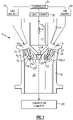
- Figure 1 illustrates an example liquid-gas mixer 10.
- the liquid-gas mixer 10 is a fuel injector incorporated into a combustor of a gas turbine engine.
- the liquid-gas mixer 10 is included in an industrial burner, or into the combustor of a rocket engine.
- the liquid-gas mixer 10 can be made of any suitable material, such as a high strength steel or a ceramic material.
- the example liquid-gas mixer 10 is provided about a mixer axis A I , and includes a central, liquid passageway 12 within a central housing 14.
- the liquid is fuel.
- the central housing 14 is connected to a mixing chamber housing 16 by way of a plurality of struts 18, and the mixing chamber housing 16 provides a mixing chamber 20 therein.
- a turbulator 22 provided radially between the central housing 14 and the mixing chamber housing 16 extends downward from the struts 18 and into the mixing chamber 20.
- the turbulator 22 includes a main body portion 24, and a plurality of first and second disturbance generators 26, 28 at a free end of the main body portion 24.
- the first and second disturbance generators 26, 28 are provided in an alternating arrangement such that adjacent first disturbance generators 26 are spaced apart by a second disturbance generator 28.
- the turbulator 22 is positioned relative to the strut 18 so as to provide two gas passageways 23, 25 on either side thereof.
- the gas is air or some other type of oxidizer.
- a first gas passageway 23 is provided radially outward (e.g., relative to the injector axis A I ) of both the liquid passageway 12 and the central housing 14, and radially inward of the turbulator 22.
- a second gas passageway 25 is provided radially outward of the turbulator 22 and radially inward of the mixing chamber housing 16.
- the first disturbance generators 26 extend from the free end of the main body portion 24 radially inward, toward the injector axis A I and into the first gas passageway 23.
- the second disturbance generators 28, on the other hand, extend from the free end of the main body portion 24 radially outward, away from the axis of the injector A I and into the second gas passageway 25.
- the first and second disturbance generators 26, 28 are curved tabs. As shown in Figure 3 , the first disturbance generators 26 are curved about respective first axes of curvature C 1 that are perpendicular to the injector axis A I . Likewise, the second disturbance generators 28 are curved about second axes of curvature C 2 that are also perpendicular to the injector axis A I .
- the disturbance generators 26, 28 do not need to be curved, however, and can instead extend from the main body portion 24 in an angled, but flat orientation. Further, the disturbance generators 26, 28 do not need to be tabs, and can be any structures provided in an alternating arrangement, including alternating conical structures.
- the liquid-gas mixer 10 is in communication with a liquid source 30, and a gas source 32.
- the liquid and gas sources 30, 32 are in turn in communication with a controller 34.
- the liquid is a fuel and the gas is air, however this application is not limited to fuel and air.
- the controller 34 can be any type of known controller, such as a computer including a processor and a computer readable medium, configured to control operation of the liquid source 30 and gas source 32 in a desired manner.
- Liquid F is provided from the liquid source 30 to the liquid passageway 12 and flows downstream to a spray tip 36.
- the spray tip 36 directs the liquid F toward the mixing chamber 20 where the liquid F mixes with gas from the gas source 32.
- the liquid source 30 is controlled with the controller 34 such that the liquid F mixes with the gas at a point directly below the turbulator 22. While a spray tip 36 is shown, this application extends to examples that do not include spray tips.
- the gas source 32 is controlled to provide gas into the first and second gas passageways 23, 25.
- the main body portion 24 of the turbulator 22 acts to bifurcate the gas from the gas source 32 into first and second gas flows A 1 , A 2 , which flow through the first and second passageways 23, 25, respectively.
- the first gas flow A 1 is disturbed by the first disturbance generators 26.
- the second disturbance generators 28 likewise disturb the second gas flow A 2 .
- the detail of this interaction between the gas flows A 1 , A 2 and the disturbance generators 26, 28 is illustrated in Figure 3 and discussed below.
- the edges E 1 and E 2 of the first disturbance generator 26 cause the first gas flow A 1 to spin into two vortexes, V 1 and V 2 , respectively.
- the vortexes V 1 and V 2 spin initially toward the middle of the ramp R created by the first disturbance generator 26, in opposite directions to one another, which leads to enhanced mixing.
- the second gas flow A 2 is spun about vortexes V 3 and V 4 by way of the edges of the second disturbance generator 28.
- the above-discussed arrangement of the first disturbance generators 26 relative to the second disturbance generators 28 leads to enhanced mixing between the liquid F and the gas flows A 1 , A 2 in the mixing chamber 20, prior to combustion. Downstream of the mixing chamber 20, the liquid-gas mixture flows to a combustion chamber 38 where the mixture is efficiently combusted and used for propulsion, for example.
- the turbulator 22 could be provided in any shape, including being generally flat, as long as the turbulator includes alternating first and second disturbance generators 26, 28 to disturb flows on either side thereof to improve mixing between a liquid and a gas.
Landscapes
- Chemical & Material Sciences (AREA)
- Engineering & Computer Science (AREA)
- Chemical Kinetics & Catalysis (AREA)
- Combustion & Propulsion (AREA)
- Mechanical Engineering (AREA)
- General Engineering & Computer Science (AREA)
- Dispersion Chemistry (AREA)
Description
- This invention was made with government support under Contract No. NNC10CA11C awarded by NASA. The Government has certain rights in this invention.
- Industrial burners and engines, such as gas turbine engines, include combustors having liquid-gas mixers, such as fuel injectors, configured to mix a liquid, such as fuel, and gas, such as air, prior to combustion, for example. Some known liquid-gas mixers are configured to disturb a flow of gas, and to spray liquid into the disturbed gas. One known type of liquid-gas mixer includes a plate with a plurality of apertures, such that gas is disturbed as it passes through the apertures in the plate. Other liquid-gas mixers include swirlers configured to swirl a gas flow about an axis of the mixer.
-
WO2012/047159 A1 discloses a mixer for injecting a liquid medium into exhaust gas with the liquid being injected into a central channel and the gas being guided by two gas passageways with a turbolator with a plurality of disturbance generators provided between the two gas passageways, as per the preamble of claim 1. -
WO2009/126487 A2 discloses a turbulator with two sets of disturbance generators on one turbolator. - Disclosed is a liquid-gas mixer according to claim 1 including a central passageway provided about an injector axis, and first and second gas passageways. The first gas passageway is radially outward of the central passageway and radially inward of the second gas passageway. A turbulator is provided between the first and second gas passageways. The turbulator includes a plurality of first disturbance generators and a plurality of second disturbance generators. The first and second disturbance generators are provided about the turbulator in an alternating arrangement.
- The turbulator includes a main body portion having a free end and an end supported by a strut, the first and second disturbance generators extending in opposite directions from the free end of the main body portion.
- The first disturbance generators extend radially inward from the free end of the main body portion into the first gas passageway.
- The second disturbance generators extend radially outward from the free end of the main body portion into the second gas passageway.
- In a further non-limiting embodiment of any of the foregoing liquid-gas mixers, adjacent ones of the first disturbance generators are spaced apart by one of the second disturbance generators.
- In a further non-limiting embodiment of any of the foregoing liquid-gas mixers, the central passageway is configured to receive a flow of liquid, and wherein the first and second gas passageways are configured to receive respective gas flows.
- In a further non-limiting embodiment of any of the foregoing liquid-gas mixers, the first and second disturbance generators are curved tabs.
- In a further non-limiting embodiment of any of the foregoing liquid-gas mixers, the first and second disturbance generators are curved about respective curvature axes, the curvature axes being perpendicular to the injector axis.
- In a further non-limiting embodiment of any of the foregoing liquid-gas mixers, the mixer includes a mixing chamber configured to collect liquid and gas, a central passageway provided about an injector axis, and a first gas passageway and a second gas passageway. The first gas passageway is radially outward of the central passageway and radially inward of the second gas passageway. Further, a turbulator is provided between the first and second gas passageways. The turbulator includes a plurality of first disturbance generators and a plurality of second disturbance generators. The first and second disturbance generators are provided about the turbulator in an alternating arrangement.
- In a further non-limiting embodiment of the foregoing mixer, the turbulator includes a main body portion having a free end and an end supported by a strut, the first and second disturbance generators extending in opposite directions from the free end of the main body portion.
- In a further non-limiting embodiment of any of the foregoing liquid-gas mixers, the liquid is fuel and wherein the gas is air.
- In a further non-limiting embodiment of any of the foregoing liquid-gas mixers, the mixer further includes a central housing defining the central passageway, a mixing chamber housing defining the mixing chamber, and a strut connecting the central housing and the mixing chamber housing, the turbulator extending from the strut.
- In a further non-limiting embodiment of any of the foregoing liquid-gas mixers, the first gas passageway is provided radially inward of the turbulator and radially outward of the central housing.
- In a further non-limiting embodiment of any of the foregoing liquid-gas mixers, the second gas passageway is provided radially outward of the turbulator and radially inward of the mixing chamber housing.
- In a further non-limiting embodiment of any of the foregoing liquid-gas mixers, adjacent first disturbance generators are spaced apart by one of the second disturbance generators.
- In a further non-limiting embodiment of any of the foregoing liquid-gas mixers, the first and second disturbance generators are curved about respective curvature axes, the curvature axes being perpendicular to the injector axis.
- Further disclosed is a method of mixing fuel and air for combustion, as per claim 9. The method includes establishing a flow of fuel through a central passageway, establishing first and second air flows through first and second air passageways, respectively, and generating a plurality of vortexes in the first and second airflows. A turbulator generates the vortexes with a plurality of first disturbance generators and a plurality of second disturbance generators. The first and second disturbance generators are provided about the turbulator in an alternating arrangement.
- In a further non-limiting embodiment of the foregoing method of mixing fuel and air for combustion, each of the first and second disturbance generators creates two oppositely-rotating vortexes.
- In a further non-limiting embodiment of either of the foregoing methods of mixing fuel and air for combustion, the method further includes spraying the fuel toward the plurality of vortexes to mix the fuel with the first and second airflows.
- In a further non-limiting embodiment of either of the foregoing methods of mixing fuel and air for combustion, the method further includes combusting the fuel-air mixture.
- These and other features of the present disclosure can be best understood from the following drawings and detailed description.
- The drawings can be briefly described as follows:
-
Figure 1 is a cross-sectional view illustrating an example liquid-gas mixer. -
Figure 2 is a perspective, cross-sectional view of the liquid-gas mixer ofFigure 1 . -
Figure 3 is a close-up view showing the detail of the disturbance generators fromFigure 1 . -
Figure 1 illustrates an example liquid-gas mixer 10. In this example, the liquid-gas mixer 10 is a fuel injector incorporated into a combustor of a gas turbine engine. In other examples, the liquid-gas mixer 10 is included in an industrial burner, or into the combustor of a rocket engine. The liquid-gas mixer 10 can be made of any suitable material, such as a high strength steel or a ceramic material. - The example liquid-
gas mixer 10 is provided about a mixer axis AI, and includes a central,liquid passageway 12 within acentral housing 14. In this example, where the liquid-gas mixer 10 is a fuel injector, the liquid is fuel. Thecentral housing 14 is connected to amixing chamber housing 16 by way of a plurality ofstruts 18, and themixing chamber housing 16 provides amixing chamber 20 therein. Aturbulator 22 provided radially between thecentral housing 14 and themixing chamber housing 16 extends downward from thestruts 18 and into themixing chamber 20. - The
turbulator 22 includes amain body portion 24, and a plurality of first andsecond disturbance generators main body portion 24. The first andsecond disturbance generators first disturbance generators 26 are spaced apart by asecond disturbance generator 28. - As best seen in
Figure 2 , theturbulator 22 is positioned relative to thestrut 18 so as to provide twogas passageways gas mixer 10 is a fuel injector, the gas is air or some other type of oxidizer. As illustrated, afirst gas passageway 23 is provided radially outward (e.g., relative to the injector axis AI) of both theliquid passageway 12 and thecentral housing 14, and radially inward of theturbulator 22. Asecond gas passageway 25 is provided radially outward of theturbulator 22 and radially inward of themixing chamber housing 16. - The
first disturbance generators 26 extend from the free end of themain body portion 24 radially inward, toward the injector axis AI and into thefirst gas passageway 23. Thesecond disturbance generators 28, on the other hand, extend from the free end of themain body portion 24 radially outward, away from the axis of the injector AI and into thesecond gas passageway 25. - In this example, the first and
second disturbance generators Figure 3 , thefirst disturbance generators 26 are curved about respective first axes of curvature C1 that are perpendicular to the injector axis AI. Likewise, thesecond disturbance generators 28 are curved about second axes of curvature C2 that are also perpendicular to the injector axis AI. Thedisturbance generators main body portion 24 in an angled, but flat orientation. Further, thedisturbance generators - With reference to
Figure 1 , the liquid-gas mixer 10 is in communication with aliquid source 30, and agas source 32. The liquid andgas sources controller 34. Again, in this example, the liquid is a fuel and the gas is air, however this application is not limited to fuel and air. Thecontroller 34 can be any type of known controller, such as a computer including a processor and a computer readable medium, configured to control operation of theliquid source 30 andgas source 32 in a desired manner. - Liquid F is provided from the
liquid source 30 to theliquid passageway 12 and flows downstream to a spray tip 36. The spray tip 36 directs the liquid F toward the mixingchamber 20 where the liquid F mixes with gas from thegas source 32. In one example, theliquid source 30 is controlled with thecontroller 34 such that the liquid F mixes with the gas at a point directly below theturbulator 22. While a spray tip 36 is shown, this application extends to examples that do not include spray tips. - The
gas source 32 is controlled to provide gas into the first andsecond gas passageways main body portion 24 of the turbulator 22 acts to bifurcate the gas from thegas source 32 into first and second gas flows A1, A2, which flow through the first andsecond passageways first disturbance generators 26. Thesecond disturbance generators 28 likewise disturb the second gas flow A2. The detail of this interaction between the gas flows A1, A2 and thedisturbance generators Figure 3 and discussed below. - Turning to
Figure 3 , the edges E1 and E2 of thefirst disturbance generator 26 cause the first gas flow A1 to spin into two vortexes, V1 and V2, respectively. As illustrated, the vortexes V1 and V2 spin initially toward the middle of the ramp R created by thefirst disturbance generator 26, in opposite directions to one another, which leads to enhanced mixing. Similarly, the second gas flow A2 is spun about vortexes V3 and V4 by way of the edges of thesecond disturbance generator 28. - The above-discussed arrangement of the
first disturbance generators 26 relative to thesecond disturbance generators 28 leads to enhanced mixing between the liquid F and the gas flows A1, A2 in the mixingchamber 20, prior to combustion. Downstream of the mixingchamber 20, the liquid-gas mixture flows to acombustion chamber 38 where the mixture is efficiently combusted and used for propulsion, for example. - It should be understood that while this application makes references to a "liquid passageway" and "gas passageways," that the fluids flowing through these passageways could be reversed (e.g., the gas could flow through the "liquid passageway" and vice versa) without compromising the mixing between the two fluids. Additionally, it is not necessary for the fuel to be liquid and the air to be gas, and in one example the above-described liquid-gas mixer can be used to effectively mix a liquid oxidizer and a gaseous fuel. Further, while reference herein has been made to "fuel" and "air," it should be understood that this application extends to other types of liquids and gasses, respectively.
- It should further be understood that, although the figures have illustrated the liquid-
gas mixer 10 as being generally cylindrical, oriented about the axis AI, theturbulator 22 could be provided in any shape, including being generally flat, as long as the turbulator includes alternating first andsecond disturbance generators - Although the different examples have the specific components shown in the illustrations, embodiments of this invention are not limited to those particular combinations. It is possible to use some of the components or features from one of the examples in combination with features or components from another one of the examples.
Claims (11)
- A liquid-gas mixer (10) comprising:a central passageway (12) provided about an injector axis;a first gas passageway (23) and a second gas passageway (25), the first gas passageway (23) radially outward of the central passageway (25) and radially inward of the second gas passageway (25); anda turbulator (22) provided between the first and second gas passageways (23, 25), the turbulator (22) including a plurality of first disturbance generators (26)characterised by the turbulator including a plurality of second disturbance generators (28), the first and second disturbance generators (26, 28) provided about the turbulator (22) in an alternating arrangement;wherein the turbulator (22) includes a main body portion having a free end and an end supported by a strut (18), the first and second disturbance generators (26, 28) extending in opposite directions from the free end of the main body portion (24);wherein the first disturbance generators (26) extend radially inward from the free end of the main body portion (24) into the first gas passageway (23); andwherein the second disturbance generators (28) extend radially outward from the free end of the main body portion (24) into the second gas passageway (25).
- The liquid-gas mixer (10) as recited in claim 1, wherein adjacent ones of the first disturbance generators (26) are spaced apart by one of the second disturbance generators (28).
- The liquid-gas mixer (10) as recited in claim 1 or 2, wherein the central passageway (12) is configured to receive a flow of liquid, and wherein the first and second gas passageways (13, 25) are configured to receive respective gas flows.
- The liquid-gas mixer (10) as recited in any preceding claim, wherein the first and second disturbance generators (26, 28) are curved tabs.
- The liquid-gas mixer (10) as recited in any preceding claim, wherein the first and second disturbance generators (26, 28) are curved about respective curvature axes (C1, C2), the curvature axes (C1, C2) being perpendicular to the injector axis.
- The liquid- gas mixer (10) of a preceding claim, further coupling a mixing chamber (20) configured to collect liquid and gas.
- The liquid-gas mixer (10) as recited in claim 6, further including:a central housing (14) defining the central passageway (12);a mixing chamber housing (16) defining the mixing chamber (20); anda strut (18) connecting the central housing (16) and the mixing chamber housing (16), the turbulator (22) extending from the strut (18).
- The liquid-gas mixer (10) as recited in claim 7, wherein the first gas passageway (23) is provided radially inward of the turbulator (22) and radially outward of the central housing (14), and optionally wherein the second gas passageway is provided radially outward of the turbulator (22) and radially inward of the mixing chamber housing (16).
- A method of mixing fuel and air for combustion, comprising:establishing a flow of fuel through a central passageway (12);establishing first and second air flows (A1, A2) through first and second air passageways (23, 25), respectively; andgenerating a plurality of vortexes (V1, V2) in the first and second airflows, wherein a turbulator (22) generates the vortexes (V1, V2) with a plurality of first disturbance generators (26) and a plurality of second disturbance generators (28), the first and second disturbance generators (26, 28) provided about the turbulator (22) in an alternating arrangement;wherein the turbulator (22) includes a main body portion having a free end and an end supported by a strut (18), the first and second disturbance generators (26, 28) extending in opposite directions from the free end of the main body portion (24);wherein the first disturbance generators (26) extend radially inward from the free end of the main body portion (24) into the first gas passageway (23); andwherein the second disturbance generators (28) extend radially outward from the free end of the main body portion (24) into the second gas passageway (25).
- The method as recited in claim 19, wherein each of the first and second disturbance generators (26, 28) creates two oppositely-rotating vortexes (V1, V2).
- The method as recited in claim 9 or 10, further including spraying the fuel toward the plurality of vortexes (V1, V2) to mix the fuel with the first and second airflows (A1, A2), and optionally further including combusting the fuel-air mixture.
Applications Claiming Priority (2)
| Application Number | Priority Date | Filing Date | Title |
|---|---|---|---|
| US13/476,386 US9764294B2 (en) | 2012-05-21 | 2012-05-21 | Liquid-gas mixer and turbulator therefor |
| PCT/US2013/039851 WO2013176876A1 (en) | 2012-05-21 | 2013-05-07 | Liquid-gas mixer and turbulator therefor |
Publications (3)
| Publication Number | Publication Date |
|---|---|
| EP2852740A1 EP2852740A1 (en) | 2015-04-01 |
| EP2852740A4 EP2852740A4 (en) | 2016-01-13 |
| EP2852740B1 true EP2852740B1 (en) | 2022-06-29 |
Family
ID=49580693
Family Applications (1)
| Application Number | Title | Priority Date | Filing Date |
|---|---|---|---|
| EP13794558.0A Active EP2852740B1 (en) | 2012-05-21 | 2013-05-07 | Liquid-gas mixer and turbulator therefor |
Country Status (3)
| Country | Link |
|---|---|
| US (1) | US9764294B2 (en) |
| EP (1) | EP2852740B1 (en) |
| WO (1) | WO2013176876A1 (en) |
Families Citing this family (1)
| Publication number | Priority date | Publication date | Assignee | Title |
|---|---|---|---|---|
| US9144774B2 (en) * | 2009-09-22 | 2015-09-29 | Turbulent Energy, Llc | Fluid mixer with internal vortex |
Family Cites Families (16)
| Publication number | Priority date | Publication date | Assignee | Title |
|---|---|---|---|---|
| US2605611A (en) | 1948-08-16 | 1952-08-05 | Solar Aircraft Co | Thrust balance structure for rotary gas engines |
| US2720754A (en) | 1950-09-29 | 1955-10-18 | Mcdonnell Aircraft Corp | Flameholder for ram jet engine |
| FR2596102B1 (en) | 1986-03-20 | 1988-05-27 | Snecma | INJECTION DEVICE WITH AXIAL CENTRIPE |
| DE3642122C1 (en) | 1986-12-10 | 1988-06-09 | Mtu Muenchen Gmbh | Fuel injector |
| IL93630A0 (en) * | 1989-03-27 | 1990-12-23 | Gen Electric | Flameholder for gas turbine engine afterburner |
| US5251447A (en) | 1992-10-01 | 1993-10-12 | General Electric Company | Air fuel mixer for gas turbine combustor |
| US5487274A (en) * | 1993-05-03 | 1996-01-30 | General Electric Company | Screech suppressor for advanced low emissions gas turbine combustor |
| US5675971A (en) | 1996-01-02 | 1997-10-14 | General Electric Company | Dual fuel mixer for gas turbine combustor |
| US5966937A (en) * | 1997-10-09 | 1999-10-19 | United Technologies Corporation | Radial inlet swirler with twisted vanes for fuel injector |
| US6820411B2 (en) | 2002-09-13 | 2004-11-23 | The Boeing Company | Compact, lightweight high-performance lift thruster incorporating swirl-augmented oxidizer/fuel injection, mixing and combustion |
| DE10340826A1 (en) | 2003-09-04 | 2005-03-31 | Rolls-Royce Deutschland Ltd & Co Kg | Homogeneous mixture formation by twisted injection of the fuel |
| US7954325B2 (en) | 2005-12-06 | 2011-06-07 | United Technologies Corporation | Gas turbine combustor |
| US8459017B2 (en) | 2008-04-09 | 2013-06-11 | Woodward, Inc. | Low pressure drop mixer for radial mixing of internal combustion engine exhaust flows, combustor incorporating same, and methods of mixing |
| EP2362148A1 (en) | 2010-02-23 | 2011-08-31 | Siemens Aktiengesellschaft | Fuel injector and swirler assembly with lobed mixer |
| US8850819B2 (en) | 2010-06-25 | 2014-10-07 | United Technologies Corporation | Swirler, fuel and air assembly and combustor |
| SE535219C2 (en) | 2010-10-06 | 2012-05-29 | Scania Cv Abp | Arrangement for introducing a liquid medium into exhaust gases from an internal combustion engine |
-
2012
- 2012-05-21 US US13/476,386 patent/US9764294B2/en not_active Expired - Fee Related
-
2013
- 2013-05-07 EP EP13794558.0A patent/EP2852740B1/en active Active
- 2013-05-07 WO PCT/US2013/039851 patent/WO2013176876A1/en not_active Ceased
Also Published As
| Publication number | Publication date |
|---|---|
| US9764294B2 (en) | 2017-09-19 |
| US20130307168A1 (en) | 2013-11-21 |
| EP2852740A1 (en) | 2015-04-01 |
| WO2013176876A1 (en) | 2013-11-28 |
| EP2852740A4 (en) | 2016-01-13 |
Similar Documents
| Publication | Publication Date | Title |
|---|---|---|
| JP6063251B2 (en) | Combustor and method for distributing fuel in the combustor | |
| JP6557463B2 (en) | Fuel injector with premixed pilot nozzle | |
| US10480791B2 (en) | Fuel injector to facilitate reduced NOx emissions in a combustor system | |
| CN102686849B (en) | For the entrance premixer of fuel-burning equipment | |
| KR102290152B1 (en) | Air fuel premixer for low emissions gas turbine combustor | |
| US9182123B2 (en) | Combustor fuel nozzle and method for supplying fuel to a combustor | |
| CN104185762B (en) | For the mixed-arrangement that fuel is mixed with oxygen-containing gas stream | |
| EP4056902B1 (en) | Fuel mixer | |
| CN105940264B (en) | combustion device | |
| EP3376109B1 (en) | Dual-fuel fuel nozzle with liquid fuel tip | |
| RU2763016C1 (en) | Combustion device of a gas turbine installation | |
| EP3278030A1 (en) | Pre-mixing based fuel nozzle for use in a combustion turbine engine | |
| EP2041494B1 (en) | Gas turbine engine premix injectors | |
| CN111630320B (en) | Burner device and multi-tube once-through boiler device | |
| CN107110505A (en) | The gas turbine unit and the method for the burner of supply gas turbine unit supplied with multithread fluid fuel | |
| US20160252254A1 (en) | Gas turbine burner hub with pilot burner | |
| US20150276225A1 (en) | Combustor wth pre-mixing fuel nozzle assembly | |
| CN102692036A (en) | Combustor with fuel nozzle liner having chevron ribs | |
| US9764294B2 (en) | Liquid-gas mixer and turbulator therefor | |
| EP2657607A2 (en) | Combustor apparatus for stoichiometric combustion | |
| US9670846B2 (en) | Enhanced mixing tube elements | |
| Brown | Liquid-Gas Mixer and Turbulator Therefor |
Legal Events
| Date | Code | Title | Description |
|---|---|---|---|
| PUAI | Public reference made under article 153(3) epc to a published international application that has entered the european phase |
Free format text: ORIGINAL CODE: 0009012 |
|
| 17P | Request for examination filed |
Effective date: 20141031 |
|
| AK | Designated contracting states |
Kind code of ref document: A1 Designated state(s): AL AT BE BG CH CY CZ DE DK EE ES FI FR GB GR HR HU IE IS IT LI LT LU LV MC MK MT NL NO PL PT RO RS SE SI SK SM TR |
|
| AX | Request for extension of the european patent |
Extension state: BA ME |
|
| DAX | Request for extension of the european patent (deleted) | ||
| RA4 | Supplementary search report drawn up and despatched (corrected) |
Effective date: 20151215 |
|
| RIC1 | Information provided on ipc code assigned before grant |
Ipc: F23D 11/38 20060101ALI20151209BHEP Ipc: B01F 15/02 20060101ALI20151209BHEP Ipc: F02C 3/14 20060101AFI20151209BHEP Ipc: B01F 3/04 20060101ALI20151209BHEP Ipc: B01F 5/00 20060101ALI20151209BHEP Ipc: F23R 3/42 20060101ALI20151209BHEP Ipc: F23D 11/10 20060101ALI20151209BHEP Ipc: F02C 7/22 20060101ALI20151209BHEP Ipc: B01F 5/06 20060101ALI20151209BHEP Ipc: F23R 3/28 20060101ALI20151209BHEP |
|
| RAP1 | Party data changed (applicant data changed or rights of an application transferred) |
Owner name: UNITED TECHNOLOGIES CORPORATION |
|
| STAA | Information on the status of an ep patent application or granted ep patent |
Free format text: STATUS: EXAMINATION IS IN PROGRESS |
|
| 17Q | First examination report despatched |
Effective date: 20191025 |
|
| RAP1 | Party data changed (applicant data changed or rights of an application transferred) |
Owner name: RAYTHEON TECHNOLOGIES CORPORATION |
|
| GRAP | Despatch of communication of intention to grant a patent |
Free format text: ORIGINAL CODE: EPIDOSNIGR1 |
|
| STAA | Information on the status of an ep patent application or granted ep patent |
Free format text: STATUS: GRANT OF PATENT IS INTENDED |
|
| RIC1 | Information provided on ipc code assigned before grant |
Ipc: B01F 25/00 20220101ALI20220111BHEP Ipc: B01F 35/71 20220101ALI20220111BHEP Ipc: B01F 25/431 20220101ALI20220111BHEP Ipc: B01F 23/213 20220101ALI20220111BHEP Ipc: F02C 7/22 20060101ALI20220111BHEP Ipc: F23R 3/28 20060101ALI20220111BHEP Ipc: F23R 3/42 20060101ALI20220111BHEP Ipc: F23D 11/38 20060101ALI20220111BHEP Ipc: F23D 11/10 20060101ALI20220111BHEP Ipc: F02C 3/14 20060101AFI20220111BHEP |
|
| INTG | Intention to grant announced |
Effective date: 20220203 |
|
| GRAS | Grant fee paid |
Free format text: ORIGINAL CODE: EPIDOSNIGR3 |
|
| GRAA | (expected) grant |
Free format text: ORIGINAL CODE: 0009210 |
|
| STAA | Information on the status of an ep patent application or granted ep patent |
Free format text: STATUS: THE PATENT HAS BEEN GRANTED |
|
| AK | Designated contracting states |
Kind code of ref document: B1 Designated state(s): AL AT BE BG CH CY CZ DE DK EE ES FI FR GB GR HR HU IE IS IT LI LT LU LV MC MK MT NL NO PL PT RO RS SE SI SK SM TR |
|
| REG | Reference to a national code |
Ref country code: GB Ref legal event code: FG4D |
|
| REG | Reference to a national code |
Ref country code: CH Ref legal event code: EP |
|
| REG | Reference to a national code |
Ref country code: DE Ref legal event code: R096 Ref document number: 602013081960 Country of ref document: DE |
|
| REG | Reference to a national code |
Ref country code: AT Ref legal event code: REF Ref document number: 1501495 Country of ref document: AT Kind code of ref document: T Effective date: 20220715 |
|
| REG | Reference to a national code |
Ref country code: IE Ref legal event code: FG4D |
|
| REG | Reference to a national code |
Ref country code: LT Ref legal event code: MG9D |
|
| PG25 | Lapsed in a contracting state [announced via postgrant information from national office to epo] |
Ref country code: SE Free format text: LAPSE BECAUSE OF FAILURE TO SUBMIT A TRANSLATION OF THE DESCRIPTION OR TO PAY THE FEE WITHIN THE PRESCRIBED TIME-LIMIT Effective date: 20220629 Ref country code: NO Free format text: LAPSE BECAUSE OF FAILURE TO SUBMIT A TRANSLATION OF THE DESCRIPTION OR TO PAY THE FEE WITHIN THE PRESCRIBED TIME-LIMIT Effective date: 20220929 Ref country code: LT Free format text: LAPSE BECAUSE OF FAILURE TO SUBMIT A TRANSLATION OF THE DESCRIPTION OR TO PAY THE FEE WITHIN THE PRESCRIBED TIME-LIMIT Effective date: 20220629 Ref country code: HR Free format text: LAPSE BECAUSE OF FAILURE TO SUBMIT A TRANSLATION OF THE DESCRIPTION OR TO PAY THE FEE WITHIN THE PRESCRIBED TIME-LIMIT Effective date: 20220629 Ref country code: GR Free format text: LAPSE BECAUSE OF FAILURE TO SUBMIT A TRANSLATION OF THE DESCRIPTION OR TO PAY THE FEE WITHIN THE PRESCRIBED TIME-LIMIT Effective date: 20220930 Ref country code: FI Free format text: LAPSE BECAUSE OF FAILURE TO SUBMIT A TRANSLATION OF THE DESCRIPTION OR TO PAY THE FEE WITHIN THE PRESCRIBED TIME-LIMIT Effective date: 20220629 Ref country code: BG Free format text: LAPSE BECAUSE OF FAILURE TO SUBMIT A TRANSLATION OF THE DESCRIPTION OR TO PAY THE FEE WITHIN THE PRESCRIBED TIME-LIMIT Effective date: 20220929 |
|
| REG | Reference to a national code |
Ref country code: NL Ref legal event code: MP Effective date: 20220629 |
|
| REG | Reference to a national code |
Ref country code: AT Ref legal event code: MK05 Ref document number: 1501495 Country of ref document: AT Kind code of ref document: T Effective date: 20220629 |
|
| PG25 | Lapsed in a contracting state [announced via postgrant information from national office to epo] |
Ref country code: RS Free format text: LAPSE BECAUSE OF FAILURE TO SUBMIT A TRANSLATION OF THE DESCRIPTION OR TO PAY THE FEE WITHIN THE PRESCRIBED TIME-LIMIT Effective date: 20220629 Ref country code: LV Free format text: LAPSE BECAUSE OF FAILURE TO SUBMIT A TRANSLATION OF THE DESCRIPTION OR TO PAY THE FEE WITHIN THE PRESCRIBED TIME-LIMIT Effective date: 20220629 |
|
| PG25 | Lapsed in a contracting state [announced via postgrant information from national office to epo] |
Ref country code: NL Free format text: LAPSE BECAUSE OF FAILURE TO SUBMIT A TRANSLATION OF THE DESCRIPTION OR TO PAY THE FEE WITHIN THE PRESCRIBED TIME-LIMIT Effective date: 20220629 |
|
| PG25 | Lapsed in a contracting state [announced via postgrant information from national office to epo] |
Ref country code: SM Free format text: LAPSE BECAUSE OF FAILURE TO SUBMIT A TRANSLATION OF THE DESCRIPTION OR TO PAY THE FEE WITHIN THE PRESCRIBED TIME-LIMIT Effective date: 20220629 Ref country code: SK Free format text: LAPSE BECAUSE OF FAILURE TO SUBMIT A TRANSLATION OF THE DESCRIPTION OR TO PAY THE FEE WITHIN THE PRESCRIBED TIME-LIMIT Effective date: 20220629 Ref country code: RO Free format text: LAPSE BECAUSE OF FAILURE TO SUBMIT A TRANSLATION OF THE DESCRIPTION OR TO PAY THE FEE WITHIN THE PRESCRIBED TIME-LIMIT Effective date: 20220629 Ref country code: PT Free format text: LAPSE BECAUSE OF FAILURE TO SUBMIT A TRANSLATION OF THE DESCRIPTION OR TO PAY THE FEE WITHIN THE PRESCRIBED TIME-LIMIT Effective date: 20221031 Ref country code: ES Free format text: LAPSE BECAUSE OF FAILURE TO SUBMIT A TRANSLATION OF THE DESCRIPTION OR TO PAY THE FEE WITHIN THE PRESCRIBED TIME-LIMIT Effective date: 20220629 Ref country code: EE Free format text: LAPSE BECAUSE OF FAILURE TO SUBMIT A TRANSLATION OF THE DESCRIPTION OR TO PAY THE FEE WITHIN THE PRESCRIBED TIME-LIMIT Effective date: 20220629 Ref country code: AT Free format text: LAPSE BECAUSE OF FAILURE TO SUBMIT A TRANSLATION OF THE DESCRIPTION OR TO PAY THE FEE WITHIN THE PRESCRIBED TIME-LIMIT Effective date: 20220629 |
|
| PG25 | Lapsed in a contracting state [announced via postgrant information from national office to epo] |
Ref country code: PL Free format text: LAPSE BECAUSE OF FAILURE TO SUBMIT A TRANSLATION OF THE DESCRIPTION OR TO PAY THE FEE WITHIN THE PRESCRIBED TIME-LIMIT Effective date: 20220629 Ref country code: IS Free format text: LAPSE BECAUSE OF FAILURE TO SUBMIT A TRANSLATION OF THE DESCRIPTION OR TO PAY THE FEE WITHIN THE PRESCRIBED TIME-LIMIT Effective date: 20221029 |
|
| REG | Reference to a national code |
Ref country code: DE Ref legal event code: R097 Ref document number: 602013081960 Country of ref document: DE |
|
| PG25 | Lapsed in a contracting state [announced via postgrant information from national office to epo] |
Ref country code: AL Free format text: LAPSE BECAUSE OF FAILURE TO SUBMIT A TRANSLATION OF THE DESCRIPTION OR TO PAY THE FEE WITHIN THE PRESCRIBED TIME-LIMIT Effective date: 20220629 |
|
| PG25 | Lapsed in a contracting state [announced via postgrant information from national office to epo] |
Ref country code: DK Free format text: LAPSE BECAUSE OF FAILURE TO SUBMIT A TRANSLATION OF THE DESCRIPTION OR TO PAY THE FEE WITHIN THE PRESCRIBED TIME-LIMIT Effective date: 20220629 Ref country code: CZ Free format text: LAPSE BECAUSE OF FAILURE TO SUBMIT A TRANSLATION OF THE DESCRIPTION OR TO PAY THE FEE WITHIN THE PRESCRIBED TIME-LIMIT Effective date: 20220629 |
|
| PLBE | No opposition filed within time limit |
Free format text: ORIGINAL CODE: 0009261 |
|
| STAA | Information on the status of an ep patent application or granted ep patent |
Free format text: STATUS: NO OPPOSITION FILED WITHIN TIME LIMIT |
|
| 26N | No opposition filed |
Effective date: 20230330 |
|
| P01 | Opt-out of the competence of the unified patent court (upc) registered |
Effective date: 20230520 |
|
| PG25 | Lapsed in a contracting state [announced via postgrant information from national office to epo] |
Ref country code: SI Free format text: LAPSE BECAUSE OF FAILURE TO SUBMIT A TRANSLATION OF THE DESCRIPTION OR TO PAY THE FEE WITHIN THE PRESCRIBED TIME-LIMIT Effective date: 20220629 |
|
| REG | Reference to a national code |
Ref country code: CH Ref legal event code: PL |
|
| PG25 | Lapsed in a contracting state [announced via postgrant information from national office to epo] |
Ref country code: MC Free format text: LAPSE BECAUSE OF FAILURE TO SUBMIT A TRANSLATION OF THE DESCRIPTION OR TO PAY THE FEE WITHIN THE PRESCRIBED TIME-LIMIT Effective date: 20220629 |
|
| REG | Reference to a national code |
Ref country code: BE Ref legal event code: MM Effective date: 20230531 |
|
| PG25 | Lapsed in a contracting state [announced via postgrant information from national office to epo] |
Ref country code: MC Free format text: LAPSE BECAUSE OF FAILURE TO SUBMIT A TRANSLATION OF THE DESCRIPTION OR TO PAY THE FEE WITHIN THE PRESCRIBED TIME-LIMIT Effective date: 20220629 Ref country code: LU Free format text: LAPSE BECAUSE OF NON-PAYMENT OF DUE FEES Effective date: 20230507 Ref country code: LI Free format text: LAPSE BECAUSE OF NON-PAYMENT OF DUE FEES Effective date: 20230531 Ref country code: IT Free format text: LAPSE BECAUSE OF FAILURE TO SUBMIT A TRANSLATION OF THE DESCRIPTION OR TO PAY THE FEE WITHIN THE PRESCRIBED TIME-LIMIT Effective date: 20220629 Ref country code: CH Free format text: LAPSE BECAUSE OF NON-PAYMENT OF DUE FEES Effective date: 20230531 |
|
| REG | Reference to a national code |
Ref country code: IE Ref legal event code: MM4A |
|
| PG25 | Lapsed in a contracting state [announced via postgrant information from national office to epo] |
Ref country code: IE Free format text: LAPSE BECAUSE OF NON-PAYMENT OF DUE FEES Effective date: 20230507 |
|
| PG25 | Lapsed in a contracting state [announced via postgrant information from national office to epo] |
Ref country code: IE Free format text: LAPSE BECAUSE OF NON-PAYMENT OF DUE FEES Effective date: 20230507 |
|
| PG25 | Lapsed in a contracting state [announced via postgrant information from national office to epo] |
Ref country code: BE Free format text: LAPSE BECAUSE OF NON-PAYMENT OF DUE FEES Effective date: 20230531 |
|
| PGFP | Annual fee paid to national office [announced via postgrant information from national office to epo] |
Ref country code: GB Payment date: 20240419 Year of fee payment: 12 |
|
| PGFP | Annual fee paid to national office [announced via postgrant information from national office to epo] |
Ref country code: DE Payment date: 20240418 Year of fee payment: 12 |
|
| PGFP | Annual fee paid to national office [announced via postgrant information from national office to epo] |
Ref country code: FR Payment date: 20240418 Year of fee payment: 12 |
|
| PG25 | Lapsed in a contracting state [announced via postgrant information from national office to epo] |
Ref country code: BG Free format text: LAPSE BECAUSE OF FAILURE TO SUBMIT A TRANSLATION OF THE DESCRIPTION OR TO PAY THE FEE WITHIN THE PRESCRIBED TIME-LIMIT Effective date: 20220629 |
|
| PG25 | Lapsed in a contracting state [announced via postgrant information from national office to epo] |
Ref country code: BG Free format text: LAPSE BECAUSE OF FAILURE TO SUBMIT A TRANSLATION OF THE DESCRIPTION OR TO PAY THE FEE WITHIN THE PRESCRIBED TIME-LIMIT Effective date: 20220629 |
|
| PG25 | Lapsed in a contracting state [announced via postgrant information from national office to epo] |
Ref country code: CY Free format text: LAPSE BECAUSE OF FAILURE TO SUBMIT A TRANSLATION OF THE DESCRIPTION OR TO PAY THE FEE WITHIN THE PRESCRIBED TIME-LIMIT; INVALID AB INITIO Effective date: 20130507 |
|
| PG25 | Lapsed in a contracting state [announced via postgrant information from national office to epo] |
Ref country code: HU Free format text: LAPSE BECAUSE OF FAILURE TO SUBMIT A TRANSLATION OF THE DESCRIPTION OR TO PAY THE FEE WITHIN THE PRESCRIBED TIME-LIMIT; INVALID AB INITIO Effective date: 20130507 |
|
| REG | Reference to a national code |
Ref country code: DE Ref legal event code: R119 Ref document number: 602013081960 Country of ref document: DE |
|
| PG25 | Lapsed in a contracting state [announced via postgrant information from national office to epo] |
Ref country code: TR Free format text: LAPSE BECAUSE OF FAILURE TO SUBMIT A TRANSLATION OF THE DESCRIPTION OR TO PAY THE FEE WITHIN THE PRESCRIBED TIME-LIMIT Effective date: 20220629 |
|
| GBPC | Gb: european patent ceased through non-payment of renewal fee |
Effective date: 20250507 |
|
| PG25 | Lapsed in a contracting state [announced via postgrant information from national office to epo] |
Ref country code: GB Free format text: LAPSE BECAUSE OF NON-PAYMENT OF DUE FEES Effective date: 20250507 |
|
| PG25 | Lapsed in a contracting state [announced via postgrant information from national office to epo] |
Ref country code: DE Free format text: LAPSE BECAUSE OF NON-PAYMENT OF DUE FEES Effective date: 20251202 |
|
| PG25 | Lapsed in a contracting state [announced via postgrant information from national office to epo] |
Ref country code: FR Free format text: LAPSE BECAUSE OF NON-PAYMENT OF DUE FEES Effective date: 20250531 |