EP2852186A1 - Method for providing a lbs network equipment with location areas of wireless communication equipments, and associated device - Google Patents
Method for providing a lbs network equipment with location areas of wireless communication equipments, and associated device Download PDFInfo
- Publication number
- EP2852186A1 EP2852186A1 EP13306301.6A EP13306301A EP2852186A1 EP 2852186 A1 EP2852186 A1 EP 2852186A1 EP 13306301 A EP13306301 A EP 13306301A EP 2852186 A1 EP2852186 A1 EP 2852186A1
- Authority
- EP
- European Patent Office
- Prior art keywords
- location
- wireless communication
- location area
- communication equipment
- current
- Prior art date
- Legal status (The legal status is an assumption and is not a legal conclusion. Google has not performed a legal analysis and makes no representation as to the accuracy of the status listed.)
- Granted
Links
- 238000004891 communication Methods 0.000 title claims abstract description 130
- 238000000034 method Methods 0.000 title claims abstract description 30
- 238000004590 computer program Methods 0.000 claims description 3
- 238000012545 processing Methods 0.000 claims description 3
- 230000006870 function Effects 0.000 description 4
- 238000010586 diagram Methods 0.000 description 3
- 230000008569 process Effects 0.000 description 3
- 230000008901 benefit Effects 0.000 description 2
- 238000013500 data storage Methods 0.000 description 2
- 230000015654 memory Effects 0.000 description 2
- 101000938567 Homo sapiens Persulfide dioxygenase ETHE1, mitochondrial Proteins 0.000 description 1
- 102100030940 Persulfide dioxygenase ETHE1, mitochondrial Human genes 0.000 description 1
- 230000005540 biological transmission Effects 0.000 description 1
- 238000012790 confirmation Methods 0.000 description 1
- 238000007418 data mining Methods 0.000 description 1
- 238000012217 deletion Methods 0.000 description 1
- 230000037430 deletion Effects 0.000 description 1
- 230000000694 effects Effects 0.000 description 1
- 230000003993 interaction Effects 0.000 description 1
- 238000004321 preservation Methods 0.000 description 1
- 230000004044 response Effects 0.000 description 1
- 230000007704 transition Effects 0.000 description 1
Images
Classifications
-
- H—ELECTRICITY
- H04—ELECTRIC COMMUNICATION TECHNIQUE
- H04W—WIRELESS COMMUNICATION NETWORKS
- H04W4/00—Services specially adapted for wireless communication networks; Facilities therefor
- H04W4/02—Services making use of location information
- H04W4/021—Services related to particular areas, e.g. point of interest [POI] services, venue services or geofences
- H04W4/022—Services related to particular areas, e.g. point of interest [POI] services, venue services or geofences with dynamic range variability
-
- H—ELECTRICITY
- H04—ELECTRIC COMMUNICATION TECHNIQUE
- H04W—WIRELESS COMMUNICATION NETWORKS
- H04W12/00—Security arrangements; Authentication; Protecting privacy or anonymity
- H04W12/02—Protecting privacy or anonymity, e.g. protecting personally identifiable information [PII]
Definitions
- the present invention relates to providing of network equipment(s) associated to location-based service(s) (or LBS) with information representative of location of wireless communication equipments.
- personalized location-based services In order to get personalized location-based services (or LBS), users of wireless communication equipments need to reveal personal information about themselves and in particular their current locations to a network equipment that is associated to the accessed LBS.
- personalized LBS offered for wireless communication equipments such as smartphones or tablets, can be targeted advertising or recommendations of purchase, contacts or events interesting the user.
- an object of this invention is to provide a location-based service that is accessed by a user wireless communication equipment with a location information ensuring the user anonymity while remaining sufficiently precise to allow this LBS to provide the user with useful personalized information.
- a method is intended for providing a network equipment associated to a location-based service with information representative of the location of a wireless communication equipment associated to at least one user identifier, and comprises a step during which one determines a location area defining an information to be provided to the network equipment and including a current location of this wireless communication equipment and current location of at least a chosen number k of other wireless communication equipments accessing this location-based service and whose each preceding location was also included into each preceding location area previously determined for this wireless communication equipment.
- the method may include additional characteristics considered separately or combined, and notably:
- a computer program product comprises a set of instructions arranged, when it is executed by processing means, for performing a method such as the one above introduced, to allow providing a network equipment associated to a location-based service with information representative of location of wireless communication equipments each associated to at least one user identifier.
- a device intended for determining information representative of location of wireless communication equipments each associated to at least one user identifier, and arranged, when it receives a location request from one of these wireless communication equipments, for determining a location area defining this information and including a current location of the requesting wireless communication equipment and current location of at least a chosen number k of other wireless communication equipments whose each preceding location was also included into each preceding location area previously determined for this requesting wireless communication equipment.
- the device may include additional characteristics considered separately or combined, and notably:
- a method intended for providing a network equipment 1 associated to a location-based service (or LBS) with information representative of locations of wireless communication equipments 2 each associated to at least one user identifier.
- LBS location-based service
- the wireless communication equipments 2 are smartphones. But this is not limited to this kind of wireless communication equipment. Indeed, it concerns any type of wireless communication equipment capable of establishing communications with other wireless communication equipments or network equipments via at least one communication network, and notably tablets, for instance.
- a communication network 3, to which wireless communication equipments 2 may be connected, is schematically illustrated in Figure 1 .
- This communication network 3 comprises a wireless communication infrastructure, allowing connection of wireless communication equipments 2 of subscribers (or users), and a wired communication infrastructure (preferably with Internet access), allowing connection of, or access to, network equipments such as servers.
- the network equipment 1 illustrated in Figure 1 is associated to at least one location-based service (or LBS). This means that it is notably in charge of providing location information, relative to registered users of wireless communication equipments 2, to at least one LBS.
- this network equipment 1 may comprise one, or each, LBS to which it is associated. In this case it provides also the personalized services offers by LBS(s) to the wireless communication equipments 2 that request them.
- Such a network equipment 1 may be a server, for instance.
- each user of a wireless communication equipment 2 that may access to a LBS is associated to one or more user identifiers (or pseudonyms) that is/are known by the network equipment 1 (here a LBS server).
- This LBS Server 1 represents a potential attacker against whom the user privacy must be protected. It offers a service in exchange for user identifier (or pseudonym) and user location information.
- the user identifiers (or pseudonyms) can be created, on behalf of the user, by a network equipment 6, connected to, or accessible via, the communication network 3 and belonging to a mobile telecommunication operator.
- This network equipment 6 may be a server intended for managing the user identifiers of each user authorized to access to the LBS server 1. So, it may perform usual operations such as creation, update and deletion. It may also communicate with the LBS server 1 to get requirements on the location accuracy, so that each location information, determined for a user and intended to be transmitted to the LBS server 1, matches these requirements.
- the LBS needs some minimum location accuracy (surface) in order to offer a relevant service that can be of interest for the user of the requesting wireless communication equipment 2.
- the method is intended for providing the network equipment 1 with information representative of locations of requesting wireless communication equipments 2.
- This method is implemented each time a wireless communication equipment 2 needs to obtain a personalized service from a LBS associated to the network equipment 1, and therefore must request this personalized service to the network equipment 1 by sending (arrow A5) a request comprising an information representative of its location with a known user identifier.
- This method comprises a step during which, each time the above mentioned need occurs, one determines a location area 7(t n ) defining the information that must be provided to the network equipment 1, at an instant t n .
- a determined location area 7(t n ) includes the current location of the requesting wireless communication equipment 2 and current location of at least a chosen number k of other wireless communication equipments 8 j accessing to the location-based service and whose each preceding location was also included into each preceding location area 7(t n-1 ) that has been previously determined at an instant t n-1 for the requesting wireless communication equipment 2.
- the surface of the determined location area 7(t n ) is larger than a chosen threshold (depending on the LBS requirements)
- This case (illustrated in figure 2C ) generally appears when other wireless communication equipments 8 j that were previously located into preceding location areas 7(t n-1 ), 7(t n-2 ) are too far from the requesting wireless communication equipment 2 at instant t n .
- This smaller location area 7(t n )' may be determined from a group of sets of current and preceding location areas 7(t n-1 ), 7(t n-2 ) sorted according to their respective surfaces and associated respectively to the user identifiers that are associated to the requesting wireless communication equipment 2.
- this group of sets the current location area 7(t 3 )' that has a surface larger than the current location area having the smallest surface, in order to provide more flexibility in future determinations using its associated user identifier.
- the determined location area defining the information to be provided to the network equipment 1, including preferably the current location of the wireless communication equipment and respective current locations of at least the chosen number k of other wireless communication equipments accessing the location-based service.
- the determined location area includes current locations of at least the chosen number k of other wireless communication equipments accessing the location-based service and whose each last location was also included into each preceding location area previously determined for the wireless communication equipment.
- the determined location area is chosen in order (i) to have a surface whose value is sufficiently large with regards to the parameters/criteria defined by the concerned LBS and/or the user, and (ii) the trajectory/Historically Smallest Co-location set (or HSCO - defined below), associated to the user identifier (or pseudonym) and including the preceding location areas and the new current location, comprises at least k elements.
- Figures 2A to 2C gives examples of location areas 7(t n ) that allows to understand more easily the disclosed method.
- the first location area 7(t 1 ) illustrated in figure 2A has been determined for the requesting wireless communication equipment 2 at an instant t 1 .
- Each circle represents a wireless communication equipment 2 or 8 j .
- the fact of being co-located with other Co(7(t 1 )) members provides anonymity to the user 2 with respect to the LBS server 1.
- This parameter k may be computed so that the HSCo contains a minimum of k other users (taking also a margin as described below) and that the surface of the location is small enough regarding the precision needed by the LBS (otherwise, another pseudonym may be created as described below). Moreover, this parameter k may be configurable by the concerned LBS and/or by the user and per LBS. Indeed, for a given user, it may also be different for each LBS (as all the LBS have not the same criticality regarding the privacy).
- the second location area 7(t 2 ) illustrated in figure 2B has been determined for the requesting wireless communication equipment 2 at an instant t 2 .
- Co(7(t 2 )) (2, 8 1 , 8 2 ).
- Co(7(t 2 )) (2, 8 1 , 8 2 ).
- This intersection of "users" in the two location areas 7(t 1 ) and 7(t 2 ) is equal to or smaller than the smallest of the co-location groups Co(7(t 1 )) and Co(7(t 2 )) taken independently.
- the Historically Smallest Co-location set (HSCo(7(t 1 ),7(t 2 )) becomes a reference set that will be used during the next determination of a location area 7(t 3 ). As this reference set becomes smaller and smaller, the surface of the next determined location area usually enlarges to maintain a required cardinality of HSCo.
- HSCo(S tn ) HSCo(S tn-1 ) ⁇ Co(7(t n )), where H tn-1 is a sequence of past location areas 7(t n-1 ), and S tn is the updated sequence of location areas including the current location area7(t n ).
- a telecommunication operator Given that a telecommunication operator has the knowledge of the locations of the wireless communication equipments of its customers (notably thanks to the base station antenna to which they are connected), it may easily compute the HSCo(S), or at least a minimum value as wireless communication equipments of customers of other telecommunication operators may be present as well in the concerned location area. This minimum value of HSCo(S) is acceptable as it allows to be sure that at least the chosen number k of wireless communication equipments (accessing the location-based service) are in the concerned location area.
- Each determination of a location area 7(t n ) may be carried out by a device 9 that may access to the current and preceding locations of the requesting wireless communication equipment 2 and to the current and preceding locations of each wireless communication equipment 8 j whose preceding location(s) was (were) included into preceding location area(s) 7(t n-1 ) previously determined for the requesting wireless communication equipment 2.
- This device 9 may equip at least one communication equipment 4 that is connected to, or accessible via, the communication network 3.
- Such a device 9 is preferably made of software modules, at least partly. But it could be also made of electronic circuit(s) or hardware modules, or a combination of hardware and software modules (in this case the device 9 comprises also a software interface allowing interworking between the hardware and software modules). In the case where it is made of software modules, it constitutes a computer program product comprising a set of instructions that can run in at least one electronic equipment comprising processing means.
- the device 9 comprises first 9 1 and second 9 2 parts (or modules) comprised respectively into first 4 and second 5 communication equipments that are connected to, or accessible via, the communication network 3.
- the respective functions of these two device parts 9 1 and 9 2 will be detailed below.
- the first communication equipment 4 may be a location server that receives the location requests (arrow A1) from the requesting wireless communication equipment 2 and returns to the latter (2) (arrow A4) a user identifier (or pseudonym) with a location area 7(t n ) that must be transmitted to the LBS server 1, so that the user's anonymity be preserved given the history of this user identifier (or pseudonym) with its associated location areas 7(t n ). So, it acts as an orchestrator for the process of choosing the user identifier (or pseudonym) and the location area surface.
- the first communication equipment 4 may communicate with the network equipment 6. More precisely, on request of its first device part 9 1 , it may trigger (arrow A2) the network equipment 6 to get the set of available user identifiers (or pseudonyms) associated to the requesting wireless communication equipments 2 and known by the LBS to be accessed.
- the response of the network equipment 6 may contain as well the location accuracy requirements of the LBS.
- the second device part 9 2 (here of the second communication equipment 5) may be in charge of storing the current and preceding locations of each requesting wireless communication equipment 2 and the current and preceding locations of each wireless communication equipment 8 j whose preceding location(s) was (were) included into preceding location area(s) 7(t n-1 ) previously determined for the requesting wireless communication equipment 2.
- the second device part 9 2 may maintain a first data structure comprising the current co-location (Co) sets for the users, and a second data structure comprising the historically shortest co-location (HSCo) sets for each user identifier (or pseudonym).
- the second part 9 2 of the device 9 (that equips the second communication equipment 5) can use data available in the infrastructure of mobile telecommunication operators with regard to the geographical deployment of base stations (or antennas), and the knowledge of the wireless communication equipments that are connected to each antenna. Then, the smallest location area for a given user may be determined by the coverage area of the antenna to which the requesting wireless communication equipment 2 is connected.
- the device part 9 1 may be also in charge of selecting the user identifier (or pseudonym) and location area in the case where more than one possibility exists. More precisely, if there are several user identifiers (or pseudonyms), each one associated with location areas 7(t n ) with different sizes and with different sets of wireless communication equipments 2 and 8 j , then the first part 9 1 of the device 9 (that equips the first communication equipment 4), compares them and selects the most appropriate user identifier (or pseudonym) and location area. The selection process takes into account several factors including the number of users who should disappear from the reference HSCo set of user identifiers (or pseudonyms) if a location area was used, and the surface of the location area compared to the requirements of the LBS.
- the first communication equipment 4 gets for each received user identifier (or pseudonym) a series of location areas with respective HSCo(S) from the second communication equipment 5 (arrow A3).
- the request of the first device part 9 1 may comprise a parameter "iteration" whose value is representative of the surface (or rank) of the location area to be selected, when the different possible location areas are sorted (for instance in an increasing order of surface). For instance, an iteration value equal to 1 may request for the smallest possible location area for the requesting wireless communication equipment 2 designated by the considered user identifier (or pseudonym).
- the first device part 9 1 does not necessarily decide to take the smallest location area computed by the second device part 9 2 even when it satisfies the current anonymity requirement with respect to the cardinality of HSCo(S). Indeed, it can select a location area with a larger surface than the smallest one to provide more flexibility in future determinations regarding the considered user identifier (or pseudonym).
- the first device part 9 1 selects a valid couple (user identifier (or pseudonym), location area), it may trigger confirmation of this selection to the second device part 9 2 (arrow A3) in order to maintain the two data structures, and may trigger transmission of this valid couple to the requesting wireless communication equipment 2 (arrow A4). Then, the requesting wireless communication equipment 2 may transmit the received valid couple to the LBS server 1 (arrow A5).
- a valid couple user identifier (or pseudonym), location area
- first 9 1 and second 9 2 parts of the device 9 could be fully comprised into the first communication equipment 4 (here a location server).
- program storage devices e.g., digital data storage media, which are machine or computer readable and encode machine- executable or computer-executable programs of instructions, wherein said instructions perform some or all of the steps of said above-described methods.
- the program storage devices may be, e.g., digital memories, magnetic storage media such as a magnetic disks and magnetic tapes, hard drives, or optically readable digital data storage media.
- the embodiments are also intended to cover computers programmed to perform said steps of the above-described methods.
- processors may be provided through the use of dedicated hardware as well as hardware capable of executing software in association with appropriate software.
- the functions may be provided by a single dedicated processor, by a single shared processor, or by a plurality of individual processors, some of which may be shared.
- explicit use of the term "processor” or “controller” should not be construed to refer exclusively to hardware capable of executing software, and may implicitly include, without limitation, digital signal processor (DSP) hardware, network processor, application specific integrated circuit (ASIC), field programmable gate array (FPGA), read only memory (ROM) for storing software, random access memory (RAM), and non volatile storage.
- DSP digital signal processor
- ASIC application specific integrated circuit
- FPGA field programmable gate array
- ROM read only memory
- RAM random access memory
- any routers shown in the figures are conceptual only. Their function may be carried out through the operation of program logic, through dedicated logic, through the interaction of program control and dedicated logic, or even manually, the particular technique being selectable by the implementer as more specifically understood from the context.
- any block diagrams herein represent conceptual views of illustrative circuitry embodying the principles of the invention.
- any flow charts, flow diagrams, state transition diagrams, pseudo code, and the like represent various processes which may be substantially represented in computer readable medium and so executed by a computer or processor, whether or not such computer or processor is explicitly shown.
Landscapes
- Engineering & Computer Science (AREA)
- Computer Networks & Wireless Communication (AREA)
- Signal Processing (AREA)
- Computer Security & Cryptography (AREA)
- Mobile Radio Communication Systems (AREA)
- Telephonic Communication Services (AREA)
Abstract
Description
- The present invention relates to providing of network equipment(s) associated to location-based service(s) (or LBS) with information representative of location of wireless communication equipments.
- In order to get personalized location-based services (or LBS), users of wireless communication equipments need to reveal personal information about themselves and in particular their current locations to a network equipment that is associated to the accessed LBS. For instance, personalized LBS offered for wireless communication equipments, such as smartphones or tablets, can be targeted advertising or recommendations of purchase, contacts or events interesting the user.
- Given that exploitation of user personal and location profiles is raising more and more concerns regarding preserving of the privacy, it has been proposed to simply associate a pseudonym to each user location instead of associating the user identifier. Such a solution allows to access anonymously to a personalized LBS, but it appears to be insufficient as a LBS can use publicly available information, such as linked-in, public telephone directory or social network, to infer the real user identifier or name of the user who is behind his pseudonym. Furthermore, as the LBS may have the history of locations of the user when he previously asked for it, this LBS can also know all the locations where the user was (including locations that can be very sensitive for the user).
- It has been also proposed to encrypt the user location to hide it when it is sent to an accessed LBS. Such a solution protects the user against intruders but not against LBS providers that are not honest or trustful entity.
- It has been also proposed to "spatially cloak" the location of the requesting user by providing an enlarged location (including other users) to the accessed LBS, so that this requesting user cannot be easily distinguished. Such a solution allows the accessed LBS to provide its service (according to the precision of the enlarged location) while still preserving the user privacy because it guarantees that k other users are present with the user in the provided enlarged location. But, over time, the set of provided enlarged locations may allow the LBS to identify the user by exploiting external publicly available information.
- So an object of this invention is to provide a location-based service that is accessed by a user wireless communication equipment with a location information ensuring the user anonymity while remaining sufficiently precise to allow this LBS to provide the user with useful personalized information.
- In a first embodiment, a method is intended for providing a network equipment associated to a location-based service with information representative of the location of a wireless communication equipment associated to at least one user identifier, and comprises a step during which one determines a location area defining an information to be provided to the network equipment and including a current location of this wireless communication equipment and current location of at least a chosen number k of other wireless communication equipments accessing this location-based service and whose each preceding location was also included into each preceding location area previously determined for this wireless communication equipment.
- The method may include additional characteristics considered separately or combined, and notably:
- when a surface of the determined location area is larger than a chosen threshold, one may determine a smaller location area defining the information to be provided to the network equipment and then one may provide the network equipment with this information associated with another user identifier also associated to the wireless communication equipment. This chosen threshold could be defined by the concerned location-based service and/or by the user per LBS in order to get the optimal benefit of the personalized service while preserving the user privacy;
- one may determine the smaller location area from a group of sets of current and preceding location areas sorted according to their respective surfaces and associated respectively to the different user identifiers that are associated to the wireless communication equipment;
- one may determine into the group a current location area having the smallest surface in order to become the smaller location area to be provided to the network equipment;
- in a variant one may determine into the group a current location area having a surface larger than a current location area having the smallest surface, in order to provide more flexibility in future determinations using its associated user identifier;
- the determined location area, defining the information to be provided to the network equipment, may include the current location of the wireless communication equipment and respective current locations of at least the chosen number k of other wireless communication equipments;
- the determined location area, defining the information to be provided to said network equipment, may include the current location of the wireless communication equipment and respective current locations of at least the chosen number k of other wireless communication equipments accessing the location-based service and whose each last location was also included into each preceding location area previously determined for the wireless communication equipment.
- In a second embodiment, a computer program product comprises a set of instructions arranged, when it is executed by processing means, for performing a method such as the one above introduced, to allow providing a network equipment associated to a location-based service with information representative of location of wireless communication equipments each associated to at least one user identifier.
- In a third embodiment, a device, intended for determining information representative of location of wireless communication equipments each associated to at least one user identifier, and arranged, when it receives a location request from one of these wireless communication equipments, for determining a location area defining this information and including a current location of the requesting wireless communication equipment and current location of at least a chosen number k of other wireless communication equipments whose each preceding location was also included into each preceding location area previously determined for this requesting wireless communication equipment.
- The device may include additional characteristics considered separately or combined, and notably:
- it may be arranged, when a surface of the determined location area is larger than a chosen threshold, for determining a smaller location area defining an information and for associating this information with another user identifier also associated to the requesting wireless communication equipment;
- it may be arranged for determining the smaller location area from a group of sets of current and preceding location areas sorted according to their respective surfaces and associated respectively to the user identifiers that are associated to the requesting wireless communication equipment;
- it may be arranged for determining into the group a current location area having the smallest surface in order to become the smaller location area;
- in a variant, it may be arranged for determining into the group a current location area having a surface larger than a current location area having the smallest surface to provide more flexibility in future determinations using its associated user identifier;
- it may be arranged for determining a location area defining the information and including the current location of the requesting wireless communication equipment and respective current locations of at least the chosen number k of other wireless communication equipments; and/or
- it may be arranged for determining a location area defining the information and including the current location of the requesting wireless communication equipment and respective current locations of at least the chosen number k of other wireless communication equipments whose each location was also included into each preceding location area previously determined for the requesting wireless communication equipment.
- Some embodiments of apparatus and/or methods in accordance with embodiments of the present invention are now described, by way of example only, and with reference to the accompagnying drawings, in which :
- The
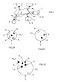
Figure 1 schematically and functionally illustrates a communication network to which are connected a wireless communication equipment and servers capable of implementing a method according to the invention, - The
Figure 2A schematically illustrates a first example of location area comprising the wireless communication equipment offigure 1 and determined for the latter at a first instant (t1), - The
Figure 2B schematically illustrates a second example of location area comprising the wireless communication equipment offigure 1 and determined for the latter at a second instant (t2), and - The
Figure 2C schematically illustrates a third example of location area comprising the wireless communication equipment offigure 1 and determined for the latter at a third instant (t3) before being rejected because it does not offer enough flexibility for the future, and a fourth example of location area including the wireless communication equipment offigure 1 and hold at the third instant (t3) instead of the third example of location area because it offers more flexibility for the future. - Hereafter is disclosed a method intended for providing a
network equipment 1 associated to a location-based service (or LBS) with information representative of locations ofwireless communication equipments 2 each associated to at least one user identifier. - In the following description it will be considered that the
wireless communication equipments 2 are smartphones. But this is not limited to this kind of wireless communication equipment. Indeed, it concerns any type of wireless communication equipment capable of establishing communications with other wireless communication equipments or network equipments via at least one communication network, and notably tablets, for instance. - A
communication network 3, to whichwireless communication equipments 2 may be connected, is schematically illustrated inFigure 1 . Thiscommunication network 3 comprises a wireless communication infrastructure, allowing connection ofwireless communication equipments 2 of subscribers (or users), and a wired communication infrastructure (preferably with Internet access), allowing connection of, or access to, network equipments such as servers. - The
network equipment 1 illustrated inFigure 1 is associated to at least one location-based service (or LBS). This means that it is notably in charge of providing location information, relative to registered users ofwireless communication equipments 2, to at least one LBS. For instance, thisnetwork equipment 1 may comprise one, or each, LBS to which it is associated. In this case it provides also the personalized services offers by LBS(s) to thewireless communication equipments 2 that request them. Such anetwork equipment 1 may be a server, for instance. - It is important to note that each user of a
wireless communication equipment 2 that may access to a LBS is associated to one or more user identifiers (or pseudonyms) that is/are known by the network equipment 1 (here a LBS server). - This LBS
Server 1 represents a potential attacker against whom the user privacy must be protected. It offers a service in exchange for user identifier (or pseudonym) and user location information. The user identifiers (or pseudonyms) can be created, on behalf of the user, by anetwork equipment 6, connected to, or accessible via, thecommunication network 3 and belonging to a mobile telecommunication operator. Thisnetwork equipment 6 may be a server intended for managing the user identifiers of each user authorized to access to theLBS server 1. So, it may perform usual operations such as creation, update and deletion. It may also communicate with theLBS server 1 to get requirements on the location accuracy, so that each location information, determined for a user and intended to be transmitted to theLBS server 1, matches these requirements. - It is also important to note that the LBS needs some minimum location accuracy (surface) in order to offer a relevant service that can be of interest for the user of the requesting
wireless communication equipment 2. - As mentioned above, the method is intended for providing the
network equipment 1 with information representative of locations of requestingwireless communication equipments 2. - This method is implemented each time a
wireless communication equipment 2 needs to obtain a personalized service from a LBS associated to thenetwork equipment 1, and therefore must request this personalized service to thenetwork equipment 1 by sending (arrow A5) a request comprising an information representative of its location with a known user identifier. - This method comprises a step during which, each time the above mentioned need occurs, one determines a location area 7(tn) defining the information that must be provided to the
network equipment 1, at an instant tn. Such a determined location area 7(tn) includes the current location of the requestingwireless communication equipment 2 and current location of at least a chosen number k of other wireless communication equipments 8j accessing to the location-based service and whose each preceding location was also included into each preceding location area 7(tn-1) that has been previously determined at an instant tn-1 for the requestingwireless communication equipment 2. - This allows to ensure that each user location information transmitted to the
LBS server 1 "hides" the user among several other users despite his previous LBS accesses. So, the privacy of the user location is protected all along his access to the LBS and not only according to one access. - Preferably, and as illustrated in
figure 2C , when the surface of the determined location area 7(tn) is larger than a chosen threshold (depending on the LBS requirements), one may determine a smaller location area 7(tn)' defining the information that must be provided to thenetwork equipment 1. Then, one may provide thenetwork equipment 1 with this last information associated with another user identifier that is also associated to the requestingwireless communication equipment 2. This case (illustrated infigure 2C ) generally appears when other wireless communication equipments 8j that were previously located into preceding location areas 7(tn-1), 7(tn-2) are too far from the requestingwireless communication equipment 2 at instant tn. - This smaller location area 7(tn)' may be determined from a group of sets of current and preceding location areas 7(tn-1), 7(tn-2) sorted according to their respective surfaces and associated respectively to the user identifiers that are associated to the requesting
wireless communication equipment 2. - For instance, one may determine into this group of sets the current location area that has the smallest surface in order to become the smaller location area that must be provided to the
LBS server 1. In a variant, illustrated infigure 2C , one may determine into this group of sets the current location area 7(t3)' that has a surface larger than the current location area having the smallest surface, in order to provide more flexibility in future determinations using its associated user identifier. - In order to increase the procured anonymity, the determined location area, defining the information to be provided to the
network equipment 1, including preferably the current location of the wireless communication equipment and respective current locations of at least the chosen number k of other wireless communication equipments accessing the location-based service. In this case, it is still more preferable that the determined location area includes current locations of at least the chosen number k of other wireless communication equipments accessing the location-based service and whose each last location was also included into each preceding location area previously determined for the wireless communication equipment. - The determined location area is chosen in order (i) to have a surface whose value is sufficiently large with regards to the parameters/criteria defined by the concerned LBS and/or the user, and (ii) the trajectory/Historically Smallest Co-location set (or HSCO - defined below), associated to the user identifier (or pseudonym) and including the preceding location areas and the new current location, comprises at least k elements.
-
Figures 2A to 2C gives examples of location areas 7(tn) that allows to understand more easily the disclosed method. - The first location area 7(t1) illustrated in
figure 2A has been determined for the requestingwireless communication equipment 2 at an instant t1. Each circle represents awireless communication equipment 2 or 8j. The requestingwireless communication equipment 2 appears here with four other wireless communication equipments 81 to 84 (j = 1 to 4). They form together a group that can be called "co-location group" and denoted Co(7(t1))=(2, 81, 82, 83, 84). The fact of being co-located with other Co(7(t1)) members provides anonymity to theuser 2 with respect to theLBS server 1. The larger is the cardinality k of the group, the higher is the procured anonymity. For instance, this cardinality k may be chosen at least equal to three (3). But it could equal to two (2) or greater than three (3). - This parameter k may be computed so that the HSCo contains a minimum of k other users (taking also a margin as described below) and that the surface of the location is small enough regarding the precision needed by the LBS (otherwise, another pseudonym may be created as described below). Moreover, this parameter k may be configurable by the concerned LBS and/or by the user and per LBS. Indeed, for a given user, it may also be different for each LBS (as all the LBS have not the same criticality regarding the privacy).
- The second location area 7(t2) illustrated in
figure 2B has been determined for the requestingwireless communication equipment 2 at an instant t2. The requestingwireless communication equipment 2 appears here with a group of two other wireless communication equipments 81 and 82 (j = 1 or 2). They form together a co-location group that can be denoted Co(7(t2))=(2, 81, 82). Here, one is not only interested in the cardinality of Co(7(t2)), which can be arbitrarily large, but also in the intersection of Co(7(t1)) and Co(7(t2)) for anonymity preservation. The result of this intersection can be called "Historically Smallest Co-location set" HSCo(7(t1),7(t2)) = {2, 81, 82}. - This intersection of "users" in the two location areas 7(t1) and 7(t2) is equal to or smaller than the smallest of the co-location groups Co(7(t1)) and Co(7(t2)) taken independently. The Historically Smallest Co-location set (HSCo(7(t1),7(t2)) becomes a reference set that will be used during the next determination of a location area 7(t3). As this reference set becomes smaller and smaller, the surface of the next determined location area usually enlarges to maintain a required cardinality of HSCo.
- When this surface becomes too large (as it is the case of the third location area 7(t3) in
figure 2C ), the user identifier (or pseudonym) can be replaced in order to allow the initialization of a new history and the selection of a smaller location area 7(t3)' allowing to form a new reference set HSCo(7(t3)') equals to Co(7(t3)') (in this case Co(7(t3)')=(2, 82, 85, 86, 87). - In a general case, the update of the HSCo set for a given user identifier (or pseudonym) can be written as follows: HSCo(Stn) = HSCo(Stn-1) ∩ Co(7(tn)), where Htn-1 is a sequence of past location areas 7(tn-1), and Stn is the updated sequence of location areas including the current location area7(tn). Given that a telecommunication operator has the knowledge of the locations of the wireless communication equipments of its customers (notably thanks to the base station antenna to which they are connected), it may easily compute the HSCo(S), or at least a minimum value as wireless communication equipments of customers of other telecommunication operators may be present as well in the concerned location area. This minimum value of HSCo(S) is acceptable as it allows to be sure that at least the chosen number k of wireless communication equipments (accessing the location-based service) are in the concerned location area.
- So, based on the knowledge of customer's locations, when a user wants to access an LBS while ensuring his privacy, a couple (user identifier, location area), ensuring that this user cannot be distinguished among others, is automatically computed.
- Each determination of a location area 7(tn) may be carried out by a device 9 that may access to the current and preceding locations of the requesting
wireless communication equipment 2 and to the current and preceding locations of each wireless communication equipment 8j whose preceding location(s) was (were) included into preceding location area(s) 7(tn-1) previously determined for the requestingwireless communication equipment 2. - This device 9 may equip at least one
communication equipment 4 that is connected to, or accessible via, thecommunication network 3. - Such a device 9 is preferably made of software modules, at least partly. But it could be also made of electronic circuit(s) or hardware modules, or a combination of hardware and software modules (in this case the device 9 comprises also a software interface allowing interworking between the hardware and software modules). In the case where it is made of software modules, it constitutes a computer program product comprising a set of instructions that can run in at least one electronic equipment comprising processing means.
- In the non-limiting example illustrated in
figure 1 , the device 9 comprises first 91 and second 92 parts (or modules) comprised respectively into first 4 and second 5 communication equipments that are connected to, or accessible via, thecommunication network 3. The respective functions of these two device parts 91 and 92 will be detailed below. - For instance, the
first communication equipment 4 may be a location server that receives the location requests (arrow A1) from the requestingwireless communication equipment 2 and returns to the latter (2) (arrow A4) a user identifier (or pseudonym) with a location area 7(tn) that must be transmitted to theLBS server 1, so that the user's anonymity be preserved given the history of this user identifier (or pseudonym) with its associated location areas 7(tn). So, it acts as an orchestrator for the process of choosing the user identifier (or pseudonym) and the location area surface. - The
first communication equipment 4 may communicate with thenetwork equipment 6. More precisely, on request of its first device part 91, it may trigger (arrow A2) thenetwork equipment 6 to get the set of available user identifiers (or pseudonyms) associated to the requestingwireless communication equipments 2 and known by the LBS to be accessed. The response of thenetwork equipment 6 may contain as well the location accuracy requirements of the LBS. - For instance, the second device part 92 (here of the second communication equipment 5) may be in charge of storing the current and preceding locations of each requesting
wireless communication equipment 2 and the current and preceding locations of each wireless communication equipment 8j whose preceding location(s) was (were) included into preceding location area(s) 7(tn-1) previously determined for the requestingwireless communication equipment 2. To this effect, the second device part 92 may maintain a first data structure comprising the current co-location (Co) sets for the users, and a second data structure comprising the historically shortest co-location (HSCo) sets for each user identifier (or pseudonym). - In order to infer a current co-location set, the second part 92 of the device 9 (that equips the second communication equipment 5) can use data available in the infrastructure of mobile telecommunication operators with regard to the geographical deployment of base stations (or antennas), and the knowledge of the wireless communication equipments that are connected to each antenna. Then, the smallest location area for a given user may be determined by the coverage area of the antenna to which the requesting
wireless communication equipment 2 is connected. - The device part 91 may be also in charge of selecting the user identifier (or pseudonym) and location area in the case where more than one possibility exists. More precisely, if there are several user identifiers (or pseudonyms), each one associated with location areas 7(tn) with different sizes and with different sets of
wireless communication equipments 2 and 8j, then the first part 91 of the device 9 (that equips the first communication equipment 4), compares them and selects the most appropriate user identifier (or pseudonym) and location area. The selection process takes into account several factors including the number of users who should disappear from the reference HSCo set of user identifiers (or pseudonyms) if a location area was used, and the surface of the location area compared to the requirements of the LBS. - On request of the first device part 91, the
first communication equipment 4 gets for each received user identifier (or pseudonym) a series of location areas with respective HSCo(S) from the second communication equipment 5 (arrow A3). The request of the first device part 91 may comprise a parameter "iteration" whose value is representative of the surface (or rank) of the location area to be selected, when the different possible location areas are sorted (for instance in an increasing order of surface). For instance, an iteration value equal to 1 may request for the smallest possible location area for the requestingwireless communication equipment 2 designated by the considered user identifier (or pseudonym). - As mentioned before, the first device part 91 does not necessarily decide to take the smallest location area computed by the second device part 92 even when it satisfies the current anonymity requirement with respect to the cardinality of HSCo(S). Indeed, it can select a location area with a larger surface than the smallest one to provide more flexibility in future determinations regarding the considered user identifier (or pseudonym).
- Finally, when the first device part 91 selects a valid couple (user identifier (or pseudonym), location area), it may trigger confirmation of this selection to the second device part 92 (arrow A3) in order to maintain the two data structures, and may trigger transmission of this valid couple to the requesting wireless communication equipment 2 (arrow A4). Then, the requesting
wireless communication equipment 2 may transmit the received valid couple to the LBS server 1 (arrow A5). - It is important to note that in a variant of embodiment the first 91 and second 92 parts of the device 9 could be fully comprised into the first communication equipment 4 (here a location server).
- The method offers several advantages:
- for the user, it allows to keep his privacy (by hiding his precise location) when he accesses over time a location-based service,
- for an operator, it allows to provide an added-value location service with privacy guarantees,
- for a location-based service, it allows to offer its services while respecting the privacy of its customer, even if data mining is performed using the location area history and publicly available information.
- A person skilled in the art would readily recognize that steps of the various above-described methods can be performed by programmed computers. Herein, some embodiments are also intended to cover program storage devices, e.g., digital data storage media, which are machine or computer readable and encode machine- executable or computer-executable programs of instructions, wherein said instructions perform some or all of the steps of said above-described methods. The program storage devices may be, e.g., digital memories, magnetic storage media such as a magnetic disks and magnetic tapes, hard drives, or optically readable digital data storage media. The embodiments are also intended to cover computers programmed to perform said steps of the above-described methods.
- The functions of the various elements shown in the figures, including any functional blocks labeled as "processors", may be provided through the use of dedicated hardware as well as hardware capable of executing software in association with appropriate software. When provided by a processor, the functions may be provided by a single dedicated processor, by a single shared processor, or by a plurality of individual processors, some of which may be shared. Moreover, explicit use of the term "processor" or "controller" should not be construed to refer exclusively to hardware capable of executing software, and may implicitly include, without limitation, digital signal processor (DSP) hardware, network processor, application specific integrated circuit (ASIC), field programmable gate array (FPGA), read only memory (ROM) for storing software, random access memory (RAM), and non volatile storage. Other hardware, conventional and/or custom, may also be included. Similarly, any routers shown in the figures are conceptual only. Their function may be carried out through the operation of program logic, through dedicated logic, through the interaction of program control and dedicated logic, or even manually, the particular technique being selectable by the implementer as more specifically understood from the context.
- It should be appreciated by those skilled in the art that any block diagrams herein represent conceptual views of illustrative circuitry embodying the principles of the invention. Similarly, it will be appreciated that any flow charts, flow diagrams, state transition diagrams, pseudo code, and the like represent various processes which may be substantially represented in computer readable medium and so executed by a computer or processor, whether or not such computer or processor is explicitly shown.
- The description and drawings merely illustrate the principles of the invention. It will thus be appreciated that those skilled in the art will be able to devise various arrangements that, although not explicitly described or shown herein, embody the principles of the invention and are included within its spirit and scope. Furthermore, all examples recited herein are principally intended expressly to be only for pedagogical purposes to aid the reader in understanding the principles of the invention and the concepts contributed by the inventor(s) to furthering the art, and are to be construed as being without limitation to such specifically recited examples and conditions. Moreover, all statements herein reciting principles, aspects, and embodiments of the invention, as well as specific examples thereof, are intended to encompass equivalents thereof.
Claims (15)
- Method for providing a network equipment (1) associated to a location-based service with information representative of location of a wireless communication equipment (2) associated to at least one user identifier, said method being characterized in that it comprises a step during which one determines a location area defining said information to be provided to said network equipment (1) and including a current location of said wireless communication equipment (2) and current location of at least a chosen number k of other wireless communication equipments (8j) accessing said location-based service and whose each preceding location was also included into each preceding location area previously determined for said wireless communication equipment (2).
- Method according to claim 1, wherein, when a surface of said determined location area is larger than a chosen threshold, one determines a smaller location area defining said information to be provided to said network equipment (1), and then one provides said network equipment (1) with said information associated with another user identifier also associated to said wireless communication equipment (2).
- Method according to claim 2, wherein one determines said smaller location area from a group of sets of current and preceding location areas sorted according to their respective surfaces and associated respectively to said user identifiers that are associated to said wireless communication equipment (2).
- Method according to claim 3, wherein one determines into said group a current location area having the smallest surface in order to become said smaller location area to be provided to said network equipment (1).
- Method according to claim 3, wherein one determines into said group a current location area having a surface larger than a current location area having the smallest surface to provide more flexibility in future determinations using its associated user identifier.
- Method according to one of claims 1 to 5, wherein said determined location area, defining said information to be provided to said network equipment (1), includes said current location of said wireless communication equipment (2) and respective current locations of at least said chosen number k of other wireless communication equipments (8j).
- Method according to claim 6, wherein said determined location area, defining said information to be provided to said network equipment (1), includes said current location of said wireless communication equipment (2) and respective current locations of at least said chosen number k of other wireless communication equipments (8j) accessing said location-based service and whose each last location was also included into each preceding location area previously determined for said wireless communication equipment (2).
- Computer program product comprising a set of instructions arranged, when it is executed by processing means, for performing the method according to one of claims 1 to 7 to allow providing a network equipment (1) associated to a location-based service with information representative of location of wireless communication equipments (2) each associated to at least one user identifier.
- Device (9) for determining information representative of location of wireless communication equipments (2) each associated to at least one user identifier, said device (9) being arranged, when it receives a location request from one of said wireless communication equipments (2), for determining a location area defining said information and including a current location of said requesting wireless communication equipment (2) and current location of at least a chosen number k of other wireless communication equipments (8j) whose each preceding location was also included into each preceding location area previously determined for said requesting wireless communication equipment (2).
- Device according to claim 9, wherein it is arranged, when a surface of said determined location area is larger than a chosen threshold, for determining a smaller location area defining said information and for associating said information with another user identifier also associated to said requesting wireless communication equipment (2).
- Device according to claim 10, wherein it is arranged for determining said smaller location area from a group of sets of current and preceding location areas sorted according to their respective surfaces and associated respectively to said user identifiers that are associated to said requesting wireless communication equipment (2).
- Device according to claim 11, wherein it is arranged for determining into said group a current location area having the smallest surface in order to become said smaller location area.
- Device according to claim 11, wherein it is arranged for determining into said group a current location area having a surface larger than a current location area having the smallest surface to provide more flexibility in future determinations using its associated user identifier.
- Device according to one of claims 9 to 13, wherein it is arranged for determining a location area defining said information and including said current location of said requesting wireless communication equipment (2) and respective current locations of at least said chosen number k of other wireless communication equipments (8j).
- Device according to claim 14, wherein it is arranged for determining a location area defining said information and including said current location of said requesting wireless communication equipment (2) and respective current locations of at least said chosen number k of other wireless communication equipments (8j) whose each last location was also included into each preceding location areas previously determined for said requesting wireless communication equipment (2).
Priority Applications (1)
| Application Number | Priority Date | Filing Date | Title |
|---|---|---|---|
| EP13306301.6A EP2852186B1 (en) | 2013-09-24 | 2013-09-24 | Method for providing a lbs network equipment with location areas of wireless communication equipments, and associated device |
Applications Claiming Priority (1)
| Application Number | Priority Date | Filing Date | Title |
|---|---|---|---|
| EP13306301.6A EP2852186B1 (en) | 2013-09-24 | 2013-09-24 | Method for providing a lbs network equipment with location areas of wireless communication equipments, and associated device |
Publications (2)
| Publication Number | Publication Date |
|---|---|
| EP2852186A1 true EP2852186A1 (en) | 2015-03-25 |
| EP2852186B1 EP2852186B1 (en) | 2018-08-01 |
Family
ID=49354603
Family Applications (1)
| Application Number | Title | Priority Date | Filing Date |
|---|---|---|---|
| EP13306301.6A Not-in-force EP2852186B1 (en) | 2013-09-24 | 2013-09-24 | Method for providing a lbs network equipment with location areas of wireless communication equipments, and associated device |
Country Status (1)
| Country | Link |
|---|---|
| EP (1) | EP2852186B1 (en) |
Cited By (2)
| Publication number | Priority date | Publication date | Assignee | Title |
|---|---|---|---|---|
| CN105516190A (en) * | 2016-01-13 | 2016-04-20 | 福建师范大学 | Position privacy protection method based on road network in continuous position service |
| CN108040321A (en) * | 2017-12-20 | 2018-05-15 | 河海大学 | The position anonymous methods of preventing playback attack under a kind of road network environment |
Citations (2)
| Publication number | Priority date | Publication date | Assignee | Title |
|---|---|---|---|---|
| US20100064373A1 (en) * | 2008-09-05 | 2010-03-11 | Iowa State University Research Foundation, Inc. | Cloaking with footprints to provide location privacy protection in location-based services |
| US20120197873A1 (en) * | 2011-01-31 | 2012-08-02 | International Business Machines Corporation | Controlling disclosure of trace data related to moving object |
-
2013
- 2013-09-24 EP EP13306301.6A patent/EP2852186B1/en not_active Not-in-force
Patent Citations (2)
| Publication number | Priority date | Publication date | Assignee | Title |
|---|---|---|---|---|
| US20100064373A1 (en) * | 2008-09-05 | 2010-03-11 | Iowa State University Research Foundation, Inc. | Cloaking with footprints to provide location privacy protection in location-based services |
| US20120197873A1 (en) * | 2011-01-31 | 2012-08-02 | International Business Machines Corporation | Controlling disclosure of trace data related to moving object |
Non-Patent Citations (2)
| Title |
|---|
| BALAJI PALANISAMY ET AL: "Location Privacy with Road Network Mix-Zones", MOBILE AD-HOC AND SENSOR NETWORKS (MSN), 2012 EIGHTH INTERNATIONAL CONFERENCE ON, IEEE, 14 December 2012 (2012-12-14), pages 124 - 131, XP032401678, ISBN: 978-1-4673-5808-8, DOI: 10.1109/MSN.2012.27 * |
| MARCO GRUTESER AND DIRK GRUNWALD: "Anonymous Usage of Location-Based Services Through Spatial andTemporal Cloaking", ACM, 2 PENN PLAZA, SUITE 701 - NEW YORK USA, 5 May 2003 (2003-05-05), XP040053835 * |
Cited By (4)
| Publication number | Priority date | Publication date | Assignee | Title |
|---|---|---|---|---|
| CN105516190A (en) * | 2016-01-13 | 2016-04-20 | 福建师范大学 | Position privacy protection method based on road network in continuous position service |
| CN105516190B (en) * | 2016-01-13 | 2018-05-04 | 福建师范大学 | Location privacy protection method based on road network in continuous position service |
| CN108040321A (en) * | 2017-12-20 | 2018-05-15 | 河海大学 | The position anonymous methods of preventing playback attack under a kind of road network environment |
| CN108040321B (en) * | 2017-12-20 | 2020-09-22 | 河海大学 | A Location Anonymous Method Against Replay Attacks in Road Network Environment |
Also Published As
| Publication number | Publication date |
|---|---|
| EP2852186B1 (en) | 2018-08-01 |
Similar Documents
| Publication | Publication Date | Title |
|---|---|---|
| US10050879B2 (en) | Techniques for selecting content based on network conditions | |
| KR102480096B1 (en) | Methods and systems for processing an ephemeral content message | |
| EP3554152B1 (en) | Categorized location identification based on historical locations of a user device | |
| US9080891B2 (en) | Methods, devices, and computer program products for exchanging interactive map information | |
| EP3095258B1 (en) | Location aware captive guest portal | |
| US10531286B2 (en) | Methods and systems for auto-completion of anonymized strings | |
| WO2014066446A1 (en) | Network access based on social-networking information | |
| US20120221716A1 (en) | Tracking Internet Usage In A Household | |
| JP2020526991A (en) | Techniques for multi-agent messaging | |
| CN106529851A (en) | Order data processing method, communication data querying method and server | |
| CN112446736A (en) | Click through rate CTR prediction method and device | |
| US20180013755A1 (en) | Logon using master password or turn-varying password | |
| EP2750418B1 (en) | Location-based service provider method and system having a user controlled location privacy mechanism | |
| EP3308496B1 (en) | System, apparatus and method for secure coordination of a rendezvous point for distributed devices using entropy multiplexing | |
| EP2852186B1 (en) | Method for providing a lbs network equipment with location areas of wireless communication equipments, and associated device | |
| CN107005864B (en) | Method, apparatus and system for changing a network based on received network information | |
| US11205194B2 (en) | Reliable user service system and method | |
| EP2884784A1 (en) | Privacy ratings for applications of mobile terminals | |
| Rivadeneira et al. | A privacy-aware framework integration into a human-in-the-loop IoT system | |
| Scipioni et al. | I’m here! privacy challenges in mobile location sharing | |
| JP2018524683A (en) | Techniques for dynamic zero-rate server clusters | |
| US8385942B1 (en) | End-user interaction framework | |
| US10447630B2 (en) | Method and system for anonymous and secure social linking during an event | |
| US20170215212A1 (en) | Dynamic generation of geographically bound manet ids | |
| WO2025224565A1 (en) | Federated recommendation systems |
Legal Events
| Date | Code | Title | Description |
|---|---|---|---|
| PUAI | Public reference made under article 153(3) epc to a published international application that has entered the european phase |
Free format text: ORIGINAL CODE: 0009012 |
|
| 17P | Request for examination filed |
Effective date: 20130924 |
|
| AK | Designated contracting states |
Kind code of ref document: A1 Designated state(s): AL AT BE BG CH CY CZ DE DK EE ES FI FR GB GR HR HU IE IS IT LI LT LU LV MC MK MT NL NO PL PT RO RS SE SI SK SM TR |
|
| AX | Request for extension of the european patent |
Extension state: BA ME |
|
| R17P | Request for examination filed (corrected) |
Effective date: 20150730 |
|
| RBV | Designated contracting states (corrected) |
Designated state(s): AL AT BE BG CH CY CZ DE DK EE ES FI FR GB GR HR HU IE IS IT LI LT LU LV MC MK MT NL NO PL PT RO RS SE SI SK SM TR |
|
| GRAP | Despatch of communication of intention to grant a patent |
Free format text: ORIGINAL CODE: EPIDOSNIGR1 |
|
| STAA | Information on the status of an ep patent application or granted ep patent |
Free format text: STATUS: GRANT OF PATENT IS INTENDED |
|
| RIC1 | Information provided on ipc code assigned before grant |
Ipc: H04W 4/02 20180101AFI20180208BHEP Ipc: H04W 12/02 20090101ALI20180208BHEP Ipc: H04W 4/021 20180101ALI20180208BHEP |
|
| INTG | Intention to grant announced |
Effective date: 20180222 |
|
| RAP1 | Party data changed (applicant data changed or rights of an application transferred) |
Owner name: ALCATEL LUCENT |
|
| GRAS | Grant fee paid |
Free format text: ORIGINAL CODE: EPIDOSNIGR3 |
|
| GRAA | (expected) grant |
Free format text: ORIGINAL CODE: 0009210 |
|
| STAA | Information on the status of an ep patent application or granted ep patent |
Free format text: STATUS: THE PATENT HAS BEEN GRANTED |
|
| AK | Designated contracting states |
Kind code of ref document: B1 Designated state(s): AL AT BE BG CH CY CZ DE DK EE ES FI FR GB GR HR HU IE IS IT LI LT LU LV MC MK MT NL NO PL PT RO RS SE SI SK SM TR |
|
| REG | Reference to a national code |
Ref country code: GB Ref legal event code: FG4D |
|
| REG | Reference to a national code |
Ref country code: CH Ref legal event code: EP Ref country code: AT Ref legal event code: REF Ref document number: 1025780 Country of ref document: AT Kind code of ref document: T Effective date: 20180815 |
|
| REG | Reference to a national code |
Ref country code: IE Ref legal event code: FG4D |
|
| REG | Reference to a national code |
Ref country code: DE Ref legal event code: R096 Ref document number: 602013041110 Country of ref document: DE |
|
| REG | Reference to a national code |
Ref country code: DE Ref legal event code: R082 Ref document number: 602013041110 Country of ref document: DE Representative=s name: BOETERS & LIECK, DE Ref country code: DE Ref legal event code: R081 Ref document number: 602013041110 Country of ref document: DE Owner name: PROVENANCE ASSET GROUP LLC, ESSEX, US Free format text: FORMER OWNER: ALCATEL LUCENT, NOZAY, FR |
|
| REG | Reference to a national code |
Ref country code: NL Ref legal event code: MP Effective date: 20180801 |
|
| REG | Reference to a national code |
Ref country code: LT Ref legal event code: MG4D |
|
| RAP2 | Party data changed (patent owner data changed or rights of a patent transferred) |
Owner name: PROVENANCE ASSET GROUP LLC |
|
| REG | Reference to a national code |
Ref country code: AT Ref legal event code: MK05 Ref document number: 1025780 Country of ref document: AT Kind code of ref document: T Effective date: 20180801 |
|
| PG25 | Lapsed in a contracting state [announced via postgrant information from national office to epo] |
Ref country code: BG Free format text: LAPSE BECAUSE OF FAILURE TO SUBMIT A TRANSLATION OF THE DESCRIPTION OR TO PAY THE FEE WITHIN THE PRESCRIBED TIME-LIMIT Effective date: 20181101 Ref country code: GR Free format text: LAPSE BECAUSE OF FAILURE TO SUBMIT A TRANSLATION OF THE DESCRIPTION OR TO PAY THE FEE WITHIN THE PRESCRIBED TIME-LIMIT Effective date: 20181102 Ref country code: NO Free format text: LAPSE BECAUSE OF FAILURE TO SUBMIT A TRANSLATION OF THE DESCRIPTION OR TO PAY THE FEE WITHIN THE PRESCRIBED TIME-LIMIT Effective date: 20181101 Ref country code: SE Free format text: LAPSE BECAUSE OF FAILURE TO SUBMIT A TRANSLATION OF THE DESCRIPTION OR TO PAY THE FEE WITHIN THE PRESCRIBED TIME-LIMIT Effective date: 20180801 Ref country code: IS Free format text: LAPSE BECAUSE OF FAILURE TO SUBMIT A TRANSLATION OF THE DESCRIPTION OR TO PAY THE FEE WITHIN THE PRESCRIBED TIME-LIMIT Effective date: 20181201 Ref country code: AT Free format text: LAPSE BECAUSE OF FAILURE TO SUBMIT A TRANSLATION OF THE DESCRIPTION OR TO PAY THE FEE WITHIN THE PRESCRIBED TIME-LIMIT Effective date: 20180801 Ref country code: PL Free format text: LAPSE BECAUSE OF FAILURE TO SUBMIT A TRANSLATION OF THE DESCRIPTION OR TO PAY THE FEE WITHIN THE PRESCRIBED TIME-LIMIT Effective date: 20180801 Ref country code: NL Free format text: LAPSE BECAUSE OF FAILURE TO SUBMIT A TRANSLATION OF THE DESCRIPTION OR TO PAY THE FEE WITHIN THE PRESCRIBED TIME-LIMIT Effective date: 20180801 Ref country code: LT Free format text: LAPSE BECAUSE OF FAILURE TO SUBMIT A TRANSLATION OF THE DESCRIPTION OR TO PAY THE FEE WITHIN THE PRESCRIBED TIME-LIMIT Effective date: 20180801 Ref country code: RS Free format text: LAPSE BECAUSE OF FAILURE TO SUBMIT A TRANSLATION OF THE DESCRIPTION OR TO PAY THE FEE WITHIN THE PRESCRIBED TIME-LIMIT Effective date: 20180801 Ref country code: FI Free format text: LAPSE BECAUSE OF FAILURE TO SUBMIT A TRANSLATION OF THE DESCRIPTION OR TO PAY THE FEE WITHIN THE PRESCRIBED TIME-LIMIT Effective date: 20180801 |
|
| REG | Reference to a national code |
Ref country code: CH Ref legal event code: PK Free format text: BERICHTIGUNGEN |
|
| RIC2 | Information provided on ipc code assigned after grant |
Ipc: H04W 12/02 20090101ALI20180208BHEP Ipc: H04W 4/02 20180101AFI20180208BHEP Ipc: H04W 4/021 20180101ALI20180208BHEP |
|
| REG | Reference to a national code |
Ref country code: GB Ref legal event code: 732E Free format text: REGISTERED BETWEEN 20190131 AND 20190206 |
|
| PG25 | Lapsed in a contracting state [announced via postgrant information from national office to epo] |
Ref country code: HR Free format text: LAPSE BECAUSE OF FAILURE TO SUBMIT A TRANSLATION OF THE DESCRIPTION OR TO PAY THE FEE WITHIN THE PRESCRIBED TIME-LIMIT Effective date: 20180801 Ref country code: AL Free format text: LAPSE BECAUSE OF FAILURE TO SUBMIT A TRANSLATION OF THE DESCRIPTION OR TO PAY THE FEE WITHIN THE PRESCRIBED TIME-LIMIT Effective date: 20180801 Ref country code: LV Free format text: LAPSE BECAUSE OF FAILURE TO SUBMIT A TRANSLATION OF THE DESCRIPTION OR TO PAY THE FEE WITHIN THE PRESCRIBED TIME-LIMIT Effective date: 20180801 |
|
| PG25 | Lapsed in a contracting state [announced via postgrant information from national office to epo] |
Ref country code: RO Free format text: LAPSE BECAUSE OF FAILURE TO SUBMIT A TRANSLATION OF THE DESCRIPTION OR TO PAY THE FEE WITHIN THE PRESCRIBED TIME-LIMIT Effective date: 20180801 Ref country code: EE Free format text: LAPSE BECAUSE OF FAILURE TO SUBMIT A TRANSLATION OF THE DESCRIPTION OR TO PAY THE FEE WITHIN THE PRESCRIBED TIME-LIMIT Effective date: 20180801 Ref country code: IT Free format text: LAPSE BECAUSE OF FAILURE TO SUBMIT A TRANSLATION OF THE DESCRIPTION OR TO PAY THE FEE WITHIN THE PRESCRIBED TIME-LIMIT Effective date: 20180801 Ref country code: MC Free format text: LAPSE BECAUSE OF FAILURE TO SUBMIT A TRANSLATION OF THE DESCRIPTION OR TO PAY THE FEE WITHIN THE PRESCRIBED TIME-LIMIT Effective date: 20180801 Ref country code: ES Free format text: LAPSE BECAUSE OF FAILURE TO SUBMIT A TRANSLATION OF THE DESCRIPTION OR TO PAY THE FEE WITHIN THE PRESCRIBED TIME-LIMIT Effective date: 20180801 Ref country code: CZ Free format text: LAPSE BECAUSE OF FAILURE TO SUBMIT A TRANSLATION OF THE DESCRIPTION OR TO PAY THE FEE WITHIN THE PRESCRIBED TIME-LIMIT Effective date: 20180801 |
|
| REG | Reference to a national code |
Ref country code: CH Ref legal event code: PL |
|
| REG | Reference to a national code |
Ref country code: DE Ref legal event code: R097 Ref document number: 602013041110 Country of ref document: DE |
|
| PG25 | Lapsed in a contracting state [announced via postgrant information from national office to epo] |
Ref country code: SK Free format text: LAPSE BECAUSE OF FAILURE TO SUBMIT A TRANSLATION OF THE DESCRIPTION OR TO PAY THE FEE WITHIN THE PRESCRIBED TIME-LIMIT Effective date: 20180801 Ref country code: DK Free format text: LAPSE BECAUSE OF FAILURE TO SUBMIT A TRANSLATION OF THE DESCRIPTION OR TO PAY THE FEE WITHIN THE PRESCRIBED TIME-LIMIT Effective date: 20180801 Ref country code: SM Free format text: LAPSE BECAUSE OF FAILURE TO SUBMIT A TRANSLATION OF THE DESCRIPTION OR TO PAY THE FEE WITHIN THE PRESCRIBED TIME-LIMIT Effective date: 20180801 |
|
| PLBE | No opposition filed within time limit |
Free format text: ORIGINAL CODE: 0009261 |
|
| STAA | Information on the status of an ep patent application or granted ep patent |
Free format text: STATUS: NO OPPOSITION FILED WITHIN TIME LIMIT |
|
| REG | Reference to a national code |
Ref country code: BE Ref legal event code: MM Effective date: 20180930 |
|
| REG | Reference to a national code |
Ref country code: IE Ref legal event code: MM4A |
|
| PG25 | Lapsed in a contracting state [announced via postgrant information from national office to epo] |
Ref country code: LU Free format text: LAPSE BECAUSE OF NON-PAYMENT OF DUE FEES Effective date: 20180924 |
|
| 26N | No opposition filed |
Effective date: 20190503 |
|
| PG25 | Lapsed in a contracting state [announced via postgrant information from national office to epo] |
Ref country code: IE Free format text: LAPSE BECAUSE OF NON-PAYMENT OF DUE FEES Effective date: 20180924 |
|
| PG25 | Lapsed in a contracting state [announced via postgrant information from national office to epo] |
Ref country code: CH Free format text: LAPSE BECAUSE OF NON-PAYMENT OF DUE FEES Effective date: 20180930 Ref country code: LI Free format text: LAPSE BECAUSE OF NON-PAYMENT OF DUE FEES Effective date: 20180930 Ref country code: FR Free format text: LAPSE BECAUSE OF NON-PAYMENT OF DUE FEES Effective date: 20181001 Ref country code: BE Free format text: LAPSE BECAUSE OF NON-PAYMENT OF DUE FEES Effective date: 20180930 Ref country code: SI Free format text: LAPSE BECAUSE OF FAILURE TO SUBMIT A TRANSLATION OF THE DESCRIPTION OR TO PAY THE FEE WITHIN THE PRESCRIBED TIME-LIMIT Effective date: 20180801 |
|
| PG25 | Lapsed in a contracting state [announced via postgrant information from national office to epo] |
Ref country code: MT Free format text: LAPSE BECAUSE OF NON-PAYMENT OF DUE FEES Effective date: 20180924 |
|
| PG25 | Lapsed in a contracting state [announced via postgrant information from national office to epo] |
Ref country code: TR Free format text: LAPSE BECAUSE OF FAILURE TO SUBMIT A TRANSLATION OF THE DESCRIPTION OR TO PAY THE FEE WITHIN THE PRESCRIBED TIME-LIMIT Effective date: 20180801 |
|
| PG25 | Lapsed in a contracting state [announced via postgrant information from national office to epo] |
Ref country code: PT Free format text: LAPSE BECAUSE OF FAILURE TO SUBMIT A TRANSLATION OF THE DESCRIPTION OR TO PAY THE FEE WITHIN THE PRESCRIBED TIME-LIMIT Effective date: 20180801 Ref country code: HU Free format text: LAPSE BECAUSE OF FAILURE TO SUBMIT A TRANSLATION OF THE DESCRIPTION OR TO PAY THE FEE WITHIN THE PRESCRIBED TIME-LIMIT; INVALID AB INITIO Effective date: 20130924 |
|
| PG25 | Lapsed in a contracting state [announced via postgrant information from national office to epo] |
Ref country code: CY Free format text: LAPSE BECAUSE OF FAILURE TO SUBMIT A TRANSLATION OF THE DESCRIPTION OR TO PAY THE FEE WITHIN THE PRESCRIBED TIME-LIMIT Effective date: 20180801 Ref country code: MK Free format text: LAPSE BECAUSE OF NON-PAYMENT OF DUE FEES Effective date: 20180801 |
|
| PGFP | Annual fee paid to national office [announced via postgrant information from national office to epo] |
Ref country code: GB Payment date: 20200909 Year of fee payment: 8 |
|
| PGFP | Annual fee paid to national office [announced via postgrant information from national office to epo] |
Ref country code: DE Payment date: 20201001 Year of fee payment: 8 |
|
| REG | Reference to a national code |
Ref country code: DE Ref legal event code: R119 Ref document number: 602013041110 Country of ref document: DE |
|
| GBPC | Gb: european patent ceased through non-payment of renewal fee |
Effective date: 20210924 |
|
| PG25 | Lapsed in a contracting state [announced via postgrant information from national office to epo] |
Ref country code: GB Free format text: LAPSE BECAUSE OF NON-PAYMENT OF DUE FEES Effective date: 20210924 Ref country code: DE Free format text: LAPSE BECAUSE OF NON-PAYMENT OF DUE FEES Effective date: 20220401 |