EP2852043A1 - Improvements in or relating to power modules for use in power transmission networks - Google Patents
Improvements in or relating to power modules for use in power transmission networks Download PDFInfo
- Publication number
- EP2852043A1 EP2852043A1 EP13185595.9A EP13185595A EP2852043A1 EP 2852043 A1 EP2852043 A1 EP 2852043A1 EP 13185595 A EP13185595 A EP 13185595A EP 2852043 A1 EP2852043 A1 EP 2852043A1
- Authority
- EP
- European Patent Office
- Prior art keywords
- connection
- module
- power module
- configurable power
- energy storage
- Prior art date
- Legal status (The legal status is an assumption and is not a legal conclusion. Google has not performed a legal analysis and makes no representation as to the accuracy of the status listed.)
- Withdrawn
Links
Images






Classifications
-
- H—ELECTRICITY
- H02—GENERATION; CONVERSION OR DISTRIBUTION OF ELECTRIC POWER
- H02M—APPARATUS FOR CONVERSION BETWEEN AC AND AC, BETWEEN AC AND DC, OR BETWEEN DC AND DC, AND FOR USE WITH MAINS OR SIMILAR POWER SUPPLY SYSTEMS; CONVERSION OF DC OR AC INPUT POWER INTO SURGE OUTPUT POWER; CONTROL OR REGULATION THEREOF
- H02M7/00—Conversion of AC power input into DC power output; Conversion of DC power input into AC power output
- H02M7/42—Conversion of DC power input into AC power output without possibility of reversal
- H02M7/44—Conversion of DC power input into AC power output without possibility of reversal by static converters
- H02M7/48—Conversion of DC power input into AC power output without possibility of reversal by static converters using discharge tubes with control electrode or semiconductor devices with control electrode
- H02M7/483—Converters with outputs that each can have more than two voltages levels
-
- H—ELECTRICITY
- H02—GENERATION; CONVERSION OR DISTRIBUTION OF ELECTRIC POWER
- H02M—APPARATUS FOR CONVERSION BETWEEN AC AND AC, BETWEEN AC AND DC, OR BETWEEN DC AND DC, AND FOR USE WITH MAINS OR SIMILAR POWER SUPPLY SYSTEMS; CONVERSION OF DC OR AC INPUT POWER INTO SURGE OUTPUT POWER; CONTROL OR REGULATION THEREOF
- H02M7/00—Conversion of AC power input into DC power output; Conversion of DC power input into AC power output
- H02M7/42—Conversion of DC power input into AC power output without possibility of reversal
- H02M7/44—Conversion of DC power input into AC power output without possibility of reversal by static converters
- H02M7/48—Conversion of DC power input into AC power output without possibility of reversal by static converters using discharge tubes with control electrode or semiconductor devices with control electrode
- H02M7/483—Converters with outputs that each can have more than two voltages levels
- H02M7/4835—Converters with outputs that each can have more than two voltages levels comprising two or more cells, each including a switchable capacitor, the capacitors having a nominal charge voltage which corresponds to a given fraction of the input voltage, and the capacitors being selectively connected in series to determine the instantaneous output voltage
Definitions
- This invention relates to a configurable power module for use in a power transmission network, and more particularly for use in a high voltage direct current (HVDC) power transmission network, and to each of a voltage source converter and a direct current circuit breaker apparatus including such a module, as well as methods of configuring such a module.
- HVDC high voltage direct current
- a configurable power module for use in a power transmission network, comprising:
- connection module which is operable to interconnect first and second sub-modules in a first connection mode in which a parallel connection is established between first and second energy storage devices of corresponding sub-modules helps to reduce conduction losses within the configurable power module as a whole because current flow can be shared within the parallel connection during, e.g. normal operation of the configurable power module.
- connection module which is additionally operable to interconnect the first and second sub-modules in a second connection mode in which the energy storage devices are able to combine and generate a blocking voltage to oppose the flow of current, e.g. a fault current, provides the configurable power module with further useful functionality and so helps to render it more cost effective than, e.g. conventional power modules.
- connection module in the first connection mode establishes a parallel connection between the first and second energy storage devices which allows current to flow within the parallel connection in first and second opposite directions.
- Allowing current to flow within the parallel connection in first and second opposite directions permits the configurable power module to selectively provide a positive voltage source or a negative voltage source (as well as zero voltage) which can be used, for example, respectively to increase or decrease an output voltage at an alternating current (AC) terminal of a voltage source converter.
- AC alternating current
- connection module includes:
- first and second limbs readily facilitates a parallel connection between the first and second sub-modules, while the inclusion of a bi-directional current flow control element in each limb provides a desired degree of control over the manner in which current flows through the connection module and in turn the first and second energy storage devices, such that fault current blocking in at least one first direction is possible.
- the first connection module portion further includes a first unidirectional current flow control element which permits current to flow therethrough in only one direction, the first unidirectional current flow control element interconnecting the first and second limbs to selectively establish a first series connection between the first and second energy storage devices and permit current to flow through the connection module in the first direction when each of the first pair of bi-directional current flow control elements is blocking current flow in the first direction.
- a first unidirectional current flow control element which permits current to flow therethrough in only one direction
- the first unidirectional current flow control element interconnecting the first and second limbs to selectively establish a first series connection between the first and second energy storage devices and permit current to flow through the connection module in the first direction when each of the first pair of bi-directional current flow control elements is blocking current flow in the first direction.
- connection module portion with a first unidirectional current flow control element increases the current flow path options through the connection module and facilitates fault current blocking in a second direction.
- connection module may include a plurality of first connection module portions, and adjacent pairs of the first connection module portions may be separated by a further energy storage device connected in parallel between the first and second limbs.
- connection module additionally includes a second connection module portion including a second pair of bi-directional current flow control elements one of which lies within the first limb and the other of which lies within the second limb, each of the second pair of bi-directional current flow control elements selectively blocking current flow through the corresponding limb in the same second direction opposite the first direction in which each of the first pair of bi-directional current flow control elements of the first connection module portion selectively blocks current flow, the second module portion further including a second unidirectional current flow control element which interconnects the first and second limbs to establish a second series connection between the first and second energy storage devices and permits current to flow through the connection module in the second direction when each of the second pair of bi-directional current flow control elements is blocking current flow in the second direction, the second connection module portion lying next to the first connection portion to define a bi-directional module portion.
- connection module portion allows the configurable power module of the invention to make use of a greater possible blocking voltage, e.g. as provided for by the inclusion in the power module of a larger number of energy storage devices, to oppose a fault current flowing in each of first and second directions.
- connection module includes a plurality of first and second connection module portions lying next to one another to define respective bi-directional module portions, adjacent pairs of bi-directional module portions being separated by a further energy storage device connected in parallel between the first and second limbs.
- the configurable power module further includes a control unit arranged in operative communication with each of the first and second sub-modules and the connection module, the control unit in use configuring the configurable power module to operate in a normal mode and in a fault blocking mode, the control unit when configuring the configurable power module to operate in the normal mode operating the connection module in the first connection mode in which the parallel-connected energy storage devices combine with one another to form a larger combined energy store, and the control unit further switching on and off respective switching elements in the first and second modules to selectively direct current through the combined energy store such that the configurable power module is able to provide a voltage source commensurate in size with the larger size of the combined energy store, and the control unit when configuring the configurable power module to operate in the fault blocking mode switching off all of the switching elements in the first and second sub-modules and operating the connection module in the second connection mode.
- a control unit arranged in operative communication with each of the first and second sub-modules and the connection module, the control unit in use configuring the configura
- control unit provides the configurable power module with a first degree of desired functionality useful in voltage source converters.
- a voltage source converter comprising at least one converter limb which includes first and second limb portions each of which includes at least one configurable power module as described hereinabove and at least one half-bridge module.
- Such a voltage source converter is able to utilise the lower capital cost and lower switching losses associated with the or each conventional half-bridge module while at the same time allowing the voltage source converter to block a fault current in a second direction in which half-bridge modules ordinarily are unable to block.
- the configurable power module may further include a control unit arranged in operative communication with each of the first and second sub-modules and the connection module, the control unit in use configuring the configurable power module to operate in a normal mode and in a fault blocking mode, the control unit when configuring the configurable power module to operate in the normal mode switching off all of the switching elements in the first and second sub-modules and operating the bi-directional current flow control elements in the connection module to block current flow between the first and second connection terminals, and the control unit when configuring the configurable power module to operate in the fault blocking mode carrying out the following operations in the following order:
- control unit in use configures the configurable power module to operate in a first fault blocking mode to block a fault current flowing in the first direction between the first and second connection terminals, the control unit when so configuring the configurable power module carrying out the following operations in the following order:
- the control unit may in use additionally configure the configurable power module to operate in a second fault blocking mode to block a fault current flowing in the second direction between the first and second connection terminals, the control unit when so configuring the configurable power module carrying out the following operations in the following order:
- control unit provides the configurable power module with various a second degrees of desired functionality useful in direct current circuit breaker apparatuses.
- control unit when operating the connection module in its second connection mode operates the connection module to interconnect the plurality of energy storage devices in series with one another.
- Interconnecting the plurality of energy storage devices in series with one another leads to a summing of the energy stored by each one such that when combined they are able together to generate a blocking voltage which is greater than that which each alone could generate, and so when combined in such a way the configurable power module is able to oppose a larger fault current.
- control unit when operating the connection module in its second connection mode progressively interconnects respective ones of the plurality of energy storage devices.
- Such progressive interconnecting of respective ones of the plurality of energy storage devices allows the configurable power module to modify, i.e. sculpt, the shape of a fault current waveform, e.g. so as to give a low rate of change of current as the fault current is extinguished.
- sculpting of the fault current waveform means that extinguishing the fault current can be achieved at a point when the energy storage in the various energy storage devices within the configurable power module is minimised so as to minimise also any corresponding over voltage.
- each energy storage device includes a surge arrester connected in parallel therewith.
- a direct current circuit breaker apparatus comprising main and ancillary current paths, the main current path including an electronic switch and a mechanical circuit breaker arranged in series with one another, and the ancillary current path including a configurable power module as described hereinabove.
- the configurable power module within such a circuit breaker apparatus presents a high impedance during operation in its normal mode, and when configured to operate in its fault blocking mode is able initially to present a low impedance to a fault current, then control the rate of change of voltage as contacts in the mechanical circuit breaker begin to part, before controlling transient over voltage once the said contacts are open.
- Such a method provides the configurable power module with a first degree of desired functionality useful in voltage source converters.
- Such a method provides the configurable power module with a second degree of desired functionality which is useful in direct current circuit breaker apparatuses.
- a configurable power module according to a first embodiment of the invention is designated generally by reference numeral 10.
- the first configurable power module 10 includes first and second sub-modules 12, 14 which are interconnected by a connection module 16 that is operable to interconnect the first and second sub-modules 12, 14 in first and second connection modes.
- the first sub-module 12 has a first pair 18 of first and second switching elements 20, 22 which are separated by a first connection terminal 24, and which are connected in parallel with a first energy storage device 26.
- each of the switching elements 20, 22 is a bi-directional current flow control element 28 which selectively blocks current flow therethrough in one direction while always permitting current to flow in another, opposite direction.
- each bi-directional current flow control element 28 includes a semiconductor device 30 in the form of, e.g. an Insulated Gate Bipolar Transistor (IGBT), which is connected in parallel with an anti-parallel diode 32. It is, however, possible to use another semiconductor device 30 instead of an IGBT.
- IGBT Insulated Gate Bipolar Transistor
- the first energy storage device 26 is a first capacitor 34, although other forms of energy storage device are also possible.
- the second sub-module 14 has a second pair 36 of third and fourth switching elements 38, 40 which are separated by a second connection terminal 42, and which are connected in parallel with a second energy storage device 44.
- Each of the third and fourth switching elements 38, 40 is a bi-directional current flow control element 28 of the type described immediately above, and the second energy storage device 44 is a second capacitor 46, although other forms of energy storage device are again also possible.
- the connection module 16 includes a first limb 48 which extends between a first side 50 of each of the first and second energy storage devices 26, 44, i.e. the first and second capacitors 34, 46.
- the connection module 16 also includes a second limb 52 which extends between a second side 54 of each of the first and second capacitors 34, 46.
- each of the first and second capacitors 34, 46 is arranged so that its respective first side 50 is the positive side thereof.
- connection module 16 includes a first connection module portion 56 which includes a first pair 58 of first and second further bi-directional current flow control elements 60, 62.
- the first further bi-directional current flow control element 60 lies within the first limb 48 while the second lies within the second limb 52.
- each of the further bi-directional current flow control elements 60, 62 is similar to the bi-directional current flow control elements 28 which form the first, second, third and fourth switching elements 20, 22, 38, 40 described above, and to that end each further bi-directional current flow control element 60, 62 selectively blocks current flow through its given limb 48, 52 in one direction while always permitting current to flow through the same limb 48, 52 in another, opposite direction. More particularly each of the further bi-directional current flow control elements 60, 62 is arranged so that they both selectively block current flow through the corresponding limb 48, 52 in the same first direction D 1 , while always allowing current flow through the given limb 48, 52 in the same second direction D 2 which is opposite the first direction D 1 . Other types of further bi-directional current flow control elements 60, 62 are also possible.
- the first connection module portion 56 also includes a first unidirectional current flow control element 64 which permits current flow therethrough in only one direction.
- the first unidirectional current flow control element 64 is a first diode 66.
- the first diode 66 interconnects the first and second limbs 48, 52 and, more particularly, establishes a current flow path from the second side 54 of the second capacitor 46 to the first side 50 of the first capacitor 34 so as to selectively establish a first series connection between the first and second capacitors 34, 46 which permits current to flow through the connection module 16 in the first direction D 1 when each of the first pair 58 of further bi-directional current flow control elements 60, 62 is otherwise blocking current flow in the first direction D 1 .
- the first configurable power module 10 also includes a first control unit 68 which is arranged in operative communication with each of the first and second sub-modules 12, 14 and the connection module 16.
- the first control unit 68 configures the first configurable power module 10 to operate in a normal mode and in a fault blocking mode.
- the first control unit 68 When configuring the first configurable power module 10 to operate in the normal mode the first control unit 68 operates the connection module 16 in the first connection mode and, more particularly, establishes a parallel connection between the first and second capacitors 34, 46 by switching on each of the first and second further bi-directional current flow control elements 60, 62.
- the parallel connection between the first and second capacitors 34, 46 has bidirectional flow characteristics in the sense that current is allowed to flow through the parallel connection in the first and second directions D 1 , D 2 .
- the first control unit 68 combines the first and second capacitors 34, 46 with one another to form a larger effective capacitance (equal to the sum of the capacitance of the first and second capacitors 34, 46).
- the first control unit 68 switches on and off respective switching elements 20, 22, 38, 40 to selectively direct current through the combined capacitors 34, 36 so that the first configurable power module 10 provides a positive or negative voltage source commensurate in size with the larger size of the combined capacitors 34, 36.
- the parallel connection between the first and second capacitors 34, 36 additionally allows current to flow into and out of the first and second capacitors 34, 46, i.e. through the first and second capacitors 34, 46, in first and second directions so as to selectively permit the provision of the aforementioned positive and negative voltage sources.
- the first control unit 68 also controls switching of the first, second, third and fourth switching elements 20, 22, 38, 40 to selectively bypass the first and second capacitors 34, 46 and thereby cause the first configurable power module 10 to provide a zero voltage source while permitting current to flow therethrough in each of the first and second directions D 1 , D 2 .
- the first control unit 68 switches off the third switching element 38 and switches on the fourth switching element 40 in the second pair 36 of switching elements (or vice versa) to arrange the first configurable power module 10 in a pseudo half-bridge arrangement.
- Such an arrangement is able only to provide a positive voltage source or a zero voltage source, while conducting current in both directions, but it has lower switching losses than the same module 10 operated in a conventional full-bridge arrangement, as described above.
- the first control unit 68 switches off all of the first, second, third and fourth switching elements 20, 22, 38, 40 in the first and second pairs 18, 36 of switching elements, and operates the connection module 16 in its second connection mode.
- the first control unit 68 When operating the connection module 16 in its second connection mode the first control unit 68 also switches off both of the first and second further bi-directional current flow control elements 60, 62.
- the anti-parallel diode 32 in each of the first and fourth switching elements 20, 40 and in the first and second further bi-directional current flow control elements 60, 62 acts to interconnect the first and second capacitors 34, 46 in parallel with one another and thereby permit them to combine and generate a blocking voltage to oppose the said fault current I Fault flowing through the first configurable power module 10.
- the first and second capacitors 34, 46 are connected in parallel and so the voltage across each one must be essentially the same. As a result the blocking voltage they are able to generate is commensurate only with the size of a single one of the first and second capacitors 34, 46.
- first and second capacitors 34, 46 are connected in series in this instance the voltage across each one combines to provide a larger blocking voltage commensurate with a sum of the size of the first and second capacitors 34, 46, i.e. double in size.
- a configurable power module 80 according to a second embodiment of the invention is illustrated schematically in Figure 3 .
- the second configurable power module 80 is similar to the first configurable power module 10 and like features share the same reference numerals.
- the second configurable power module 80 instead includes two first connection module portions 56 which are separated by a further energy storage device 82, in the form of a further capacitor 84, which is connected in parallel between the first and second limbs 48, 52.
- Still further embodiments of the invention may include more than two first connection module portions 56 together with a similarly greater number of associated further energy storage devices 82, e.g. further capacitors 84.
- the first control unit 68 configures the second configurable power module 80 to operate in normal and fault blocking modes which are very similar to those of the first configurable power module 10.
- the first control unit 68 When configuring the second configurable power module 80 to operate in the normal mode the first control unit 68 again operates the connection module 16 in a first connection mode to establish a parallel connection between the first, second and further capacitors 34, 46, 84 and allow current to flow through the parallel connection in the first and second directions D 1 , D 2 by switching on each of the first and second further bi-directional current flow control elements 60, 62 in each of the first connection module portions 56.
- the first control unit 68 combines the first, second and further capacitors 34, 46, 84 with one another to form a larger effective capacitance (equal to the sum of the capacitance of the first, second and further capacitors 34, 46, 84).
- the first control unit 68 switches on and off respective switching elements 20, 22, 38, 40 to selectively direct current through the combined capacitors 34, 46, 84 so that the second configurable power module 80 provides a positive or negative voltage source commensurate in size with the larger size of the combined capacitors 34, 46, 84, i.e. triple in size.
- the first control unit 68 switches off all of the first, second, third and fourth switching elements 20, 22, 38, 40 in the first and second pairs 18, 36 of switching elements, and operates the connection module 16 in a second connection mode.
- the first control unit 68 When operating the connection module 16 in its second connection mode the first control unit 68 again switches off both of the first and second further bi-directional current flow control elements 60, 62, in each of the first connection module portions 56.
- the anti-parallel diode 32 in each of the first and fourth switching elements 20, 40 and in the first and second further bi-directional current flow control elements 60, 62 of each of the first connection module portions 56 acts to interconnect the first, second and further capacitors 34, 46, 84 in parallel with one another and thereby permit them to combine and generate a blocking voltage to oppose the said fault current I Fault flowing through the second configurable power module 80.
- the first, second and further capacitors 34, 46, 84 are again connected in parallel and so the voltage across each one must be essentially the same. As a result the blocking voltage they are able to generate is commensurate only with the size of a single one of the first, second and further capacitors 34, 46, 84.
- the anti-parallel diode 32 in each of the second and third switching elements 22, 38 together with the first unidirectional current flow control element 64, i.e. the first diode 66, in each first connection module portion 56 act to interconnect the first, second and further capacitors 34, 46, 84 in series with one another. This again permits the first, second and further capacitors 34, 46, 84 to combine and generate a blocking voltage to oppose the said fault current I Fault flowing through the second configurable power module 80.
- first, second and further capacitors 34, 46, 84 are connected in series and so the voltage across each one combines to provide a larger blocking voltage commensurate with a sum of the size of the first, second and further capacitors 34, 46, 84, i.e. triple in size.
- Figure 5 illustrates schematically a configurable power module 90 according to a third embodiment of the invention.
- the third configurable power module 90 is similar to the first configurable power module 10 and like features share the same reference numerals.
- the third configurable power module 90 differs from the first configurable power module 10 in that it includes a connection module 16 which additionally includes a second connection module portion 92.
- the second connection module portion 92 has a second pair 94 of third and fourth further bi-directional current flow control elements 96, 98.
- the third further bi-directional current flow control element 96 lies within the first limb 48 and the fourth further bi-directional current flow control element 98 lies within the second limb 52.
- the third and fourth further bi-directional current flow control elements 96, 98 are arranged in the opposite sense to each of the first and second further bi-directional current flow control elements, 60, 62 in that they both selectively block current flow through the corresponding limb 48, 52 in the second direction D 2 , i.e. opposite the first direction D 1 in which each of the first and second further bi-directional current flow control elements 60, 62 selectively block current.
- the second connection module portion 92 also includes a second unidirectional current flow control element 100 in the form of a second diode 102.
- the second diode 102 again interconnects the first and second limbs 48, 52 but instead establishes a current flow path from the second side 54 of the first capacitor 34 to the first side 50 of the second capacitor 46 (via the second further bi-directional current flow control element 62) so as to selectively establish a second series connection between the first and second capacitors 34, 46 which permits current to flow through the connection module 16 in the second direction D 2 when each of the first and second pairs 58, 94 of further bi-directional current flow control elements 60, 62, 96, 98 is otherwise blocking current flow in the second direction D 2 .
- connection module portion 92 lies immediately next to the first connection module portion 56 and in this manner the two connection module portions 56, 92 together define a bi-directional module portion 104.
- connection module 16 which has a plurality of such bi-directional module portions 104, adjacent pairs of which are separated by a still further energy storage device, e.g. a still further capacitor, connected in parallel between the first and second limbs 48, 52.
- a still further energy storage device e.g. a still further capacitor
- the first control unit 68 configures the third configurable power module 90 to again operate in normal and fault blocking modes which are similar to those of the first configurable power module 10.
- connection module 16 When configuring the third configurable power module 90 to operate in the normal mode the connection module 16 is operated in the first connection mode, i.e. to establish a parallel connection between the first and second capacitors 34, 36, by additionally switching on each of the third and fourth further bi-directional current flow control elements 96, 98 in the second pair 94 of switching elements in the second connection module portion 92.
- connection module 16 When configuring the third configurable power module 90 to operate in the fault blocking mode the connection module 16 is operated in its second connection mode by additionally switching off both of the third and fourth further bi-directional current flow control elements 96, 98, in the second connection module portion 92.
- the first unidirectional current flow control element 64 i.e. the first diode 66
- the first connection module portion 56 cooperates with the anti-parallel diode 32 in the fourth bi-directional current flow control element 98 of the second connection module portion 92 to interconnect the first and second capacitors 34, 46 in a first series connection.
- This again permits the first and second capacitors 34, 46 to combine and generate a blocking voltage to oppose the said fault current I Fault flowing through the third configurable power module 90.
- the first and second capacitors 34, 46 are again connected in series and so a larger blocking voltage commensurate with a sum of the size of the first and second capacitors 34, 46, i.e. double in size, is provided.
- the second unidirectional current flow control element 100 i.e. the second diode 102, in the second connection module portion 92 cooperates with the anti-parallel diode 32 in the second further bi-directional current flow control element 62 of the first connection module portion 56 to interconnect the first and second capacitors 34, 46 in a second series connection.
- first and second capacitors 34, 46 This permits the first and second capacitors 34, 46 to combine and generate a blocking voltage to oppose the said fault current I Fault , and because first and second capacitors 34, 46 are connected in series a larger blocking voltage commensurate with a sum of the size of the first and second capacitors 34, 46, i.e. double in size, can be provided.
- Figure 7 shows a schematic view of a voltage source converter 110 which includes first and second direct current (DC) terminals 112, 114 between which extends a first, second and third converter limb 116, 118, 120.
- DC direct current
- Each converter limb 116, 118, 120 includes first and second limb portions 122, 124 which are separated by an alternating current (AC) terminal 126.
- AC alternating current
- Each limb portion 122, 124 includes a chain-link converter 128 which extends between the AC terminal 126 and a corresponding one of the first or the second DC terminal 112, 114.
- Each chain-link converter 128 includes a plurality of series connected modules 130 which in turn includes a mix of conventional half-bridge modules 132 and first configurable power modules 10.
- V DC is the maximum voltage an individual first or second capacitor 34, 46 can generate, which typically is approximately 0.9 x the DC voltage between the first and second DC terminals 112, 114 such that V Blocking ⁇ 1.32 / 0.9 V Blocking ⁇ 1.47 ⁇ V Fault which is adequate to quickly stop the fault current I Fault flowing in the first direction D 1 .
- the second configurable power module 80 it is possible to use fewer of these modules 80 because each is able to generate a greater blocking voltage in the first direction D 1 than the first configurable power module 10.
- V Blocking 2 x 0.22 ⁇ x 3 ⁇ V DC i.e. V Blocking ⁇ 1.47 ⁇ V Fault which is again adequate to quickly stop the fault current I Fault flowing in the first direction D 1 .
- a configurable power module according to a fourth embodiment of the invention is designated generally by reference numeral 140, and is shown schematically in Figure 8 .
- the fourth configurable power module 140 is similar to the second configurable power module 80 but instead includes a greater number of first connection module portions 56 and associated further capacitors 84. Typically the fourth configurable power module 140 includes 10 or so such module portions 56.
- each of the first and second and further capacitors 34, 46, 84 has a surge arrestor 142 connected in parallel therewith.
- the fourth configurable power module 140 also includes a second control unit 144 which is again arranged in operative communication with each of the first and second sub-modules 12, 14 and the connection module 16.
- the second control unit 144 in use again configures the fourth configurable power module 140 to operate in a normal mode and in a fault blocking mode.
- the second control unit 144 switches off all of the first, second, third and fourth switching elements 20, 22, 38, 40 in the first and second sub-modules 12, 14, and operates each of the first and second further bi-directional current flow control elements 60, 62 in each of the plurality of first connection module portions 56 to block current flow in the first direction D 1 , i.e. as shown in Figure 9(a) .
- the fourth configurable power module 140 when configured to operate in this normal mode it presents a high impendence to any current attempting to flow from the second connection terminal 42 to the first connection terminal 24.
- the second control unit 144 When configuring the fourth configurable power module 140 to operate in the fault blocking mode the second control unit 144 carries out the following operations in the following order.
- the fault current I Fault flows directly through the fourth configurable power module 140 and is shared between the first and second limbs 48, 52, and the corresponding string of first or second further bi-directional current flow control elements 60, 62, such that lower conduction losses arise.
- the second control unit 144 then switches off the first and fourth switching elements 20, 40 to direct the fault current I Fault to flow through each of the plurality of energy storage devices 26, 44, 82, i.e. each of the first, second and further capacitors 34, 46, 84 so as to store energy, i.e. charge, in each of the first, second and further capacitors 34, 46, 84, i.e. as shown in Figure 9(c) .
- the second control unit 144 operates the connection module 16 in its second connection mode, i.e. switches off each of the first and second further bi-directional current flow control elements 60, 62 in the various first connection module portions 56 in order to establish a first series connection between all of the capacitors 34, 46, 84 via the respective first unidirectional current flow control element 64, i.e. first diode 66 of each first connection module portion 56, i.e. as shown in Figure 9(d) .
- each of the capacitors 34, 46, 84 to combine and generate a blocking voltage which is essentially equal to the sum of the voltage, i.e. charge, across each of the capacitors 34, 46, 84 to oppose the fault current I Fault flowing in the first direction D 1 and thereby extinguish the fault current I Fault .
- Such switching off of the first and second further bi-directional current flow control elements 60, 62 may be done progressively, e.g. in stages, in order to modify the waveform shape of the fault current I Fault .
- Figure 10 shows a schematic view of a DC circuit breaker apparatus 150 in which the fourth configurable power module 140 is incorporated.
- the DC circuit breaker apparatus 150 includes main and ancillary current paths 152, 154.
- the main current path 152 includes a low voltage electronic switch 156 which blocks current flow through the main current path 152 in the event of a fault arising.
- the main current path 152 also includes a mechanical circuit breaker 158 which is arranged in series with the electronic switch 156.
- the ancillary current path 154 includes the fourth configurable power module 140 described above.
- the fourth configurable power module 140 In use, in the absence of a fault, the fourth configurable power module 140 is configured to operate in its normal mode so as to present a high impendence in the ancillary current path 154.
- the low voltage electronic switch 156 is opened and the fault current I Fault is diverted from the main current path 152 and into the ancillary current path 154.
- the second control unit 144 then switches on, i.e. closes, all of the first, second, third and fourth switching elements 20, 22, 38, 40 and the first and second further bi-directional current flow control elements 60, 62 so that the fault current I Fault flows directly through the fourth configurable power module 140 and associated ancillary current path 154, with the said fault current I Fault being shared between the first and second limbs 48, 52 of the connection module 16 as shown in Figure 9(b) .
- first and second further bi-directional current flow control elements 60, 62 are switched off to allow the fault current I Fault to flow through series groups of capacitors 34, 46, 48 via the first diodes 66 until all of the capacitors 34, 46, 84 are connected in series, as shown in Figure 9(d) and the ancillary current path 154 generates the maximum blocking voltage to extinguish the fault current.
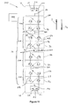
- a configurable power module according to a fifth embodiment of the invention is designated generally by reference numeral 170, and is shown schematically in Figure 11 .
- the fifth configurable power module 170 is similar to the third configurable power module 90 shown in Figure 5 and like features share the same reference numerals. However, the fifth configurable power module 170 instead includes a greater number of first and second connection module portions 56, 92, i.e. bi-directional module portions 104, and associated further capacitors 84. Typically the fifth configurable power module 170 includes 10 or so such bi-directional module portions 104.
- Each of the first and second and further capacitors 34, 46, 84 again has a surge arrestor connected in parallel therewith but these are omitted from each of Figures 11 and 12(a) to 12(d) for the sake of clarity.
- the fifth configurable power module 170 again includes a second control unit 144 which is similarly arranged in operative communication with each of the first and second sub-modules 12, 14 and the connection module 16, i.e. the plurality of first and second connection module portions 56, 92.
- the second control unit 144 in use again configures the fifth configurable power module 170 to operate in a normal mode, and it also configures the fifth configurable power module 170 to operate in a first fault blocking mode in which it blocks current flowing in the first direction D 1 flowing between the first and second connection terminals 24, 42, and in a second fault blocking mode in which it blocks current flowing in the second direction D 2 between the first and second connection terminals 24, 42.
- the second control unit 144 switches off all of the first, second, third and fourth switching elements 20, 22, 38, 40 in the first and second sub-modules 12, 14, and operates each of the first, second, third and fourth further bi-directional current flow control elements 60, 62, 96, 98 in each of the plurality of first and second connection module portions 56, 92 to block current flow therethrough.
- the fifth configurable power module 170 is able to block current flowing in the first direction D 1 between the first and second connection terminals 24, 42, i.e. in a similar manner to that shown in Figure 9(a) in connection with the fourth configurable power module 140, and also block current flowing in the second direction D 2 between the first and second connection terminal 24, 42, i.e. as shown in Figure 12(a) .
- the fifth configurable power module 170 when configured to operate in this normal mode it presents a high impendence to any current attempting to flow from the second connection terminal 42 to the first connection terminal 24 and vice versa.
- the second control unit 144 When configuring the fifth configurable power module 170 to operate in the first fault blocking mode the second control unit 144 carries out the essentially the same operations in the same order as it does in relation to the fourth configurable power module 140 when configured to operate in its fault blocking mode, i.e. to oppose and extinguish a fault current I Fault flowing in the first direction D 1 .
- the second control unit 144 carries out the following operations in the following order.
- the anti-parallel diode 32 in each of the first and second further bi-directional current flow control elements 60, 62 allows such current flow and so there is no need for the second control unit 144 to physically switch on each of these elements 60, 62.
- the fault current I Fault flows directly through the fifth configurable power module 170 and is again shared between the first and second limbs 48, 52, and the corresponding string of first and third 60, 96 or second and fourth 62, 98 further bi-directional current flow control elements such that lower conduction losses arise.
- the second control unit 144 then switches off the second and third switching elements 22, 38 to direct the fault current I Fault to flow through each of the plurality of energy storage devices 26, 44, 82, i.e. each of the first, second and further capacitors 34, 46, 84 so as to store energy, i.e. charge, in each of the first, second and further capacitors 34, 46, 84, i.e. as shown in Figure 12(c) .
- the second control unit 144 operates the connection module 16 in its second connection mode, i.e. switches off each of the first, second, third and fourth further bi-directional current flow control elements 60, 62, 96, 98 in the various first and second connection module portions 56, 92 in order to establish a second series connection between all of the capacitors 34, 46, 84 via the respective second unidirectional current flow control element 100, i.e. second diode 102 of each second connection module portion 92, i.e. as shown in Figure 12(d) .
- each of the capacitors 34, 46, 84 to combine and generate a blocking voltage which is essentially equal to the sum of the voltage, i.e. charge, across each of the capacitors 34, 46, 84 to oppose the fault current I Fault flowing in the second direction D 2 and thereby extinguish the fault current I Fault .
- Such switching off of the first, second, third and fourth further bi-directional current flow control elements 60, 62, 96, 98, and switching off of the third and fourth further bi-directional current flow control elements 96, 98 in particular, may again be done progressively, e.g. in stages, in order to modify the waveform shape of the fault current I Fault .
- the fifth configurable power module 170 may be similarly incorporated in a DC circuit breaker apparatus of the type shown in Figure 10 .
Landscapes
- Engineering & Computer Science (AREA)
- Power Engineering (AREA)
- Inverter Devices (AREA)
- Charge And Discharge Circuits For Batteries Or The Like (AREA)
Abstract
Description
- This invention relates to a configurable power module for use in a power transmission network, and more particularly for use in a high voltage direct current (HVDC) power transmission network, and to each of a voltage source converter and a direct current circuit breaker apparatus including such a module, as well as methods of configuring such a module.
- According to a first aspect of the invention there is provided a configurable power module, for use in a power transmission network, comprising:
- a first sub-module including a first pair of series-connected switching elements separated by a first connection terminal and connected in parallel with a first energy storage device; and
- a second sub-module including a second pair of series-connected switching elements separated by a second connection terminal and connected in parallel with a second energy storage device,
- the first and second sub-modules being interconnected by a connection module operable to interconnect the first and second sub-modules in first and second connection modes, the connection module in the first connection mode establishing a parallel connection between the first and second energy storage devices which has bidirectional current flow characteristics, and the connection module in the second connection mode interconnecting the first and second energy storage devices to permit the first and second energy storage devices to combine and generate a blocking voltage to oppose the flow of current between the first and second connection terminals.
- The inclusion of a connection module which is operable to interconnect first and second sub-modules in a first connection mode in which a parallel connection is established between first and second energy storage devices of corresponding sub-modules helps to reduce conduction losses within the configurable power module as a whole because current flow can be shared within the parallel connection during, e.g. normal operation of the configurable power module.
- In the meantime, the inclusion of a connection module which is additionally operable to interconnect the first and second sub-modules in a second connection mode in which the energy storage devices are able to combine and generate a blocking voltage to oppose the flow of current, e.g. a fault current, provides the configurable power module with further useful functionality and so helps to render it more cost effective than, e.g. conventional power modules.
- Optionally the connection module in the first connection mode establishes a parallel connection between the first and second energy storage devices which allows current to flow within the parallel connection in first and second opposite directions.
- Allowing current to flow within the parallel connection in first and second opposite directions permits the configurable power module to selectively provide a positive voltage source or a negative voltage source (as well as zero voltage) which can be used, for example, respectively to increase or decrease an output voltage at an alternating current (AC) terminal of a voltage source converter. This in turn renders the configurable power module of the invention particularly suitable for use in step-wise waveform generation to approximate sinusoidal voltage waveforms.
- Preferably the connection module includes:
- a first limb which extends between a first side of each of the first and second energy storage devices;
- a second limb which extends between a second side of each of the first and second energy storage devices; and
- a first connection module portion which includes a first pair of bi-directional current flow control elements, one bi-directional current flow control element lying within the first limb and the other bi-directional current flow control element lying within the second limb, each of the bi-directional current flow control elements selectively blocking current flow through the corresponding limb in the same first direction and permitting current to flow through the corresponding limb in the same second direction opposite the first direction.
- The inclusion of first and second limbs readily facilitates a parallel connection between the first and second sub-modules, while the inclusion of a bi-directional current flow control element in each limb provides a desired degree of control over the manner in which current flows through the connection module and in turn the first and second energy storage devices, such that fault current blocking in at least one first direction is possible.
- Optionally the first connection module portion further includes a first unidirectional current flow control element which permits current to flow therethrough in only one direction, the first unidirectional current flow control element interconnecting the first and second limbs to selectively establish a first series connection between the first and second energy storage devices and permit current to flow through the connection module in the first direction when each of the first pair of bi-directional current flow control elements is blocking current flow in the first direction.
- Providing the first connection module portion with a first unidirectional current flow control element increases the current flow path options through the connection module and facilitates fault current blocking in a second direction.
- The connection module may include a plurality of first connection module portions, and adjacent pairs of the first connection module portions may be separated by a further energy storage device connected in parallel between the first and second limbs.
- The inclusion of further parallel-connected energy storage devices allows the configurable power module to, if desired, generate a larger blocking voltage so as to adequately oppose a larger fault current.
- In a preferred embodiment of the invention the connection module additionally includes a second connection module portion including a second pair of bi-directional current flow control elements one of which lies within the first limb and the other of which lies within the second limb, each of the second pair of bi-directional current flow control elements selectively blocking current flow through the corresponding limb in the same second direction opposite the first direction in which each of the first pair of bi-directional current flow control elements of the first connection module portion selectively blocks current flow, the second module portion further including a second unidirectional current flow control element which interconnects the first and second limbs to establish a second series connection between the first and second energy storage devices and permits current to flow through the connection module in the second direction when each of the second pair of bi-directional current flow control elements is blocking current flow in the second direction, the second connection module portion lying next to the first connection portion to define a bi-directional module portion.
- The inclusion of such a second connection module portion allows the configurable power module of the invention to make use of a greater possible blocking voltage, e.g. as provided for by the inclusion in the power module of a larger number of energy storage devices, to oppose a fault current flowing in each of first and second directions.
- Optionally the connection module includes a plurality of first and second connection module portions lying next to one another to define respective bi-directional module portions, adjacent pairs of bi-directional module portions being separated by a further energy storage device connected in parallel between the first and second limbs.
- Such an arrangement helps to maximise the available blocking voltage in both first and second directions.
- Preferably the configurable power module further includes a control unit arranged in operative communication with each of the first and second sub-modules and the connection module, the control unit in use configuring the configurable power module to operate in a normal mode and in a fault blocking mode,
the control unit when configuring the configurable power module to operate in the normal mode operating the connection module in the first connection mode in which the parallel-connected energy storage devices combine with one another to form a larger combined energy store, and the control unit further switching on and off respective switching elements in the first and second modules to selectively direct current through the combined energy store such that the configurable power module is able to provide a voltage source commensurate in size with the larger size of the combined energy store, and
the control unit when configuring the configurable power module to operate in the fault blocking mode switching off all of the switching elements in the first and second sub-modules and operating the connection module in the second connection mode. - The inclusion of such a control unit provides the configurable power module with a first degree of desired functionality useful in voltage source converters.
- According to a second aspect of the invention there is provided a voltage source converter comprising at least one converter limb which includes first and second limb portions each of which includes at least one configurable power module as described hereinabove and at least one half-bridge module.
- Such a voltage source converter is able to utilise the lower capital cost and lower switching losses associated with the or each conventional half-bridge module while at the same time allowing the voltage source converter to block a fault current in a second direction in which half-bridge modules ordinarily are unable to block.
- The configurable power module may further include a control unit arranged in operative communication with each of the first and second sub-modules and the connection module, the control unit in use configuring the configurable power module to operate in a normal mode and in a fault blocking mode,
the control unit when configuring the configurable power module to operate in the normal mode switching off all of the switching elements in the first and second sub-modules and operating the bi-directional current flow control elements in the connection module to block current flow between the first and second connection terminals, and
the control unit when configuring the configurable power module to operate in the fault blocking mode carrying out the following operations in the following order: - (i) switching on all of the switching elements in the first and second sub-modules and operating the bi-directional current flow control elements in the connecting module to permit current flow between the first and second connection terminals;
- (ii) switching off one of the switching elements in each of the first and second sub-modules to direct current to flow through each of the plurality of energy storage devices and thereby store energy in each said energy storage device; and
- (iii) operating the connection module in its second connection mode to permit each of the plurality of energy storage devices to combine and generate a blocking voltage to oppose a fault current flowing between the first and second connection terminals.
- Preferably the control unit in use configures the configurable power module to operate in a first fault blocking mode to block a fault current flowing in the first direction between the first and second connection terminals, the control unit when so configuring the configurable power module carrying out the following operations in the following order:
- (i) switching on all of the switching elements in the first and second sub-modules and operating the bi-directional current flow control elements in the connection module to permit current flow in the first direction;
- (ii) switching off one of the switching elements in each of the first and second sub-modules to direct current to flow through each of the plurality of energy storage devices and thereby store energy in each said energy storage device; and
- (iii) operating the connection module in its second connection mode to permit each of the plurality of energy storage devices to combine and generate a blocking voltage to oppose a fault current flowing in the first direction.
- The control unit may in use additionally configure the configurable power module to operate in a second fault blocking mode to block a fault current flowing in the second direction between the first and second connection terminals, the control unit when so configuring the configurable power module carrying out the following operations in the following order:
- (i) switching on all of the switching elements in the first and second sub-modules and operating the bi-directional current flow control elements in the connection module to permit current flow in the second direction;
- (ii) switching off one of the switching elements in each of the first and second sub-modules to direct current to flow through each of the plurality of energy storage devices and thereby store energy in each said energy storage device; and
- (iii) operating the connection module in its second connection mode to permit each of the plurality of energy storage devices to combine and generate a blocking voltage to oppose a fault current flowing in the second direction.
- The inclusion of such a control unit provides the configurable power module with various a second degrees of desired functionality useful in direct current circuit breaker apparatuses.
- Optionally the control unit when operating the connection module in its second connection mode operates the connection module to interconnect the plurality of energy storage devices in series with one another.
- Interconnecting the plurality of energy storage devices in series with one another leads to a summing of the energy stored by each one such that when combined they are able together to generate a blocking voltage which is greater than that which each alone could generate, and so when combined in such a way the configurable power module is able to oppose a larger fault current.
- In another preferred embodiment of the invention the control unit when operating the connection module in its second connection mode progressively interconnects respective ones of the plurality of energy storage devices.
- Such progressive interconnecting of respective ones of the plurality of energy storage devices, i.e. interconnecting individual energy storage devices singularly or within small groups, allows the configurable power module to modify, i.e. sculpt, the shape of a fault current waveform, e.g. so as to give a low rate of change of current as the fault current is extinguished. Such sculpting of the fault current waveform means that extinguishing the fault current can be achieved at a point when the energy storage in the various energy storage devices within the configurable power module is minimised so as to minimise also any corresponding over voltage.
- Preferably each energy storage device includes a surge arrester connected in parallel therewith.
- The inclusion of such a surge arrester associated with each energy storage device limits the energy stored by each energy storage device to a defined level.
- According to a third aspect of the invention there is provided a direct current circuit breaker apparatus comprising main and ancillary current paths, the main current path including an electronic switch and a mechanical circuit breaker arranged in series with one another, and the ancillary current path including a configurable power module as described hereinabove.
- The configurable power module within such a circuit breaker apparatus presents a high impedance during operation in its normal mode, and when configured to operate in its fault blocking mode is able initially to present a low impedance to a fault current, then control the rate of change of voltage as contacts in the mechanical circuit breaker begin to part, before controlling transient over voltage once the said contacts are open.
- According to a fourth aspect of the invention there is provided a method of configuring a configurable power module according as described hereinabove wherein:
- configuring the configurable power module to operate in a normal mode comprises the steps of:
- (a) operating the connection module in the first connection mode in which the parallel-connected energy storage devices combine with one another to form a larger combined energy store; and
- (b) switching on and off respective switching elements in the first and second modules to selectively direct current through the combined energy store such that the configurable power module provides a voltage source commensurate in size with the larger size of the combined energy store; and
configuring the configurable power module to operate in a fault blocking mode comprises the steps of: - (c) switching off all of the switching elements in the first and second sub-modules; and
- (d) operating the connection module in the second connection mode.
- Such a method provides the configurable power module with a first degree of desired functionality useful in voltage source converters.
- According to a fifth aspect of the invention there is provided a method of configuring a configurable power module as described hereinabove wherein:
- configuring the configurable power module to operate in a normal mode comprises the steps of:
- (a) switching off all of the switching elements in the first and second sub-modules; and
- (b) operating the bi-directional current flow control elements in the connection module to block current flow between the first and second connection terminals; and
- configuring the configurable power module to operate in the fault blocking mode comprises in the following order the steps of:
- (c) switching on all of the switching elements in the first and second sub-modules and operating the bi-directional current flow control elements in the connection module to permit current flow between the first and second connection terminals;
- (d) switching off one of the switching elements in each of the first and second sub-modules to direct current to flow through each of the plurality of energy storage devices and thereby store energy in each said energy storage device; and
- (e) operating the connection module in its second connection mode to permit each of the plurality of energy storage devices to combine and generate a blocking voltage to oppose a fault current flowing between the first and second connection terminals.
- Such a method provides the configurable power module with a second degree of desired functionality which is useful in direct current circuit breaker apparatuses.
- There now follows a description of preferred embodiments of the invention, by way of non-limiting example, with reference being made to the following figures in which:
-
Figure 1(a) shows a schematic view of a configurable power module according to a first embodiment of the invention; -
Figure 1(b) shows a further schematic view of the configurable power module shown inFigure 1 (a) when configured to operate in a normal mode; -
Figures 2(a) to 2(d) illustrate schematically operation of the configurable power module shown inFigure 1 in respective fault blocking modes; -
Figure 3 shows a schematic view of a configurable power module according to a second embodiment of the invention; -
Figures 4(a) and 4(b) illustrate schematically operation of the configurable power module shown inFigure 3 in respective fault blocking modes; -
Figure 5 shows a schematic view of a configurable power module according to a third embodiment of the invention; -
Figures 6(a) and 6(b) illustrate schematically operation of the configurable power module shown inFigure 5 in respective fault blocking modes; -
Figure 7 shows a schematic view of a voltage source converter incorporating a configurable power module according to an embodiment of the invention; -
Figure 8 shows a schematic view of a configurable power module according to a fourth embodiment of the invention; -
Figures 9(a) and9(d) illustrate schematically operation of the configurable power module shown inFigure 8 in normal and fault blocking modes; -
Figure 10 shows a schematic view of a direct current circuit breaker apparatus incorporating the configurable power module shown inFigure 8 ; -
Figure 11 shows a schematic view of a configurable power module according to a fifth embodiment of the invention; and -
Figures 12(a) to 12(d) illustrate schematically operation of the configurable power module shown inFigure 11 . - A configurable power module according to a first embodiment of the invention is designated generally by
reference numeral 10. - The first
configurable power module 10 includes first andsecond sub-modules connection module 16 that is operable to interconnect the first andsecond sub-modules - The first sub-module 12 has a
first pair 18 of first andsecond switching elements first connection terminal 24, and which are connected in parallel with a first energy storage device 26. - In the embodiment shown each of the switching
elements semiconductor device 30 in the form of, e.g. an Insulated Gate Bipolar Transistor (IGBT), which is connected in parallel with ananti-parallel diode 32. It is, however, possible to use anothersemiconductor device 30 instead of an IGBT. - In addition, in the embodiment shown the first energy storage device 26 is a
first capacitor 34, although other forms of energy storage device are also possible. - The second sub-module 14 has a
second pair 36 of third andfourth switching elements second connection terminal 42, and which are connected in parallel with a second energy storage device 44. Each of the third andfourth switching elements second capacitor 46, although other forms of energy storage device are again also possible. - The
connection module 16 includes afirst limb 48 which extends between a first side 50 of each of the first and second energy storage devices 26, 44, i.e. the first andsecond capacitors connection module 16 also includes asecond limb 52 which extends between asecond side 54 of each of the first andsecond capacitors second capacitors - In addition the
connection module 16 includes a firstconnection module portion 56 which includes afirst pair 58 of first and second further bi-directional currentflow control elements flow control element 60 lies within thefirst limb 48 while the second lies within thesecond limb 52. - In the embodiment shown each of the further bi-directional current
flow control elements fourth switching elements flow control element limb same limb flow control elements limb limb flow control elements - The first
connection module portion 56 also includes a first unidirectional currentflow control element 64 which permits current flow therethrough in only one direction. In the embodiment shown the first unidirectional currentflow control element 64 is afirst diode 66. - The
first diode 66 interconnects the first andsecond limbs second side 54 of thesecond capacitor 46 to the first side 50 of thefirst capacitor 34 so as to selectively establish a first series connection between the first andsecond capacitors connection module 16 in the first direction D1 when each of thefirst pair 58 of further bi-directional currentflow control elements - The first
configurable power module 10 also includes afirst control unit 68 which is arranged in operative communication with each of the first andsecond sub-modules connection module 16. - In use the
first control unit 68 configures the firstconfigurable power module 10 to operate in a normal mode and in a fault blocking mode. - When configuring the first
configurable power module 10 to operate in the normal mode thefirst control unit 68 operates theconnection module 16 in the first connection mode and, more particularly, establishes a parallel connection between the first andsecond capacitors flow control elements second capacitors first control unit 68 combines the first andsecond capacitors second capacitors 34, 46). - Thereafter the
first control unit 68 switches on and offrespective switching elements capacitors configurable power module 10 provides a positive or negative voltage source commensurate in size with the larger size of the combinedcapacitors second capacitors second capacitors second capacitors - The
first control unit 68 also controls switching of the first, second, third andfourth switching elements second capacitors configurable power module 10 to provide a zero voltage source while permitting current to flow therethrough in each of the first and second directions D1, D2. - In a particular normal mode of operation the
first control unit 68 switches off thethird switching element 38 and switches on thefourth switching element 40 in thesecond pair 36 of switching elements (or vice versa) to arrange the firstconfigurable power module 10 in a pseudo half-bridge arrangement. Such an arrangement is able only to provide a positive voltage source or a zero voltage source, while conducting current in both directions, but it has lower switching losses than thesame module 10 operated in a conventional full-bridge arrangement, as described above. - When configuring the first
configurable power module 10 to operate in the fault blocking mode thefirst control unit 68 switches off all of the first, second, third andfourth switching elements second pairs connection module 16 in its second connection mode. - When operating the
connection module 16 in its second connection mode thefirst control unit 68 also switches off both of the first and second further bi-directional currentflow control elements - In response to a current, e.g. a fault current IFault, flowing in the second direction D2, i.e. as shown in
Figure 2(a) , theanti-parallel diode 32 in each of the first andfourth switching elements flow control elements second capacitors configurable power module 10. - The first and
second capacitors second capacitors - In response to a fault current IFault flowing in the first direction D1, i.e. as shown in
Figure 2(b) , theanti-parallel diode 32 in each of the second andthird switching elements flow control element 64, i.e. thefirst diode 66, act to interconnect the first andsecond capacitors second capacitors configurable power module 10. - However, because the first and
second capacitors second capacitors - A
configurable power module 80 according to a second embodiment of the invention is illustrated schematically inFigure 3 . The secondconfigurable power module 80 is similar to the firstconfigurable power module 10 and like features share the same reference numerals. - However the second
configurable power module 80 instead includes two firstconnection module portions 56 which are separated by a furtherenergy storage device 82, in the form of afurther capacitor 84, which is connected in parallel between the first andsecond limbs - Still further embodiments of the invention may include more than two first
connection module portions 56 together with a similarly greater number of associated furtherenergy storage devices 82, e.g.further capacitors 84. - In use the
first control unit 68 configures the secondconfigurable power module 80 to operate in normal and fault blocking modes which are very similar to those of the firstconfigurable power module 10. - When configuring the second
configurable power module 80 to operate in the normal mode thefirst control unit 68 again operates theconnection module 16 in a first connection mode to establish a parallel connection between the first, second andfurther capacitors flow control elements connection module portions 56. - In this manner the
first control unit 68 combines the first, second andfurther capacitors further capacitors - Thereafter the
first control unit 68 switches on and offrespective switching elements capacitors configurable power module 80 provides a positive or negative voltage source commensurate in size with the larger size of the combinedcapacitors - When configuring the second
configurable power module 80 to operate in the fault blocking mode thefirst control unit 68 switches off all of the first, second, third andfourth switching elements second pairs connection module 16 in a second connection mode. - When operating the
connection module 16 in its second connection mode thefirst control unit 68 again switches off both of the first and second further bi-directional currentflow control elements connection module portions 56. - In response to a fault current IFault flowing in the second direction D2, i.e. as shown in
Figure 4(a) , theanti-parallel diode 32 in each of the first andfourth switching elements flow control elements connection module portions 56 acts to interconnect the first, second andfurther capacitors configurable power module 80. - The first, second and
further capacitors further capacitors - In response to a fault current IFault flowing in the first direction D1, i.e. as shown in
Figure 4(b) , theanti-parallel diode 32 in each of the second andthird switching elements flow control element 64, i.e. thefirst diode 66, in each firstconnection module portion 56 act to interconnect the first, second andfurther capacitors further capacitors configurable power module 80. - However the first, second and
further capacitors further capacitors -
Figure 5 illustrates schematically aconfigurable power module 90 according to a third embodiment of the invention. - The third
configurable power module 90 is similar to the firstconfigurable power module 10 and like features share the same reference numerals. - The third
configurable power module 90 differs from the firstconfigurable power module 10 in that it includes aconnection module 16 which additionally includes a secondconnection module portion 92. - The second
connection module portion 92 has asecond pair 94 of third and fourth further bi-directional currentflow control elements flow control element 96 lies within thefirst limb 48 and the fourth further bi-directional currentflow control element 98 lies within thesecond limb 52. The third and fourth further bi-directional currentflow control elements limb flow control elements - The second
connection module portion 92 also includes a second unidirectional currentflow control element 100 in the form of asecond diode 102. - The
second diode 102 again interconnects the first andsecond limbs second side 54 of thefirst capacitor 34 to the first side 50 of the second capacitor 46 (via the second further bi-directional current flow control element 62) so as to selectively establish a second series connection between the first andsecond capacitors connection module 16 in the second direction D2 when each of the first andsecond pairs flow control elements - The second
connection module portion 92 lies immediately next to the firstconnection module portion 56 and in this manner the twoconnection module portions bi-directional module portion 104. - Further embodiments of the invention may include a
connection module 16 which has a plurality of suchbi-directional module portions 104, adjacent pairs of which are separated by a still further energy storage device, e.g. a still further capacitor, connected in parallel between the first andsecond limbs - In use the
first control unit 68 configures the thirdconfigurable power module 90 to again operate in normal and fault blocking modes which are similar to those of the firstconfigurable power module 10. - When configuring the third
configurable power module 90 to operate in the normal mode theconnection module 16 is operated in the first connection mode, i.e. to establish a parallel connection between the first andsecond capacitors flow control elements second pair 94 of switching elements in the secondconnection module portion 92. - Thereafter it functions in essentially the same manner as the first
configurable power module 10. - When configuring the third
configurable power module 90 to operate in the fault blocking mode theconnection module 16 is operated in its second connection mode by additionally switching off both of the third and fourth further bi-directional currentflow control elements connection module portion 92. - In response to a fault current IFault flowing in the first direction D1, i.e. as shown in
Figure 6(b) , the first unidirectional currentflow control element 64, i.e. thefirst diode 66, in the firstconnection module portion 56 cooperates with theanti-parallel diode 32 in the fourth bi-directional currentflow control element 98 of the secondconnection module portion 92 to interconnect the first andsecond capacitors second capacitors configurable power module 90. Moreover, the first andsecond capacitors second capacitors - In response to a fault current IFault flowing in the second direction D2, i.e. as shown in
Figure 6(a) , the second unidirectional currentflow control element 100, i.e. thesecond diode 102, in the secondconnection module portion 92 cooperates with theanti-parallel diode 32 in the second further bi-directional currentflow control element 62 of the firstconnection module portion 56 to interconnect the first andsecond capacitors second capacitors second capacitors second capacitors -
Figure 7 shows a schematic view of avoltage source converter 110 which includes first and second direct current (DC)terminals third converter limb - Each
converter limb second limb portions terminal 126. - Each
limb portion AC terminal 126 and a corresponding one of the first or thesecond DC terminal - Each chain-link converter 128 includes a plurality of series connected modules 130 which in turn includes a mix of conventional half-
bridge modules 132 and firstconfigurable power modules 10. - For example, if one third of the series connected modules 130 are first
configurable power modules 10 then the total blocking voltage generated against a fault current IFault flowing in the first direction D1, i.e. as shown inFigure 2(b) , is given by
- Where VDC is the maximum voltage an individual first or
second capacitor second DC terminals 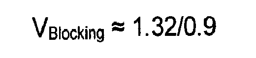

which is adequate to quickly stop the fault current IFault flowing in the first direction D1. - If utilising the second
configurable power module 80 it is possible to use fewer of thesemodules 80 because each is able to generate a greater blocking voltage in the first direction D1 than the firstconfigurable power module 10. - For example, having only 22% of the series connected modules 130 as second
configurable power modules 80 still gives a total blocking voltage as follows
i.e.
which is again adequate to quickly stop the fault current IFault flowing in the first direction D1. - A configurable power module according to a fourth embodiment of the invention is designated generally by
reference numeral 140, and is shown schematically inFigure 8 . - The fourth
configurable power module 140 is similar to the secondconfigurable power module 80 but instead includes a greater number of firstconnection module portions 56 and associatedfurther capacitors 84. Typically the fourthconfigurable power module 140 includes 10 or sosuch module portions 56. - In addition, each of the first and second and
further capacitors surge arrestor 142 connected in parallel therewith. - The fourth
configurable power module 140 also includes asecond control unit 144 which is again arranged in operative communication with each of the first andsecond sub-modules connection module 16. - The
second control unit 144 in use again configures the fourthconfigurable power module 140 to operate in a normal mode and in a fault blocking mode. - When configuring the fourth
configurable power module 140 to operate in the normal mode thesecond control unit 144 switches off all of the first, second, third andfourth switching elements second sub-modules flow control elements connection module portions 56 to block current flow in the first direction D1, i.e. as shown inFigure 9(a) . - Accordingly, when the fourth
configurable power module 140 is configured to operate in this normal mode it presents a high impendence to any current attempting to flow from thesecond connection terminal 42 to thefirst connection terminal 24. - When configuring the fourth
configurable power module 140 to operate in the fault blocking mode thesecond control unit 144 carries out the following operations in the following order. - It first switches on all of first, second, third and
fourth switching elements second sub-modules flow control elements connection module portions 56 to permit current flow in the first direction D1, i.e. as shown schematically inFigure 9(b) . - In this arrangement the fault current IFault flows directly through the fourth
configurable power module 140 and is shared between the first andsecond limbs flow control elements - The
second control unit 144 then switches off the first andfourth switching elements energy storage devices 26, 44, 82, i.e. each of the first, second andfurther capacitors further capacitors Figure 9(c) . - Thereafter the
second control unit 144 operates theconnection module 16 in its second connection mode, i.e. switches off each of the first and second further bi-directional currentflow control elements connection module portions 56 in order to establish a first series connection between all of thecapacitors flow control element 64, i.e.first diode 66 of each firstconnection module portion 56, i.e. as shown inFigure 9(d) . - This permits each of the
capacitors capacitors - Such switching off of the first and second further bi-directional current
flow control elements -
Figure 10 shows a schematic view of a DCcircuit breaker apparatus 150 in which the fourthconfigurable power module 140 is incorporated. - More particularly the DC
circuit breaker apparatus 150 includes main and ancillarycurrent paths - The main
current path 152 includes a low voltageelectronic switch 156 which blocks current flow through the maincurrent path 152 in the event of a fault arising. The maincurrent path 152 also includes amechanical circuit breaker 158 which is arranged in series with theelectronic switch 156. - The ancillary
current path 154 includes the fourthconfigurable power module 140 described above. - In use, in the absence of a fault, the fourth
configurable power module 140 is configured to operate in its normal mode so as to present a high impendence in the ancillarycurrent path 154. - Once a fault is detected, the low voltage
electronic switch 156 is opened and the fault current IFault is diverted from the maincurrent path 152 and into the ancillarycurrent path 154. - The
second control unit 144 then switches on, i.e. closes, all of the first, second, third andfourth switching elements flow control elements configurable power module 140 and associated ancillarycurrent path 154, with the said fault current IFault being shared between the first andsecond limbs connection module 16 as shown inFigure 9(b) . - When the main contacts of the
mechanical circuit breaker 158 are known, or assumed, to be opening then the first andfourth switching elements capacitors capacitor surge arrestor 142 level where upon the surge arrestors conduct, as shown inFigure 9(c) . As the surge arrestors conduct in the aforementioned manner they dissipate energy from the connected electrical system. - During this period, i.e. as the main contacts of the
mechanical circuit breaker 158 are opening, the rate of increase in voltage across the ancillarycurrent path 154, and hence across themechanical circuit breaker 158 is limited by the total parallel capacitance of thecapacitors - From this point forward selective first and second further bi-directional current
flow control elements capacitors first diodes 66 until all of thecapacitors Figure 9(d) and the ancillarycurrent path 154 generates the maximum blocking voltage to extinguish the fault current. - A configurable power module according to a fifth embodiment of the invention is designated generally by
reference numeral 170, and is shown schematically inFigure 11 . - The fifth
configurable power module 170 is similar to the thirdconfigurable power module 90 shown inFigure 5 and like features share the same reference numerals. However, the fifthconfigurable power module 170 instead includes a greater number of first and secondconnection module portions bi-directional module portions 104, and associatedfurther capacitors 84. Typically the fifthconfigurable power module 170 includes 10 or so suchbi-directional module portions 104. - Each of the first and second and
further capacitors Figures 11 and12(a) to12(d) for the sake of clarity. - The fifth
configurable power module 170 again includes asecond control unit 144 which is similarly arranged in operative communication with each of the first andsecond sub-modules connection module 16, i.e. the plurality of first and secondconnection module portions - The
second control unit 144 in use again configures the fifthconfigurable power module 170 to operate in a normal mode, and it also configures the fifthconfigurable power module 170 to operate in a first fault blocking mode in which it blocks current flowing in the first direction D1 flowing between the first andsecond connection terminals second connection terminals - When configuring the fifth
configurable power module 170 to operate in the normal mode thesecond control unit 144 switches off all of the first, second, third andfourth switching elements second sub-modules flow control elements connection module portions configurable power module 170 is able to block current flowing in the first direction D1 between the first andsecond connection terminals Figure 9(a) in connection with the fourthconfigurable power module 140, and also block current flowing in the second direction D2 between the first andsecond connection terminal Figure 12(a) . - Accordingly, when the fifth
configurable power module 170 is configured to operate in this normal mode it presents a high impendence to any current attempting to flow from thesecond connection terminal 42 to thefirst connection terminal 24 and vice versa. - When configuring the fifth
configurable power module 170 to operate in the first fault blocking mode thesecond control unit 144 carries out the essentially the same operations in the same order as it does in relation to the fourthconfigurable power module 140 when configured to operate in its fault blocking mode, i.e. to oppose and extinguish a fault current IFault flowing in the first direction D1. - In the meantime, when configuring the fifth
configurable power module 170 to operate in the second fault blocking mode thesecond control unit 144 carries out the following operations in the following order. - It first switches on all of first, second, third and
fourth switching elements second sub-modules flow control elements connection module portions Figure 12(b) . In this regard, theanti-parallel diode 32 in each of the first and second further bi-directional currentflow control elements second control unit 144 to physically switch on each of theseelements - In this arrangement the fault current IFault flows directly through the fifth
configurable power module 170 and is again shared between the first andsecond limbs - The
second control unit 144 then switches off the second andthird switching elements energy storage devices 26, 44, 82, i.e. each of the first, second andfurther capacitors further capacitors Figure 12(c) . - Thereafter the
second control unit 144 operates theconnection module 16 in its second connection mode, i.e. switches off each of the first, second, third and fourth further bi-directional currentflow control elements connection module portions capacitors flow control element 100, i.e.second diode 102 of each secondconnection module portion 92, i.e. as shown inFigure 12(d) . - This permits each of the
capacitors capacitors - Such switching off of the first, second, third and fourth further bi-directional current
flow control elements flow control elements - The fifth
configurable power module 170 may be similarly incorporated in a DC circuit breaker apparatus of the type shown inFigure 10 .
Claims (18)
- A configurable power module, for use in a power transmission network, comprising:a first sub-module including a first pair of series-connected switching elements separated by a first connection terminal and connected in parallel with a first energy storage device; anda second sub-module including a second pair of series-connected switching elements separated by a second connection terminal and connected in parallel with a second energy storage device,the first and second sub-modules being interconnected by a connection module operable to interconnect the first and second sub-modules in first and second connection modes, the connection module in the first connection mode establishing a parallel connection between the first and second energy storage devices which has bidirectional current flow characteristics, and the connection module in the second connection mode interconnecting the first and second energy storage devices to permit the first and second energy storage devices to combine and generate a blocking voltage to oppose the flow of current between the first and second connection terminals.
- A configurable power module according to Claim 1 wherein the connection module in the first connection mode establishes a parallel connection between the first and second energy storage devices which allows current to flow within the parallel connection in first and second opposite directions.
- A configurable power module according to Claim 1 or Claim 2 wherein the connection module includes:a first limb which extends between a first side of each of the first and second energy storage devices;a second limb which extends between a second side of each of the first and second energy storage devices; anda first connection module portion which includes a first pair of bi-directional current flow control elements, one bi-directional current flow control element lying within the first limb and the other bi-directional current flow control element lying within the second limb, each of the bi-directional current flow control elements selectively blocking current flow through the corresponding limb in the same first direction and permitting current to flow through the corresponding limb in the same second direction opposite the first direction.
- A configurable power module according to Claim 3 wherein the first connection module portion further includes a first unidirectional current flow control element which permits current to flow therethrough in only one direction, the first unidirectional current flow control element interconnecting the first and second limbs to selectively establish a first series connection between the first and second energy storage devices and permit current to flow through the connection module in the first direction when each of the first pair of bi-directional current flow control elements is blocking current flow in the first direction.
- A configurable power module according to Claim 3 or Claim 4 wherein the connection module includes a plurality of first connection module portions, and adjacent pairs of the first connection module portions are separated by a further energy storage device connected in parallel between the first and second limbs.
- A configurable power module according to Claim 4 wherein the connection module additionally includes a second connection module portion including a second pair of bi-directional current flow control elements one of which lies within the first limb and the other of which lies within the second limb, each of the second pair of bi-directional current flow control elements selectively blocking current flow through the corresponding limb in the same second direction opposite the first direction in which each of the first pair of bi-directional current flow control elements of the first connection module portion selectively blocks current flow, the second module portion further including a second unidirectional current flow control element which interconnects the first and second limbs to establish a second series connection between the first and second energy storage devices and permits current to flow through the connection module in the second direction when each of the second pair of bi-directional current flow control elements is blocking current flow in the second direction, the second connection module portion lying next to the first connection portion to define a bi-directional module portion.
- A configurable power module according to Claim 6 wherein the connection module includes a plurality of first and second connection module portions lying next to one another to define respective bi-directional module portions, adjacent pairs of bi-directional module portions being separated by a further energy storage device connected in parallel between the first and second limbs.
- A configurable power module according to any preceding claim further including a control unit arranged in operative communication with each of the first and second sub-modules and the connection module, the control unit in use configuring the configurable power module to operate in a normal mode and in a fault blocking mode,
the control unit when configuring the configurable power module to operate in the normal mode operating the connection module in the first connection mode in which the parallel-connected energy storage devices combine with one another to form a larger combined energy store, and the control unit further switching on and off respective switching elements in the first and second sub-modules to selectively direct current through the combined energy store such that the configurable power module is able to provide a voltage source commensurate in size with the larger size of the combined energy store, and
the control unit when configuring the configurable power module to operate in the fault blocking mode switching off all of the switching elements in the first and second sub-modules and operating the connection module in the second connection mode. - A voltage source converter comprising at least one converter limb which includes first and second limb portions each of which includes at least one configurable power module according to any preceding claim and at least one half-bridge module.
- A configurable power module according to Claim 5 when dependent on Claim 4, or according to Claim 7, further including a control unit arranged in operative communication with each of the first and second sub-modules and the connection module, the control unit in use configuring the configurable power module to operate in a normal mode and in a fault blocking mode,
the control unit when configuring the configurable power module to operate in the normal mode switching off all of the switching elements in the first and second sub-modules and operating the bi-directional current flow control elements in the connection module to block current flow between the first and second connection terminals, and
the control unit when configuring the configurable power module to operate in the fault blocking mode carrying out the following operations in the following order:(i) switching on all of the switching elements in the first and second sub-modules and operating the bi-directional current flow control elements in the connection module to permit current flow between the first and second connection terminals;(ii) switching off one of the switching elements in each of the first and second sub-modules to direct current to flow through each of the plurality of energy storage devices and thereby store energy in each said energy storage device; and(iii) operating the connection module in its second connection mode to permit each of the plurality of energy storage devices to combine and generate a blocking voltage to oppose a fault current flowing between the first and second connection terminals. - A configurable power module according to Claim 10 wherein the control unit in use configures the configurable power module to operate in a first fault blocking mode to block a fault current flowing in the first direction between the first and second connection terminals, the control unit when so configuring the configurable power module carrying out the following operations in the following order:(i) switching on all of the switching elements in the first and second sub-modules and operating the bi-directional current flow control elements in the connection module to permit current flow in the first direction;(ii) switching off one of the switching elements in each of the first and second sub-modules to direct current to flow through each of the plurality of energy storage devices and thereby store energy in each said energy storage device; and(iii) operating the connection module in its second connection mode to permit each of the plurality of energy storage devices to combine and generate a blocking voltage to oppose a fault current flowing in the first direction.
- A configurable power module according to Claim 10 when dependent on Claim 7 wherein the control unit in use additionally configures the configurable power module to operate in a second fault blocking mode to block a fault current flowing in the second direction between the first and second connection terminals, the control unit when so configuring the configurable power module carrying out the following operations in the following order:(i) switching on all of the switching elements in the first and second sub-modules and operating the bi-directional current flow control elements in the connection module to permit current flow in the second direction;(ii) switching off one of the switching elements in each of the first and second sub-modules to direct current to flow through each of the plurality of energy storage devices and thereby store energy in each said energy storage device; and(iii) operating the connection module in its second connection mode to permit each of the plurality of energy storage devices to combine and generate a blocking voltage to oppose a fault current flowing in the second direction.
- A configurable power module according to any of Claims 10 to 12 wherein the control unit when operating the connection module in its second connection mode operates the connection module to interconnect the plurality of energy storage devices in series with one another.
- A configurable power module according to Claim 13 wherein the control unit when operating the connection module in its second connection mode progressively interconnects respective ones of the plurality of energy storage devices.
- A configurable power module according to any of Claims 10 to 14 wherein each energy storage device includes a surge arrester connected in parallel therewith.
- A direct current circuit breaker apparatus comprising main and ancillary current paths, the main current path including an electronic switch and a mechanical circuit breaker arranged in series with one another, and the ancillary current path including a configurable power module according to Claim 5 when dependent on Claim 4, or according to any of Claims 10 to 15.
- A method of configuring a configurable power module according to any of Claims 1 to 7 wherein:configuring the configurable power module to operate in a normal mode comprises the steps of:(a) operating the connection module in the first connection mode in which the parallel-connected energy storage devices combine with one another to form a larger combined energy store; and(b) switching on and off respective switching elements in the first and second modules to selectively direct current through the combined energy store such that the configurable power module provides a voltage source commensurate in size with the larger size of the combined energy store; and configuring the configurable power module to operate in a fault blocking mode comprises the steps of:(c) switching off all of the switching elements in the first and second sub-modules; and(d) operating the connection module in the second connection mode.
- A method of configuring a configurable power module according to Claim 5 when dependent on Claim 4, or according to Claim 7, wherein:configuring the configurable power module to operate in a normal mode comprises the steps of:(a) switching off all of the switching elements in the first and second sub-modules; and(b) operating the bi-directional current flow control elements in the connection module to block current flow between the first and second connection terminals; andconfiguring the configurable power module to operate in the fault blocking mode comprises in the following order the steps of:(c) switching on all of the switching elements in the first and second sub-modules and operating the bi-directional current flow control elements in the connection module to permit current flow between the first and second connection terminals;(d) switching off one of the switching elements in each of the first and second sub-modules to direct current to flow through each of the plurality of energy storage devices and thereby store energy in each said energy storage device; and(e) operating the connection module in its second connection mode to permit each of the plurality of energy storage devices to combine and generate a blocking voltage to oppose a fault current flowing between the first and second connection terminals.
Priority Applications (3)
| Application Number | Priority Date | Filing Date | Title |
|---|---|---|---|
| EP13185595.9A EP2852043A1 (en) | 2013-09-23 | 2013-09-23 | Improvements in or relating to power modules for use in power transmission networks |
| CN201480063851.9A CN105765848B (en) | 2013-09-23 | 2014-09-22 | Power modules used in power transmission networks and methods for their configuration |
| PCT/EP2014/070146 WO2015040218A1 (en) | 2013-09-23 | 2014-09-22 | Improvements in or relating to power modules for use in power transmission networks |
Applications Claiming Priority (1)
| Application Number | Priority Date | Filing Date | Title |
|---|---|---|---|
| EP13185595.9A EP2852043A1 (en) | 2013-09-23 | 2013-09-23 | Improvements in or relating to power modules for use in power transmission networks |
Publications (1)
| Publication Number | Publication Date |
|---|---|
| EP2852043A1 true EP2852043A1 (en) | 2015-03-25 |
Family
ID=49263130
Family Applications (1)
| Application Number | Title | Priority Date | Filing Date |
|---|---|---|---|
| EP13185595.9A Withdrawn EP2852043A1 (en) | 2013-09-23 | 2013-09-23 | Improvements in or relating to power modules for use in power transmission networks |
Country Status (3)
| Country | Link |
|---|---|
| EP (1) | EP2852043A1 (en) |
| CN (1) | CN105765848B (en) |
| WO (1) | WO2015040218A1 (en) |
Cited By (2)
| Publication number | Priority date | Publication date | Assignee | Title |
|---|---|---|---|---|
| US9831759B2 (en) | 2013-10-07 | 2017-11-28 | General Electric Technology Gmbh | Voltage source converter |
| WO2018113926A1 (en) * | 2016-12-20 | 2018-06-28 | Siemens Aktiengesellschaft | Power converter |
Families Citing this family (1)
| Publication number | Priority date | Publication date | Assignee | Title |
|---|---|---|---|---|
| CN112865046B (en) * | 2021-03-05 | 2025-07-11 | 全球能源互联网研究院有限公司 | A multifunctional multi-port hybrid DC circuit breaker and control method |
Citations (1)
| Publication number | Priority date | Publication date | Assignee | Title |
|---|---|---|---|---|
| WO2012072168A2 (en) * | 2010-11-30 | 2012-06-07 | Technische Universität München | Novel multi-level converter topology with the possibility of dynamically connecting individual modules in series and in parallel |
Family Cites Families (3)
| Publication number | Priority date | Publication date | Assignee | Title |
|---|---|---|---|---|
| WO2011012174A1 (en) * | 2009-07-31 | 2011-02-03 | Areva T&D Uk Limited | Converter with active fault current limitation |
| ES2466353T3 (en) * | 2010-04-08 | 2014-06-10 | Alstom Technology Ltd. | HVDC Hybrid Transformer |
| DE102012204046B3 (en) * | 2012-03-15 | 2013-08-14 | Siemens Aktiengesellschaft | Multicell converter |
-
2013
- 2013-09-23 EP EP13185595.9A patent/EP2852043A1/en not_active Withdrawn
-
2014
- 2014-09-22 WO PCT/EP2014/070146 patent/WO2015040218A1/en not_active Ceased
- 2014-09-22 CN CN201480063851.9A patent/CN105765848B/en not_active Expired - Fee Related
Patent Citations (1)
| Publication number | Priority date | Publication date | Assignee | Title |
|---|---|---|---|---|
| WO2012072168A2 (en) * | 2010-11-30 | 2012-06-07 | Technische Universität München | Novel multi-level converter topology with the possibility of dynamically connecting individual modules in series and in parallel |
Non-Patent Citations (1)
| Title |
|---|
| N AHMED ET AL: "Prospects and challenges of future HVDC SuperGrids with modular multilevel converters", EPE 2011, 1 January 2011 (2011-01-01), Birmingham, pages 1 - 10, XP055115782, ISBN: 978-9-07-581515-3 * |
Cited By (2)
| Publication number | Priority date | Publication date | Assignee | Title |
|---|---|---|---|---|
| US9831759B2 (en) | 2013-10-07 | 2017-11-28 | General Electric Technology Gmbh | Voltage source converter |
| WO2018113926A1 (en) * | 2016-12-20 | 2018-06-28 | Siemens Aktiengesellschaft | Power converter |
Also Published As
| Publication number | Publication date |
|---|---|
| CN105765848B (en) | 2019-05-14 |
| WO2015040218A1 (en) | 2015-03-26 |
| CN105765848A (en) | 2016-07-13 |
Similar Documents
| Publication | Publication Date | Title |
|---|---|---|
| EP2781013B1 (en) | A power electronic module | |
| US9780557B2 (en) | Electrical apparatus | |
| US10224712B2 (en) | Current flow controller | |
| KR101698940B1 (en) | Power electronic converter | |
| CN104303384A (en) | Control circuit | |
| CN106165278A (en) | Energy Storage System | |
| EP2782239A1 (en) | Power electronic converter | |
| US9847642B2 (en) | Control circuit | |
| CN102520276A (en) | Integrated testing circuit for modular multi-level converter valve and control method of integrated testing circuit | |
| CN110352558A (en) | Switching device for separating current paths | |
| US20210135662A1 (en) | A protection arrangement for an mmc-hvdc sub-module | |
| US20160164296A1 (en) | Module | |
| EP2947741B1 (en) | Control circuit | |
| EP2849306A1 (en) | Voltage source converter | |
| EP2852019B1 (en) | Improvements in or relating to power modules for use in power transmission networks | |
| US20180115253A1 (en) | Improvements in or relating to electrical assemblies | |
| WO2015040218A1 (en) | Improvements in or relating to power modules for use in power transmission networks | |
| EP3251189B1 (en) | Scalable switchyard for interconnecting direct current power networks | |
| EP2852040A1 (en) | Module | |
| US10141732B2 (en) | Apparatus for switching in a DC voltage grid | |
| EP3007301A1 (en) | Current flow controller | |
| EP3020126A2 (en) | Dc to dc converter assembly | |
| EP3007300A1 (en) | Current flow controller |
Legal Events
| Date | Code | Title | Description |
|---|---|---|---|
| PUAI | Public reference made under article 153(3) epc to a published international application that has entered the european phase |
Free format text: ORIGINAL CODE: 0009012 |
|
| 17P | Request for examination filed |
Effective date: 20130923 |
|
| AK | Designated contracting states |
Kind code of ref document: A1 Designated state(s): AL AT BE BG CH CY CZ DE DK EE ES FI FR GB GR HR HU IE IS IT LI LT LU LV MC MK MT NL NO PL PT RO RS SE SI SK SM TR |
|
| AX | Request for extension of the european patent |
Extension state: BA ME |
|
| R17P | Request for examination filed (corrected) |
Effective date: 20150918 |
|
| RBV | Designated contracting states (corrected) |
Designated state(s): AL AT BE BG CH CY CZ DE DK EE ES FI FR GB GR HR HU IE IS IT LI LT LU LV MC MK MT NL NO PL PT RO RS SE SI SK SM TR |
|
| RAP1 | Party data changed (applicant data changed or rights of an application transferred) |
Owner name: GENERAL ELECTRIC TECHNOLOGY GMBH |
|
| 17Q | First examination report despatched |
Effective date: 20181205 |
|
| STAA | Information on the status of an ep patent application or granted ep patent |
Free format text: STATUS: THE APPLICATION IS DEEMED TO BE WITHDRAWN |
|
| 18D | Application deemed to be withdrawn |
Effective date: 20200206 |