EP2852020A1 - Power distribution architecture and aircraft comprising power distribution architecture - Google Patents
Power distribution architecture and aircraft comprising power distribution architecture Download PDFInfo
- Publication number
- EP2852020A1 EP2852020A1 EP13185149.5A EP13185149A EP2852020A1 EP 2852020 A1 EP2852020 A1 EP 2852020A1 EP 13185149 A EP13185149 A EP 13185149A EP 2852020 A1 EP2852020 A1 EP 2852020A1
- Authority
- EP
- European Patent Office
- Prior art keywords
- power supply
- power
- power distribution
- main
- supply lines
- Prior art date
- Legal status (The legal status is an assumption and is not a legal conclusion. Google has not performed a legal analysis and makes no representation as to the accuracy of the status listed.)
- Granted
Links
Images
Classifications
-
- H—ELECTRICITY
- H02—GENERATION; CONVERSION OR DISTRIBUTION OF ELECTRIC POWER
- H02J—ELECTRIC POWER NETWORKS; CIRCUIT ARRANGEMENTS OR SYSTEMS FOR SUPPLYING OR DISTRIBUTING ELECTRIC POWER; SYSTEMS FOR STORING ELECTRIC ENERGY
- H02J4/00—Circuit arrangements for mains or distribution networks not specified as AC or DC; Circuit arrangements for mains or distribution networks combining AC and DC sections or sub-networks
-
- H—ELECTRICITY
- H02—GENERATION; CONVERSION OR DISTRIBUTION OF ELECTRIC POWER
- H02H—EMERGENCY PROTECTIVE CIRCUIT ARRANGEMENTS
- H02H3/00—Emergency protective circuit arrangements for automatic disconnection directly responsive to an undesired change from normal electric working condition with or without subsequent reconnection ; integrated protection
- H02H3/20—Emergency protective circuit arrangements for automatic disconnection directly responsive to an undesired change from normal electric working condition with or without subsequent reconnection ; integrated protection responsive to excess voltage
-
- B—PERFORMING OPERATIONS; TRANSPORTING
- B60—VEHICLES IN GENERAL
- B60R—VEHICLES, VEHICLE FITTINGS, OR VEHICLE PARTS, NOT OTHERWISE PROVIDED FOR
- B60R16/00—Electric or fluid circuits specially adapted for vehicles and not otherwise provided for; Arrangement of elements of electric or fluid circuits specially adapted for vehicles and not otherwise provided for
- B60R16/02—Electric or fluid circuits specially adapted for vehicles and not otherwise provided for; Arrangement of elements of electric or fluid circuits specially adapted for vehicles and not otherwise provided for electric constitutive elements
- B60R16/03—Electric or fluid circuits specially adapted for vehicles and not otherwise provided for; Arrangement of elements of electric or fluid circuits specially adapted for vehicles and not otherwise provided for electric constitutive elements for supply of electrical power to vehicle subsystems or for
-
- H—ELECTRICITY
- H02—GENERATION; CONVERSION OR DISTRIBUTION OF ELECTRIC POWER
- H02J—ELECTRIC POWER NETWORKS; CIRCUIT ARRANGEMENTS OR SYSTEMS FOR SUPPLYING OR DISTRIBUTING ELECTRIC POWER; SYSTEMS FOR STORING ELECTRIC ENERGY
- H02J2105/00—Networks for supplying or distributing electric power characterised by their spatial reach or by the load
- H02J2105/30—Networks for supplying or distributing electric power characterised by their spatial reach or by the load the load networks being external to vehicles, i.e. exchanging power with vehicles
- H02J2105/32—Networks for supplying or distributing electric power characterised by their spatial reach or by the load the load networks being external to vehicles, i.e. exchanging power with vehicles for aircrafts
Definitions
- the present invention relates to a power distribution architecture and an aircraft comprising a power distribution architecture, in particular for the power distribution among cabin and cargo loads in an aircraft.
- Modern aircraft power distribution architectures usually employ solid state power controller (SSPC) devices.
- SSPC solid state power controller
- the underlying principle for a SSPC is based upon one or more semiconductor switching devices coupled in series with a sensing device for detecting the switch current.
- a control unit is configured to implement guarding functions for the switching devices in case of a failure in any of the components of the SSPC device.
- Such SSPC devices are usually employed in so-called secondary power distribution boxes (SPDBs) of aircraft which provide cabin and cargo loads of the aircraft with electrical power.
- SPDBs secondary power distribution boxes
- the power supply lines are commonly additionally protected by so-called remote controlled circuit breakers (RCCBs) which are implemented in the power supply lines between the power supply and the SPDBs and which protect the loads against overloading in the case of insulation or equipment faults.
- RCCBs remote controlled circuit breakers
- Supply lines are usually designed with a specific load capacity so that after exceeding the maximum load capacity the respective RCCBs and SSPCs will trip and cause the power supply for the respective power supply line to be shut down.
- multiple cabin and cargo loads will have to be supplied with power.
- a trade-off has usually to be made between the number of separately protected power supply lines and the number of loads commonly supplied by a single supply line.
- the usage of loads in an aircraft may vary a lot, particularly depending on the flight phase, the time of the day, the types of loads and similar circumstances. Thus, load management in an aircraft is a daunting task.
- WO 2010/037934 A2 discloses methods and systems for supplying and distributing electrical power of several sources on a power network while ensuring the continuity of power supply in the case of a failure or interruption of one of the sources.
- a first aspect of the invention is directed to a power distribution architecture, comprising at least one power distribution box including at least two solid state power controllers, SSPCs, at least two main power supply lines, each of the main power supply lines being coupled to a respective one of the SSPCs and being configured to supply power to the respective one of the SSPCs, at least two main remote controlled circuit breakers, RCCBs, each of the at least two main RCCBs being coupled in a respective one of the main power supply lines, and at least one balancing RCCB coupled in a power balancing path connected between two of the main power supply lines.
- a second aspect of the invention is directed to an aircraft, comprising a power distribution architecture according to the first aspect of the invention.
- the idea on which the present invention is based is to combine the advantages of power supply line separation for loads or load groups with selective interconnectivity between separate power supply lines via protection elements in load balancing paths.
- this achieves power supply line redundancy for different loads or load groups so that the peak load is increased.
- loads may be more flexibly associated with load groups while keeping the number of overall load groups larger.
- defect or overload in one of the loads or load groups the remaining load groups may continue to operate.
- the parallel power supply line topology with security enhanced interconnection lines allows for the selective shutdown of specific power supply lines and their associated load groups, respectively. This is especially advantageous for separating safety-critical and non-safety-critical loads like flight entertainment systems or ground supply loads on one hand and fire protections systems or emergency lighting systems on the other.
- the power distribution architecture may further comprise a power supply coupled to the at least two main power supply lines and configured to provide power to the SSPCs.
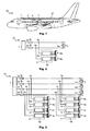
- Fig. 1 shows a schematic illustration of an aircraft 20 comprising a power distribution architecture 10 on board of the aircraft.
- the power distribution architecture 10 may in particular be used to distribute power from an on-board power supply 1 of the aircraft 20 to power distribution boxes 6 and 7 which are arranged in the aircraft 20.
- the power supply 1 may for example comprise a power source, for example a generator, a fuel cell or a high voltage battery.
- the power supply 1 may feed the power distribution boxes 6 and 7 via one or more power supply lines 2.
- the power distribution boxes 6 and 7 in turn may provide the supplied power to attached loads in the aircraft 20, for example cabin and cargo loads like in-flight entertainment systems, cabin lighting, galley, sanitary modules, electronic security systems or the like.
- the power supply line(s) 2 may for example run from the front of the aircraft 20 where a power supply 1 is typically located towards the back of the aircraft 20.
- the power distribution boxes 6 and 7 may be provided at convenient locations along the longitudinal extension of the aircraft 20, depending on where loads are located in the aircraft 20 that need to be supplied with electrical power.
- Fig. 2 shows an exemplary illustration of a power distribution architecture 10, for example for use in an aircraft 20 as exemplarily shown in conjunction with Fig. 1 .
- the power distribution architecture 10 includes a power supply 1 which is coupled to a power distribution box 6 which may for example be a secondary power distribution box (SPDB) of an aircraft.
- the power supply 1 may be coupled to two main power supply lines 2a, 2b which are configured to provide power to SSPCs or SSPC groups 6a, 6b which are in turn included in the power distribution box 6.
- Each of the power supply lines 2a and 2b may be coupled to a respective SSPC or SSPC group 6a or 6b, respectively, i.e. the SSPCs or SSPC groups 6a and 6b are electrically separate from each other and the power supply of each of the SSPCs or SSPC groups 6a and 6b is secured via a corresponding one of the main power supply lines 2a and 2b, respectively.
- a remote controlled circuit breaker (RCCB) 3a and 3b is coupled in the current path between the power supply 1 and the power distribution box 6.
- RCCB remote controlled circuit breaker
- a balancing remote controlled circuit breaker, RCCB, 5a may be coupled in a power balancing path 5 connected between the two main power supply lines 2a and 2b. Since the power supply lines 2a and 2b are commonly running approximately along the whole length of an aircraft with the power supply 1 being connected at the end of the aircraft's nose, the power balancing path 5 may advantageously be provided at the opposite end near the rear of the aircraft.
- Each of the SSPCs or SSPCs groups 6a and 6b may couple the power supply 1 with loads or load groups 8a and 8b, respectively.
- the SSPCs 6a and 6b may for example be hardware components including one or more controllable circuit breaking components which have to be enabled for the SSPC device to provide power from the power supply 1 to a particular one of the electrical loads 8a or 8b.
- the SSPCs 6a, 6b may be under control of a controlling unit that monitors the operational state of the elements of the SSPCs 6a, 6b.
- the controlling unit is able to take measures to shut down the power supply 1 and/or the SSPCs 6a, 6b for safety reasons.
- the required failure rates and failure response times are bounded by upper limits set by official regulations of aviation associations.
- the power supply 1 may for example be a generator, a fuel cell or a high voltage battery or accumulator, and may supply an input AC or DC voltage to the power distribution architecture 10.
- the main power supply lines 2a, 2b also called feeders, may be operated in parallel during normal operational conditions.
- the loads or load groups 8a and 8b are thus operated in parallel as well, just as the RCCBs 6a, 6b. This means that the current availability for each of the loads or load groups 8a and 8b is doubled by virtue of the power balancing path 5.
- the additional RCCB 5a is used to protect the wiring in the case of a failure, defect or overload.
- An overload would isolate the respective main power supply line 5 due to first the additional RCCB 5a opening and in short succession the respective main RCCB 3a or 3b.
- the power distribution box 6 is configured to shed all loads which may lead to an overload of the remaining main power supply lines 2a or 2b, while the remaining loads or load groups 8a and 8b remain operable.
- Fig. 3 schematically shows a power distribution architecture 10 which mainly differs for the power distribution architecture 10 in Fig. 2 in that four main power supply lines 2a, 2b, 2c, 2d are employed with main RCCBs 3a, 3b, 3c and 3d.
- Each of the main power supply lines 2a, 2b, 2c, 2d branches of at respective distribution nodes 4a, 4b, 4c, 4d to two power distribution boxes 6 and 7 with respective SSPCs or SSPCs groups 6a, 6b, 6c, 6d and 7a, 7b, 7c, 7d.
- the SSPCs 6a to 6d and 7a to 7d are configured to supply loads or load groups 8a to 8d and 9a to 9d, respectively, in each case.
- All main power supply lines 2a, 2b, 2c, 2d may be interconnected at a common neutral point.
- the interconnection lines to the common neutral point may be power balancing paths 5 as well with additional RCCBs 5a, 5b and 5c - one for each interconnection between two main power supply lines 2a, 2b, 2c, 2d - coupled between the neutral point and the distribution nodes 4a, 4b, 4c, 4d. It may also be possible to provide power balancing paths between the distribution nodes 4a, 4b, 4c, 4d for two of the power distribution boxes 6, 7 as well.
- RCCB 5a, 5b, 5c in each of the main power supply lines 2a, 2b, 2c, 2d, i.e. four additional RCCBs in the architecture shown in Fig. 2 , and to interconnect the main power supply lines 2a, 2b, 2c, 2d with direct connections. This may prove advantageous in terms of ease of installation and RCCB placement.
- the number of power distribution boxes 6, 7 is exemplarily shown as two in Fig. 3 , however, any other number of power distribution boxes may be possible as well.
- the number of main power supply lines or feeders 2a to 2d is exemplarily shown as four in Fig. 3 , however, any other number of main power supply lines being coupled in parallel may be possible as well.
Landscapes
- Engineering & Computer Science (AREA)
- Power Engineering (AREA)
- Mechanical Engineering (AREA)
- Direct Current Feeding And Distribution (AREA)
Abstract
Description
- The present invention relates to a power distribution architecture and an aircraft comprising a power distribution architecture, in particular for the power distribution among cabin and cargo loads in an aircraft.
- Modern aircraft power distribution architectures usually employ solid state power controller (SSPC) devices. The underlying principle for a SSPC is based upon one or more semiconductor switching devices coupled in series with a sensing device for detecting the switch current. Depending on the detected switch current by the sensing device, a control unit is configured to implement guarding functions for the switching devices in case of a failure in any of the components of the SSPC device.
- Such SSPC devices are usually employed in so-called secondary power distribution boxes (SPDBs) of aircraft which provide cabin and cargo loads of the aircraft with electrical power. In order to ensure operation safety of the aircraft the power supply lines are commonly additionally protected by so-called remote controlled circuit breakers (RCCBs) which are implemented in the power supply lines between the power supply and the SPDBs and which protect the loads against overloading in the case of insulation or equipment faults.
- Supply lines are usually designed with a specific load capacity so that after exceeding the maximum load capacity the respective RCCBs and SSPCs will trip and cause the power supply for the respective power supply line to be shut down. Depending on the type of aircraft, multiple cabin and cargo loads will have to be supplied with power. A trade-off has usually to be made between the number of separately protected power supply lines and the number of loads commonly supplied by a single supply line. The usage of loads in an aircraft may vary a lot, particularly depending on the flight phase, the time of the day, the types of loads and similar circumstances. Thus, load management in an aircraft is a daunting task.
- The document
WO 2010/037934 A2 discloses methods and systems for supplying and distributing electrical power of several sources on a power network while ensuring the continuity of power supply in the case of a failure or interruption of one of the sources. - However, there is still a need for solutions which optimizes load management with as little additional hardware and safety-relevant components as possible.
- This object is achieved by a power distribution architecture having the features of
claim 1, and by an aircraft having the features of claim 3. - A first aspect of the invention is directed to a power distribution architecture, comprising at least one power distribution box including at least two solid state power controllers, SSPCs, at least two main power supply lines, each of the main power supply lines being coupled to a respective one of the SSPCs and being configured to supply power to the respective one of the SSPCs, at least two main remote controlled circuit breakers, RCCBs, each of the at least two main RCCBs being coupled in a respective one of the main power supply lines, and at least one balancing RCCB coupled in a power balancing path connected between two of the main power supply lines.
- A second aspect of the invention is directed to an aircraft, comprising a power distribution architecture according to the first aspect of the invention.
- The idea on which the present invention is based is to combine the advantages of power supply line separation for loads or load groups with selective interconnectivity between separate power supply lines via protection elements in load balancing paths.
- Advantageously, this achieves power supply line redundancy for different loads or load groups so that the peak load is increased. Thus, loads may be more flexibly associated with load groups while keeping the number of overall load groups larger. In the event of failure, defect or overload in one of the loads or load groups the remaining load groups may continue to operate.
- More importantly, this effect is achieved without significant additional wiring requirements which lead to less space taken up and less weight being generated by the power distribution architecture. Weight saving is particularly advantageous for applications in aviation and avionics.
- Furthermore, the parallel power supply line topology with security enhanced interconnection lines allows for the selective shutdown of specific power supply lines and their associated load groups, respectively. This is especially advantageous for separating safety-critical and non-safety-critical loads like flight entertainment systems or ground supply loads on one hand and fire protections systems or emergency lighting systems on the other.
- According to an embodiment of the power distribution architecture, the power distribution architecture may further comprise a power supply coupled to the at least two main power supply lines and configured to provide power to the SSPCs.
- The invention will be explained in greater detail with reference to exemplary embodiments depicted in the drawings as appended.
- The accompanying drawings are included to provide a further understanding of the present invention and are incorporated in and constitute a part of this specification. The drawings illustrate the embodiments of the present invention and together with the description serve to explain the principles of the invention. Other embodiments of the present invention and many of the intended advantages of the present invention will be readily appreciated as they become better understood by reference to the following detailed description. The elements of the drawings are not necessarily to scale relative to each other. Like reference numerals designate corresponding similar parts.
- Fig. 1
- schematically illustrates an aircraft including a power distribution architecture according to an embodiment of the invention.
- Fig. 2
- schematically illustrates a power distribution architecture for an aircraft according to a further embodiment of the invention.
- Fig. 3
- schematically illustrates a further power distribution architecture for an aircraft according to a further embodiment of the invention.
- In the figures, like reference numerals denote like or functionally like components, unless indicated otherwise. Although specific embodiments have been illustrated and described herein, it will be appreciated by those of ordinary skill in the art that a variety of alternate and/or equivalent implementations may be substituted for the specific embodiments shown and described without departing from the scope of the present invention. Generally, this application is intended to cover any adaptations or variations of the specific embodiments discussed herein.
-
Fig. 1 shows a schematic illustration of anaircraft 20 comprising apower distribution architecture 10 on board of the aircraft. Thepower distribution architecture 10 may in particular be used to distribute power from an on-board power supply 1 of theaircraft 20 topower distribution boxes aircraft 20. Thepower supply 1 may for example comprise a power source, for example a generator, a fuel cell or a high voltage battery. Thepower supply 1 may feed thepower distribution boxes power supply lines 2. Thepower distribution boxes aircraft 20, for example cabin and cargo loads like in-flight entertainment systems, cabin lighting, galley, sanitary modules, electronic security systems or the like. The power supply line(s) 2 may for example run from the front of theaircraft 20 where apower supply 1 is typically located towards the back of theaircraft 20. Thepower distribution boxes aircraft 20, depending on where loads are located in theaircraft 20 that need to be supplied with electrical power. -
Fig. 2 shows an exemplary illustration of apower distribution architecture 10, for example for use in anaircraft 20 as exemplarily shown in conjunction withFig. 1 . Thepower distribution architecture 10 includes apower supply 1 which is coupled to apower distribution box 6 which may for example be a secondary power distribution box (SPDB) of an aircraft. Thepower supply 1 may be coupled to two mainpower supply lines SSPC groups power distribution box 6. - Each of the
power supply lines SSPC group SSPC groups SSPC groups power supply lines - In each of the main
power supply lines power supply 1 and thepower distribution box 6. Between at least two of the mainpower supply lines power balancing path 5 connected between the two mainpower supply lines power supply lines power supply 1 being connected at the end of the aircraft's nose, thepower balancing path 5 may advantageously be provided at the opposite end near the rear of the aircraft. - Each of the SSPCs or
SSPCs groups power supply 1 with loads orload groups power supply 1 to a particular one of theelectrical loads SSPCs power distribution architecture 10 the controlling unit is able to take measures to shut down thepower supply 1 and/or theSSPCs - The
power supply 1 may for example be a generator, a fuel cell or a high voltage battery or accumulator, and may supply an input AC or DC voltage to thepower distribution architecture 10. In thepower distribution architecture 10 ofFig. 2 the mainpower supply lines load groups RCCBs load groups power balancing path 5. - The
additional RCCB 5a is used to protect the wiring in the case of a failure, defect or overload. An overload would isolate the respective mainpower supply line 5 due to first theadditional RCCB 5a opening and in short succession the respectivemain RCCB power distribution box 6 is configured to shed all loads which may lead to an overload of the remaining mainpower supply lines load groups -
Fig. 3 schematically shows apower distribution architecture 10 which mainly differs for thepower distribution architecture 10 inFig. 2 in that four mainpower supply lines main RCCBs power supply lines respective distribution nodes power distribution boxes SSPCs groups load groups 8a to 8d and 9a to 9d, respectively, in each case. - All main
power supply lines power balancing paths 5 as well withadditional RCCBs power supply lines distribution nodes distribution nodes power distribution boxes - It may also be possible to provide a respective
additional RCCB power supply lines Fig. 2 , and to interconnect the mainpower supply lines - The number of
power distribution boxes Fig. 3 , however, any other number of power distribution boxes may be possible as well. Similarly, the number of main power supply lines orfeeders 2a to 2d is exemplarily shown as four inFig. 3 , however, any other number of main power supply lines being coupled in parallel may be possible as well. - In the foregoing detailed description, various features are grouped together in one or more examples or examples with the purpose of streamlining the disclosure. It is to be understood that the above description is intended to be illustrative, and not restrictive. It is intended to cover all alternatives, modifications and equivalents. Many other examples will be apparent to one skilled in the art upon reviewing the above specification.
- The embodiments were chosen and described in order to best explain the principles of the invention and its practical applications, to thereby enable others skilled in the art to best utilize the invention and various embodiments with various modifications as are suited to the particular use contemplated. In the appended claims and throughout the specification, the terms "including" and "in which" are used as the plain-English equivalents of the respective terms "comprising" and "wherein," respectively. Furthermore, "a" or "one" does not exclude a plurality in the present case.
-
- 1
- Power supply
- 2
- Main power supply bus
- 2a
- Main power supply line
- 2b
- Main power supply line
- 2c
- Main power supply line
- 2d
- Main power supply line
- 3a
- Main remote controlled circuit breaker
- 3b
- Main remote controlled circuit breaker
- 3c
- Main remote controlled circuit breaker
- 3d
- Main remote controlled circuit breaker
- 4a
- Distribution node
- 4b
- Distribution node
- 4c
- Distribution node
- 4d
- Distribution node
- 5
- Power balancing path
- 5a
- Balancing remote controlled circuit breaker
- 5b
- Balancing remote controlled circuit breaker
- 5c
- Balancing remote controlled circuit breaker
- 6
- Power distribution box
- 6a
- Solid state power controller
- 6b
- Solid state power controller
- 6c
- Solid state power controller
- 6d
- Solid state power controller
- 7
- Power distribution box
- 7a
- Solid state power controller
- 7b
- Solid state power controller
- 7c
- Solid state power controller
- 7d
- Solid state power controller
- 8a
- Load group
- 8b
- Load group
- 8c
- Load group
- 8d
- Load group
- 9a
- Load group
- 9b
- Load group
- 9c
- Load group
- 9d
- Load group
- 10
- Power distribution architecture
- 20
- Aircraft
Claims (3)
- Power distribution architecture (10), comprising:at least one power distribution box (6; 7) including at least two solid state power controllers, SSPCs (6a, 6b, 6c, 6d; 7a, 7b, 7c, 7d);at least two main power supply lines (2a, 2b, 2c, 2d),each of the main power supply lines (2a, 2b, 2c, 2d) being coupled to a respective one of the SSPCs (6a, 6b, 6c, 6d; 7a, 7b, 7c, 7d) and being configured to supply power to the respective one of the SSPCs (6a, 6b, 6c, 6d;7a, 7b, 7c, 7d);at least two main remote controlled circuit breakers,RCCBs (3a, 3b, 3c, 3d), each of the at least two main RCCBs (3a, 3b, 3c, 3d) being coupled in a respective one of the main power supply lines (2a, 2b, 2c, 2d); andat least one balancing remote controlled circuit breaker,RCCB (5a, 5b, 5c), coupled in a power balancing path (5) connected between two of the main power supply lines (2a, 2b, 2c, 2d).
- The power distribution architecture (10) of claim 1, further comprising:a power supply (1) coupled to the at least two main power supply lines (2a, 2b, 2c, 2d) and configured to provide power to the SSPCs (6a, 6b, 6c, 6d; 7a, 7b, 7c, 7d).
- Aircraft, comprising a power distribution architecture (10) of one of the claims 1 and 2.
Priority Applications (2)
| Application Number | Priority Date | Filing Date | Title |
|---|---|---|---|
| EP13185149.5A EP2852020B1 (en) | 2013-09-19 | 2013-09-19 | Power distribution architecture and aircraft comprising power distribution architecture |
| US14/482,783 US20150076900A1 (en) | 2013-09-19 | 2014-09-10 | Power distribution architecture and aircraft comprising power distribution architecture |
Applications Claiming Priority (1)
| Application Number | Priority Date | Filing Date | Title |
|---|---|---|---|
| EP13185149.5A EP2852020B1 (en) | 2013-09-19 | 2013-09-19 | Power distribution architecture and aircraft comprising power distribution architecture |
Publications (2)
| Publication Number | Publication Date |
|---|---|
| EP2852020A1 true EP2852020A1 (en) | 2015-03-25 |
| EP2852020B1 EP2852020B1 (en) | 2019-12-04 |
Family
ID=49261442
Family Applications (1)
| Application Number | Title | Priority Date | Filing Date |
|---|---|---|---|
| EP13185149.5A Active EP2852020B1 (en) | 2013-09-19 | 2013-09-19 | Power distribution architecture and aircraft comprising power distribution architecture |
Country Status (2)
| Country | Link |
|---|---|
| US (1) | US20150076900A1 (en) |
| EP (1) | EP2852020B1 (en) |
Cited By (1)
| Publication number | Priority date | Publication date | Assignee | Title |
|---|---|---|---|---|
| EP3409591A1 (en) * | 2017-05-30 | 2018-12-05 | Bell Helicopter Textron Inc. | System and methof for controlling rotorcraft load priority |
Families Citing this family (4)
| Publication number | Priority date | Publication date | Assignee | Title |
|---|---|---|---|---|
| EP3037351A1 (en) * | 2014-12-23 | 2016-06-29 | Airbus Operations GmbH | Self sufficient galley system, method for operating electrical galley devices and aircraft having such a galley system |
| US10391957B2 (en) | 2016-04-05 | 2019-08-27 | Ford Global Technologies, Llc | Integrated power distribution system for a vehicle |
| US10101749B1 (en) | 2017-03-21 | 2018-10-16 | Bell Helicopter Textron Inc. | Combined airspeed and inertial data for rotorcraft longitudinal control |
| FR3088872B1 (en) * | 2018-11-27 | 2021-05-28 | Renault Sas | Electrical supply network on board a vehicle. |
Citations (4)
| Publication number | Priority date | Publication date | Assignee | Title |
|---|---|---|---|---|
| EP1914162A1 (en) * | 2006-10-16 | 2008-04-23 | Converteam Ltd | DC power distribution system |
| WO2010037934A2 (en) | 2008-10-01 | 2010-04-08 | Novatec Sa | Method for organising an electric network including a plurality of generators, distribution block and equipment |
| EP2230743A2 (en) * | 2009-03-16 | 2010-09-22 | GE Aviation Systems Limited | Electrical Power Distribution |
| EP2388881A2 (en) * | 2010-05-19 | 2011-11-23 | Hamilton Sundstrand Corporation | Bus-tie SSPCs for d.c. power distribution system |
Family Cites Families (5)
| Publication number | Priority date | Publication date | Assignee | Title |
|---|---|---|---|---|
| US7805204B2 (en) * | 2007-03-21 | 2010-09-28 | Honeywell International Inc. | Integrated electrical power distribution system using common building blocks |
| US8344545B2 (en) * | 2009-01-20 | 2013-01-01 | Honeywell International Inc. | Solid state power contactors based on no break power transfer method |
| EP2442425B1 (en) * | 2010-10-15 | 2016-03-30 | Airbus Defence and Space SA | Electrical power control system for a vehicle. |
| US9197056B2 (en) * | 2012-06-11 | 2015-11-24 | Honeywell International Inc. | Solid state power control system for aircraft high voltage DC power distribution |
| US20160336754A1 (en) * | 2015-05-13 | 2016-11-17 | Hamilton Sundstrand Corporation | High power solid state switches for aircraft |
-
2013
- 2013-09-19 EP EP13185149.5A patent/EP2852020B1/en active Active
-
2014
- 2014-09-10 US US14/482,783 patent/US20150076900A1/en not_active Abandoned
Patent Citations (4)
| Publication number | Priority date | Publication date | Assignee | Title |
|---|---|---|---|---|
| EP1914162A1 (en) * | 2006-10-16 | 2008-04-23 | Converteam Ltd | DC power distribution system |
| WO2010037934A2 (en) | 2008-10-01 | 2010-04-08 | Novatec Sa | Method for organising an electric network including a plurality of generators, distribution block and equipment |
| EP2230743A2 (en) * | 2009-03-16 | 2010-09-22 | GE Aviation Systems Limited | Electrical Power Distribution |
| EP2388881A2 (en) * | 2010-05-19 | 2011-11-23 | Hamilton Sundstrand Corporation | Bus-tie SSPCs for d.c. power distribution system |
Cited By (2)
| Publication number | Priority date | Publication date | Assignee | Title |
|---|---|---|---|---|
| EP3409591A1 (en) * | 2017-05-30 | 2018-12-05 | Bell Helicopter Textron Inc. | System and methof for controlling rotorcraft load priority |
| US10942527B2 (en) | 2017-05-30 | 2021-03-09 | Textron Innovations Inc. | System and method for controlling rotorcraft load priority |
Also Published As
| Publication number | Publication date |
|---|---|
| EP2852020B1 (en) | 2019-12-04 |
| US20150076900A1 (en) | 2015-03-19 |
Similar Documents
| Publication | Publication Date | Title |
|---|---|---|
| EP2442425B1 (en) | Electrical power control system for a vehicle. | |
| EP2945244B1 (en) | Power and data distribution module and method for power and data distribution in an airborne vehicle | |
| EP2704280B1 (en) | Power distribution cabinet | |
| US8148848B2 (en) | Solid state power controller (SSPC) used as bus tie breaker in electrical power distribution systems | |
| US7626798B2 (en) | Electronic load control unit (ELCU) used as bus tie breaker in electrical power distribution systems | |
| EP2852020B1 (en) | Power distribution architecture and aircraft comprising power distribution architecture | |
| EP2757647A2 (en) | Reconfigurable matrix-based power distribution architecture | |
| US9787092B2 (en) | Aircraft power management system and method for managing power supply in an aircraft | |
| US9172272B2 (en) | Electrical power distribution system | |
| CN108321855B (en) | High-current switch module of aircraft | |
| US9809321B2 (en) | Electrical power distribution system with localized distribution conversion units | |
| US11258254B2 (en) | Electrical distribution device comprising at least one power controller | |
| US9701417B2 (en) | Integrated power quality module | |
| US8755159B2 (en) | System of current protection of a primary electrical distribution box | |
| CN105375610B (en) | The power supply system of the circuit board of distribution system | |
| KR102427627B1 (en) | Inrush current limit circuit arrangement structure in a system having a plurality of load equipment and the systems having the arrangement structure | |
| ES2400152A2 (en) | An electrical system of an aircraft. (Machine-translation by Google Translate, not legally binding) | |
| US20250096581A1 (en) | Battery power supply architecture | |
| Kerlin | Electrical Power Distribution Boxes for small aircraft | |
| BR112019025136A2 (en) | electric energy storage system and electric power distribution set | |
| HK1182537A (en) | Assembly for an uninterrupted power supply | |
| HK1182535A (en) | Assembly for an uninterrupted power supply | |
| HK1182536A (en) | Assembly for an uninterrupted power supply |
Legal Events
| Date | Code | Title | Description |
|---|---|---|---|
| PUAI | Public reference made under article 153(3) epc to a published international application that has entered the european phase |
Free format text: ORIGINAL CODE: 0009012 |
|
| 17P | Request for examination filed |
Effective date: 20130919 |
|
| AK | Designated contracting states |
Kind code of ref document: A1 Designated state(s): AL AT BE BG CH CY CZ DE DK EE ES FI FR GB GR HR HU IE IS IT LI LT LU LV MC MK MT NL NO PL PT RO RS SE SI SK SM TR |
|
| AX | Request for extension of the european patent |
Extension state: BA ME |
|
| R17P | Request for examination filed (corrected) |
Effective date: 20150910 |
|
| RBV | Designated contracting states (corrected) |
Designated state(s): AL AT BE BG CH CY CZ DE DK EE ES FI FR GB GR HR HU IE IS IT LI LT LU LV MC MK MT NL NO PL PT RO RS SE SI SK SM TR |
|
| 17Q | First examination report despatched |
Effective date: 20160223 |
|
| STAA | Information on the status of an ep patent application or granted ep patent |
Free format text: STATUS: EXAMINATION IS IN PROGRESS |
|
| GRAP | Despatch of communication of intention to grant a patent |
Free format text: ORIGINAL CODE: EPIDOSNIGR1 |
|
| STAA | Information on the status of an ep patent application or granted ep patent |
Free format text: STATUS: GRANT OF PATENT IS INTENDED |
|
| INTG | Intention to grant announced |
Effective date: 20190814 |
|
| GRAS | Grant fee paid |
Free format text: ORIGINAL CODE: EPIDOSNIGR3 |
|
| GRAA | (expected) grant |
Free format text: ORIGINAL CODE: 0009210 |
|
| STAA | Information on the status of an ep patent application or granted ep patent |
Free format text: STATUS: THE PATENT HAS BEEN GRANTED |
|
| AK | Designated contracting states |
Kind code of ref document: B1 Designated state(s): AL AT BE BG CH CY CZ DE DK EE ES FI FR GB GR HR HU IE IS IT LI LT LU LV MC MK MT NL NO PL PT RO RS SE SI SK SM TR |
|
| REG | Reference to a national code |
Ref country code: GB Ref legal event code: FG4D |
|
| REG | Reference to a national code |
Ref country code: CH Ref legal event code: EP |
|
| REG | Reference to a national code |
Ref country code: AT Ref legal event code: REF Ref document number: 1210627 Country of ref document: AT Kind code of ref document: T Effective date: 20191215 |
|
| REG | Reference to a national code |
Ref country code: DE Ref legal event code: R096 Ref document number: 602013063535 Country of ref document: DE |
|
| REG | Reference to a national code |
Ref country code: IE Ref legal event code: FG4D |
|
| REG | Reference to a national code |
Ref country code: NL Ref legal event code: MP Effective date: 20191204 |
|
| REG | Reference to a national code |
Ref country code: LT Ref legal event code: MG4D |
|
| PG25 | Lapsed in a contracting state [announced via postgrant information from national office to epo] |
Ref country code: FI Free format text: LAPSE BECAUSE OF FAILURE TO SUBMIT A TRANSLATION OF THE DESCRIPTION OR TO PAY THE FEE WITHIN THE PRESCRIBED TIME-LIMIT Effective date: 20191204 Ref country code: LV Free format text: LAPSE BECAUSE OF FAILURE TO SUBMIT A TRANSLATION OF THE DESCRIPTION OR TO PAY THE FEE WITHIN THE PRESCRIBED TIME-LIMIT Effective date: 20191204 Ref country code: SE Free format text: LAPSE BECAUSE OF FAILURE TO SUBMIT A TRANSLATION OF THE DESCRIPTION OR TO PAY THE FEE WITHIN THE PRESCRIBED TIME-LIMIT Effective date: 20191204 Ref country code: NO Free format text: LAPSE BECAUSE OF FAILURE TO SUBMIT A TRANSLATION OF THE DESCRIPTION OR TO PAY THE FEE WITHIN THE PRESCRIBED TIME-LIMIT Effective date: 20200304 Ref country code: GR Free format text: LAPSE BECAUSE OF FAILURE TO SUBMIT A TRANSLATION OF THE DESCRIPTION OR TO PAY THE FEE WITHIN THE PRESCRIBED TIME-LIMIT Effective date: 20200305 Ref country code: BG Free format text: LAPSE BECAUSE OF FAILURE TO SUBMIT A TRANSLATION OF THE DESCRIPTION OR TO PAY THE FEE WITHIN THE PRESCRIBED TIME-LIMIT Effective date: 20200304 Ref country code: LT Free format text: LAPSE BECAUSE OF FAILURE TO SUBMIT A TRANSLATION OF THE DESCRIPTION OR TO PAY THE FEE WITHIN THE PRESCRIBED TIME-LIMIT Effective date: 20191204 Ref country code: ES Free format text: LAPSE BECAUSE OF FAILURE TO SUBMIT A TRANSLATION OF THE DESCRIPTION OR TO PAY THE FEE WITHIN THE PRESCRIBED TIME-LIMIT Effective date: 20191204 |
|
| PG25 | Lapsed in a contracting state [announced via postgrant information from national office to epo] |
Ref country code: HR Free format text: LAPSE BECAUSE OF FAILURE TO SUBMIT A TRANSLATION OF THE DESCRIPTION OR TO PAY THE FEE WITHIN THE PRESCRIBED TIME-LIMIT Effective date: 20191204 Ref country code: RS Free format text: LAPSE BECAUSE OF FAILURE TO SUBMIT A TRANSLATION OF THE DESCRIPTION OR TO PAY THE FEE WITHIN THE PRESCRIBED TIME-LIMIT Effective date: 20191204 |
|
| PG25 | Lapsed in a contracting state [announced via postgrant information from national office to epo] |
Ref country code: AL Free format text: LAPSE BECAUSE OF FAILURE TO SUBMIT A TRANSLATION OF THE DESCRIPTION OR TO PAY THE FEE WITHIN THE PRESCRIBED TIME-LIMIT Effective date: 20191204 |
|
| PG25 | Lapsed in a contracting state [announced via postgrant information from national office to epo] |
Ref country code: RO Free format text: LAPSE BECAUSE OF FAILURE TO SUBMIT A TRANSLATION OF THE DESCRIPTION OR TO PAY THE FEE WITHIN THE PRESCRIBED TIME-LIMIT Effective date: 20191204 Ref country code: NL Free format text: LAPSE BECAUSE OF FAILURE TO SUBMIT A TRANSLATION OF THE DESCRIPTION OR TO PAY THE FEE WITHIN THE PRESCRIBED TIME-LIMIT Effective date: 20191204 Ref country code: EE Free format text: LAPSE BECAUSE OF FAILURE TO SUBMIT A TRANSLATION OF THE DESCRIPTION OR TO PAY THE FEE WITHIN THE PRESCRIBED TIME-LIMIT Effective date: 20191204 Ref country code: CZ Free format text: LAPSE BECAUSE OF FAILURE TO SUBMIT A TRANSLATION OF THE DESCRIPTION OR TO PAY THE FEE WITHIN THE PRESCRIBED TIME-LIMIT Effective date: 20191204 Ref country code: PT Free format text: LAPSE BECAUSE OF FAILURE TO SUBMIT A TRANSLATION OF THE DESCRIPTION OR TO PAY THE FEE WITHIN THE PRESCRIBED TIME-LIMIT Effective date: 20200429 |
|
| PG25 | Lapsed in a contracting state [announced via postgrant information from national office to epo] |
Ref country code: SK Free format text: LAPSE BECAUSE OF FAILURE TO SUBMIT A TRANSLATION OF THE DESCRIPTION OR TO PAY THE FEE WITHIN THE PRESCRIBED TIME-LIMIT Effective date: 20191204 Ref country code: IS Free format text: LAPSE BECAUSE OF FAILURE TO SUBMIT A TRANSLATION OF THE DESCRIPTION OR TO PAY THE FEE WITHIN THE PRESCRIBED TIME-LIMIT Effective date: 20200404 Ref country code: SM Free format text: LAPSE BECAUSE OF FAILURE TO SUBMIT A TRANSLATION OF THE DESCRIPTION OR TO PAY THE FEE WITHIN THE PRESCRIBED TIME-LIMIT Effective date: 20191204 |
|
| REG | Reference to a national code |
Ref country code: DE Ref legal event code: R097 Ref document number: 602013063535 Country of ref document: DE |
|
| REG | Reference to a national code |
Ref country code: AT Ref legal event code: MK05 Ref document number: 1210627 Country of ref document: AT Kind code of ref document: T Effective date: 20191204 |
|
| PLBE | No opposition filed within time limit |
Free format text: ORIGINAL CODE: 0009261 |
|
| STAA | Information on the status of an ep patent application or granted ep patent |
Free format text: STATUS: NO OPPOSITION FILED WITHIN TIME LIMIT |
|
| PG25 | Lapsed in a contracting state [announced via postgrant information from national office to epo] |
Ref country code: DK Free format text: LAPSE BECAUSE OF FAILURE TO SUBMIT A TRANSLATION OF THE DESCRIPTION OR TO PAY THE FEE WITHIN THE PRESCRIBED TIME-LIMIT Effective date: 20191204 |
|
| 26N | No opposition filed |
Effective date: 20200907 |
|
| PG25 | Lapsed in a contracting state [announced via postgrant information from national office to epo] |
Ref country code: AT Free format text: LAPSE BECAUSE OF FAILURE TO SUBMIT A TRANSLATION OF THE DESCRIPTION OR TO PAY THE FEE WITHIN THE PRESCRIBED TIME-LIMIT Effective date: 20191204 Ref country code: PL Free format text: LAPSE BECAUSE OF FAILURE TO SUBMIT A TRANSLATION OF THE DESCRIPTION OR TO PAY THE FEE WITHIN THE PRESCRIBED TIME-LIMIT Effective date: 20191204 Ref country code: SI Free format text: LAPSE BECAUSE OF FAILURE TO SUBMIT A TRANSLATION OF THE DESCRIPTION OR TO PAY THE FEE WITHIN THE PRESCRIBED TIME-LIMIT Effective date: 20191204 |
|
| PG25 | Lapsed in a contracting state [announced via postgrant information from national office to epo] |
Ref country code: IT Free format text: LAPSE BECAUSE OF FAILURE TO SUBMIT A TRANSLATION OF THE DESCRIPTION OR TO PAY THE FEE WITHIN THE PRESCRIBED TIME-LIMIT Effective date: 20191204 |
|
| REG | Reference to a national code |
Ref country code: DE Ref legal event code: R119 Ref document number: 602013063535 Country of ref document: DE |
|
| PG25 | Lapsed in a contracting state [announced via postgrant information from national office to epo] |
Ref country code: MC Free format text: LAPSE BECAUSE OF FAILURE TO SUBMIT A TRANSLATION OF THE DESCRIPTION OR TO PAY THE FEE WITHIN THE PRESCRIBED TIME-LIMIT Effective date: 20191204 |
|
| REG | Reference to a national code |
Ref country code: CH Ref legal event code: PL |
|
| GBPC | Gb: european patent ceased through non-payment of renewal fee |
Effective date: 20200919 |
|
| REG | Reference to a national code |
Ref country code: BE Ref legal event code: MM Effective date: 20200930 |
|
| PG25 | Lapsed in a contracting state [announced via postgrant information from national office to epo] |
Ref country code: LU Free format text: LAPSE BECAUSE OF NON-PAYMENT OF DUE FEES Effective date: 20200919 |
|
| PG25 | Lapsed in a contracting state [announced via postgrant information from national office to epo] |
Ref country code: DE Free format text: LAPSE BECAUSE OF NON-PAYMENT OF DUE FEES Effective date: 20210401 Ref country code: FR Free format text: LAPSE BECAUSE OF NON-PAYMENT OF DUE FEES Effective date: 20200930 |
|
| PG25 | Lapsed in a contracting state [announced via postgrant information from national office to epo] |
Ref country code: CH Free format text: LAPSE BECAUSE OF NON-PAYMENT OF DUE FEES Effective date: 20200930 Ref country code: BE Free format text: LAPSE BECAUSE OF NON-PAYMENT OF DUE FEES Effective date: 20200930 Ref country code: GB Free format text: LAPSE BECAUSE OF NON-PAYMENT OF DUE FEES Effective date: 20200919 Ref country code: LI Free format text: LAPSE BECAUSE OF NON-PAYMENT OF DUE FEES Effective date: 20200930 Ref country code: IE Free format text: LAPSE BECAUSE OF NON-PAYMENT OF DUE FEES Effective date: 20200919 |
|
| PG25 | Lapsed in a contracting state [announced via postgrant information from national office to epo] |
Ref country code: TR Free format text: LAPSE BECAUSE OF FAILURE TO SUBMIT A TRANSLATION OF THE DESCRIPTION OR TO PAY THE FEE WITHIN THE PRESCRIBED TIME-LIMIT Effective date: 20191204 Ref country code: MT Free format text: LAPSE BECAUSE OF FAILURE TO SUBMIT A TRANSLATION OF THE DESCRIPTION OR TO PAY THE FEE WITHIN THE PRESCRIBED TIME-LIMIT Effective date: 20191204 Ref country code: CY Free format text: LAPSE BECAUSE OF FAILURE TO SUBMIT A TRANSLATION OF THE DESCRIPTION OR TO PAY THE FEE WITHIN THE PRESCRIBED TIME-LIMIT Effective date: 20191204 |
|
| PG25 | Lapsed in a contracting state [announced via postgrant information from national office to epo] |
Ref country code: MK Free format text: LAPSE BECAUSE OF FAILURE TO SUBMIT A TRANSLATION OF THE DESCRIPTION OR TO PAY THE FEE WITHIN THE PRESCRIBED TIME-LIMIT Effective date: 20191204 |