EP2851724A1 - A fiber optic component holding device - Google Patents
A fiber optic component holding device Download PDFInfo
- Publication number
- EP2851724A1 EP2851724A1 EP20130192017 EP13192017A EP2851724A1 EP 2851724 A1 EP2851724 A1 EP 2851724A1 EP 20130192017 EP20130192017 EP 20130192017 EP 13192017 A EP13192017 A EP 13192017A EP 2851724 A1 EP2851724 A1 EP 2851724A1
- Authority
- EP
- European Patent Office
- Prior art keywords
- holding device
- stackable body
- stackable
- fiber optical
- cylindrical fiber
- Prior art date
- Legal status (The legal status is an assumption and is not a legal conclusion. Google has not performed a legal analysis and makes no representation as to the accuracy of the status listed.)
- Granted
Links
Images

Classifications
-
- G—PHYSICS
- G02—OPTICS
- G02B—OPTICAL ELEMENTS, SYSTEMS OR APPARATUS
- G02B6/00—Light guides; Structural details of arrangements comprising light guides and other optical elements, e.g. couplings
- G02B6/24—Coupling light guides
- G02B6/36—Mechanical coupling means
- G02B6/3616—Holders, macro size fixtures for mechanically holding or positioning fibres, e.g. on an optical bench
-
- G—PHYSICS
- G02—OPTICS
- G02B—OPTICAL ELEMENTS, SYSTEMS OR APPARATUS
- G02B6/00—Light guides; Structural details of arrangements comprising light guides and other optical elements, e.g. couplings
- G02B6/44—Mechanical structures for providing tensile strength and external protection for fibres, e.g. optical transmission cables
- G02B6/4439—Auxiliary devices
- G02B6/4471—Terminating devices ; Cable clamps
-
- H—ELECTRICITY
- H05—ELECTRIC TECHNIQUES NOT OTHERWISE PROVIDED FOR
- H05K—PRINTED CIRCUITS; CASINGS OR CONSTRUCTIONAL DETAILS OF ELECTRIC APPARATUS; MANUFACTURE OF ASSEMBLAGES OF ELECTRICAL COMPONENTS
- H05K3/00—Apparatus or processes for manufacturing printed circuits
- H05K3/30—Assembling printed circuits with electric components, e.g. with resistors
- H05K3/301—Assembling printed circuits with electric components, e.g. with resistors by means of a mounting structure
-
- G—PHYSICS
- G02—OPTICS
- G02B—OPTICAL ELEMENTS, SYSTEMS OR APPARATUS
- G02B6/00—Light guides; Structural details of arrangements comprising light guides and other optical elements, e.g. couplings
- G02B6/44—Mechanical structures for providing tensile strength and external protection for fibres, e.g. optical transmission cables
- G02B6/4439—Auxiliary devices
- G02B6/444—Systems or boxes with surplus lengths
- G02B6/4453—Cassettes
- G02B6/4454—Cassettes with splices
-
- H—ELECTRICITY
- H05—ELECTRIC TECHNIQUES NOT OTHERWISE PROVIDED FOR
- H05K—PRINTED CIRCUITS; CASINGS OR CONSTRUCTIONAL DETAILS OF ELECTRIC APPARATUS; MANUFACTURE OF ASSEMBLAGES OF ELECTRICAL COMPONENTS
- H05K1/00—Printed circuits
- H05K1/02—Details
- H05K1/0274—Optical details, e.g. printed circuits comprising integral optical means
-
- H—ELECTRICITY
- H05—ELECTRIC TECHNIQUES NOT OTHERWISE PROVIDED FOR
- H05K—PRINTED CIRCUITS; CASINGS OR CONSTRUCTIONAL DETAILS OF ELECTRIC APPARATUS; MANUFACTURE OF ASSEMBLAGES OF ELECTRICAL COMPONENTS
- H05K2201/00—Indexing scheme relating to printed circuits covered by H05K1/00
- H05K2201/10—Details of components or other objects attached to or integrated in a printed circuit board
- H05K2201/10007—Types of components
- H05K2201/10121—Optical component, e.g. opto-electronic component
-
- H—ELECTRICITY
- H05—ELECTRIC TECHNIQUES NOT OTHERWISE PROVIDED FOR
- H05K—PRINTED CIRCUITS; CASINGS OR CONSTRUCTIONAL DETAILS OF ELECTRIC APPARATUS; MANUFACTURE OF ASSEMBLAGES OF ELECTRICAL COMPONENTS
- H05K2201/00—Indexing scheme relating to printed circuits covered by H05K1/00
- H05K2201/10—Details of components or other objects attached to or integrated in a printed circuit board
- H05K2201/10431—Details of mounted components
- H05K2201/10606—Permanent holder for component or auxiliary printed circuits mounted on a printed circuit board [PCB]
Definitions
- the invention relates to a holding device for holding cylindrical fiber optic components of a fiber track on a printed circuit board.
- a fiber track on a printed circuit board can comprise different cylindrical fiber optical components which are assembled on a printed circuit board.
- the cylindrical fiber optical components can comprise for instance photo detectors, fiber optical splices, fiber optical couplers, fiber optical taps, micro-optic wavelength division multiplexers and optical fibers or a bundle of optical fibers.
- the invention provides according to a first aspect a holding device for holding cylindrical fiber optical components comprising at least one stackable body each having at least one recess adapted to receive cylindrical fiber optical components.
- the stackable body comprises a single recess adapted to receive two adjacent cylindrical fiber optical components.
- the stackable body comprises a lower recess adapted to receive two adjacent cylindrical fiber components and an upper recess adapted to receive two adjacent cylindrical fiber components or a single cylindrical fiber component pressed against the two adjacent cylindrical fiber components received by the lower recess by an adhesive contact pad attached to a flexible cap clipped on capture grooves of the stackable body.
- the stackable body comprises capture legs adapted to be clipped on corresponding capture grooves of another stackable body.
- a width of the recess within the stackable body is twice the diameter of a cylindrical fiber optical component.
- the stackable body comprises at a bottom side two capture legs facing each other and at a top side corresponding capture grooves.
- the holding device comprises two parallel guiding grooves at the bottom side of the stackable body for attaching a conformable adhesive tape.
- a flexible cap is clipped on capture grooves of the stackable body at the top of the respective stack.
- the lowest stackable body is attached to a printed circuit board by means of a double-side conformable adhesive tape attached to the bottom side of the stackable body at the bottom of the respective stack.
- the lowest stackable body of the respective stack is attached to a printed circuit board by attachment means.
- the stackable body is made of a flexible material.
- the flexible material is a low flammable extruded or molded plastic material.
- the invention further provides according to a second aspect a fiber track of a printed circuit board comprising at least one holding device according to the first aspect of the present invention.
- the cylindrical fiber optical components held by the holding device comprise photo detectors, micro-optic wavelength division multiplexers, MWDMs, fiber optical splices, fiber optical taps, fiber optical couplers, optical fibers and/or a bundle of optical fibers.
- the invention provides according to a first aspect a holding device 1 for holding cylindrical fiber optical components comprising at least one stackable body 2.
- the holding device 1 according to the present invention comprises one or more stackable bodies 2 each having at least one recess 3 adapted to receive cylindrical fiber optical components.
- the cylindrical fiber optical components held by the holding device 1 can comprise in possible embodiments photo detectors, fiber optical splices, fiber optical taps, fiber optical couplers, micro-optic wavelength division multiplexers, optical fibers or even bundles of optical fibers.
- Each stackable body 2 has at least one recess 3 adapted to receive cylindrical fiber optical components.
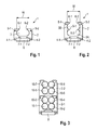
- Fig. 1 shows a possible embodiment of a stackable body 2 of a holding device 1 according to the first aspect of the present invention.
- the stackable body comprises a single recess 3 which is adapted to receive two adjacent cylindrical fiber optical components (not shown).
- the stackable body 2 shown in Fig. 1 is made of a flexible material.
- the flexible material can comprise a low flammable extruded or molded plastic material.
- the width W of the recess 3 within the stackable body 2 is twice the diameter of two adjacent cylindrical fiber optical components to be received by the recess 3. As can be seen in Fig.
- the stackable body 2 comprises capture legs 4-1, 4-2 adapted to be clipped on corresponding capture grooves of another stackable body beneath the stackable body 2 shown in Fig. 1 .
- the stackable body 2 itself also comprises capture grooves 5-1, 5-2 to which capture legs from another stackable body are clipped from above.
- two adjacent cylindrical fiber optical components can be inserted into the recess 3 through an opening of the recess. The opening is provided between two protrusions or retention brackets 6-1, 6-2, wherein the distance between the protrusions is smaller than the width W of the recess 3.
- the size of the opening is such that the cylindrical fiber optical components can be easily inserted into the recess 3 and retained after having been inserted into the recess 3. This allows for example an easy removal of the fiber optical components, for example for testing purposes.
- the capture legs 4-i as well as the corresponding capture grooves 5-1, 5-2 allow stacking of multiple stackable bodies 2 upon each other to form a holding device 1.
- the number of the stackable bodies 2 stacked upon each other in the holding device 1 can vary depending on the application.
- Each stackable body 2 comprises at a bottom side two capture legs 4-1, 4-2 facing each other and at a top side the corresponding capture grooves 5-1, 5-2. In an alternative embodiment the capture legs are at the top side and the grooves are at the bottom side of the stackable body 2.
- two parallel guiding grooves 7-1, 7-2 are provided at a bottom side of the stackable body 2 for attaching a conformable adhesive tape 8.
- the adhesive tape 8 can be a double-sided adhesive tape so that the stackable body 2 can be attached to a printed circuit board, PCB, by means of the double-sided adhesive tape 8.
- the protrusions 6-1, 6-2 of the recess 3 form retention brackets holding back the inserted fiber optical components.
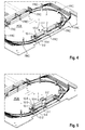
- Fig. 2 shows a further possible embodiment of a stackable body 2 of a holding device 1 according to the first aspect of the present invention.
- the stackable body 2 comprises two recesses 3a, 3b.
- the stackable body 2 comprises a lower recess 3a adapted to receive two adjacent cylindrical fiber components.
- the stackable body 2 further comprises an upper recess 3b which is adapted to receive also two adjacent cylindrical fiber components or a single cylindrical fiber component which can be pressed against the two adjacent cylindrical fiber components received by the lower recess 3a by an adhesive contact pad attached to a flexible cap clipped on the capture grooves 5-1, 5-2 of the stackable body 2.
- the stackable body 2 as illustrated in Fig.
- the stackable body 2 of the embodiment of Fig. 2 comprises in the middle between the two recesses 3a, 3b protrusions 9-1, 9-2 to hold back the inserted fiber optical components received by the lower recess 3a.
- the double-sided adhesive contact tape 8 allows to attach the stackable body 2 of Fig. 2 to a printed circuit board, PCB.
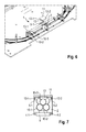
- Fig. 3 shows a cross-section view to a holding device 1 comprising two stackable bodies 2-1, 2-2.
- both stackable bodies 2-1, 2-2 are formed by stackable bodies with two recesses 3a, 3b as illustrated in Fig. 2 .
- two adjacent cylindrical fiber optical components 10-i are inserted in each recess 3a, 3b of both stackable bodies 2-1, 2-2.
- the capture legs of the upper stackable body 2-2 are clipped on the corresponding capture grooves of the lower stackable body 2-1 as illustrated in Fig. 3 .
- a double-sided adhesive contact pad or tape 8 is attached which allows to connect the holding device 1 to a printed circuit board, PCB.
- the lower stackable body 2-1 is attached to the printed circuit board, PCB, and the cylindrical fiber optical components 10-1 to 10-4 are inserted into the recesses 3a, 3b of the first stackable body 2-1.
- the upper stackable body 2-2 is clipped by means of its capture legs onto the capture grooves of the lower stackable body 2-1.
- the remaining four cylindrical fiber optical components 10-6 to 10-8 are inserted into the recesses 3a, 3b of the upper stackable body 2-2.
- the holding device 1 of Fig. 3 is adapted to receive and retain eight fiber optical components 10-1 to 10-8.
- further stackable bodies can be clipped on the upper stackable body 2-2 to increase the number of retained cylindrical fiber optical components 10-i.
- Fig. 4 shows a perspective side view on a printed circuit board, PCB, comprising a holding device 1 consisting of one stackable body 2 having two recesses 3a, 3b for receiving four cylindrical fiber optical components 10-1, 10-2, 10-3, 10-4.
- the opening of the stackable body 2 is closed by means of a flexible cap 11 clipped on the capture grooves 5-1, 5-2 of the stackable body 2.
- the stackable body 2 can be attached to the printed circuit board, PCB, by a double-side conformable adhesive tape attached to the bottom side of the stackable body 2.
- the cylindrical fiber optical components 10-i held by the holding device 1 can comprise photo detectors, micro-optic wavelength division multiplexers, MWDMs, fiber optical splices, fiber optical taps, fiber optical couplers, optical fibers or a bundle of optical fibers.
- the fiber track comprises a plurality of optical fibers which can be retained by fiber retention clips, FRC.
- Fig. 5 shows a further exemplary perspective side view on a printed circuit board, PCB, comprising a holding device 1 according to the first aspect of the present invention.
- Fig. 5 shows a holding device 1 with two stackable bodies 2-1, 2-2 stacked upon each other as shown in Fig. 3 .
- the holding device 1 comprising two stackable bodies 2-1, 2-2 which receive six cylindrical fiber optical components 10-1 to 10-6.
- it is not necessary to clip a flexible cap 11 onto the stackable body 2-2 on the top of the holding device 1.
- the lower recess 3a of the stackable body 2-2 is formed such that two adjacent cylindrical fiber optical components 10-5 to 10-6 are retained after being inserted into the respective recess.
- the lower stackable body 2-1 is attached to the printed circuit board, PCB, by means of a double-side conformable adhesive tape 8 attached to the bottom side of the stackable body 2-1 at the bottom of the respective stack.
- Fig. 6 shows a further exemplary fiber track comprising a holding device 1 according to the present invention.
- the holding device 1 comprises a single stackable body 2 having a lower recess 3a and an upper recess 3b.
- the stackable body 2 receives three cylindrical fiber optical components 10-1, 10-2, 10-3.
- the stackable body 2 having two recesses 3a, 3b can receive a maximum of four cylindrical fiber optical components 10-1 to 10-4.
- the fiber track comprises only three fiber optical components 10-1, 10-2, 10-3 which are inserted into the stackable body 2 of the holding device 1.
- a flexible cap 11 is clipped by means of capture legs 12-1, 12-2 on the capture grooves 5-1, 5-2 of the stackable body 2.
- the flexible cap 11 comprises on the lower side a small adhesive contact pad 13 to retain the third fiber optical component 10-3.
- Fig. 7 shows a cross-section view through the holding device 1 of the fiber track as illustrated in Fig. 6 .
- a single cylindrical fiber component 10-3 in the upper recess 3b of the stackable body 2 is pressed against the two adjacent cylindrical fiber components 10-1, 10-2 received by the lower recess 3a by the adhesive contact pad 13 attached to the flexible cap 11 clipped on the capture grooves 5-1, 5-2 of the stackable body 2 by means of capture legs 12-1, 12-2.
- Fig. 8 shows a further exemplary perspective view on a holding device 1 comprising a lower stackable body 2-1 and an upper stackable body 2-2.
- the lower stackable body 2-1 is adapted to receive four cylindrical fiber optical components 10-1, 10-2, 10-3, 10-4 received by the lower and upper recesses 3a, 3b of the lower stackable body 2-1.
- the upper stackable body 2-2 is clipped on the lower stackable body 2-1 and is provided to receive three fiber optical components 10-5, 10-6, 10-7, wherein the lower recess 3a receives two adjacent cylindrical fiber optical components 10-5, 10-6, and the upper recess 3b receives a single fiber optical component 10-7 retained by means of a flexible cap 11 clipped on the upper stackable body 2-2 and having at its lower side a small adhesive contact pad 13 pressing the fiber optical component 10-7 on the lower fiber optical components 10-5, 10-6.
- the holding device 1 can be used to receive an even or odd number of cylindrical fiber optical components 10-i.
- the holding device 1 is adapted to receive an even number of cylindrical fiber optical components 10-1 to 10-6. If the holding device is provided for receiving an even number of cylindrical fiber optical components 10-i it is not necessary to clip a flexible cap 11 on the capture grooves of the stackable body 2 at the top of the respective stack.
- the holding device 1 comprises two stackable bodies and receives an odd number of cylindrical fiber optical components 10-1 to 10-7.
- a flexible cap 11 is clipped on the capture grooves of the stackable body 2-2 at the top of the respective stack to retain the cylindrical fiber optical component 10-7. Since the number of stackable bodies 2-i can vary, the number of retained cylindrical fiber optical components 10-i can also vary depending on the respective application.
- the holding device 1 allows for a minimal board space footprint of the holding device 1.
- the footprint of the base stackable body 2-1 at the bottom of the stack requires a minimal space on the printed circuit board, PCB.
- the stackability of a plurality of stackable bodies 2-i allows for a great capacity to receive a plurality of cylindrical fiber optical components 10-i requiring a minimum of board space of the printed circuit board, PCB.
- the cylindrical fiber optical components 10-i can be easily removed for testing or replaced by other cylindrical components.
- the stackable bodies 2-i each having recesses 3 of different widths w for different cylindrical fiber optical components.
- This allows to hold cylindrical components of varying diameter.
- the stackable bodies 2-i with the same or different size of the recesses 3 can be clipped on each other in a modular system. Accordingly, an operator or user can attach a high number of different cylindrical optical components 10-i on a printed circuit board, PCB, without getting confused so that connection errors are minimized.
- the cylindrical components can comprise for instance a diameter of 3mm. This allows for a narrow profile of the retention brackets 6-1, 6-2 of the stackable body 2.
Landscapes
- Physics & Mathematics (AREA)
- General Physics & Mathematics (AREA)
- Optics & Photonics (AREA)
- Engineering & Computer Science (AREA)
- Manufacturing & Machinery (AREA)
- Microelectronics & Electronic Packaging (AREA)
- Optical Couplings Of Light Guides (AREA)
- Light Guides In General And Applications Therefor (AREA)
Abstract
Description
- The invention relates to a holding device for holding cylindrical fiber optic components of a fiber track on a printed circuit board.
- A fiber track on a printed circuit board can comprise different cylindrical fiber optical components which are assembled on a printed circuit board. The cylindrical fiber optical components can comprise for instance photo detectors, fiber optical splices, fiber optical couplers, fiber optical taps, micro-optic wavelength division multiplexers and optical fibers or a bundle of optical fibers.
- On a conventional printed circuit board, these different kinds of cylindrical fiber optical components are glued together or spread out on the printed circuit using conventional fiber component holder clips. When gluing different fiber optical components together, this has the severe drawback that a single fiber optical component cannot be separated again or replaced by another fiber optical component. Spreading out the different fiber components on the printed circuit board has the disadvantage that a lot of space is occupied on the printed circuit board. Furthermore, the fiber track assembly can become very confusing to the user leading to connection errors between the different fiber optical components.
- Accordingly, there is a need for a holding device which allows easy attachment and removal of fiber optical components and which requires a minimal space on a printed circuit board.
- The invention provides according to a first aspect a holding device for holding cylindrical fiber optical components comprising at least one stackable body each having at least one recess adapted to receive cylindrical fiber optical components.
- According to a possible embodiment of the holding device, the stackable body comprises a single recess adapted to receive two adjacent cylindrical fiber optical components.
- According to a further possible embodiment of the holding device, the stackable body comprises
a lower recess adapted to receive two adjacent cylindrical fiber components and
an upper recess adapted to receive two adjacent cylindrical fiber components or a single cylindrical fiber component pressed against the two adjacent cylindrical fiber components received by the lower recess by an adhesive contact pad attached to a flexible cap clipped on capture grooves of the stackable body. - According to a further possible embodiment of the holding device according to the first aspect of the present invention, the stackable body comprises capture legs adapted to be clipped on corresponding capture grooves of another stackable body.
- According to a further possible embodiment of the holding device according to the first aspect of the present invention, a width of the recess within the stackable body is twice the diameter of a cylindrical fiber optical component.
- In a still further possible embodiment of the holding device according to the first aspect of the present invention, the stackable body comprises at a bottom side two capture legs facing each other and at a top side corresponding capture grooves.
- In a further possible embodiment of the holding device according to the first aspect of the present invention, the holding device comprises two parallel guiding grooves at the bottom side of the stackable body for attaching a conformable adhesive tape.
- In a still further possible embodiment of the holding device according to the first aspect of the present invention, a flexible cap is clipped on capture grooves of the stackable body at the top of the respective stack.
- In a still further possible embodiment of the holding device according to the first aspect of the present invention, the lowest stackable body is attached to a printed circuit board by means of a double-side conformable adhesive tape attached to the bottom side of the stackable body at the bottom of the respective stack.
- In a still further possible embodiment of the holding device according to the first aspect of the present invention, the lowest stackable body of the respective stack is attached to a printed circuit board by attachment means.
- In a still further possible embodiment of the holding device according to the first aspect of the present invention, the stackable body is made of a flexible material.
- In a still further possible embodiment of the holding device according to the first aspect of the present invention, the flexible material is a low flammable extruded or molded plastic material.
- The invention further provides according to a second aspect a fiber track of a printed circuit board comprising at least one holding device according to the first aspect of the present invention.
- In a possible embodiment of the fiber track according to the second aspect of the present invention, the cylindrical fiber optical components held by the holding device comprise photo detectors, micro-optic wavelength division multiplexers, MWDMs, fiber optical splices, fiber optical taps, fiber optical couplers, optical fibers and/or a bundle of optical fibers.
- In the following, possible embodiments of the different aspects of the present invention are described in more detail with reference to the enclosed figures.
- Fig. 1
- shows a cross-section view through a possible embodiment of a stackable body used in a holding device according to the first aspect of the present invention;
- Fig. 2
- shows a cross-section view through an alternative embodiment of a stackable body used in a holding device according to the first aspect of the present invention;
- Fig. 3
- shows an exemplary holding device comprising two stackable bodies according to the first aspect of the present invention;
- Fig. 4
- shows a perspective view on an exemplary fiber track comprising a holding device according to the present invention;
- Fig. 5
- shows an exemplary side view on a fiber track when mounting an exemplary holding device according to the present invention on a printed circuit board;
- Fig. 6
- shows a perspective side view for illustrating the mounting of an exemplary holding device according to the present invention on a printed circuit board;
- Fig. 7
- shows a cross-section view through a stackable body of an exemplary holding device according to the first aspect of the present invention;
- Fig. 8
- shows a perspective view on an exemplary holding device comprising two stackable bodies according to the present invention.
- The invention provides according to a first aspect a
holding device 1 for holding cylindrical fiber optical components comprising at least onestackable body 2. Theholding device 1 according to the present invention comprises one or morestackable bodies 2 each having at least one recess 3 adapted to receive cylindrical fiber optical components. The cylindrical fiber optical components held by theholding device 1 can comprise in possible embodiments photo detectors, fiber optical splices, fiber optical taps, fiber optical couplers, micro-optic wavelength division multiplexers, optical fibers or even bundles of optical fibers. Eachstackable body 2 has at least one recess 3 adapted to receive cylindrical fiber optical components. -
Fig. 1 shows a possible embodiment of astackable body 2 of aholding device 1 according to the first aspect of the present invention. In the shown exemplary embodiment, the stackable body comprises a single recess 3 which is adapted to receive two adjacent cylindrical fiber optical components (not shown). Thestackable body 2 shown inFig. 1 is made of a flexible material. The flexible material can comprise a low flammable extruded or molded plastic material. In the embodiment shown inFig. 1 , the width W of the recess 3 within thestackable body 2 is twice the diameter of two adjacent cylindrical fiber optical components to be received by the recess 3. As can be seen inFig. 1 , thestackable body 2 comprises capture legs 4-1, 4-2 adapted to be clipped on corresponding capture grooves of another stackable body beneath thestackable body 2 shown inFig. 1 . Thestackable body 2 itself also comprises capture grooves 5-1, 5-2 to which capture legs from another stackable body are clipped from above. In the embodiment shown inFig. 1 , two adjacent cylindrical fiber optical components can be inserted into the recess 3 through an opening of the recess. The opening is provided between two protrusions or retention brackets 6-1, 6-2, wherein the distance between the protrusions is smaller than the width W of the recess 3. The size of the opening is such that the cylindrical fiber optical components can be easily inserted into the recess 3 and retained after having been inserted into the recess 3. This allows for example an easy removal of the fiber optical components, for example for testing purposes. The capture legs 4-i as well as the corresponding capture grooves 5-1, 5-2 allow stacking of multiplestackable bodies 2 upon each other to form aholding device 1. The number of thestackable bodies 2 stacked upon each other in theholding device 1 can vary depending on the application. Eachstackable body 2 comprises at a bottom side two capture legs 4-1, 4-2 facing each other and at a top side the corresponding capture grooves 5-1, 5-2. In an alternative embodiment the capture legs are at the top side and the grooves are at the bottom side of thestackable body 2. - In a possible embodiment as shown in
Fig. 1 ., two parallel guiding grooves 7-1, 7-2 are provided at a bottom side of thestackable body 2 for attaching a conformableadhesive tape 8. Theadhesive tape 8 can be a double-sided adhesive tape so that thestackable body 2 can be attached to a printed circuit board, PCB, by means of the double-sidedadhesive tape 8. The protrusions 6-1, 6-2 of the recess 3 form retention brackets holding back the inserted fiber optical components. -
Fig. 2 shows a further possible embodiment of astackable body 2 of aholding device 1 according to the first aspect of the present invention. In the shown embodiment, thestackable body 2 comprises two recesses 3a, 3b. Thestackable body 2 comprises a lower recess 3a adapted to receive two adjacent cylindrical fiber components. Thestackable body 2 further comprises an upper recess 3b which is adapted to receive also two adjacent cylindrical fiber components or a single cylindrical fiber component which can be pressed against the two adjacent cylindrical fiber components received by the lower recess 3a by an adhesive contact pad attached to a flexible cap clipped on the capture grooves 5-1, 5-2 of thestackable body 2. Thestackable body 2 as illustrated inFig. 2 also comprises two capture legs 4-1, 4-2 facing each other and at a top side corresponding capture grooves 5-1, 5-2. The width W of the recesses 3a, 3b corresponds to twice the diameter of a cylindrical fiber optical component. The upper recess 3b comprises an opening for inserting the fiber optical components through an opening between two protrusions or retention brackets 6-1, 6-2. Thestackable body 2 of the embodiment ofFig. 2 comprises in the middle between the two recesses 3a, 3b protrusions 9-1, 9-2 to hold back the inserted fiber optical components received by the lower recess 3a. Thestackable body 2 ofFig. 2 can also comprise two parallel guiding grooves 7-1, 7-2 at the bottom side of thestackable body 2 for attaching a conformableadhesive tape 8. The double-sidedadhesive contact tape 8 allows to attach thestackable body 2 ofFig. 2 to a printed circuit board, PCB. -
Fig. 3 shows a cross-section view to aholding device 1 comprising two stackable bodies 2-1, 2-2. In the shown exemplary embodiment of the holdingdevice 1, both stackable bodies 2-1, 2-2 are formed by stackable bodies with two recesses 3a, 3b as illustrated inFig. 2 . In each recess 3a, 3b of both stackable bodies 2-1, 2-2, two adjacent cylindrical fiber optical components 10-i are inserted. The capture legs of the upper stackable body 2-2 are clipped on the corresponding capture grooves of the lower stackable body 2-1 as illustrated inFig. 3 . At the lower stackable body 2-1, a double-sided adhesive contact pad ortape 8 is attached which allows to connect theholding device 1 to a printed circuit board, PCB. In the exemplary embodiment ofFig. 1 , first, the lower stackable body 2-1 is attached to the printed circuit board, PCB, and the cylindrical fiber optical components 10-1 to 10-4 are inserted into the recesses 3a, 3b of the first stackable body 2-1. After having inserted the fiber optical component 10-1 to 10-4 into the lower stackable body 2-1, the upper stackable body 2-2 is clipped by means of its capture legs onto the capture grooves of the lower stackable body 2-1. After that, the remaining four cylindrical fiber optical components 10-6 to 10-8 are inserted into the recesses 3a, 3b of the upper stackable body 2-2. In the exemplary embodiment ofFig. 1 , the holdingdevice 1 ofFig. 3 is adapted to receive and retain eight fiber optical components 10-1 to 10-8. In the exemplary embodiment ofFig. 3 , further stackable bodies can be clipped on the upper stackable body 2-2 to increase the number of retained cylindrical fiber optical components 10-i. -
Fig. 4 shows a perspective side view on a printed circuit board, PCB, comprising aholding device 1 consisting of onestackable body 2 having two recesses 3a, 3b for receiving four cylindrical fiber optical components 10-1, 10-2, 10-3, 10-4. In the shown exemplary embodiment, the opening of thestackable body 2 is closed by means of aflexible cap 11 clipped on the capture grooves 5-1, 5-2 of thestackable body 2. Thestackable body 2 can be attached to the printed circuit board, PCB, by a double-side conformable adhesive tape attached to the bottom side of thestackable body 2. The cylindrical fiber optical components 10-i held by the holdingdevice 1 can comprise photo detectors, micro-optic wavelength division multiplexers, MWDMs, fiber optical splices, fiber optical taps, fiber optical couplers, optical fibers or a bundle of optical fibers. The fiber track comprises a plurality of optical fibers which can be retained by fiber retention clips, FRC. -
Fig. 5 shows a further exemplary perspective side view on a printed circuit board, PCB, comprising aholding device 1 according to the first aspect of the present invention.Fig. 5 shows aholding device 1 with two stackable bodies 2-1, 2-2 stacked upon each other as shown inFig. 3 . In the shown exemplary embodiment, the holdingdevice 1 comprising two stackable bodies 2-1, 2-2 which receive six cylindrical fiber optical components 10-1 to 10-6. As can be seen inFig. 5 , it is not necessary to clip aflexible cap 11 onto the stackable body 2-2 on the top of the holdingdevice 1. This is because the lower recess 3a of the stackable body 2-2 is formed such that two adjacent cylindrical fiber optical components 10-5 to 10-6 are retained after being inserted into the respective recess. The lower stackable body 2-1 is attached to the printed circuit board, PCB, by means of a double-side conformableadhesive tape 8 attached to the bottom side of the stackable body 2-1 at the bottom of the respective stack. -
Fig. 6 shows a further exemplary fiber track comprising aholding device 1 according to the present invention. In this exemplary embodiment, the holdingdevice 1 comprises a singlestackable body 2 having a lower recess 3a and an upper recess 3b. In the embodiment ofFig. 6 , thestackable body 2 receives three cylindrical fiber optical components 10-1, 10-2, 10-3. Thestackable body 2 having two recesses 3a, 3b can receive a maximum of four cylindrical fiber optical components 10-1 to 10-4. In the exemplary embodiment ofFig. 6 , the fiber track comprises only three fiber optical components 10-1, 10-2, 10-3 which are inserted into thestackable body 2 of the holdingdevice 1. Since the upper recess 3b of thestackable body 2 receives in the shown exemplary embodiment not two adjacent cylindrical fiber optical components but a single fiber optical component 10-3, aflexible cap 11 is clipped by means of capture legs 12-1, 12-2 on the capture grooves 5-1, 5-2 of thestackable body 2. As can be seen inFig. 6 , theflexible cap 11 comprises on the lower side a smalladhesive contact pad 13 to retain the third fiber optical component 10-3. -
Fig. 7 shows a cross-section view through the holdingdevice 1 of the fiber track as illustrated inFig. 6 . As can be seen inFig. 7 , a single cylindrical fiber component 10-3 in the upper recess 3b of thestackable body 2 is pressed against the two adjacent cylindrical fiber components 10-1, 10-2 received by the lower recess 3a by theadhesive contact pad 13 attached to theflexible cap 11 clipped on the capture grooves 5-1, 5-2 of thestackable body 2 by means of capture legs 12-1, 12-2. -
Fig. 8 shows a further exemplary perspective view on aholding device 1 comprising a lower stackable body 2-1 and an upper stackable body 2-2. In the exemplary embodiment ofFig. 8 , the lower stackable body 2-1 is adapted to receive four cylindrical fiber optical components 10-1, 10-2, 10-3, 10-4 received by the lower and upper recesses 3a, 3b of the lower stackable body 2-1. The upper stackable body 2-2 is clipped on the lower stackable body 2-1 and is provided to receive three fiber optical components 10-5, 10-6, 10-7, wherein the lower recess 3a receives two adjacent cylindrical fiber optical components 10-5, 10-6, and the upper recess 3b receives a single fiber optical component 10-7 retained by means of aflexible cap 11 clipped on the upper stackable body 2-2 and having at its lower side a smalladhesive contact pad 13 pressing the fiber optical component 10-7 on the lower fiber optical components 10-5, 10-6. - Accordingly, the holding
device 1 according to the present invention can be used to receive an even or odd number of cylindrical fiber optical components 10-i. For example, in the embodiment shown inFig. 5 , the holdingdevice 1 is adapted to receive an even number of cylindrical fiber optical components 10-1 to 10-6. If the holding device is provided for receiving an even number of cylindrical fiber optical components 10-i it is not necessary to clip aflexible cap 11 on the capture grooves of thestackable body 2 at the top of the respective stack. - In contrast, in the embodiment as illustrated for instance in
Fig. 8 , the holdingdevice 1 comprises two stackable bodies and receives an odd number of cylindrical fiber optical components 10-1 to 10-7. In this embodiment, aflexible cap 11 is clipped on the capture grooves of the stackable body 2-2 at the top of the respective stack to retain the cylindrical fiber optical component 10-7. Since the number of stackable bodies 2-i can vary, the number of retained cylindrical fiber optical components 10-i can also vary depending on the respective application. - The holding
device 1 according to the present invention allows for a minimal board space footprint of the holdingdevice 1. The footprint of the base stackable body 2-1 at the bottom of the stack requires a minimal space on the printed circuit board, PCB. The stackability of a plurality of stackable bodies 2-i allows for a great capacity to receive a plurality of cylindrical fiber optical components 10-i requiring a minimum of board space of the printed circuit board, PCB. Moreover, with the holdingdevice 1 according to the present invention, the cylindrical fiber optical components 10-i can be easily removed for testing or replaced by other cylindrical components. - It is possible to use in a holding device different kinds of stackable bodies 2-i each having recesses 3 of different widths w for different cylindrical fiber optical components. This allows to hold cylindrical components of varying diameter. In a possible embodiment, the stackable bodies 2-i with the same or different size of the recesses 3 can be clipped on each other in a modular system. Accordingly, an operator or user can attach a high number of different cylindrical optical components 10-i on a printed circuit board, PCB, without getting confused so that connection errors are minimized. In a possible embodiment, the cylindrical components can comprise for instance a diameter of 3mm. This allows for a narrow profile of the retention brackets 6-1, 6-2 of the
stackable body 2.
Claims (14)
- A holding device (1) for holding cylindrical fiber optical components comprising at least one stackable body (2) each having at least one recess (3) adapted to receive cylindrical fiber optical components (10-i).
- The holding device according to claim 1,
wherein the stackable body (2) comprises a single recess (3) adapted to receive two adjacent cylindrical fiber optical components (10-i). - The holding device according to claim 1,
wherein the stackable body (2) comprises
a lower recess (3A) adapted to receive two adjacent cylindrical fiber components and
an upper recess (3B) adapted to receive two adjacent cylindrical fiber components or a single cylindrical fiber component pressed against the two adjacent cylindrical fiber components received by the lower recess (3A) by an adhesive contact pad (13) attached to a flexible cap (11) clipped on capture grooves (5-1, 5-2) of the stackable body (2). - The holding device according to any of the preceding claims 1 to 3,
wherein the stackable body (2) comprises capture legs (4-1, 4-2) adapted to be clipped on corresponding capture grooves (5-1, 5-2) of another stackable body (2). - The holding device according to any of the preceding claims 1 to 4,
wherein a width of the recess (3; 3A, 3B) within said stackable body (2) is twice the diameter of a cylindrical fiber optical component (10-i). - The holding device according to claim 1,
wherein the stackable body (2) comprises at a bottom side two capture legs (4-1, 4-2) facing each other and at a top side corresponding capture grooves (5-1, 5-2). - The holding device according to claim 6,
wherein two parallel guiding grooves (7-1, 7-2) are provided at the bottom side of said stackable body (2) for attaching a conformable adhesive tape (8). - The holding device according to claim 6,
wherein a flexible cap (11) is clipped on capture grooves (5-1, 5-2) of the stackable body (2) at the top of the respective stack. - The holding device according to claim 6,
wherein the lowest stackable body (2) is attached to a printed circuit board (PCB) by means of a double-side conformable adhesive tape (8) attached to the bottom side of the stackable body (2) at the bottom of the respective stack. - The holding device according to claim 6,
wherein a lowest stackable body (2) of the respective stack is attached to a printed circuit board (PCB) by attachment means. - The holding device according to any of the preceding claims 1 to 10,
wherein the stackable body (2) is made of a flexible material. - The holding device according to claim 11,
wherein the flexible material is a low flammable extruded or molded plastic material. - A fiber track of a printed circuit board (PCB) comprising at least one holding device (1) according to any of the preceding claims 1 to 12.
- The fiber track according to claim 13,
wherein the cylindrical fiber optical components (10-i) held by said holding device (1) comprise photo detectors, micro-optic wavelength division multiplexers, MWDMs, fiber optical splices, fiber optical taps, fiber optical couplers, optical fibers and/or a bundle of optical fibers.
Applications Claiming Priority (1)
| Application Number | Priority Date | Filing Date | Title |
|---|---|---|---|
| US14/032,275 US10061089B2 (en) | 2013-09-20 | 2013-09-20 | Fiber optic component holding device for fibers in side-by-side contact |
Publications (2)
| Publication Number | Publication Date |
|---|---|
| EP2851724A1 true EP2851724A1 (en) | 2015-03-25 |
| EP2851724B1 EP2851724B1 (en) | 2018-02-28 |
Family
ID=49518876
Family Applications (1)
| Application Number | Title | Priority Date | Filing Date |
|---|---|---|---|
| EP13192017.5A Active EP2851724B1 (en) | 2013-09-20 | 2013-11-07 | A fiber optic component holding device |
Country Status (2)
| Country | Link |
|---|---|
| US (1) | US10061089B2 (en) |
| EP (1) | EP2851724B1 (en) |
Cited By (1)
| Publication number | Priority date | Publication date | Assignee | Title |
|---|---|---|---|---|
| CN112823576A (en) * | 2018-09-04 | 2021-05-18 | 捷普有限公司 | Apparatus, system and method for providing a tray for holding optoelectronic devices during printed circuit board manufacturing |
Families Citing this family (4)
| Publication number | Priority date | Publication date | Assignee | Title |
|---|---|---|---|---|
| US10845561B1 (en) * | 2019-06-28 | 2020-11-24 | Afl Telecommunications Llc | Fiber optic cassettes and splice modules |
| US11269148B2 (en) * | 2020-04-28 | 2022-03-08 | Ii-Vi Delaware, Inc. | Organizer for fiber optic components |
| CN116261534B (en) * | 2020-10-22 | 2026-05-01 | 住友电装株式会社 | Composite wire harness |
| US11700704B2 (en) * | 2021-04-30 | 2023-07-11 | Quanta Computer Inc. | Adjustable air blocks for cable routing |
Citations (5)
| Publication number | Priority date | Publication date | Assignee | Title |
|---|---|---|---|---|
| US5146532A (en) * | 1990-11-20 | 1992-09-08 | Scientific-Atlanta, Inc. | Optical fiber retention device |
| WO1996038752A1 (en) * | 1995-05-30 | 1996-12-05 | The Whitaker Corporation | Optical fiber splice holder and strain relief |
| WO1998037447A1 (en) * | 1997-02-18 | 1998-08-27 | Integrated Optical Components Limited | Carriers for optical components and methods of using the same |
| WO2007024912A1 (en) * | 2005-08-25 | 2007-03-01 | Adc Telecommunications, Inc. | Stackable splice chip device |
| US20100111481A1 (en) * | 2008-11-06 | 2010-05-06 | Furukawa Electric North America, Inc., | System for securing fiber optic devices in management trays |
Family Cites Families (51)
| Publication number | Priority date | Publication date | Assignee | Title |
|---|---|---|---|---|
| JPS5813190Y2 (en) * | 1979-01-23 | 1983-03-14 | 北川工業株式会社 | flat cable holder |
| US4635886A (en) * | 1985-10-18 | 1987-01-13 | Dek, Inc. | Flat wire clip |
| DE3622164A1 (en) * | 1986-07-02 | 1988-01-14 | Minnesota Mining & Mfg | HOLDING DEVICE FOR CONNECTING WIRE ON AN ELECTRICAL CONNECTOR |
| DE4415218C1 (en) * | 1994-04-26 | 1995-10-19 | Krone Ag | Housing for optical components |
| US5625737A (en) * | 1995-12-11 | 1997-04-29 | Lucent Technologies Inc. | Optical fiber holder and method using same |
| US5715348A (en) * | 1996-03-27 | 1998-02-03 | Next Level Communications | Fiber management system and method for routing optical fiber having a minimum bend radius |
| US5893539A (en) * | 1997-09-25 | 1999-04-13 | Ncr Corporation | Cable management system |
| US5921402A (en) * | 1998-04-27 | 1999-07-13 | Systems Manufacturing Corporation | Cable management track system |
| JP2000075145A (en) * | 1998-09-01 | 2000-03-14 | Fujitsu Ltd | Optical fiber holder |
| US6354543B1 (en) * | 1999-01-12 | 2002-03-12 | Andrew Corporation | Stackable transmission line hanger |
| US6285815B1 (en) * | 1999-09-07 | 2001-09-04 | Lucent Technologies Inc. | High density fusion splice holder |
| US6249636B1 (en) * | 1999-09-07 | 2001-06-19 | Lucent Technologies, Inc. | High density fusion splice holder |
| US6249635B1 (en) * | 1999-09-07 | 2001-06-19 | Lucent Technologies, Inc. | Universal fiber optic splice holder |
| US6259851B1 (en) * | 1999-09-17 | 2001-07-10 | Lucent Technologies Inc. | High density fiber splice holder |
| US6456772B1 (en) * | 1999-09-21 | 2002-09-24 | Avaya Technology Corp. | System for removable attachment of two objects |
| DE10003636A1 (en) * | 2000-01-28 | 2001-08-02 | Rxs Schrumpftech Garnituren | Sleeve insert for sleeve for feeding light waveguide elements, has profile body with main chamber and three lateral guide chambers for light waveguide elements |
| WO2001079645A1 (en) * | 2000-04-14 | 2001-10-25 | Ren Judkins | Headrail for double shade |
| US6687450B1 (en) * | 2000-05-15 | 2004-02-03 | Tyco Electronics Raychem Nv | Break-out device |
| US6421494B1 (en) * | 2000-11-29 | 2002-07-16 | Corning Cable Systems Llc | Drop cable strain relief |
| FR2821934B1 (en) * | 2001-03-12 | 2004-06-25 | Teem Photonics | PASSAGE GUIDE FOR OPTICAL FIBERS AND OPTICAL COMPONENT RECEIVING BOX PROVIDED WITH SUCH A GUIDE |
| US6768858B2 (en) * | 2001-03-16 | 2004-07-27 | Adc Telecommunications, Inc. | Cable clip with segregator and method |
| US6539161B2 (en) * | 2001-03-16 | 2003-03-25 | Adc Telecommunications, Inc. | Cable routing clip |
| US6512876B2 (en) * | 2001-04-25 | 2003-01-28 | Lucent Technologies Inc. | Fiber splice tray |
| US6567601B2 (en) * | 2001-06-19 | 2003-05-20 | Lucent Technologies Inc. | Fiber-optic cable routing and management system and components |
| US6603918B2 (en) * | 2001-06-25 | 2003-08-05 | Lucent Technologies Inc. | Fiber-optic cable routing and bend limiting device |
| TW505221U (en) * | 2001-10-12 | 2002-10-01 | Hon Hai Prec Ind Co Ltd | Fastening apparatus for optical fiber |
| US6671447B1 (en) * | 2001-11-02 | 2003-12-30 | Ciena Corporation | Optical fiber organizer for organizing optical fiber inside of a fiber duct |
| US6661962B1 (en) * | 2001-11-15 | 2003-12-09 | Siwave, Inc. | Optical element support structure and methods of using and making the same |
| TW489978U (en) * | 2001-11-15 | 2002-06-01 | Hon Hai Prec Ind Co Ltd | Retaining device for optical fiber |
| JP2003156634A (en) * | 2001-11-19 | 2003-05-30 | Fujitsu Ltd | Optical fiber holder |
| US6801704B1 (en) * | 2003-05-30 | 2004-10-05 | Lucent Technologies Inc. | Fiber optics splice holder |
| US7318567B2 (en) * | 2005-03-07 | 2008-01-15 | Belkin International, Inc. | Cable management device |
| US7272291B2 (en) * | 2005-08-25 | 2007-09-18 | Adc Telecommunications, Inc. | Splice chip device |
| US7514631B2 (en) * | 2005-10-17 | 2009-04-07 | Hewlett-Packard Development Company, L.P. | System and method for managing cables in a display base |
| US7228048B1 (en) * | 2006-03-20 | 2007-06-05 | Dade Behring Inc. | Liquid tube and electrical cable clamp with locking features |
| DE102006034236B3 (en) * | 2006-07-25 | 2008-05-15 | Airbus Deutschland Gmbh | Holder for optical fibers |
| EP2074459A1 (en) * | 2006-10-16 | 2009-07-01 | 3M Innovative Properties Company | Splice holder device |
| US7418186B1 (en) * | 2007-05-11 | 2008-08-26 | Preformed Line Products Company | Fiber retention sleeve |
| US7523898B1 (en) * | 2008-01-31 | 2009-04-28 | Sony Corporation | Wire holder with single step installation into T-shaped hole in support substrate |
| US8290330B2 (en) * | 2008-09-05 | 2012-10-16 | Adc Gmbh | Patch panel assembly |
| US7734139B2 (en) * | 2008-10-07 | 2010-06-08 | Cisco Technology, Inc. | Modular cable-management system |
| DE102008055823A1 (en) * | 2008-11-04 | 2010-05-06 | Mulzer, Stephan, Dr. | holder |
| US8331754B2 (en) * | 2009-09-23 | 2012-12-11 | Corning Cable Systems Llc | Strain relief device and method for fiber optic cables |
| US8824850B2 (en) * | 2010-01-26 | 2014-09-02 | Adc Telecommunications, Inc. | Insect-infestation prevention device for a telecommunications equipment housing |
| US8879881B2 (en) * | 2010-04-30 | 2014-11-04 | Corning Cable Systems Llc | Rotatable routing guide and assembly |
| US8254742B2 (en) * | 2010-05-11 | 2012-08-28 | Commscope, Inc. Of North Carolina | Splice holder |
| US8109783B2 (en) * | 2010-06-30 | 2012-02-07 | Avx Corporation | Insulation displacement connector (IDC) |
| GB201101469D0 (en) * | 2011-01-28 | 2011-03-16 | Airbus Operations Ltd | Cable raceway |
| US8770532B2 (en) * | 2011-05-13 | 2014-07-08 | Commscope, Inc. Of North Carolina | Cable retaining ring having slide closure and cable support tray including the cable retaining ring |
| US8559784B2 (en) * | 2011-10-26 | 2013-10-15 | All Systems Broadband, Inc. | Modular assembly for supporting fiber optic splices |
| TW201403158A (en) * | 2012-07-13 | 2014-01-16 | Gloriole Electroptic Technology Corp | Optical fiber line organizing device |
-
2013
- 2013-09-20 US US14/032,275 patent/US10061089B2/en active Active
- 2013-11-07 EP EP13192017.5A patent/EP2851724B1/en active Active
Patent Citations (5)
| Publication number | Priority date | Publication date | Assignee | Title |
|---|---|---|---|---|
| US5146532A (en) * | 1990-11-20 | 1992-09-08 | Scientific-Atlanta, Inc. | Optical fiber retention device |
| WO1996038752A1 (en) * | 1995-05-30 | 1996-12-05 | The Whitaker Corporation | Optical fiber splice holder and strain relief |
| WO1998037447A1 (en) * | 1997-02-18 | 1998-08-27 | Integrated Optical Components Limited | Carriers for optical components and methods of using the same |
| WO2007024912A1 (en) * | 2005-08-25 | 2007-03-01 | Adc Telecommunications, Inc. | Stackable splice chip device |
| US20100111481A1 (en) * | 2008-11-06 | 2010-05-06 | Furukawa Electric North America, Inc., | System for securing fiber optic devices in management trays |
Cited By (2)
| Publication number | Priority date | Publication date | Assignee | Title |
|---|---|---|---|---|
| CN112823576A (en) * | 2018-09-04 | 2021-05-18 | 捷普有限公司 | Apparatus, system and method for providing a tray for holding optoelectronic devices during printed circuit board manufacturing |
| US12228771B2 (en) | 2018-09-04 | 2025-02-18 | Jabil Inc. | Apparatus, system, and method of providing a tray for holding an optoelectronic device during printed circuit board manufacturing |
Also Published As
| Publication number | Publication date |
|---|---|
| US20150086170A1 (en) | 2015-03-26 |
| EP2851724B1 (en) | 2018-02-28 |
| US10061089B2 (en) | 2018-08-28 |
Similar Documents
| Publication | Publication Date | Title |
|---|---|---|
| EP2851724B1 (en) | A fiber optic component holding device | |
| US11714246B2 (en) | Optical assemblies with contoured base | |
| CN106687840B (en) | Tools and methods for fabricating fiber optic arrays | |
| US10203466B2 (en) | Pivotable cover for sliding tray and sliding tray including the cover | |
| US9575278B2 (en) | Splice holder | |
| US20160231524A1 (en) | Bridging connector for adjacent sliding trays | |
| US8165442B2 (en) | System for securing fiber optic devices in management trays | |
| US8770532B2 (en) | Cable retaining ring having slide closure and cable support tray including the cable retaining ring | |
| EP4024108B1 (en) | Cable management arrangement | |
| UA70916C2 (en) | Device for layout of optical fibres | |
| US9478883B2 (en) | Card connector | |
| US7515806B2 (en) | Fiber optic cable guide | |
| KR20150053751A (en) | Cable management system including splitter/filter tray | |
| JPH05503165A (en) | card cage | |
| ATE528677T1 (en) | STACKABLE SPLICING CHIP DEVICE | |
| CN104860009A (en) | Snap-in Pusher | |
| US20210333480A1 (en) | Apparatus and method for arraying optical fibers side by side on a pitch greater than the diameter of the fiber | |
| US20080206112A1 (en) | Modular test tube holder | |
| KR20010113649A (en) | Ganged boxes for holding optical components | |
| JP2005503575A (en) | Optical ferrule having multiple rows of multiple optical fibers | |
| SE504587C2 (en) | Fanout device and method of manufacture thereof | |
| EP2075624A3 (en) | Optical sheet and display device having the same | |
| JPS60140206A (en) | Retainer for packaged fiber optic splices | |
| JP5072610B2 (en) | Optical connector cover and optical wiring board using optical connector cover | |
| DE60133855D1 (en) | Computing device |
Legal Events
| Date | Code | Title | Description |
|---|---|---|---|
| PUAI | Public reference made under article 153(3) epc to a published international application that has entered the european phase |
Free format text: ORIGINAL CODE: 0009012 |
|
| 17P | Request for examination filed |
Effective date: 20140611 |
|
| AK | Designated contracting states |
Kind code of ref document: A1 Designated state(s): AL AT BE BG CH CY CZ DE DK EE ES FI FR GB GR HR HU IE IS IT LI LT LU LV MC MK MT NL NO PL PT RO RS SE SI SK SM TR |
|
| AX | Request for extension of the european patent |
Extension state: BA ME |
|
| 17Q | First examination report despatched |
Effective date: 20161010 |
|
| STAA | Information on the status of an ep patent application or granted ep patent |
Free format text: STATUS: EXAMINATION IS IN PROGRESS |
|
| GRAP | Despatch of communication of intention to grant a patent |
Free format text: ORIGINAL CODE: EPIDOSNIGR1 |
|
| STAA | Information on the status of an ep patent application or granted ep patent |
Free format text: STATUS: GRANT OF PATENT IS INTENDED |
|
| INTG | Intention to grant announced |
Effective date: 20170927 |
|
| GRAS | Grant fee paid |
Free format text: ORIGINAL CODE: EPIDOSNIGR3 |
|
| GRAA | (expected) grant |
Free format text: ORIGINAL CODE: 0009210 |
|
| STAA | Information on the status of an ep patent application or granted ep patent |
Free format text: STATUS: THE PATENT HAS BEEN GRANTED |
|
| AK | Designated contracting states |
Kind code of ref document: B1 Designated state(s): AL AT BE BG CH CY CZ DE DK EE ES FI FR GB GR HR HU IE IS IT LI LT LU LV MC MK MT NL NO PL PT RO RS SE SI SK SM TR |
|
| REG | Reference to a national code |
Ref country code: GB Ref legal event code: FG4D Ref country code: CH Ref legal event code: EP |
|
| REG | Reference to a national code |
Ref country code: AT Ref legal event code: REF Ref document number: 974758 Country of ref document: AT Kind code of ref document: T Effective date: 20180315 |
|
| REG | Reference to a national code |
Ref country code: IE Ref legal event code: FG4D |
|
| REG | Reference to a national code |
Ref country code: DE Ref legal event code: R096 Ref document number: 602013033649 Country of ref document: DE |
|
| REG | Reference to a national code |
Ref country code: NL Ref legal event code: MP Effective date: 20180228 |
|
| REG | Reference to a national code |
Ref country code: LT Ref legal event code: MG4D |
|
| REG | Reference to a national code |
Ref country code: AT Ref legal event code: MK05 Ref document number: 974758 Country of ref document: AT Kind code of ref document: T Effective date: 20180228 |
|
| PG25 | Lapsed in a contracting state [announced via postgrant information from national office to epo] |
Ref country code: ES Free format text: LAPSE BECAUSE OF FAILURE TO SUBMIT A TRANSLATION OF THE DESCRIPTION OR TO PAY THE FEE WITHIN THE PRESCRIBED TIME-LIMIT Effective date: 20180228 Ref country code: HR Free format text: LAPSE BECAUSE OF FAILURE TO SUBMIT A TRANSLATION OF THE DESCRIPTION OR TO PAY THE FEE WITHIN THE PRESCRIBED TIME-LIMIT Effective date: 20180228 Ref country code: CY Free format text: LAPSE BECAUSE OF FAILURE TO SUBMIT A TRANSLATION OF THE DESCRIPTION OR TO PAY THE FEE WITHIN THE PRESCRIBED TIME-LIMIT Effective date: 20180228 Ref country code: LT Free format text: LAPSE BECAUSE OF FAILURE TO SUBMIT A TRANSLATION OF THE DESCRIPTION OR TO PAY THE FEE WITHIN THE PRESCRIBED TIME-LIMIT Effective date: 20180228 Ref country code: NL Free format text: LAPSE BECAUSE OF FAILURE TO SUBMIT A TRANSLATION OF THE DESCRIPTION OR TO PAY THE FEE WITHIN THE PRESCRIBED TIME-LIMIT Effective date: 20180228 Ref country code: NO Free format text: LAPSE BECAUSE OF FAILURE TO SUBMIT A TRANSLATION OF THE DESCRIPTION OR TO PAY THE FEE WITHIN THE PRESCRIBED TIME-LIMIT Effective date: 20180528 Ref country code: FI Free format text: LAPSE BECAUSE OF FAILURE TO SUBMIT A TRANSLATION OF THE DESCRIPTION OR TO PAY THE FEE WITHIN THE PRESCRIBED TIME-LIMIT Effective date: 20180228 |
|
| PG25 | Lapsed in a contracting state [announced via postgrant information from national office to epo] |
Ref country code: GR Free format text: LAPSE BECAUSE OF FAILURE TO SUBMIT A TRANSLATION OF THE DESCRIPTION OR TO PAY THE FEE WITHIN THE PRESCRIBED TIME-LIMIT Effective date: 20180529 Ref country code: AT Free format text: LAPSE BECAUSE OF FAILURE TO SUBMIT A TRANSLATION OF THE DESCRIPTION OR TO PAY THE FEE WITHIN THE PRESCRIBED TIME-LIMIT Effective date: 20180228 Ref country code: LV Free format text: LAPSE BECAUSE OF FAILURE TO SUBMIT A TRANSLATION OF THE DESCRIPTION OR TO PAY THE FEE WITHIN THE PRESCRIBED TIME-LIMIT Effective date: 20180228 Ref country code: SE Free format text: LAPSE BECAUSE OF FAILURE TO SUBMIT A TRANSLATION OF THE DESCRIPTION OR TO PAY THE FEE WITHIN THE PRESCRIBED TIME-LIMIT Effective date: 20180228 Ref country code: BG Free format text: LAPSE BECAUSE OF FAILURE TO SUBMIT A TRANSLATION OF THE DESCRIPTION OR TO PAY THE FEE WITHIN THE PRESCRIBED TIME-LIMIT Effective date: 20180528 Ref country code: RS Free format text: LAPSE BECAUSE OF FAILURE TO SUBMIT A TRANSLATION OF THE DESCRIPTION OR TO PAY THE FEE WITHIN THE PRESCRIBED TIME-LIMIT Effective date: 20180228 |
|
| PG25 | Lapsed in a contracting state [announced via postgrant information from national office to epo] |
Ref country code: PL Free format text: LAPSE BECAUSE OF FAILURE TO SUBMIT A TRANSLATION OF THE DESCRIPTION OR TO PAY THE FEE WITHIN THE PRESCRIBED TIME-LIMIT Effective date: 20180228 Ref country code: AL Free format text: LAPSE BECAUSE OF FAILURE TO SUBMIT A TRANSLATION OF THE DESCRIPTION OR TO PAY THE FEE WITHIN THE PRESCRIBED TIME-LIMIT Effective date: 20180228 Ref country code: IT Free format text: LAPSE BECAUSE OF FAILURE TO SUBMIT A TRANSLATION OF THE DESCRIPTION OR TO PAY THE FEE WITHIN THE PRESCRIBED TIME-LIMIT Effective date: 20180228 Ref country code: EE Free format text: LAPSE BECAUSE OF FAILURE TO SUBMIT A TRANSLATION OF THE DESCRIPTION OR TO PAY THE FEE WITHIN THE PRESCRIBED TIME-LIMIT Effective date: 20180228 Ref country code: RO Free format text: LAPSE BECAUSE OF FAILURE TO SUBMIT A TRANSLATION OF THE DESCRIPTION OR TO PAY THE FEE WITHIN THE PRESCRIBED TIME-LIMIT Effective date: 20180228 |
|
| REG | Reference to a national code |
Ref country code: DE Ref legal event code: R097 Ref document number: 602013033649 Country of ref document: DE |
|
| PG25 | Lapsed in a contracting state [announced via postgrant information from national office to epo] |
Ref country code: DK Free format text: LAPSE BECAUSE OF FAILURE TO SUBMIT A TRANSLATION OF THE DESCRIPTION OR TO PAY THE FEE WITHIN THE PRESCRIBED TIME-LIMIT Effective date: 20180228 Ref country code: CZ Free format text: LAPSE BECAUSE OF FAILURE TO SUBMIT A TRANSLATION OF THE DESCRIPTION OR TO PAY THE FEE WITHIN THE PRESCRIBED TIME-LIMIT Effective date: 20180228 Ref country code: SM Free format text: LAPSE BECAUSE OF FAILURE TO SUBMIT A TRANSLATION OF THE DESCRIPTION OR TO PAY THE FEE WITHIN THE PRESCRIBED TIME-LIMIT Effective date: 20180228 Ref country code: SK Free format text: LAPSE BECAUSE OF FAILURE TO SUBMIT A TRANSLATION OF THE DESCRIPTION OR TO PAY THE FEE WITHIN THE PRESCRIBED TIME-LIMIT Effective date: 20180228 |
|
| PLBE | No opposition filed within time limit |
Free format text: ORIGINAL CODE: 0009261 |
|
| STAA | Information on the status of an ep patent application or granted ep patent |
Free format text: STATUS: NO OPPOSITION FILED WITHIN TIME LIMIT |
|
| 26N | No opposition filed |
Effective date: 20181129 |
|
| PG25 | Lapsed in a contracting state [announced via postgrant information from national office to epo] |
Ref country code: SI Free format text: LAPSE BECAUSE OF FAILURE TO SUBMIT A TRANSLATION OF THE DESCRIPTION OR TO PAY THE FEE WITHIN THE PRESCRIBED TIME-LIMIT Effective date: 20180228 |
|
| REG | Reference to a national code |
Ref country code: CH Ref legal event code: PL |
|
| PG25 | Lapsed in a contracting state [announced via postgrant information from national office to epo] |
Ref country code: LU Free format text: LAPSE BECAUSE OF NON-PAYMENT OF DUE FEES Effective date: 20181107 Ref country code: MC Free format text: LAPSE BECAUSE OF FAILURE TO SUBMIT A TRANSLATION OF THE DESCRIPTION OR TO PAY THE FEE WITHIN THE PRESCRIBED TIME-LIMIT Effective date: 20180228 |
|
| REG | Reference to a national code |
Ref country code: BE Ref legal event code: MM Effective date: 20181130 |
|
| REG | Reference to a national code |
Ref country code: IE Ref legal event code: MM4A |
|
| PG25 | Lapsed in a contracting state [announced via postgrant information from national office to epo] |
Ref country code: CH Free format text: LAPSE BECAUSE OF NON-PAYMENT OF DUE FEES Effective date: 20181130 Ref country code: LI Free format text: LAPSE BECAUSE OF NON-PAYMENT OF DUE FEES Effective date: 20181130 |
|
| PG25 | Lapsed in a contracting state [announced via postgrant information from national office to epo] |
Ref country code: FR Free format text: LAPSE BECAUSE OF NON-PAYMENT OF DUE FEES Effective date: 20181130 Ref country code: IE Free format text: LAPSE BECAUSE OF NON-PAYMENT OF DUE FEES Effective date: 20181107 |
|
| PG25 | Lapsed in a contracting state [announced via postgrant information from national office to epo] |
Ref country code: BE Free format text: LAPSE BECAUSE OF NON-PAYMENT OF DUE FEES Effective date: 20181130 |
|
| PG25 | Lapsed in a contracting state [announced via postgrant information from national office to epo] |
Ref country code: MT Free format text: LAPSE BECAUSE OF NON-PAYMENT OF DUE FEES Effective date: 20181107 |
|
| PG25 | Lapsed in a contracting state [announced via postgrant information from national office to epo] |
Ref country code: TR Free format text: LAPSE BECAUSE OF FAILURE TO SUBMIT A TRANSLATION OF THE DESCRIPTION OR TO PAY THE FEE WITHIN THE PRESCRIBED TIME-LIMIT Effective date: 20180228 |
|
| PG25 | Lapsed in a contracting state [announced via postgrant information from national office to epo] |
Ref country code: PT Free format text: LAPSE BECAUSE OF FAILURE TO SUBMIT A TRANSLATION OF THE DESCRIPTION OR TO PAY THE FEE WITHIN THE PRESCRIBED TIME-LIMIT Effective date: 20180228 |
|
| PG25 | Lapsed in a contracting state [announced via postgrant information from national office to epo] |
Ref country code: HU Free format text: LAPSE BECAUSE OF FAILURE TO SUBMIT A TRANSLATION OF THE DESCRIPTION OR TO PAY THE FEE WITHIN THE PRESCRIBED TIME-LIMIT; INVALID AB INITIO Effective date: 20131107 Ref country code: MK Free format text: LAPSE BECAUSE OF NON-PAYMENT OF DUE FEES Effective date: 20180228 |
|
| PG25 | Lapsed in a contracting state [announced via postgrant information from national office to epo] |
Ref country code: IS Free format text: LAPSE BECAUSE OF FAILURE TO SUBMIT A TRANSLATION OF THE DESCRIPTION OR TO PAY THE FEE WITHIN THE PRESCRIBED TIME-LIMIT Effective date: 20180628 |
|
| P01 | Opt-out of the competence of the unified patent court (upc) registered |
Effective date: 20230630 |
|
| REG | Reference to a national code |
Ref country code: DE Ref legal event code: R081 Ref document number: 602013033649 Country of ref document: DE Owner name: ADTRAN NETWORKS SE, DE Free format text: FORMER OWNER: ADVA OPTICAL NETWORKING SE, 98617 MEININGEN, DE |
|
| PGFP | Annual fee paid to national office [announced via postgrant information from national office to epo] |
Ref country code: DE Payment date: 20251118 Year of fee payment: 13 |
|
| PGFP | Annual fee paid to national office [announced via postgrant information from national office to epo] |
Ref country code: GB Payment date: 20251120 Year of fee payment: 13 |