EP2851673A1 - A soot generating device - Google Patents
A soot generating device Download PDFInfo
- Publication number
- EP2851673A1 EP2851673A1 EP14182391.4A EP14182391A EP2851673A1 EP 2851673 A1 EP2851673 A1 EP 2851673A1 EP 14182391 A EP14182391 A EP 14182391A EP 2851673 A1 EP2851673 A1 EP 2851673A1
- Authority
- EP
- European Patent Office
- Prior art keywords
- soot
- wick
- fuel
- shield
- gas diffusion
- Prior art date
- Legal status (The legal status is an assumption and is not a legal conclusion. Google has not performed a legal analysis and makes no representation as to the accuracy of the status listed.)
- Withdrawn
Links
- 239000004071 soot Substances 0.000 title claims abstract description 83
- 239000000446 fuel Substances 0.000 claims abstract description 27
- 238000009792 diffusion process Methods 0.000 claims abstract description 21
- 238000000034 method Methods 0.000 claims abstract description 17
- 238000002485 combustion reaction Methods 0.000 claims abstract description 7
- 239000002245 particle Substances 0.000 claims description 9
- 239000000463 material Substances 0.000 claims description 7
- 238000004519 manufacturing process Methods 0.000 claims description 6
- 238000005303 weighing Methods 0.000 claims description 2
- 239000002828 fuel tank Substances 0.000 description 6
- 229910000831 Steel Inorganic materials 0.000 description 2
- 239000003344 environmental pollutant Substances 0.000 description 2
- 238000005259 measurement Methods 0.000 description 2
- 231100000719 pollutant Toxicity 0.000 description 2
- 239000010959 steel Substances 0.000 description 2
- 239000004215 Carbon black (E152) Substances 0.000 description 1
- 229920003043 Cellulose fiber Polymers 0.000 description 1
- 229920000742 Cotton Polymers 0.000 description 1
- QAOWNCQODCNURD-UHFFFAOYSA-L Sulfate Chemical compound [O-]S([O-])(=O)=O QAOWNCQODCNURD-UHFFFAOYSA-L 0.000 description 1
- 125000003118 aryl group Chemical group 0.000 description 1
- 239000000919 ceramic Substances 0.000 description 1
- 238000010276 construction Methods 0.000 description 1
- 230000001419 dependent effect Effects 0.000 description 1
- 238000001704 evaporation Methods 0.000 description 1
- -1 for example Substances 0.000 description 1
- 238000010438 heat treatment Methods 0.000 description 1
- 229930195733 hydrocarbon Natural products 0.000 description 1
- 150000002430 hydrocarbons Chemical class 0.000 description 1
- 238000007689 inspection Methods 0.000 description 1
- 239000003350 kerosene Substances 0.000 description 1
- 238000012986 modification Methods 0.000 description 1
- 230000004048 modification Effects 0.000 description 1
- 239000010453 quartz Substances 0.000 description 1
- VYPSYNLAJGMNEJ-UHFFFAOYSA-N silicon dioxide Inorganic materials O=[Si]=O VYPSYNLAJGMNEJ-UHFFFAOYSA-N 0.000 description 1
- 239000007787 solid Substances 0.000 description 1
- 229910001220 stainless steel Inorganic materials 0.000 description 1
- 239000010935 stainless steel Substances 0.000 description 1
- 229910021653 sulphate ion Inorganic materials 0.000 description 1
Images

Classifications
-
- G—PHYSICS
- G01—MEASURING; TESTING
- G01M—TESTING STATIC OR DYNAMIC BALANCE OF MACHINES OR STRUCTURES; TESTING OF STRUCTURES OR APPARATUS, NOT OTHERWISE PROVIDED FOR
- G01M15/00—Testing of engines
- G01M15/04—Testing internal-combustion engines
- G01M15/10—Testing internal-combustion engines by monitoring exhaust gases or combustion flame
- G01M15/102—Testing internal-combustion engines by monitoring exhaust gases or combustion flame by monitoring exhaust gases
- G01M15/108—Testing internal-combustion engines by monitoring exhaust gases or combustion flame by monitoring exhaust gases using optical methods
-
- G—PHYSICS
- G01—MEASURING; TESTING
- G01N—INVESTIGATING OR ANALYSING MATERIALS BY DETERMINING THEIR CHEMICAL OR PHYSICAL PROPERTIES
- G01N5/00—Analysing materials by weighing, e.g. weighing small particles separated from a gas or liquid
-
- G—PHYSICS
- G01—MEASURING; TESTING
- G01N—INVESTIGATING OR ANALYSING MATERIALS BY DETERMINING THEIR CHEMICAL OR PHYSICAL PROPERTIES
- G01N21/00—Investigating or analysing materials by the use of optical means, i.e. using sub-millimetre waves, infrared, visible or ultraviolet light
- G01N21/62—Systems in which the material investigated is excited whereby it emits light or causes a change in wavelength of the incident light
- G01N21/71—Systems in which the material investigated is excited whereby it emits light or causes a change in wavelength of the incident light thermally excited
-
- G—PHYSICS
- G01—MEASURING; TESTING
- G01N—INVESTIGATING OR ANALYSING MATERIALS BY DETERMINING THEIR CHEMICAL OR PHYSICAL PROPERTIES
- G01N15/00—Investigating characteristics of particles; Investigating permeability, pore-volume or surface-area of porous materials
- G01N15/06—Investigating concentration of particle suspensions
- G01N15/0606—Investigating concentration of particle suspensions by collecting particles on a support
-
- G—PHYSICS
- G01—MEASURING; TESTING
- G01N—INVESTIGATING OR ANALYSING MATERIALS BY DETERMINING THEIR CHEMICAL OR PHYSICAL PROPERTIES
- G01N15/00—Investigating characteristics of particles; Investigating permeability, pore-volume or surface-area of porous materials
- G01N2015/0042—Investigating dispersion of solids
- G01N2015/0046—Investigating dispersion of solids in gas, e.g. smoke
-
- G—PHYSICS
- G01—MEASURING; TESTING
- G01N—INVESTIGATING OR ANALYSING MATERIALS BY DETERMINING THEIR CHEMICAL OR PHYSICAL PROPERTIES
- G01N2201/00—Features of devices classified in G01N21/00
- G01N2201/06—Illumination; Optics
- G01N2201/061—Sources
- G01N2201/06113—Coherent sources; lasers
-
- G—PHYSICS
- G01—MEASURING; TESTING
- G01N—INVESTIGATING OR ANALYSING MATERIALS BY DETERMINING THEIR CHEMICAL OR PHYSICAL PROPERTIES
- G01N2201/00—Features of devices classified in G01N21/00
- G01N2201/12—Circuits of general importance; Signal processing
- G01N2201/127—Calibration; base line adjustment; drift compensation
Definitions
- This invention relates to a soot generating device which can produce a known amount of soot.
- the present invention provides a soot generating device suitable for calibration purposes, comprising: a wick located relative to a burning zone; a gas diffusion shield surrounding the burning zone, the gas diffusion shield allowing a continuous stream of air into the combustion zone; a fuel supply for delivering fuel to the wick; and, a collection device for collecting the soot.
- the gas diffusion shield may be a gauze material.
- the gauze material may include apertures having a maximum diameter of less than 2.0 mm.
- the wick may be surrounded by a shield.
- the wick and shield may be coterminous relative to a plane define by the terminal end of the shield
- the collection device may be a particle filter.
- the fuel supply may include an aviation, marine, land transport or other prime mover fuel.
- the invention provides a method of calibrating a soot generating device according to the first aspect, comprising: providing the wick with fuel; igniting the fuel so as to provide a flame in the burning zone; burning the fuel for a predetermined time; and, determining a quantity of soot produced for the predetermined time.
- the method may further comprise determining the rate of soot production.
- the quantity of soot may be determined by weighing the deposited amount.
- the quantity of soot may be collected in a predetermined time which is in excess of 8hrs.
- the invention provides a method of calibrating a laser using the soot generating apparatus according to the first aspect, comprising the steps of: generating a known stream of soot with the soot generator; using a sensor of a soot measuring apparatus to be calibrated to sense the soot stream or a portion thereof; comparing the sensed amount of soot with the known amount of soot to provide a measure of calibration.
- the soot measuring apparatus may use a laser induced incandescence technique.
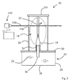
- Figure 1 shows a soot generating device 10 according to the present invention.
- the soot generating device 10 produces a repeatable and constant amount of soot 12 for a given fuel type such that is can be used to calibrate a soot measuring piece of equipment (not shown).
- the soot generating device 10 utilises a stable flame 14 to produce soot 12 and includes a wick 16 which is located relative to a burning zone 18 in which the flame 12 sits during normal use. In ordinary use, the wick is located below the burning zone.
- the burning zone 18 is surrounded by a gas diffusion shield 20 which allows air to pass continuously and evenly into the burning zone 18 for combustion and the production of soot.
- the wick 16 receives fuel 22 from a suitable supply, which in the described embodiment, is provided by a small tank 24 located beneath the burning zone 18 and wick 16 when in normal use.
- the fuel tank 24 includes a vessel having a base 26, on which the soot generating apparatus 10 sits in normal use, side walls 28 and an upper wall 30.
- the wick 16 passes snugly through the upper wall 30 of the tank 24 with one end located within the fuel 22 so as to allow the fuel 22 to drawn up the wick 16 via capillary action for combustion, as is well known in the art.
- a portion of the wick 16 resides above the upper wall 30 of the fuel tank 24 and is surrounded by a shield 32.
- the shield 32 and wick 16 are coterminous such that their respective corresponding ends reside in a common plane at the base of the burning zone 18.
- the shield 32 prevents significant amounts of fuel 22 coming out of the side of the wick 16 thereby resulting in a stable supply to be evaporated from the end face of the wick 16. This aids the creation of a stable flame 14.
- the shield 32 is a hollow cylindrical member having an axis along which the wick 16 lies such that the walls of the shield are substantially equidistantly spaced from the wick 16.
- other configurations of shield may be possible.
- the gas diffusion shield 20 can be any suitable screen or mesh which allows a diffused air flow to enter the burning zone 18 in a uniform and continuous manner to avoid disrupting the stability of the flame 14.
- the diffusion shield 20 is a gauze structure made from a mesh of interwoven wires.
- the gauze is provided in a cylindrical configuration so as to provide a substantially even spacing between it and the flame 14 and soot stream 12.
- the gas diffusion shield 20 is placed approximately equidistantly from the wick 16 on all sides and is axi-symmetrical with respect to the path of the soot stream 12 when in use.
- the gauze is made from wires which have an approximate diameter of 0.3 mm, and which are orthogonally distributed to provide a sheet material having apertures of approximately 1.0 mm. It will be appreciated that a range of wire and aperture dimensions can be considered but it is envisaged that the size of the apertures may range from 0.5 to 2.0 mm, and the wire diameters may range from 0.1 to 0.7 mm.
- the soot 12 is gathered by a collection device 34 which is located above the flame 14 and burning zone 18 in normal use.
- the collection device 34 maybe mounted directly to the gas diffusion shield 20 or may be supported by a frame or other structure which extends up from the tank 24 so as not to disrupt the flow of air entering the burning zone 18. Alternatively, the collection device may be suspended above the gas diffusion shield 20.
- the collection device 34 can be any type of suitable particle filter which collects all of the soot particles before exhausting the remaining hot gas to the environment or some form of scrubber (not shown) if required.
- suitable collection devices 34 are commercially available quartz filters similar to those used in other soot particle measurement instruments. It will be noted that the filter may also collect unburned hydrocarbon and sulphate, but these can be removed after the collection period by heating the filter to >980°C.
- the fuel 22 can be any suitable type, but will preferably be one having a high aromatic content so as to produce a sufficient amount or type of soot 12, or may be specific fuel of interest such as a transport fuel, for example, kerosene.
- the fuel tank 24, wick 16, wick shield 32 and gas diffusion shield 20 can be made from materials known in the art which are suitable for the above described purpose.
- the fuel tank 24 may be plastic or steel
- the wick 16 may be cotton or other cellulose fibre or porous ceramic
- the wick shield 32 may be a heat tolerant rigid material, such as steel.
- the gas diffusion shield 20 may be made from a stainless steel.
- the soot generating device 10 is placed on a flat and level surface on the base 26 of the fuel tank 24. Fuel 22 is loaded into the fuel tank 24 and allowed to rise up the wick 16. Once the wick 16 is primed, the fuel 22 evaporating from the end of the wick 16 can be lit with an appropriate source of ignition. The gas diffusion shield 20 can then be placed over the flame 14 and left until a steady airflow and flame 14 exists. When the flame 14 and soot 12 have steady flows, the collection device 34 can be added and a timer (not shown) started.
- the amount of time which the soot generation is carried out for is dependent on the fuel 22 and the method used to calculate the rate of soot 12 production, but will typically be in excess of 8hrs.
- the soot 12 is collected in a particle filter 34.
- the particle filter 34 is weighed prior to and after the collection of the soot 12 and the difference measurement used to determine the amount collected. This amount can be then be used with the collection time to determine the rate of soot production.
- Other quantities may also be calculated such as the density of the soot stream 12. However, this will require an appreciation of the cross sectional area of the stream of soot 12 which can be obtained as described below.
- Figure 2 shows the soot generating apparatus 10 in use as a calibration standard for a soot measuring device 210.
- the soot measuring device 210 may be any which requires a known quantity of soot production but in the described embodiment is a device which employs a Laser Induced Incandescence, LII, technique.
- LII is well known in the art and involves the use of short laser pulses to rapidly heat the soot particles to induce incandescence which can be detected using appropriately placed detectors, and the results used to calculate the amount of soot concentration in an exhaust gas.
- the cross-sectional area of the soot stream can be determined by translating the beam relative to the soot stream and plotting the LII signal intensity as a function of beam position.
- a horizontal light sheet, perpendicular to soot stream flow direction could be used, and an image of scattered light, or LII, recorded by a camera viewing the light sheet at a small angle to the flow direction. Dimensions of the cross section of the soot stream could be determined from this image when geometric distortions due to the viewing angle are accounted for.
- FIG 2 there is shown a modified soot generating apparatus 10 having similar features as denoted by common reference numerals to those described in relation to Figure 1 .
- the soot collecting device 34 is not required and is replaced by a suitable exhaust system 234.
- the gas diffusion shield 20 includes apertures 236 on either side of the soot stream through which laser beam 238 is fired to provide the LII.
- a detector (not shown) is used to detect the incandescence of the soot particles and determine the soot per volume concentration within the post-flame zone 18 using known techniques. The comparison of the detected amount to the expected amount produced by the soot generating device can then be used to calibrate the soot measuring apparatus 210.
- the detector In most LII systems the detector is placed at right angles to the laser beam direction. However, LII is emitted in all directions and so the detector may be located in other places.
- the gauze will reduce the amount of light collected, but this can be accounted for by calibration with a known intensity light source, for example, a standard blackbody.
- a transparent window could be mounted in the gauze to increase the amount of detected LII, though losses due to reflection at the window surfaces would still have to be accounted for.
- the gas diffusion shield may extend inwards towards the wick shield to allow a flow of air to entrain into the burning zone from beneath the flame.
- the gas diffusion shield may not have evenly distributed apertures but may include one or more holes to allow inspection equipment or sensors or the like to enter the burning zone.
- the gas diffusion shield may not surround the entirety of the burning zone. Portions, for example, the upper portion, may have a solid wall construction, or a reduced flow rate.
- calibrated soot measuring device is an LII device, it is envisaged that other measuring devices may be calibrated using the soot generating device of the invention.
Landscapes
- Chemical & Material Sciences (AREA)
- General Physics & Mathematics (AREA)
- Physics & Mathematics (AREA)
- Health & Medical Sciences (AREA)
- Biochemistry (AREA)
- Analytical Chemistry (AREA)
- Life Sciences & Earth Sciences (AREA)
- General Health & Medical Sciences (AREA)
- Immunology (AREA)
- Pathology (AREA)
- Engineering & Computer Science (AREA)
- Combustion & Propulsion (AREA)
- Nuclear Medicine, Radiotherapy & Molecular Imaging (AREA)
- Investigating Or Analysing Materials By Optical Means (AREA)
Abstract
Description
- This invention relates to a soot generating device which can produce a known amount of soot.
- The examination of pollutants in the exhaust streams of combustion engines is an increasingly important area of interest. One key pollutant is soot created during the combustion cycle. There are numerous techniques for measuring the soot, some of which are laser based like the well known laser induced incandescence, LII. However, the equipment used for LII and similar techniques are difficult to calibrate due to the lack of a reliable calibration standard. This invention seeks to provide an improved calibration standard.
- In a first aspect, the present invention provides a soot generating device suitable for calibration purposes, comprising: a wick located relative to a burning zone; a gas diffusion shield surrounding the burning zone, the gas diffusion shield allowing a continuous stream of air into the combustion zone; a fuel supply for delivering fuel to the wick; and, a collection device for collecting the soot.
- The gas diffusion shield may be a gauze material. The gauze material may include apertures having a maximum diameter of less than 2.0 mm.
- The wick may be surrounded by a shield. The wick and shield may be coterminous relative to a plane define by the terminal end of the shield
- The collection device may be a particle filter.
- The fuel supply may include an aviation, marine, land transport or other prime mover fuel.
- In another aspect, the invention provides a method of calibrating a soot generating device according to the first aspect, comprising: providing the wick with fuel; igniting the fuel so as to provide a flame in the burning zone; burning the fuel for a predetermined time; and, determining a quantity of soot produced for the predetermined time.
- The method may further comprise determining the rate of soot production. The quantity of soot may be determined by weighing the deposited amount.
- The quantity of soot may be collected in a predetermined time which is in excess of 8hrs.
- In a yet further aspect the invention provides a method of calibrating a laser using the soot generating apparatus according to the first aspect, comprising the steps of: generating a known stream of soot with the soot generator; using a sensor of a soot measuring apparatus to be calibrated to sense the soot stream or a portion thereof; comparing the sensed amount of soot with the known amount of soot to provide a measure of calibration.
- The soot measuring apparatus may use a laser induced incandescence technique.
- Embodiments of the invention will now be described with the aid of the following drawings of which:
-
Figure 1 shows a soot generating device according to the present invention. -
Figure 2 shows a soot calibration device according to the present invention. -
Figure 1 shows a soot generatingdevice 10 according to the present invention. The soot generatingdevice 10 produces a repeatable and constant amount ofsoot 12 for a given fuel type such that is can be used to calibrate a soot measuring piece of equipment (not shown). - The
soot generating device 10 utilises astable flame 14 to producesoot 12 and includes awick 16 which is located relative to a burningzone 18 in which theflame 12 sits during normal use. In ordinary use, the wick is located below the burning zone. Theburning zone 18 is surrounded by agas diffusion shield 20 which allows air to pass continuously and evenly into theburning zone 18 for combustion and the production of soot. - The
wick 16 receivesfuel 22 from a suitable supply, which in the described embodiment, is provided by asmall tank 24 located beneath theburning zone 18 andwick 16 when in normal use. Thefuel tank 24 includes a vessel having abase 26, on which thesoot generating apparatus 10 sits in normal use,side walls 28 and anupper wall 30. Thewick 16 passes snugly through theupper wall 30 of thetank 24 with one end located within thefuel 22 so as to allow thefuel 22 to drawn up thewick 16 via capillary action for combustion, as is well known in the art. - A portion of the
wick 16 resides above theupper wall 30 of thefuel tank 24 and is surrounded by ashield 32. Theshield 32 andwick 16 are coterminous such that their respective corresponding ends reside in a common plane at the base of theburning zone 18. Theshield 32 prevents significant amounts offuel 22 coming out of the side of thewick 16 thereby resulting in a stable supply to be evaporated from the end face of thewick 16. This aids the creation of astable flame 14. In the present embodiment, theshield 32 is a hollow cylindrical member having an axis along which thewick 16 lies such that the walls of the shield are substantially equidistantly spaced from thewick 16. However, it will be appreciated that other configurations of shield may be possible. - The
gas diffusion shield 20 can be any suitable screen or mesh which allows a diffused air flow to enter theburning zone 18 in a uniform and continuous manner to avoid disrupting the stability of theflame 14. - In the present embodiment, the
diffusion shield 20 is a gauze structure made from a mesh of interwoven wires. The gauze is provided in a cylindrical configuration so as to provide a substantially even spacing between it and theflame 14 andsoot stream 12. Thus, thegas diffusion shield 20 is placed approximately equidistantly from thewick 16 on all sides and is axi-symmetrical with respect to the path of thesoot stream 12 when in use. In the present embodiment, the gauze is made from wires which have an approximate diameter of 0.3 mm, and which are orthogonally distributed to provide a sheet material having apertures of approximately 1.0 mm. It will be appreciated that a range of wire and aperture dimensions can be considered but it is envisaged that the size of the apertures may range from 0.5 to 2.0 mm, and the wire diameters may range from 0.1 to 0.7 mm. - The
soot 12 is gathered by acollection device 34 which is located above theflame 14 and burningzone 18 in normal use. Thecollection device 34 maybe mounted directly to thegas diffusion shield 20 or may be supported by a frame or other structure which extends up from thetank 24 so as not to disrupt the flow of air entering theburning zone 18. Alternatively, the collection device may be suspended above thegas diffusion shield 20. - The
collection device 34 can be any type of suitable particle filter which collects all of the soot particles before exhausting the remaining hot gas to the environment or some form of scrubber (not shown) if required. Examples ofsuitable collection devices 34 are commercially available quartz filters similar to those used in other soot particle measurement instruments. It will be noted that the filter may also collect unburned hydrocarbon and sulphate, but these can be removed after the collection period by heating the filter to >980°C. - The
fuel 22 can be any suitable type, but will preferably be one having a high aromatic content so as to produce a sufficient amount or type ofsoot 12, or may be specific fuel of interest such as a transport fuel, for example, kerosene. - The
fuel tank 24,wick 16,wick shield 32 andgas diffusion shield 20 can be made from materials known in the art which are suitable for the above described purpose. For example, thefuel tank 24 may be plastic or steel, thewick 16 may be cotton or other cellulose fibre or porous ceramic and thewick shield 32 may be a heat tolerant rigid material, such as steel. Thegas diffusion shield 20 may be made from a stainless steel. - In use, the
soot generating device 10 is placed on a flat and level surface on thebase 26 of thefuel tank 24.Fuel 22 is loaded into thefuel tank 24 and allowed to rise up thewick 16. Once thewick 16 is primed, thefuel 22 evaporating from the end of thewick 16 can be lit with an appropriate source of ignition. Thegas diffusion shield 20 can then be placed over theflame 14 and left until a steady airflow andflame 14 exists. When theflame 14 andsoot 12 have steady flows, thecollection device 34 can be added and a timer (not shown) started. - The amount of time which the soot generation is carried out for is dependent on the
fuel 22 and the method used to calculate the rate ofsoot 12 production, but will typically be in excess of 8hrs. In one embodiment, thesoot 12 is collected in aparticle filter 34. Theparticle filter 34 is weighed prior to and after the collection of thesoot 12 and the difference measurement used to determine the amount collected. This amount can be then be used with the collection time to determine the rate of soot production. Other quantities may also be calculated such as the density of thesoot stream 12. However, this will require an appreciation of the cross sectional area of the stream ofsoot 12 which can be obtained as described below. -
Figure 2 shows thesoot generating apparatus 10 in use as a calibration standard for asoot measuring device 210. Thesoot measuring device 210 may be any which requires a known quantity of soot production but in the described embodiment is a device which employs a Laser Induced Incandescence, LII, technique. LII is well known in the art and involves the use of short laser pulses to rapidly heat the soot particles to induce incandescence which can be detected using appropriately placed detectors, and the results used to calculate the amount of soot concentration in an exhaust gas. - If a laser beam or laser light sheet much smaller than the soot stream is used in LII, the cross-sectional area of the soot stream can be determined by translating the beam relative to the soot stream and plotting the LII signal intensity as a function of beam position. Alternatively, a horizontal light sheet, perpendicular to soot stream flow direction, could be used, and an image of scattered light, or LII, recorded by a camera viewing the light sheet at a small angle to the flow direction. Dimensions of the cross section of the soot stream could be determined from this image when geometric distortions due to the viewing angle are accounted for.
- In
Figure 2 , there is shown a modifiedsoot generating apparatus 10 having similar features as denoted by common reference numerals to those described in relation toFigure 1 . However, in the embodiment ofFigure 2 , thesoot collecting device 34 is not required and is replaced by asuitable exhaust system 234. Also, thegas diffusion shield 20 includesapertures 236 on either side of the soot stream through whichlaser beam 238 is fired to provide the LII. - A detector (not shown) is used to detect the incandescence of the soot particles and determine the soot per volume concentration within the
post-flame zone 18 using known techniques. The comparison of the detected amount to the expected amount produced by the soot generating device can then be used to calibrate thesoot measuring apparatus 210. - In most LII systems the detector is placed at right angles to the laser beam direction. However, LII is emitted in all directions and so the detector may be located in other places. The gauze will reduce the amount of light collected, but this can be accounted for by calibration with a known intensity light source, for example, a standard blackbody. Alternatively, a transparent window could be mounted in the gauze to increase the amount of detected LII, though losses due to reflection at the window surfaces would still have to be accounted for.
- It will be appreciated that other modifications may be included within the scope of the claimed invention. For example, the gas diffusion shield may extend inwards towards the wick shield to allow a flow of air to entrain into the burning zone from beneath the flame. Also, the gas diffusion shield may not have evenly distributed apertures but may include one or more holes to allow inspection equipment or sensors or the like to enter the burning zone. Further, the gas diffusion shield may not surround the entirety of the burning zone. Portions, for example, the upper portion, may have a solid wall construction, or a reduced flow rate.
- Although the description of the calibrated soot measuring device is an LII device, it is envisaged that other measuring devices may be calibrated using the soot generating device of the invention.
Claims (13)
- A soot generating device (10) suitable for calibration purposes, comprising:a wick (16) located relative to a burning zone (18);a gas diffusion shield (20) surrounding the burning zone, the gas diffusion shield allowing a continuous stream of air into the combustion zone;,a fuel supply (22) for delivering fuel to the wick; and,a collection device (34) for collecting the soot.
- A device as claimed in claim 1, wherein the gas diffusion shield is a gauze material.
- A device as claimed in claim 2, wherein the gauze material includes apertures having a maximum diameter of less than 2.0 mm.
- A device as claimed in any preceding claim wherein the wick is surrounded by a shield (32).
- A device as claimed in claim 4, wherein the wick and shield are coterminous relative to a plane defined by the terminal end of the shield
- A device as claimed in any preceding claim 5, wherein the collection device is a particle filter.
- A device as claimed in any preceding claim wherein the fuel supply includes an aviation, marine, land transport or other prime mover fuel.
- A method of calibrating a soot generating device according to claims 1 to 7, comprising:providing the wick with fuel;igniting the fuel so as to provide a flame in the burning zone;burning the fuel for a predetermined time; and,determining a quantity of soot produced for the predetermined time.
- A method as claimed in claim 8, further comprising determining the rate of soot production.
- A method as claimed in claim 9, wherein the quantity of soot is determined by weighing the deposited amount.
- A method as claimed in any of claims 8 to 10, wherein the quantity of soot is collected in a predetermined time which is in excess of 8hrs.
- A method of calibrating a laser (238) using the soot generating apparatus of any of claims 1 to 7, comprising the steps of:generating a known stream of soot (12) with the soot generating apparatus (10);using a sensor of a soot measuring apparatus to be calibrated to sense the soot stream or a portion thereof;comparing the sensed amount of soot with the known amount of soot to provide a measure of calibration.
- A method as claimed in claim 12, wherein the soot measuring apparatus uses a laser induced incandescence technique.
Applications Claiming Priority (1)
| Application Number | Priority Date | Filing Date | Title |
|---|---|---|---|
| GBGB1316637.6A GB201316637D0 (en) | 2013-09-19 | 2013-09-19 | A soot generating device |
Publications (1)
| Publication Number | Publication Date |
|---|---|
| EP2851673A1 true EP2851673A1 (en) | 2015-03-25 |
Family
ID=49553078
Family Applications (1)
| Application Number | Title | Priority Date | Filing Date |
|---|---|---|---|
| EP14182391.4A Withdrawn EP2851673A1 (en) | 2013-09-19 | 2014-08-27 | A soot generating device |
Country Status (3)
| Country | Link |
|---|---|
| US (1) | US9645049B2 (en) |
| EP (1) | EP2851673A1 (en) |
| GB (1) | GB201316637D0 (en) |
Cited By (2)
| Publication number | Priority date | Publication date | Assignee | Title |
|---|---|---|---|---|
| CN106290155A (en) * | 2016-08-02 | 2017-01-04 | 钢研纳克检测技术有限公司 | One is applied to ICP spectrogrph light source shield structure |
| CN113447403A (en) * | 2021-06-11 | 2021-09-28 | 南京航空航天大学 | Heating device for measuring spectral emissivity of high-temperature particle curtain |
Families Citing this family (2)
| Publication number | Priority date | Publication date | Assignee | Title |
|---|---|---|---|---|
| DE102015011853A1 (en) * | 2015-09-10 | 2017-03-16 | Man Truck & Bus Ag | Aerosol generator, in particular soot generator |
| CN114636784B (en) * | 2022-03-09 | 2023-09-01 | 安徽工程大学 | Method and equipment for testing and evaluating combustion performance of down feather |
Citations (1)
| Publication number | Priority date | Publication date | Assignee | Title |
|---|---|---|---|---|
| GB2087541A (en) * | 1980-11-14 | 1982-05-26 | Chang Chieh | A kerosene stove device |
Family Cites Families (12)
| Publication number | Priority date | Publication date | Assignee | Title |
|---|---|---|---|---|
| GB208754A (en) | 1922-09-01 | 1924-01-01 | Sunbeam Motor Car Co Ltd | Improvements in friction transmission clutches |
| JPS57134604A (en) | 1981-02-10 | 1982-08-19 | Matsushita Electric Ind Co Ltd | Petroleum combustion unit |
| FI70467C (en) * | 1984-05-22 | 1986-09-19 | Juhava Oy | LAMPA |
| US5051090A (en) * | 1990-04-09 | 1991-09-24 | Nippon Steel Corporation | Method and apparatus for burning liquid fuel |
| US5206176A (en) * | 1990-10-02 | 1993-04-27 | Massachusetts Institute Of Technology | Detection and control of aromatic compounds in combustion effluent |
| ATE249008T1 (en) | 1999-05-26 | 2003-09-15 | Lianpeng Jing | BURNER FOR PRODUCING SOOT |
| US7167240B2 (en) * | 2002-07-19 | 2007-01-23 | Columbian Chemicals Company | Carbon black sampling for particle surface area measurement using laser-induced incandescence and reactor process control based thereon |
| DE10243307B4 (en) * | 2002-09-13 | 2006-06-08 | Deutsches Zentrum für Luft- und Raumfahrt e.V. | Apparatus and method for the controlled production of nano soot particles |
| US7303598B1 (en) * | 2003-03-05 | 2007-12-04 | Altex Technologies | Liquid fuel preprocessor |
| EP1616914A1 (en) | 2004-07-12 | 2006-01-18 | Matter Engineering AG | Apparatus for Producing Carbon Black |
| EP1842880B1 (en) | 2006-04-06 | 2017-03-08 | Testo AG | Soot generator |
| TW201510442A (en) * | 2013-09-05 | 2015-03-16 | Pro Iroda Ind Inc | Wick of flaming device |
-
2013
- 2013-09-19 GB GBGB1316637.6A patent/GB201316637D0/en not_active Ceased
-
2014
- 2014-08-27 US US14/470,254 patent/US9645049B2/en not_active Expired - Fee Related
- 2014-08-27 EP EP14182391.4A patent/EP2851673A1/en not_active Withdrawn
Patent Citations (1)
| Publication number | Priority date | Publication date | Assignee | Title |
|---|---|---|---|---|
| GB2087541A (en) * | 1980-11-14 | 1982-05-26 | Chang Chieh | A kerosene stove device |
Non-Patent Citations (4)
| Title |
|---|
| BRENDYN G SARNACKI ET AL: "Uncertainties of Soot Measurement in Counterflow Flames using Laser Induced Incandescence: Soot Volume Fraction, Particle Size, and Number Density", 8TH US NATIONAL COMBUSTION MEETING 2013 VOLUME 2, 20 May 2013 (2013-05-20), pages 979 - 983, XP055562426, Retrieved from the Internet <URL:https://sutherland.che.utah.edu/USCI2013/PAPERS/1F01-070DI-0029.pdf> [retrieved on 20190227] * |
| DR. SHAHRIAR KHAN: "Fossil Fuel and the Environment", 14 March 2012, INTECH, ISBN: 978-953-51-0277-9, article KAZUHIRO HAYASHIDA, KATSUHIKO HAJI: "Effects of Fuel Properties on Diffusion Combustion and Deposit Accumulation,", pages: 1 - 16, XP002734621 * |
| SMEDLEY JOANNE M., WILLIAMS A.: "Soot deposition from ethylene/air flames and the role of aromatic intermediates", ACS FUELS:SYMPOSIUM ON COMBUSTION CHEMISTRY:LARGE AROMATICS, FULLERENES AND SOOT, vol. 36, no. 4, 1 August 1991 (1991-08-01), pages 1501 - 1508, XP002734620 * |
| SNELLING D R ET AL: "TWO-DIMENSIONAL IMAGING OF SOOT VOLUME FRACTION IN LAMINAR DIFFUSION FLAMES", APPLIED OPTICS, OPTICAL SOCIETY OF AMERICA, WASHINGTON, DC; US, vol. 38, no. 12, 20 April 1999 (1999-04-20), pages 2478 - 2485, XP000828564, ISSN: 0003-6935, DOI: 10.1364/AO.38.002478 * |
Cited By (3)
| Publication number | Priority date | Publication date | Assignee | Title |
|---|---|---|---|---|
| CN106290155A (en) * | 2016-08-02 | 2017-01-04 | 钢研纳克检测技术有限公司 | One is applied to ICP spectrogrph light source shield structure |
| CN113447403A (en) * | 2021-06-11 | 2021-09-28 | 南京航空航天大学 | Heating device for measuring spectral emissivity of high-temperature particle curtain |
| CN113447403B (en) * | 2021-06-11 | 2022-05-03 | 南京航空航天大学 | Heating device for measuring spectral emissivity of high-temperature particle curtain |
Also Published As
| Publication number | Publication date |
|---|---|
| US9645049B2 (en) | 2017-05-09 |
| US20150076331A1 (en) | 2015-03-19 |
| GB201316637D0 (en) | 2013-11-06 |
Similar Documents
| Publication | Publication Date | Title |
|---|---|---|
| US9645049B2 (en) | Soot generating device | |
| US10788474B2 (en) | Online monitor for trace sodium in high-purity water, and online monitoring method and device thereof | |
| Moallemi et al. | Characterization of black carbon particles generated by a propane-fueled miniature inverted soot generator | |
| CN205941424U (en) | Heat of combustion rate of release test system under low pressure environment | |
| TW201506375A (en) | Particle detection system and related methods | |
| JPH1082701A (en) | Temperature measuring device | |
| Dierks et al. | Quantification of methane gas leakages using remote sensing and sensor data fusion | |
| CN105588792A (en) | Two-dimensional smoke concentration field measuring device based on sheet light source | |
| CN102608010B (en) | Particulate matter (PM) detecting method and equipment | |
| CN106769721A (en) | A kind of particulate pollutant concentration light scattering measurement device and measuring method | |
| US20130195245A1 (en) | Method for characterizing flame and spray structures in windowless chambers | |
| Hagen et al. | Hydration properties of combustion aerosols | |
| JPS6036825A (en) | Control method for combustion flame and device thereof | |
| KR20190020403A (en) | Cameras with fine dust detection | |
| Lee et al. | Quantitative measurements of soot particles in a laminar diffusion flame using a LII/LIS technique | |
| CN204439539U (en) | A kind of optical system of flue gas monitoring instrument and pick-up unit | |
| AU2015281304B2 (en) | Device and method for calibrating a scattered light meter | |
| Chung et al. | In situ light scattering measurements of mainstream and sidestream cigarette smoke | |
| CN205449753U (en) | Two dimension smog concentration field measuring device based on sheet laser | |
| CN102095773A (en) | Smoke oxygen content measurement method and system | |
| Tsantaridis | Smoke, gas and heat release data for building products in the cone calorimeter | |
| CN102095774B (en) | Smoke dry oxygen content measurement method and system | |
| CN107505292B (en) | Device and method for measuring infrared transmittance of infrared interference smoke screen in vacuum | |
| Johnson et al. | Development of techniques to characterize particulates emitted from gas turbine exhausts | |
| RU77441U1 (en) | DEVICE FOR MEASURING THE CONDENSED PHASE CONTENT IN A GENERATOR GAS OF A LIQUID ROCKET ENGINE |
Legal Events
| Date | Code | Title | Description |
|---|---|---|---|
| PUAI | Public reference made under article 153(3) epc to a published international application that has entered the european phase |
Free format text: ORIGINAL CODE: 0009012 |
|
| 17P | Request for examination filed |
Effective date: 20140827 |
|
| AK | Designated contracting states |
Kind code of ref document: A1 Designated state(s): AL AT BE BG CH CY CZ DE DK EE ES FI FR GB GR HR HU IE IS IT LI LT LU LV MC MK MT NL NO PL PT RO RS SE SI SK SM TR |
|
| AX | Request for extension of the european patent |
Extension state: BA ME |
|
| RAP1 | Party data changed (applicant data changed or rights of an application transferred) |
Owner name: ROLLS-ROYCE PLC |
|
| R17P | Request for examination filed (corrected) |
Effective date: 20150922 |
|
| RBV | Designated contracting states (corrected) |
Designated state(s): AL AT BE BG CH CY CZ DE DK EE ES FI FR GB GR HR HU IE IS IT LI LT LU LV MC MK MT NL NO PL PT RO RS SE SI SK SM TR |
|
| STAA | Information on the status of an ep patent application or granted ep patent |
Free format text: STATUS: EXAMINATION IS IN PROGRESS |
|
| 17Q | First examination report despatched |
Effective date: 20190307 |
|
| STAA | Information on the status of an ep patent application or granted ep patent |
Free format text: STATUS: THE APPLICATION HAS BEEN WITHDRAWN |
|
| 18W | Application withdrawn |
Effective date: 20190702 |