EP2851613B1 - Tuned composite optical arrangement for LED array - Google Patents
Tuned composite optical arrangement for LED array Download PDFInfo
- Publication number
- EP2851613B1 EP2851613B1 EP14185145.1A EP14185145A EP2851613B1 EP 2851613 B1 EP2851613 B1 EP 2851613B1 EP 14185145 A EP14185145 A EP 14185145A EP 2851613 B1 EP2851613 B1 EP 2851613B1
- Authority
- EP
- European Patent Office
- Prior art keywords
- led
- light
- linear
- reflecting surfaces
- reflecting
- Prior art date
- Legal status (The legal status is an assumption and is not a legal conclusion. Google has not performed a legal analysis and makes no representation as to the accuracy of the status listed.)
- Not-in-force
Links
- 230000003287 optical effect Effects 0.000 title claims description 88
- 239000002131 composite material Substances 0.000 title 1
- 230000000712 assembly Effects 0.000 description 3
- 238000000429 assembly Methods 0.000 description 3
- 238000005286 illumination Methods 0.000 description 3
- 230000005855 radiation Effects 0.000 description 3
- 230000011664 signaling Effects 0.000 description 3
- 238000003491 array Methods 0.000 description 2
- 230000006978 adaptation Effects 0.000 description 1
- 230000000295 complement effect Effects 0.000 description 1
- 238000001816 cooling Methods 0.000 description 1
- 238000010586 diagram Methods 0.000 description 1
- 238000005516 engineering process Methods 0.000 description 1
- 230000007613 environmental effect Effects 0.000 description 1
- 230000014759 maintenance of location Effects 0.000 description 1
- 239000000463 material Substances 0.000 description 1
- 238000012986 modification Methods 0.000 description 1
- 230000004048 modification Effects 0.000 description 1
- 230000000717 retained effect Effects 0.000 description 1
- 239000007787 solid Substances 0.000 description 1
Images




Classifications
-
- F—MECHANICAL ENGINEERING; LIGHTING; HEATING; WEAPONS; BLASTING
- F21—LIGHTING
- F21V—FUNCTIONAL FEATURES OR DETAILS OF LIGHTING DEVICES OR SYSTEMS THEREOF; STRUCTURAL COMBINATIONS OF LIGHTING DEVICES WITH OTHER ARTICLES, NOT OTHERWISE PROVIDED FOR
- F21V7/00—Reflectors for light sources
- F21V7/04—Optical design
- F21V7/06—Optical design with parabolic curvature
-
- F—MECHANICAL ENGINEERING; LIGHTING; HEATING; WEAPONS; BLASTING
- F21—LIGHTING
- F21V—FUNCTIONAL FEATURES OR DETAILS OF LIGHTING DEVICES OR SYSTEMS THEREOF; STRUCTURAL COMBINATIONS OF LIGHTING DEVICES WITH OTHER ARTICLES, NOT OTHERWISE PROVIDED FOR
- F21V13/00—Producing particular characteristics or distribution of the light emitted by means of a combination of elements specified in two or more of main groups F21V1/00 - F21V11/00
- F21V13/02—Combinations of only two kinds of elements
- F21V13/04—Combinations of only two kinds of elements the elements being reflectors and refractors
-
- F—MECHANICAL ENGINEERING; LIGHTING; HEATING; WEAPONS; BLASTING
- F21—LIGHTING
- F21V—FUNCTIONAL FEATURES OR DETAILS OF LIGHTING DEVICES OR SYSTEMS THEREOF; STRUCTURAL COMBINATIONS OF LIGHTING DEVICES WITH OTHER ARTICLES, NOT OTHERWISE PROVIDED FOR
- F21V5/00—Refractors for light sources
- F21V5/04—Refractors for light sources of lens shape
-
- F—MECHANICAL ENGINEERING; LIGHTING; HEATING; WEAPONS; BLASTING
- F21—LIGHTING
- F21V—FUNCTIONAL FEATURES OR DETAILS OF LIGHTING DEVICES OR SYSTEMS THEREOF; STRUCTURAL COMBINATIONS OF LIGHTING DEVICES WITH OTHER ARTICLES, NOT OTHERWISE PROVIDED FOR
- F21V7/00—Reflectors for light sources
- F21V7/005—Reflectors for light sources with an elongated shape to cooperate with linear light sources
-
- F—MECHANICAL ENGINEERING; LIGHTING; HEATING; WEAPONS; BLASTING
- F21—LIGHTING
- F21V—FUNCTIONAL FEATURES OR DETAILS OF LIGHTING DEVICES OR SYSTEMS THEREOF; STRUCTURAL COMBINATIONS OF LIGHTING DEVICES WITH OTHER ARTICLES, NOT OTHERWISE PROVIDED FOR
- F21V7/00—Reflectors for light sources
- F21V7/04—Optical design
- F21V7/09—Optical design with a combination of different curvatures
-
- F—MECHANICAL ENGINEERING; LIGHTING; HEATING; WEAPONS; BLASTING
- F21—LIGHTING
- F21Y—INDEXING SCHEME ASSOCIATED WITH SUBCLASSES F21K, F21L, F21S and F21V, RELATING TO THE FORM OR THE KIND OF THE LIGHT SOURCES OR OF THE COLOUR OF THE LIGHT EMITTED
- F21Y2103/00—Elongate light sources, e.g. fluorescent tubes
- F21Y2103/10—Elongate light sources, e.g. fluorescent tubes comprising a linear array of point-like light-generating elements
-
- F—MECHANICAL ENGINEERING; LIGHTING; HEATING; WEAPONS; BLASTING
- F21—LIGHTING
- F21Y—INDEXING SCHEME ASSOCIATED WITH SUBCLASSES F21K, F21L, F21S and F21V, RELATING TO THE FORM OR THE KIND OF THE LIGHT SOURCES OR OF THE COLOUR OF THE LIGHT EMITTED
- F21Y2115/00—Light-generating elements of semiconductor light sources
- F21Y2115/10—Light-emitting diodes [LED]
Definitions
- the present disclosure relates generally to warning light devices, and more particularly to optical configurations for producing integrated directional light from a LED light sources.
- LED's have characteristic spatial radiation patterns with respect to an optical axis which passes through the light emitting die.
- a common characteristic of LED radiation patterns is that light is emitted in a pattern surrounding the optical axis from one side of an imaginary plane containing the light emitting die, the optical axis being oriented perpendicular to this plane and emanating from a center of the die.
- the light generated by an LED is radiated within a hemisphere centered on the optical axis, with a majority of the light emitted at angles close to the optical axis of the LED.
- LED's can be described as "directional" light sources, since all of the light they generate is emitted from one side of the device, with the other side dedicated to a support that provides electrical power to the LED and conducts heat away from the die.
- Subject of the invention is an LED optical assembly comprising a plurality of light emitting diodes and a pair of longitudinal reflecting surfaces.
- the plurality of light emitting diodes (LEDs) each have an optical axis and a light emission pattern surrounding said optical axis.
- the plurality of LEDs are arranged in a linear array on a substantially planar support and provided with connections to electrical power.
- the linear array has a length and the optical axes of said plurality of LEDs are included in a first plane perpendicular to said planar support.
- the pair of longitudinal reflecting surfaces are separated by said first plane and extend along opposite sides of said linear array.
- the longitudinal reflecting surfaces define a trough having a generally parabolic sectional configuration and a linear focal axis passing through the light emitting dies of said LEDs.
- the through includes surfaces of rotation extending from a bottom edge to a top edge of each said reflecting surface and are defined by a curve rotated about the optical axis of each said LED.
- the trough includes linear reflecting portions defined by a curve projected along the linear focal axis. The linear reflecting portions are alternating with said surfaces of rotation. Light emitted from said at least one LED and incident upon said surfaces of rotation is redirected into trajectories parallel with the optical axis of said at least one LED. Light incident upon said linear reflecting portions is redirected into trajectories at an angle of less than 20° divergence from said first plane.
- the present disclosure includes an optical assembly configured to produce an integrated light emission pattern relative to a first plane with limited spread in imaginary planes perpendicular to the first plane.
- light emitted from an LED can be described as "narrow angle” light emitted at an angle of less than about 45° from the optical axis and "wide angle” light emitted at an angle of more than about 45° from the optical axis O A as shown in Figure 6 .
- the initial trajectory of wide angle and narrow angle light may necessitate manipulation by different portions of a reflector and/or optical element to provide the desired illumination pattern.
- a plurality of LEDs may be arranged on a support in a linear array, with the optical axes of the LEDs included in a first imaginary plane perpendicular to the support.
- An imaginary linear focal axis extends through the dies of the plurality of LEDs.
- Reflecting surfaces may extend along either side of the array, forming a concave reflective trough.
- the reflective trough may be generally defined by a parabolic curve having a focus coincident with the linear focal axis and projected along said axis to form a linear parabolic structure on which reflecting surfaces can be arranged.
- An elongated lens may be positioned above the LEDs and longitudinally bisected by the first imaginary plane.
- the elongated lens and trough are configured so that light may not be emitted from the optical assembly without passing through the elongated lens or being redirected by the trough reflector.
- the elongated lens can be configured to redirect light emitted from the array of LEDs (and not incident upon the reflecting trough) from its emitted trajectory into imaginary planes parallel with the first plane.
- the reflective trough is preferably configured to redirect wide angle light (light not passing through the elongated lens) from a range of emitted trajectories into a range of reflected trajectories closer to the first plane.
- the redirection performed by the elongated lens may be described as "partially collimated” or “collimated with respect to the first plane.”
- Such partially collimated light retains the component of its emitted trajectory within the imaginary planes into which it is redirected, whereas fully collimated light is parallel with a line such as the optical axis of an LED.
- Medial reflecting surfaces may also be positioned between adjacent pairs of LEDs, to redirect a portion of the wide angle light from each LED into imaginary planes perpendicular to the first imaginary plane containing the optical axes of the LEDs. This subset of wide angle light from each LED is partially collimated with respect to an imaginary plane perpendicular to the first plane and including the optical axis of the respective LED. Light reflected from the medial reflecting surfaces retains the component of its emitted trajectory within the imaginary planes into which it is redirected, however this light must be further redirected by the elongated lens or trough reflector before being emitted from the optical assembly. Thus, the subset of wide angle light incident upon the medial reflectors may be fully collimated with respect to the respective LED optical axis before exiting the optical assembly, depending upon the specific configuration of the elongated lens and trough reflector.
- the shape of the medial reflecting surfaces is dictated by their function, e.g., redirecting this subset of wide angle light into trajectories having a smaller angular component with respect to imaginary planes perpendicular to both the first plane (containing the optical axes of the LEDs) and a second plane containing the light emitting dies of the LEDs. These planes may intersect at the linear focal axis of the assembly.
- the die of each LED typically includes a base that supports the light emitting die above a plane defined by a PC board upon which the LEDs are mounted.
- the imaginary second plane discussed in this application includes the LED dies and an imaginary linear focal axis passing through the LED dies.
- the medial reflecting surfaces may take many forms, but preferably comprise a convex surface when viewed looking toward the LED support (PC board).
- a preferred surface configuration for the medial reflecting surface partially collimates the subset of wide angle light incident upon the medial reflecting surfaces into imaginary planes substantially perpendicular to both the first plane containing the LED optical axes and the second plane passing through the LED dies.
- the medial reflecting surfaces may be defined by a segment of a parabola having a focus centered on the light emitting die of a respective LED. This parabolic segment is then rotated about the imaginary linear focal axis of the array to form a three dimensional surface.
- the medial reflecting surfaces on either side of a respective LED may be mirror images of each other and adjacent medial reflecting surfaces may meet at a semicircular peak.
- Other surface configurations approximating the intended function of the disclosed medial reflecting surfaces will occur to those skilled in the art.
- a semi-conical surface is an example of such an alternative configuration.
- the subset of wide angle light redirected by the medial reflecting surfaces would continue on its emitted trajectory and be lost (absorbed or scattered) within the assembly or be partially collimated by the trough reflector and elongated lens (into imaginary planes parallel with the first plane containing the LED optical axes).
- the retained component of the emitted trajectory of this subset of wide angle light (within the imaginary planes) means it cannot contribute to a majority of desirable light emission patterns and is effectively wasted.
- the reflecting trough of the disclosed embodiment may be constructed from a plurality of reflecting surfaces, some of which are surfaces of rotation centered on the optical axis of an LED and others are linear surfaces defined by a curve projected along the length of the trough. Each surface is selected to re-direct light incident upon it into a range of trajectories that will contribute to a desired light emission pattern. The size and/or shape of each of the several reflecting surfaces may be adjusted to provide a desired light emission pattern.
- reflecting surfaces may be formed as an internal reflecting surface or as polished or metalized external surfaces. Both types of surfaces are intended to be encompassed in the appended claims.
- LED optical assemblies will now be described with reference to the figures, in which common reference numerals are used to designate similar components.
- Figures 1, 2, 4, 5,and 7-11 illustrate a first optical assembly according to aspects of the disclosure.
- Figures 3 and 6 are used to illustrate exemplary LED light emitters in functional conjunction with portions of an optical assembly.
- Figures 12-16 are diagrams used to illustrate a preferred geometry of the optical assembly according to aspects of the present disclosure.
- the disclosed LED optical assemblies are suitable for use in emergency vehicle warning lights, but the disclosed optical assemblies may be appropriate for use in other warning and signaling apparatus as well as general illumination applications.
- the disclosed optical assembly 10 includes a trough reflector 12 and a longitudinal lens 14. As shown in Figures 1 , 4 , 5 , 7 and 9 , the lens 14 extends the length of the trough reflector 12. Projections 16 at either end of the lens 14 fit into cradle openings 18 at either end of the reflector 12. As best seen in Figures 4, 5, and 7-9 , the reflector 12 and lens 14 are configured to snap together, with the projections 16 of the longitudinal lens 14 received in the cradle openings 18. With reference to Figure 8 , each cradle opening 18 is partially bounded by a pair of shoulders 15 and a retention tab 17.
- the projections 16 at the ends of the lens 14 have a configuration complementary to the shoulders 15 and tab 17.
- the projection 16 at one end of the lens 14 is inserted into a cradle opening 18 and advanced through the opening against the resilient movement of the tab 17.
- the lens 14 is pushed into the reflector trough until the projection 16 bears on the tab 17 at the opposite end, which flexes to permit the lens projections 16 to be seated in their respective cradle openings 18 and held in place by the tabs 17.
- the disclosed lens 14 also includes a fastener receptacle 20, which also functions as a standoff to maintain the central portion of the length of the longitudinal lens 14 in position above the array of LEDs 22. Securing the lens 14 at both ends and in the middle helps prevent the lens from bowing away from the intended straight position under the influence of changing environmental conditions (temperature).
- a fastener (not shown) extends through a heat sink and a PC board (not shown) to pull the reflector 12 and lens 14 into an installed position and maintain an efficient thermal contact between the PC board and the heat sink.
- the lens 14 includes a convex light input surface 24 facing the LEDs and a convex light emission surface 26 facing away from the LEDs 22.
- the convex curves defining the light input surface 24 and light emission surface 26 are projected along the length of the lens 14, resulting in a substantially constant sectional configuration.
- the geometry of the lens 14 is illustrated in Figure 12 , which is a sectional view of the lens 14 in operational position relative to an LED light source 22.
- the lens 14 is configured to have a linear focus coincident with a linear focal axis A L passing through the dies of the plurality of LEDs 22 as shown in Figure 2 .
- Input surface 24 is defined by an aspheric curve calculated according to Fermat's Principal, using the distance from the LED 22 and the refractive index of the lens material.
- the light emitting surface 26 is calculated to result in light from the LED 22 passing through the lens 14 being collimated into rays parallel with the optical axis of the LED 22.
- the resulting light emitting surface 26 is defined by an elliptical curve as shown in Figure 12 .
- the upper and lower margins of the lens 14 are angled to permit light to pass above and below the lens 14 to be handled by the reflecting surfaces of the trough reflector 12. If the light from an LED is incident upon the light input surface 24, then it will be "partially collimated" into planes parallel with the optical axis A O and first plane P 1 , but will retain the angular component of its emission within those planes. The divergent portions of this light will enhance light emission to either side of the center of the optical arrangement parallel with plane P 1 .
- Other lens configurations will occur to those skilled in the art which will accomplish the function of partially collimating light from the LEDs and are compatible with the present disclosure.
- the reflector 12 in the disclosed embodiments includes parallel, mirror image reflecting surfaces extending along each side of the array of LEDs 22.
- the function of the reflector is to redirect light originating from the LEDs 22 into a range of angles having trajectories close to planes parallel with plane P 1 which includes the optical axes O A of the LEDs 22.
- the trough reflector 12 is generally defined by a parabola 28 having a focus at the die of the LED 22.
- the shape of the reflector 12 is modified by superimposing surfaces defined by other curves onto the parabola 28 as will be discussed below.
- the disclosed trough reflector includes at least four distinct reflecting surfaces, each handling different portions of the light from the LEDs 22 and producing a portion of the resulting light emission pattern.
- Medial reflecting surfaces 30 are positioned to either side of each LED 22 and centered on the linear focal axis A L . These surfaces are defined by portions of parabola 28 rotated about the linear focal axis A L . The resulting surfaces of rotation redirect wide angle light from the LEDs 22 into planes such as P 3 perpendicular to both the first plane P 1 (containing the optical axes A O of the LEDs 22) and the second plane P 2 (containing the light emitting dies of the LEDs 22).
- Other non-parabolic surfaces, such as conical surfaces may be used for the medial reflecting surfaces 30 as will occur to those skilled in the art.
- the trough reflector 12 has two mirror image parallel reflecting surfaces. Each of these surfaces includes three distinct reflecting portions.
- Rotated portions 32 extend from the bottom to the top of the trough in a direction parallel with plane P 3 as shown in Figure 2 . Rotated portions 32 are arranged in pairs on opposite sides of each LED 22. Each rotated portion 32 is defined by a segment of parabola 28 rotated about the optical axis A O of the LED 22 between the pair of rotated portions 32. Thus, each rotated portion 32 is a surface of rotation defined by a segment of a rotated parabola. Other curves rotated about the optical axis A O of the LED 22 may be compatible with the disclosed optical arrangement.
- This rotated surface configuration is designed to fully collimate divergent light incident upon it into a beam parallel with the optical axis A O of the respective LED 22. This light reinforces the on axis peak light output of the optical assembly 10.
- the width W of the parabolic portions 32 coincides with the distance D between the medial reflecting surfaces 30.
- Parabolic portions 32 separate concave linear reflecting surface portions 34, 36 and 38, which extend up the trough reflector 12 from bottom to top.
- Each of the linear reflecting surface portions 34, 36 and 38 are defined by a segment of an elipse projected along the linear focal axis A L of the optical arrangement 10.
- Figures 13-15 illustrate the geometry of the elipses E1, E2 and E3, each of which has a first focus coincident with the light emitting die of the LED.
- Each elipse E1, E2, and E3 is positioned to be coincident with the parabola 28 at the bottom of each respective linear portion 34, 36, 38.
- Each of Figures 13-15 illustrates representative light rays originating at the LED 22 and incident upon the lower and upper margins of each respective linear portion 34, 36, 38.
- the linear array of LEDs 22 extends between the reflecting surfaces of the reflector 12.
- Each LED 22 emits light in a hemisphere surrounding its respective optical axis O A .
- the light least likely to end up where it is useful is wide angle light emitted from each LED in a cone originating at the area of light emission (the LED die) and having a cone axis coincident with the linear focal axis A L of the assembly. There are two such cones of light for each LED in the assembly.
- the medial reflecting surfaces are positioned to redirect light having an emitted trajectory of less than approximately 40° from the linear focal axis A L of the LED array and at an emitted trajectory of greater than approximately 45° relative to the optical axis O A of each respective LED 22. It will be apparent that the cone of light is half a cone above the plane P 2 .
- the medial reflectors are configured to redirect this light into trajectories that will contribute to the overall light emission pattern. Generally speaking, such redirected trajectories are those closer to the optical axis O A of the respective LED 22 and/or further from the linear focal axis A L of the assembly.
- One disclosed configuration for the medial reflecting surface is defined by a parabolic curve having a focus at the area of LED light emission and rotated about the linear focal axis A L . Light incident upon the medial reflecting surfaces 30 is redirected into planes P 3 perpendicular to both plane P 2 and the plane P 1 containing the optical axes O A of the LEDs 22.
- Light redirected by the medial reflecting surfaces 30 retains the component of its emitted trajectory within the planes P 3 until passing through the longitudinal lens 14 or being reflected by the trough reflector 12.
- Light that is first redirected by the medial reflecting surfaces and then by the longitudinal lens 14 is fully collimated (parallel) with respect to the optical axis of the respective LED 22.
- Thus light incident upon the medial reflecting surfaces 30 is incorporated into a desirable light emission pattern.
- a reflecting surface may be an external, polished or metalized surface or may be an internal surface of an optical solid, or so-called internal reflecting surface.
Landscapes
- Engineering & Computer Science (AREA)
- General Engineering & Computer Science (AREA)
- Non-Portable Lighting Devices Or Systems Thereof (AREA)
- Led Device Packages (AREA)
Description
- The present disclosure relates generally to warning light devices, and more particularly to optical configurations for producing integrated directional light from a LED light sources.
- While not limited thereto in its utility, the novel technology to be described below is particularly well suited for use in combination with light emitting diodes (LED's) and, especially, for use in warning and signaling lights.
- Commercially available LED's have characteristic spatial radiation patterns with respect to an optical axis which passes through the light emitting die. A common characteristic of LED radiation patterns is that light is emitted in a pattern surrounding the optical axis from one side of an imaginary plane containing the light emitting die, the optical axis being oriented perpendicular to this plane and emanating from a center of the die. Typically, the light generated by an LED is radiated within a hemisphere centered on the optical axis, with a majority of the light emitted at angles close to the optical axis of the LED. Although the quantity of light emitted typically declines as the angle relative to the optical axis of the LED increases, light emitted at angles greater than approximately 45° represents a significant portion of the overall light output of the LED. The distribution of light radiation within this hemisphere is determined by the shape and optical properties of the lens (if any) covering the light emitting die of the LED. Thus, LED's can be described as "directional" light sources, since all of the light they generate is emitted from one side of the device, with the other side dedicated to a support that provides electrical power to the LED and conducts heat away from the die.
- When designing light sources for a particular purpose, it is important to maximize efficiency by ensuring that substantially all of the generated light is arranged in a pattern or field of illumination dictated by the end use of the device into which the light source is incorporated. The somewhat limited overall light output of individual LEDs frequently necessitates that several discrete LED components be cooperatively employed to meet a particular photometric requirement. Use of arrays of LEDs and their directional emission pattern present particular challenges to the designer of warning and signaling lights. Employing LEDs in compact arrays additionally imposes cooling, i.e., "heat sinking", requirements which may not be present in the case of prior art warning and signal light design.
US2010/0271818 discloses a prior art optical system LED array. - The invention is defined by the subject-matter of the claims. Subject of the invention is an LED optical assembly comprising a plurality of light emitting diodes and a pair of longitudinal reflecting surfaces. The plurality of light emitting diodes (LEDs) each have an optical axis and a light emission pattern surrounding said optical axis. The plurality of LEDs are arranged in a linear array on a substantially planar support and provided with connections to electrical power. The linear array has a length and the optical axes of said plurality of LEDs are included in a first plane perpendicular to said planar support. The pair of longitudinal reflecting surfaces are separated by said first plane and extend along opposite sides of said linear array. The longitudinal reflecting surfaces define a trough having a generally parabolic sectional configuration and a linear focal axis passing through the light emitting dies of said LEDs. The through includes surfaces of rotation extending from a bottom edge to a top edge of each said reflecting surface and are defined by a curve rotated about the optical axis of each said LED. The trough includes linear reflecting portions defined by a curve projected along the linear focal axis. The linear reflecting portions are alternating with said surfaces of rotation. Light emitted from said at least one LED and incident upon said surfaces of rotation is redirected into trajectories parallel with the optical axis of said at least one LED. Light incident upon said linear reflecting portions is redirected into trajectories at an angle of less than 20° divergence from said first plane.
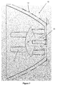
- The present disclosure includes an optical assembly configured to produce an integrated light emission pattern relative to a first plane with limited spread in imaginary planes perpendicular to the first plane. For purposes of this application, light emitted from an LED can be described as "narrow angle" light emitted at an angle of less than about 45° from the optical axis and "wide angle" light emitted at an angle of more than about 45° from the optical axis OA as shown in
Figure 6 . The initial trajectory of wide angle and narrow angle light may necessitate manipulation by different portions of a reflector and/or optical element to provide the desired illumination pattern. - A plurality of LEDs may be arranged on a support in a linear array, with the optical axes of the LEDs included in a first imaginary plane perpendicular to the support. An imaginary linear focal axis extends through the dies of the plurality of LEDs. Reflecting surfaces may extend along either side of the array, forming a concave reflective trough. The reflective trough may be generally defined by a parabolic curve having a focus coincident with the linear focal axis and projected along said axis to form a linear parabolic structure on which reflecting surfaces can be arranged. An elongated lens may be positioned above the LEDs and longitudinally bisected by the first imaginary plane. Preferably, the elongated lens and trough are configured so that light may not be emitted from the optical assembly without passing through the elongated lens or being redirected by the trough reflector. The elongated lens can be configured to redirect light emitted from the array of LEDs (and not incident upon the reflecting trough) from its emitted trajectory into imaginary planes parallel with the first plane. The reflective trough is preferably configured to redirect wide angle light (light not passing through the elongated lens) from a range of emitted trajectories into a range of reflected trajectories closer to the first plane. The redirection performed by the elongated lens may be described as "partially collimated" or "collimated with respect to the first plane." Such partially collimated light retains the component of its emitted trajectory within the imaginary planes into which it is redirected, whereas fully collimated light is parallel with a line such as the optical axis of an LED.
- Medial reflecting surfaces may also be positioned between adjacent pairs of LEDs, to redirect a portion of the wide angle light from each LED into imaginary planes perpendicular to the first imaginary plane containing the optical axes of the LEDs. This subset of wide angle light from each LED is partially collimated with respect to an imaginary plane perpendicular to the first plane and including the optical axis of the respective LED. Light reflected from the medial reflecting surfaces retains the component of its emitted trajectory within the imaginary planes into which it is redirected, however this light must be further redirected by the elongated lens or trough reflector before being emitted from the optical assembly. Thus, the subset of wide angle light incident upon the medial reflectors may be fully collimated with respect to the respective LED optical axis before exiting the optical assembly, depending upon the specific configuration of the elongated lens and trough reflector.
- Preferably, the shape of the medial reflecting surfaces is dictated by their function, e.g., redirecting this subset of wide angle light into trajectories having a smaller angular component with respect to imaginary planes perpendicular to both the first plane (containing the optical axes of the LEDs) and a second plane containing the light emitting dies of the LEDs. These planes may intersect at the linear focal axis of the assembly. It will be noted that the die of each LED typically includes a base that supports the light emitting die above a plane defined by a PC board upon which the LEDs are mounted. The imaginary second plane discussed in this application includes the LED dies and an imaginary linear focal axis passing through the LED dies. The medial reflecting surfaces may take many forms, but preferably comprise a convex surface when viewed looking toward the LED support (PC board). A preferred surface configuration for the medial reflecting surface partially collimates the subset of wide angle light incident upon the medial reflecting surfaces into imaginary planes substantially perpendicular to both the first plane containing the LED optical axes and the second plane passing through the LED dies. The medial reflecting surfaces may be defined by a segment of a parabola having a focus centered on the light emitting die of a respective LED. This parabolic segment is then rotated about the imaginary linear focal axis of the array to form a three dimensional surface. The medial reflecting surfaces on either side of a respective LED may be mirror images of each other and adjacent medial reflecting surfaces may meet at a semicircular peak. Other surface configurations approximating the intended function of the disclosed medial reflecting surfaces will occur to those skilled in the art. A semi-conical surface is an example of such an alternative configuration.
- In the absence of the medial reflecting surfaces, the subset of wide angle light redirected by the medial reflecting surfaces would continue on its emitted trajectory and be lost (absorbed or scattered) within the assembly or be partially collimated by the trough reflector and elongated lens (into imaginary planes parallel with the first plane containing the LED optical axes). In either case, the retained component of the emitted trajectory of this subset of wide angle light (within the imaginary planes) means it cannot contribute to a majority of desirable light emission patterns and is effectively wasted.
- The reflecting trough of the disclosed embodiment may be constructed from a plurality of reflecting surfaces, some of which are surfaces of rotation centered on the optical axis of an LED and others are linear surfaces defined by a curve projected along the length of the trough. Each surface is selected to re-direct light incident upon it into a range of trajectories that will contribute to a desired light emission pattern. The size and/or shape of each of the several reflecting surfaces may be adjusted to provide a desired light emission pattern.
- It is known in the field of optics that reflecting surfaces may be formed as an internal reflecting surface or as polished or metalized external surfaces. Both types of surfaces are intended to be encompassed in the appended claims.
- Referring to the drawings, wherein like numerals refer to like elements in the several Figures:
-
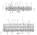
Figure 1 is a front plan view of an optical assembly according to aspects of the disclosure; -
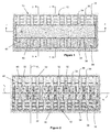
Figure 2 shows the trough reflector of the optical assembly ofFigure 1 with the longitudinal lens of the optical assembly removed for clarity; -
Figure 3 is an enlarged partial front plan view of the reflector of the optical assembly ofFigure 1 , showing LEDs in functional conjunction with the reflector medial reflecting surfaces; -
Figure 4 is longitudinal sectional view of the optical assembly ofFigure 1 , taken along line 4-4 thereof; -
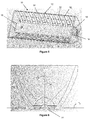
Figure 5 is a front perspective view of the warning signal light ofFigure 1 ; -
Figure 6 is an enlarged sectional view through an alternative optical assembly used to illustrate light emission from an exemplary LED; -
Figure 7 is an enlarged sectional view through the LED optical assembly ofFigure 1 , taken along line 7-7 thereof; -
Figure 8 is an enlarged left end view of the LED optical assembly ofFigure 1 ; -
Figure 9 is an enlarged sectional view of the optical assembly ofFigure 1 , taken along line 9-9 thereof; -
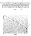
Figure 10 is a side plan view of the longitudinal lens of the optical assembly ofFigure 1 ; -
Figure 11 is an enlarged perspective view of the longitudinal lens of the optical assembly ofFigure 1 ; -
Figure 12 is a diagrammatic sectional view of the longitudinal lens of the optical assembly ofFigure 1 ; and -
Figures 13 - 15 are a diagrammatic sectional view of the longitudinal lens and one half of the trough reflector of the optical assembly ofFigure 1 . - LED optical assemblies will now be described with reference to the figures, in which common reference numerals are used to designate similar components.
Figures 1, 2, 4, 5,and 7-11 illustrate a first optical assembly according to aspects of the disclosure.Figures 3 and6 are used to illustrate exemplary LED light emitters in functional conjunction with portions of an optical assembly.Figures 12-16 are diagrams used to illustrate a preferred geometry of the optical assembly according to aspects of the present disclosure. The disclosed LED optical assemblies are suitable for use in emergency vehicle warning lights, but the disclosed optical assemblies may be appropriate for use in other warning and signaling apparatus as well as general illumination applications. - The disclosed
optical assembly 10 includes atrough reflector 12 and alongitudinal lens 14. As shown inFigures 1 ,4 ,5 ,7 and9 , thelens 14 extends the length of thetrough reflector 12.Projections 16 at either end of thelens 14 fit intocradle openings 18 at either end of thereflector 12. As best seen inFigures 4, 5, and 7-9 , thereflector 12 andlens 14 are configured to snap together, with theprojections 16 of thelongitudinal lens 14 received in thecradle openings 18. With reference toFigure 8 , eachcradle opening 18 is partially bounded by a pair ofshoulders 15 and aretention tab 17. As shown inFigures 4 ,5 ,8 ,10 and 11 , theprojections 16 at the ends of thelens 14 have a configuration complementary to theshoulders 15 andtab 17. Theprojection 16 at one end of thelens 14 is inserted into acradle opening 18 and advanced through the opening against the resilient movement of thetab 17. When oneprojection 16 of thelens 14 has moved through thecradle opening 18 sufficiently to permit theopposite projection 16 to enter thereflector trough 12, thelens 14 is pushed into the reflector trough until theprojection 16 bears on thetab 17 at the opposite end, which flexes to permit thelens projections 16 to be seated in theirrespective cradle openings 18 and held in place by thetabs 17. Theshoulders 15 support the lens from below, while thetabs 17 elastically retain thelens projections 15 in theirrespective cradle openings 18. The disclosedlens 14 also includes afastener receptacle 20, which also functions as a standoff to maintain the central portion of the length of thelongitudinal lens 14 in position above the array ofLEDs 22. Securing thelens 14 at both ends and in the middle helps prevent the lens from bowing away from the intended straight position under the influence of changing environmental conditions (temperature). In the disclosedoptical assembly 10, a fastener (not shown) extends through a heat sink and a PC board (not shown) to pull thereflector 12 andlens 14 into an installed position and maintain an efficient thermal contact between the PC board and the heat sink. - The
lens 14 includes a convexlight input surface 24 facing the LEDs and a convexlight emission surface 26 facing away from theLEDs 22. The convex curves defining thelight input surface 24 andlight emission surface 26 are projected along the length of thelens 14, resulting in a substantially constant sectional configuration. The geometry of thelens 14 is illustrated inFigure 12 , which is a sectional view of thelens 14 in operational position relative to anLED light source 22. Thelens 14 is configured to have a linear focus coincident with a linear focal axis AL passing through the dies of the plurality ofLEDs 22 as shown inFigure 2 .Input surface 24 is defined by an aspheric curve calculated according to Fermat's Principal, using the distance from theLED 22 and the refractive index of the lens material. With thelight input surface 24 configuration known, thelight emitting surface 26 is calculated to result in light from theLED 22 passing through thelens 14 being collimated into rays parallel with the optical axis of theLED 22. The resultinglight emitting surface 26 is defined by an elliptical curve as shown inFigure 12 . The upper and lower margins of thelens 14 are angled to permit light to pass above and below thelens 14 to be handled by the reflecting surfaces of thetrough reflector 12. If the light from an LED is incident upon thelight input surface 24, then it will be "partially collimated" into planes parallel with the optical axis AO and first plane P1, but will retain the angular component of its emission within those planes. The divergent portions of this light will enhance light emission to either side of the center of the optical arrangement parallel with plane P1. Other lens configurations will occur to those skilled in the art which will accomplish the function of partially collimating light from the LEDs and are compatible with the present disclosure. - The
reflector 12 in the disclosed embodiments includes parallel, mirror image reflecting surfaces extending along each side of the array ofLEDs 22. The function of the reflector is to redirect light originating from theLEDs 22 into a range of angles having trajectories close to planes parallel with plane P1 which includes the optical axes OA of theLEDs 22. Thetrough reflector 12 is generally defined by aparabola 28 having a focus at the die of theLED 22. The shape of thereflector 12 is modified by superimposing surfaces defined by other curves onto theparabola 28 as will be discussed below. The disclosed trough reflector includes at least four distinct reflecting surfaces, each handling different portions of the light from theLEDs 22 and producing a portion of the resulting light emission pattern. Medial reflectingsurfaces 30 are positioned to either side of eachLED 22 and centered on the linear focal axis AL. These surfaces are defined by portions ofparabola 28 rotated about the linear focal axis AL. The resulting surfaces of rotation redirect wide angle light from theLEDs 22 into planes such as P3 perpendicular to both the first plane P1 (containing the optical axes AO of the LEDs 22) and the second plane P2 (containing the light emitting dies of the LEDs 22). Other non-parabolic surfaces, such as conical surfaces may be used for the medial reflectingsurfaces 30 as will occur to those skilled in the art. Some of the light redirected by themedial reflecting surfaces 30 will subsequently pass through thelens 14, resulting in fully collimated light parallel with the optical axis AO of theLED 22. This fully collimated light reinforces the straight ahead or on axis peak light output from theoptical assembly 10. Light redirected by themedial reflecting surfaces 30 and not passing through thelens 14 will be incident upon thereflector 14. - The
trough reflector 12 has two mirror image parallel reflecting surfaces. Each of these surfaces includes three distinct reflecting portions. Rotatedportions 32 extend from the bottom to the top of the trough in a direction parallel with plane P3 as shown inFigure 2 . Rotatedportions 32 are arranged in pairs on opposite sides of eachLED 22. Each rotatedportion 32 is defined by a segment ofparabola 28 rotated about the optical axis AO of theLED 22 between the pair of rotatedportions 32. Thus, each rotatedportion 32 is a surface of rotation defined by a segment of a rotated parabola. Other curves rotated about the optical axis AO of theLED 22 may be compatible with the disclosed optical arrangement. This rotated surface configuration is designed to fully collimate divergent light incident upon it into a beam parallel with the optical axis AO of therespective LED 22. This light reinforces the on axis peak light output of theoptical assembly 10. The width W of theparabolic portions 32 coincides with the distance D between the medial reflecting surfaces 30.Parabolic portions 32 separate concave linear reflectingsurface portions trough reflector 12 from bottom to top. - Each of the linear reflecting
surface portions optical arrangement 10.Figures 13-15 illustrate the geometry of the elipses E1, E2 and E3, each of which has a first focus coincident with the light emitting die of the LED. Each elipse E1, E2, and E3 is positioned to be coincident with theparabola 28 at the bottom of each respectivelinear portion Figures 13-15 illustrates representative light rays originating at theLED 22 and incident upon the lower and upper margins of each respectivelinear portion - As shown in
Figures 2 and6 , the linear array ofLEDs 22 extends between the reflecting surfaces of thereflector 12. EachLED 22 emits light in a hemisphere surrounding its respective optical axis OA. Those skilled in the art will recognize that the emitted trajectory of some of the light from LEDs in the array will not reinforce a desirable light emission pattern for the assembly and is effectively wasted. In the disclosed warning light configuration, the light least likely to end up where it is useful is wide angle light emitted from each LED in a cone originating at the area of light emission (the LED die) and having a cone axis coincident with the linear focal axis AL of the assembly. There are two such cones of light for each LED in the assembly. Light incident upon the medial reflecting surfaces is emitted from the respective LED at an angle of at least 45° relative to the optical axis OA of the LED. The medial reflecting surfaces are positioned to redirect light having an emitted trajectory of less than approximately 40° from the linear focal axis AL of the LED array and at an emitted trajectory of greater than approximately 45° relative to the optical axis OA of eachrespective LED 22. It will be apparent that the cone of light is half a cone above the plane P2. - The medial reflectors are configured to redirect this light into trajectories that will contribute to the overall light emission pattern. Generally speaking, such redirected trajectories are those closer to the optical axis OA of the
respective LED 22 and/or further from the linear focal axis AL of the assembly. One disclosed configuration for the medial reflecting surface is defined by a parabolic curve having a focus at the area of LED light emission and rotated about the linear focal axis AL. Light incident upon themedial reflecting surfaces 30 is redirected into planes P3 perpendicular to both plane P2 and the plane P1 containing the optical axes OA of theLEDs 22. Light redirected by themedial reflecting surfaces 30 retains the component of its emitted trajectory within the planes P3 until passing through thelongitudinal lens 14 or being reflected by thetrough reflector 12. Light that is first redirected by the medial reflecting surfaces and then by thelongitudinal lens 14 is fully collimated (parallel) with respect to the optical axis of therespective LED 22. Thus light incident upon themedial reflecting surfaces 30 is incorporated into a desirable light emission pattern. - Those skilled in the art will recognize that a reflecting surface may be an external, polished or metalized surface or may be an internal surface of an optical solid, or so-called internal reflecting surface.
- While exemplary embodiments have been set forth for purposes of illustration, the foregoing description is by way of illustration and not limitation. Accordingly, various modifications, adaptations and further alternatives may occur to one of skill in the art without the exercise of invention.
Claims (9)
- An LED optical assembly (10) comprising:a plurality of light emitting diodes (LEDs) (22), each having an optical axis (OA) and a light emission pattern surrounding said optical axis (OA), said plurality of LEDs (22) being arranged in a linear array on a substantially planar support and provided with connections to electrical power, said linear array having a length and the optical axes of said plurality of LEDs (22) included in a first plane (P1) perpendicular to said planar support;a pair of longitudinal reflecting surfaces separated by said first plane (P1) and extending along opposite sides of said linear array, said longitudinal reflecting surfaces defining a trough having a generally parabolic sectional configuration and a linear focal axis (AL) passing through the light emitting dies of said LEDs (22) said trough including surfaces of rotation (32) extending from a bottom edge to a top edge of each said reflecting surface and defined by a curve rotated about the optical axis (OA) of each said LED (22) said trough including linear reflecting portions (34, 36, 38) defined by a curve projected along the linear focal axis (AL) said linear reflecting portions (34, 36, 38) alternating with said surfaces of rotation (32) whereby light emitted from said at least one LED (22) and incident upon said surfaces of rotation (32) is redirected into trajectories parallel with the optical axis (OA) of said at least one LED (22) and light incident upon said linear reflecting portions (34, 36, 38) is redirected into trajectories at an angle of less than 20° divergence from said first plane (P1).
- The LED optical assembly of claim 1, comprising a pair of medial reflecting surfaces intermediate said longitudinal reflecting surfaces, said medial reflecting surfaces disposed on opposite longitudinal sides of at least one said LED and configured to redirect light originating at said at least one said LED and incident upon said medial reflecting surfaces into planes perpendicular to both said support and said first plane, a portion of the light redirected by said medial reflecting surfaces being redirected by said longitudinal reflecting surfaces.
- The LED optical assembly of one of claims 1 or 2, wherein said longitudinal reflecting surfaces are mirror images of each other.
- The LED optical assembly of one of claims 1 to 3, wherein said medial reflecting surfaces are mirror images of each other.
- The LED optical assembly of one of claims 1 to 4, comprising a longitudinal lens extending the length of said linear array and configured to redirect light from said plurality of LEDs into planes parallel with said first plane.
- The LED optical assembly of claim 4, wherein light redirected by at least one of said medial reflecting surfaces and said longitudinal lens is collimated with respect to the optical axis of said at least one said LED.
- The LED optical assembly of claim 4 or 6, wherein said longitudinal reflecting surfaces are defined by a trough reflector having ends configured to receive and retain respective longitudinal ends of said longitudinal lens.
- The LED optical assembly of one of claims 1 to 7, wherein said linear reflecting portions are defined by segments of eliptical curves having a first focus at an area of light emission of said at least one said LED.
- The LED optical assembly of one of claims 1 to 8, wherein said linear reflecting portions comprise three linear reflecting portions, each said linear reflecting portion defined by a curve projected along said linear focal axis.
Applications Claiming Priority (1)
| Application Number | Priority Date | Filing Date | Title |
|---|---|---|---|
| US14/033,115 US9052088B2 (en) | 2013-09-20 | 2013-09-20 | Tuned composite optical arrangement for LED array |
Publications (2)
| Publication Number | Publication Date |
|---|---|
| EP2851613A1 EP2851613A1 (en) | 2015-03-25 |
| EP2851613B1 true EP2851613B1 (en) | 2016-07-27 |
Family
ID=51751886
Family Applications (1)
| Application Number | Title | Priority Date | Filing Date |
|---|---|---|---|
| EP14185145.1A Not-in-force EP2851613B1 (en) | 2013-09-20 | 2014-09-17 | Tuned composite optical arrangement for LED array |
Country Status (2)
| Country | Link |
|---|---|
| US (1) | US9052088B2 (en) |
| EP (1) | EP2851613B1 (en) |
Families Citing this family (1)
| Publication number | Priority date | Publication date | Assignee | Title |
|---|---|---|---|---|
| DE102013207609A1 (en) * | 2013-04-25 | 2014-10-30 | Osram Gmbh | Reflector arrangement with multiple reflectors and semiconductor light sources |
Family Cites Families (23)
| Publication number | Priority date | Publication date | Assignee | Title |
|---|---|---|---|---|
| US1235275A (en) | 1916-05-05 | 1917-07-31 | William H Wood | Lamp. |
| JPH10311944A (en) | 1997-05-14 | 1998-11-24 | Olympus Optical Co Ltd | Projecting device |
| US6641284B2 (en) | 2002-02-21 | 2003-11-04 | Whelen Engineering Company, Inc. | LED light assembly |
| US6644841B2 (en) | 2002-03-01 | 2003-11-11 | Gelcore Llc | Light emitting diode reflector |
| WO2004003428A1 (en) | 2002-06-20 | 2004-01-08 | Eveready Battery Company, Inc. | Led lighting device |
| US6851835B2 (en) | 2002-12-17 | 2005-02-08 | Whelen Engineering Company, Inc. | Large area shallow-depth full-fill LED light assembly |
| US6739738B1 (en) | 2003-01-28 | 2004-05-25 | Whelen Engineering Company, Inc. | Method and apparatus for light redistribution by internal reflection |
| US6758582B1 (en) | 2003-03-19 | 2004-07-06 | Elumina Technology Incorporation | LED lighting device |
| US7008079B2 (en) | 2003-11-21 | 2006-03-07 | Whelen Engineering Company, Inc. | Composite reflecting surface for linear LED array |
| US7175303B2 (en) | 2004-05-28 | 2007-02-13 | Alert Safety Lite Products Co., Inc | LED utility light |
| US7520650B2 (en) | 2004-06-28 | 2009-04-21 | Whelen Engineering Company, Inc. | Side-emitting collimator |
| US7083313B2 (en) | 2004-06-28 | 2006-08-01 | Whelen Engineering Company, Inc. | Side-emitting collimator |
| WO2006020687A1 (en) | 2004-08-10 | 2006-02-23 | Alert Safety Lite Products Co., Inc. | Led utility light |
| US7784969B2 (en) | 2006-04-12 | 2010-08-31 | Bhc Interim Funding Iii, L.P. | LED based light engine |
| US7677770B2 (en) | 2007-01-09 | 2010-03-16 | Lighting Science Group Corporation | Thermally-managed LED-based recessed down lights |
| US7690826B2 (en) | 2007-11-29 | 2010-04-06 | Sl Seobong | Adaptive front light system using LED headlamp |
| US8147081B2 (en) * | 2007-12-26 | 2012-04-03 | Lumination Llc | Directional linear light source |
| US9052083B2 (en) | 2008-10-31 | 2015-06-09 | Code 3, Inc. | Light fixture with inner and outer trough reflectors |
| US7959322B2 (en) | 2009-04-24 | 2011-06-14 | Whelen Engineering Company, Inc. | Optical system for LED array |
| US9388961B2 (en) | 2009-12-15 | 2016-07-12 | Whelen Engineering Compnay, Inc. | Asymmetrical optical system |
| RU2452059C1 (en) * | 2011-01-13 | 2012-05-27 | Закрытое Акционерное Общество "Научно-Производственная Коммерческая Фирма "Элтан Лтд" | Light-emitting diode source of white light with remote photoluminescent reflecting converter |
| US8485692B2 (en) * | 2011-09-09 | 2013-07-16 | Xicato, Inc. | LED-based light source with sharply defined field angle |
| US9488330B2 (en) * | 2012-04-23 | 2016-11-08 | Cree, Inc. | Direct aisle lighter |
-
2013
- 2013-09-20 US US14/033,115 patent/US9052088B2/en active Active
-
2014
- 2014-09-17 EP EP14185145.1A patent/EP2851613B1/en not_active Not-in-force
Also Published As
| Publication number | Publication date |
|---|---|
| US20150085479A1 (en) | 2015-03-26 |
| US9052088B2 (en) | 2015-06-09 |
| EP2851613A1 (en) | 2015-03-25 |
Similar Documents
| Publication | Publication Date | Title |
|---|---|---|
| US10352529B2 (en) | Collimating optic for LED illumination assembly having transverse slots on emission surface | |
| US10139079B2 (en) | LED illumination assembly with collimating optic | |
| US7712931B1 (en) | Sweep collimator | |
| US11378244B2 (en) | Headlight apparatus | |
| US9459436B2 (en) | Linear LED optical assembly for emitting collimated light | |
| US7520650B2 (en) | Side-emitting collimator | |
| US10295150B2 (en) | Asymmetrical optical system | |
| US7377671B2 (en) | Etendue-squeezing illumination optics | |
| US9157602B2 (en) | Optical element for a light source and lighting system using same | |
| US9388961B2 (en) | Asymmetrical optical system | |
| US9995872B2 (en) | Light mixing systems with a glass light pipe | |
| US20050286251A1 (en) | Side-emitting collimator | |
| EP2721656B1 (en) | Led light source | |
| US9074746B2 (en) | Non-uniform multi-faceted reflector for rear combination lamp providing sparkle effect | |
| US9528679B2 (en) | Wide angle optical system for LED array | |
| EP2726780B1 (en) | Light guide | |
| CA2905246C (en) | Optical system for a directional lamp | |
| US9052088B2 (en) | Tuned composite optical arrangement for LED array | |
| JP6689590B2 (en) | Light flux control member, light emitting device, and lighting device | |
| JP5314639B2 (en) | Vehicle lighting | |
| JP6405060B2 (en) | Tubular light emitting device | |
| EP2843301A1 (en) | Light engine for an illumination device | |
| WO2019126004A1 (en) | Beam forming optic for led |
Legal Events
| Date | Code | Title | Description |
|---|---|---|---|
| PUAI | Public reference made under article 153(3) epc to a published international application that has entered the european phase |
Free format text: ORIGINAL CODE: 0009012 |
|
| 17P | Request for examination filed |
Effective date: 20140917 |
|
| AK | Designated contracting states |
Kind code of ref document: A1 Designated state(s): AL AT BE BG CH CY CZ DE DK EE ES FI FR GB GR HR HU IE IS IT LI LT LU LV MC MK MT NL NO PL PT RO RS SE SI SK SM TR |
|
| AX | Request for extension of the european patent |
Extension state: BA ME |
|
| R17P | Request for examination filed (corrected) |
Effective date: 20150907 |
|
| RBV | Designated contracting states (corrected) |
Designated state(s): AL AT BE BG CH CY CZ DE DK EE ES FI FR GB GR HR HU IE IS IT LI LT LU LV MC MK MT NL NO PL PT RO RS SE SI SK SM TR |
|
| GRAP | Despatch of communication of intention to grant a patent |
Free format text: ORIGINAL CODE: EPIDOSNIGR1 |
|
| RIC1 | Information provided on ipc code assigned before grant |
Ipc: F21V 7/08 20060101ALI20160129BHEP Ipc: F21Y 115/10 20160101ALN20160129BHEP Ipc: F21V 7/06 20060101AFI20160129BHEP Ipc: F21V 7/09 20060101ALI20160129BHEP Ipc: F21V 5/04 20060101ALI20160129BHEP Ipc: F21Y 103/10 20160101ALN20160129BHEP Ipc: F21V 13/04 20060101ALI20160129BHEP |
|
| RIC1 | Information provided on ipc code assigned before grant |
Ipc: F21V 5/04 20060101ALI20160209BHEP Ipc: F21V 7/09 20060101ALI20160209BHEP Ipc: F21Y 103/10 20160101ALN20160209BHEP Ipc: F21Y 115/10 20160101ALN20160209BHEP Ipc: F21V 7/08 20060101ALI20160209BHEP Ipc: F21V 7/06 20060101AFI20160209BHEP Ipc: F21V 13/04 20060101ALI20160209BHEP |
|
| INTG | Intention to grant announced |
Effective date: 20160304 |
|
| RIC1 | Information provided on ipc code assigned before grant |
Ipc: F21V 5/04 20060101ALI20160225BHEP Ipc: F21V 7/08 20060101ALI20160225BHEP Ipc: F21V 13/04 20060101ALI20160225BHEP Ipc: F21Y 103/10 20160101ALN20160225BHEP Ipc: F21V 7/09 20060101ALI20160225BHEP Ipc: F21V 7/06 20060101AFI20160225BHEP Ipc: F21Y 115/10 20160101ALN20160225BHEP |
|
| GRAS | Grant fee paid |
Free format text: ORIGINAL CODE: EPIDOSNIGR3 |
|
| GRAA | (expected) grant |
Free format text: ORIGINAL CODE: 0009210 |
|
| AK | Designated contracting states |
Kind code of ref document: B1 Designated state(s): AL AT BE BG CH CY CZ DE DK EE ES FI FR GB GR HR HU IE IS IT LI LT LU LV MC MK MT NL NO PL PT RO RS SE SI SK SM TR |
|
| REG | Reference to a national code |
Ref country code: GB Ref legal event code: FG4D |
|
| REG | Reference to a national code |
Ref country code: CH Ref legal event code: EP |
|
| REG | Reference to a national code |
Ref country code: AT Ref legal event code: REF Ref document number: 816105 Country of ref document: AT Kind code of ref document: T Effective date: 20160815 |
|
| REG | Reference to a national code |
Ref country code: IE Ref legal event code: FG4D |
|
| REG | Reference to a national code |
Ref country code: DE Ref legal event code: R096 Ref document number: 602014002864 Country of ref document: DE |
|
| REG | Reference to a national code |
Ref country code: LT Ref legal event code: MG4D |
|
| REG | Reference to a national code |
Ref country code: NL Ref legal event code: MP Effective date: 20160727 |
|
| REG | Reference to a national code |
Ref country code: AT Ref legal event code: MK05 Ref document number: 816105 Country of ref document: AT Kind code of ref document: T Effective date: 20160727 |
|
| PG25 | Lapsed in a contracting state [announced via postgrant information from national office to epo] |
Ref country code: NL Free format text: LAPSE BECAUSE OF FAILURE TO SUBMIT A TRANSLATION OF THE DESCRIPTION OR TO PAY THE FEE WITHIN THE PRESCRIBED TIME-LIMIT Effective date: 20160727 Ref country code: HR Free format text: LAPSE BECAUSE OF FAILURE TO SUBMIT A TRANSLATION OF THE DESCRIPTION OR TO PAY THE FEE WITHIN THE PRESCRIBED TIME-LIMIT Effective date: 20160727 Ref country code: IS Free format text: LAPSE BECAUSE OF FAILURE TO SUBMIT A TRANSLATION OF THE DESCRIPTION OR TO PAY THE FEE WITHIN THE PRESCRIBED TIME-LIMIT Effective date: 20161127 Ref country code: NO Free format text: LAPSE BECAUSE OF FAILURE TO SUBMIT A TRANSLATION OF THE DESCRIPTION OR TO PAY THE FEE WITHIN THE PRESCRIBED TIME-LIMIT Effective date: 20161027 Ref country code: FI Free format text: LAPSE BECAUSE OF FAILURE TO SUBMIT A TRANSLATION OF THE DESCRIPTION OR TO PAY THE FEE WITHIN THE PRESCRIBED TIME-LIMIT Effective date: 20160727 Ref country code: LT Free format text: LAPSE BECAUSE OF FAILURE TO SUBMIT A TRANSLATION OF THE DESCRIPTION OR TO PAY THE FEE WITHIN THE PRESCRIBED TIME-LIMIT Effective date: 20160727 Ref country code: IT Free format text: LAPSE BECAUSE OF FAILURE TO SUBMIT A TRANSLATION OF THE DESCRIPTION OR TO PAY THE FEE WITHIN THE PRESCRIBED TIME-LIMIT Effective date: 20160727 Ref country code: RS Free format text: LAPSE BECAUSE OF FAILURE TO SUBMIT A TRANSLATION OF THE DESCRIPTION OR TO PAY THE FEE WITHIN THE PRESCRIBED TIME-LIMIT Effective date: 20160727 |
|
| PG25 | Lapsed in a contracting state [announced via postgrant information from national office to epo] |
Ref country code: GR Free format text: LAPSE BECAUSE OF FAILURE TO SUBMIT A TRANSLATION OF THE DESCRIPTION OR TO PAY THE FEE WITHIN THE PRESCRIBED TIME-LIMIT Effective date: 20161028 Ref country code: AT Free format text: LAPSE BECAUSE OF FAILURE TO SUBMIT A TRANSLATION OF THE DESCRIPTION OR TO PAY THE FEE WITHIN THE PRESCRIBED TIME-LIMIT Effective date: 20160727 Ref country code: LV Free format text: LAPSE BECAUSE OF FAILURE TO SUBMIT A TRANSLATION OF THE DESCRIPTION OR TO PAY THE FEE WITHIN THE PRESCRIBED TIME-LIMIT Effective date: 20160727 Ref country code: ES Free format text: LAPSE BECAUSE OF FAILURE TO SUBMIT A TRANSLATION OF THE DESCRIPTION OR TO PAY THE FEE WITHIN THE PRESCRIBED TIME-LIMIT Effective date: 20160727 Ref country code: PT Free format text: LAPSE BECAUSE OF FAILURE TO SUBMIT A TRANSLATION OF THE DESCRIPTION OR TO PAY THE FEE WITHIN THE PRESCRIBED TIME-LIMIT Effective date: 20161128 Ref country code: BE Free format text: LAPSE BECAUSE OF NON-PAYMENT OF DUE FEES Effective date: 20160727 Ref country code: SE Free format text: LAPSE BECAUSE OF FAILURE TO SUBMIT A TRANSLATION OF THE DESCRIPTION OR TO PAY THE FEE WITHIN THE PRESCRIBED TIME-LIMIT Effective date: 20160727 Ref country code: PL Free format text: LAPSE BECAUSE OF FAILURE TO SUBMIT A TRANSLATION OF THE DESCRIPTION OR TO PAY THE FEE WITHIN THE PRESCRIBED TIME-LIMIT Effective date: 20160727 |
|
| REG | Reference to a national code |
Ref country code: DE Ref legal event code: R119 Ref document number: 602014002864 Country of ref document: DE |
|
| PG25 | Lapsed in a contracting state [announced via postgrant information from national office to epo] |
Ref country code: MC Free format text: LAPSE BECAUSE OF FAILURE TO SUBMIT A TRANSLATION OF THE DESCRIPTION OR TO PAY THE FEE WITHIN THE PRESCRIBED TIME-LIMIT Effective date: 20160727 Ref country code: RO Free format text: LAPSE BECAUSE OF FAILURE TO SUBMIT A TRANSLATION OF THE DESCRIPTION OR TO PAY THE FEE WITHIN THE PRESCRIBED TIME-LIMIT Effective date: 20160727 Ref country code: EE Free format text: LAPSE BECAUSE OF FAILURE TO SUBMIT A TRANSLATION OF THE DESCRIPTION OR TO PAY THE FEE WITHIN THE PRESCRIBED TIME-LIMIT Effective date: 20160727 |
|
| PG25 | Lapsed in a contracting state [announced via postgrant information from national office to epo] |
Ref country code: SK Free format text: LAPSE BECAUSE OF FAILURE TO SUBMIT A TRANSLATION OF THE DESCRIPTION OR TO PAY THE FEE WITHIN THE PRESCRIBED TIME-LIMIT Effective date: 20160727 Ref country code: DK Free format text: LAPSE BECAUSE OF FAILURE TO SUBMIT A TRANSLATION OF THE DESCRIPTION OR TO PAY THE FEE WITHIN THE PRESCRIBED TIME-LIMIT Effective date: 20160727 Ref country code: CZ Free format text: LAPSE BECAUSE OF FAILURE TO SUBMIT A TRANSLATION OF THE DESCRIPTION OR TO PAY THE FEE WITHIN THE PRESCRIBED TIME-LIMIT Effective date: 20160727 Ref country code: BG Free format text: LAPSE BECAUSE OF FAILURE TO SUBMIT A TRANSLATION OF THE DESCRIPTION OR TO PAY THE FEE WITHIN THE PRESCRIBED TIME-LIMIT Effective date: 20161027 Ref country code: SM Free format text: LAPSE BECAUSE OF FAILURE TO SUBMIT A TRANSLATION OF THE DESCRIPTION OR TO PAY THE FEE WITHIN THE PRESCRIBED TIME-LIMIT Effective date: 20160727 |
|
| PLBE | No opposition filed within time limit |
Free format text: ORIGINAL CODE: 0009261 |
|
| STAA | Information on the status of an ep patent application or granted ep patent |
Free format text: STATUS: NO OPPOSITION FILED WITHIN TIME LIMIT |
|
| REG | Reference to a national code |
Ref country code: IE Ref legal event code: MM4A |
|
| REG | Reference to a national code |
Ref country code: FR Ref legal event code: ST Effective date: 20170531 |
|
| 26N | No opposition filed |
Effective date: 20170502 |
|
| PG25 | Lapsed in a contracting state [announced via postgrant information from national office to epo] |
Ref country code: DE Free format text: LAPSE BECAUSE OF NON-PAYMENT OF DUE FEES Effective date: 20170401 Ref country code: IE Free format text: LAPSE BECAUSE OF NON-PAYMENT OF DUE FEES Effective date: 20160917 Ref country code: FR Free format text: LAPSE BECAUSE OF NON-PAYMENT OF DUE FEES Effective date: 20160930 |
|
| PG25 | Lapsed in a contracting state [announced via postgrant information from national office to epo] |
Ref country code: LU Free format text: LAPSE BECAUSE OF NON-PAYMENT OF DUE FEES Effective date: 20160917 Ref country code: SI Free format text: LAPSE BECAUSE OF FAILURE TO SUBMIT A TRANSLATION OF THE DESCRIPTION OR TO PAY THE FEE WITHIN THE PRESCRIBED TIME-LIMIT Effective date: 20160727 |
|
| REG | Reference to a national code |
Ref country code: CH Ref legal event code: PL |
|
| PG25 | Lapsed in a contracting state [announced via postgrant information from national office to epo] |
Ref country code: HU Free format text: LAPSE BECAUSE OF FAILURE TO SUBMIT A TRANSLATION OF THE DESCRIPTION OR TO PAY THE FEE WITHIN THE PRESCRIBED TIME-LIMIT; INVALID AB INITIO Effective date: 20140917 |
|
| PG25 | Lapsed in a contracting state [announced via postgrant information from national office to epo] |
Ref country code: MT Free format text: LAPSE BECAUSE OF NON-PAYMENT OF DUE FEES Effective date: 20160930 Ref country code: CY Free format text: LAPSE BECAUSE OF FAILURE TO SUBMIT A TRANSLATION OF THE DESCRIPTION OR TO PAY THE FEE WITHIN THE PRESCRIBED TIME-LIMIT Effective date: 20160727 Ref country code: MK Free format text: LAPSE BECAUSE OF FAILURE TO SUBMIT A TRANSLATION OF THE DESCRIPTION OR TO PAY THE FEE WITHIN THE PRESCRIBED TIME-LIMIT Effective date: 20160727 |
|
| PG25 | Lapsed in a contracting state [announced via postgrant information from national office to epo] |
Ref country code: LI Free format text: LAPSE BECAUSE OF NON-PAYMENT OF DUE FEES Effective date: 20170930 Ref country code: CH Free format text: LAPSE BECAUSE OF NON-PAYMENT OF DUE FEES Effective date: 20170930 |
|
| PG25 | Lapsed in a contracting state [announced via postgrant information from national office to epo] |
Ref country code: AL Free format text: LAPSE BECAUSE OF FAILURE TO SUBMIT A TRANSLATION OF THE DESCRIPTION OR TO PAY THE FEE WITHIN THE PRESCRIBED TIME-LIMIT Effective date: 20160727 Ref country code: TR Free format text: LAPSE BECAUSE OF FAILURE TO SUBMIT A TRANSLATION OF THE DESCRIPTION OR TO PAY THE FEE WITHIN THE PRESCRIBED TIME-LIMIT Effective date: 20160727 |
|
| GBPC | Gb: european patent ceased through non-payment of renewal fee |
Effective date: 20180917 |
|
| PG25 | Lapsed in a contracting state [announced via postgrant information from national office to epo] |
Ref country code: GB Free format text: LAPSE BECAUSE OF NON-PAYMENT OF DUE FEES Effective date: 20180917 |