EP2851268A1 - Power steering system, vehicle equipped with same, and control method thereof - Google Patents
Power steering system, vehicle equipped with same, and control method thereof Download PDFInfo
- Publication number
- EP2851268A1 EP2851268A1 EP13791657.3A EP13791657A EP2851268A1 EP 2851268 A1 EP2851268 A1 EP 2851268A1 EP 13791657 A EP13791657 A EP 13791657A EP 2851268 A1 EP2851268 A1 EP 2851268A1
- Authority
- EP
- European Patent Office
- Prior art keywords
- slope
- steering
- rotation speed
- vehicle
- electric pump
- Prior art date
- Legal status (The legal status is an assumption and is not a legal conclusion. Google has not performed a legal analysis and makes no representation as to the accuracy of the status listed.)
- Granted
Links
Images



Classifications
-
- B—PERFORMING OPERATIONS; TRANSPORTING
- B62—LAND VEHICLES FOR TRAVELLING OTHERWISE THAN ON RAILS
- B62D—MOTOR VEHICLES; TRAILERS
- B62D5/00—Power-assisted or power-driven steering
- B62D5/06—Power-assisted or power-driven steering fluid, i.e. using a pressurised fluid for most or all the force required for steering a vehicle
- B62D5/065—Power-assisted or power-driven steering fluid, i.e. using a pressurised fluid for most or all the force required for steering a vehicle characterised by specially adapted means for varying pressurised fluid supply based on need, e.g. on-demand, variable assist
-
- B—PERFORMING OPERATIONS; TRANSPORTING
- B62—LAND VEHICLES FOR TRAVELLING OTHERWISE THAN ON RAILS
- B62D—MOTOR VEHICLES; TRAILERS
- B62D15/00—Steering not otherwise provided for
- B62D15/02—Steering position indicators ; Steering position determination; Steering aids
- B62D15/025—Active steering aids, e.g. helping the driver by actively influencing the steering system after environment evaluation
-
- B—PERFORMING OPERATIONS; TRANSPORTING
- B62—LAND VEHICLES FOR TRAVELLING OTHERWISE THAN ON RAILS
- B62D—MOTOR VEHICLES; TRAILERS
- B62D15/00—Steering not otherwise provided for
- B62D15/02—Steering position indicators ; Steering position determination; Steering aids
- B62D15/029—Steering assistants using warnings or proposing actions to the driver without influencing the steering system
-
- B—PERFORMING OPERATIONS; TRANSPORTING
- B62—LAND VEHICLES FOR TRAVELLING OTHERWISE THAN ON RAILS
- B62D—MOTOR VEHICLES; TRAILERS
- B62D5/00—Power-assisted or power-driven steering
- B62D5/06—Power-assisted or power-driven steering fluid, i.e. using a pressurised fluid for most or all the force required for steering a vehicle
- B62D5/062—Details, component parts
- B62D5/064—Pump driven independently from vehicle engine, e.g. electric driven pump
-
- B—PERFORMING OPERATIONS; TRANSPORTING
- B62—LAND VEHICLES FOR TRAVELLING OTHERWISE THAN ON RAILS
- B62D—MOTOR VEHICLES; TRAILERS
- B62D6/00—Arrangements for automatically controlling steering depending on driving conditions sensed and responded to, e.g. control circuits
-
- B—PERFORMING OPERATIONS; TRANSPORTING
- B62—LAND VEHICLES FOR TRAVELLING OTHERWISE THAN ON RAILS
- B62D—MOTOR VEHICLES; TRAILERS
- B62D6/00—Arrangements for automatically controlling steering depending on driving conditions sensed and responded to, e.g. control circuits
- B62D6/007—Arrangements for automatically controlling steering depending on driving conditions sensed and responded to, e.g. control circuits adjustable by the driver, e.g. sport mode
Definitions
- the present invention relates to a power steering system which supplies hydraulic oil with an electric pump to assist a steering operation, a vehicle equipped with the power steering system, and a control method of the power steering system.
- a power steering system is one of such systems.
- the power steering system makes driving of a vehicle comfortable and makes driving operations easy and accurate.
- Such power steering systems include an electric power steering system (hereafter, referred to as EPS system) which directly assists the steering operation with a motor (electric motor), an electro-hydraulic power steering system (hereafter, referred to as EHPS system) which assists the steering operation by supplying hydraulic pressure with an electric pump, and the like.
- EPS system electric power steering system
- EHPS system electro-hydraulic power steering system
- the EHPS system can provide operation feeling similar to that of a conventional hydraulic power steering system and is thus often provided in heavy-weight vehicles such as trucks.
- an EHPS system 10 includes an electric pump 11 having a hydraulic pump 11a and a motor (electric motor) 11b, a reserve tank 12, a power steering unit 13 (steering assisting device) 13, a relief valve (line pressure control valve) 14, and a check valve 15.
- the control of the EHPS system 10 is control of increasing and decreasing assisting force of the power steering unit 13 by supplying fluid (hydraulic oil) from the electric pump 11 to the power steering unit 13. It is possible to reduce energy consumed by the electric pump 11 by causing the electric pump 11 to supply the fluid when the assisting force of the power steering unit 13 is required and by stopping the supply of fluid when the assisting force is unnecessary, i.e. when the steering wheel is at a neutral position in the steering operation.
- fluid hydroaulic oil
- the supply amount of fluid is set to zero, there is a risk of a seizure phenomenon occurring in the power steering unit 13, a wobbling phenomenon of the steering wheel occurring due to disturbance such as kickback in straight travelling, or a similar phenomenon occurring. Furthermore, setting the supply amount to zero has a problem that, in abrupt steering or the like, a long time is required for the supply amount of fluid to increase, and response delay occurs in the steering operation assist. In view of this, in cases such as where no steering operation is required, the electric pump 11 is controlled to supply the fluid to the power steering unit 13 at a minimum required standby flow rate.
- a standby rotation speed N0 (rpm) of the electric pump 11 corresponding to the vehicle speed Vn (km/h) is basically defined by using a standby rotation speed map M1.
- the rotation speed of the electric pump 11 is controlled to reach the standby rotation speed N0.
- a vehicle speed coefficient (also referred to as vehicle speed responsiveness) k corresponding to the vehicle speed Vn is calculated from a vehicle speed coefficient map M2.
- an additional rotation speed N1 (rpm) corresponding to a steering speed ⁇ n (deg/s) is calculated from a steering speed sense map M3.
- the calculated vehicle speed coefficient k and the calculated additional rotation speed N1 are multiplied by each other, and a steering correction value N1' (rpm) is thereby calculated.
- the standby rotation speed N0 and the steering correction value N1' are added to each other, and a target rotation speed N2 (rpm) is thereby calculated.
- the rotation speed of the electric pump 11 is controlled to reach the target rotation speed N2.
- the aforementioned control method has a problem that, when the vehicle is travelling on a slope, the steering force is insufficient in slope descent due to increase in a front axle load and steering is difficult.
- the aforementioned control method also has a problem that steering force is excessive in slope ascent and feeling of response is lost.
- the standby rotation speed N0 is increased to overcome the problem of insufficient steering force in slope descent for example, the electric energy of the electric pump 11 increases and the fuel consumption deteriorates. Moreover, the increase of the standby rotation speed N0 leads to increase of excessive steering force in slope ascent. Meanwhile, if the standby rotation speed N0 is reduced to overcome the problem of excessive steering force in slope ascent, the steering operation becomes difficult or impossible in slope descent due to insufficient steering force.
- a front axle load which is the greatest factor of steering force changes greatly due to a short wheelbase and increase in the height of the center of gravity which is caused by loading of cargo. Accordingly, there occurs jerky feeling in the steering operation due to insufficient steering force in slope descent and lack of response in the steering operation due to excessive steering force in slope ascent.
- the assist force in the steering operation needs to be increased and decreased according to the gradient of a road surface and there is a need to consider control according to the gradient of the road surface.
- Patent Document 1 Japanese patent application Kokai publication No. Hei 5-221330
- the present invention has been made in view of the problems described above and an object thereof is to provide a power steering system which can suppress both of jerky feeling in a steering operation due to insufficient steering force in slope descent of a vehicle and lack of response in the steering operation due to excessive steering force in slope ascent of the vehicle, a vehicle equipped with the power steering system, and a control method of the power steering system.
- a power steering system of the present invention for solving the problems described above is a power steering system including: an electric pump configured to supply hydraulic oil to a steering assisting device configured to assist a steering performance of a steering wheel; and a control device configured to control a supply amount of the hydraulic oil by means of a rotation speed of the electric pump, wherein the control device includes first control means to calculate an on-slope standby rotation speed and to control the electric pump such that the electric pump is set to the on-slope standby rotation speed, when a vehicle is descending or ascending a slope, the on-slope standby rotation speed calculated by correcting a standby rotation speed of the electric pump corresponding to a vehicle speed with a slope correction value calculated according to a slope angle or a vehicle body angle.
- This configuration can suppress both of jerky feeling in the steering operation due to insufficient steering force in slope descent and lack of response in the steering operation due to excessive steering force in slope ascent.
- This configuration is suitable particularly for a cab-over truck in which a front axle load changes greatly due to a short wheelbase and a high center of gravity resulting from loading of cargo.
- controlling the standby rotation speed of the electric pump according to the slope angle or the vehicle body angle can suppress pump drive loss and improve fuel consumption by reducing the pump drive loss without electric power consumed in a normal state being increased.
- the slope angle or the vehicle body angle mentioned herein is a value inferred by using an arc-cosine.
- the slope angle or the vehicle body angle is a detection value directly detected by the angle sensor.
- the slope angle or the vehicle body angle takes a negative value when the vehicle is descending a slope, and takes a positive value when the vehicle is ascending a slope.
- the control device may include second control means to calculate a steering target rotation speed and to control the electric pump such that the electric pump is set to the steering target rotation speed, when the steering wheel is steered after control of the first means, the steering target rotation speed calculated by correcting the on-slope standby rotation speed with a steering correction value corresponding to at least steering of the steering wheel.
- the electric pump is controlled to be set to the on-slope standby rotation speed corresponding to the slope angle or the vehicle body angle as described above when the vehicle is descending or ascending a slope, and the on-slope standby rotation speed is corrected according to the steering of the steering wheel. Accordingly, it is possible to achieve a good balance between responsiveness in the steering of the steering wheel in slope descent and a turning performance in slope ascent, without the responsiveness being deteriorated.
- control device may include a slope correction value map storing the slope correction value based on the slope angle or the vehicle body angle
- the first control means may include means for: calculating the slope correction value from the slope correction value map, according to the slope angle or the vehicle body angle; and increasing the standby rotation speed by the slope correcting value when the slope angle or the vehicle body angle indicates slope descent and decreasing the standby rotation speed by the slope correction value when the slope angle or the vehicle body angle indicates slope ascent.
- the change in the front axle load is not affected or only slightly affected by a vehicle speed coefficient (vehicle speed responsiveness) and a steering speed. Accordingly, in order to suppress the effect of the front axle load change on the steering operation, increasing and decreasing the standby rotation speed corresponding to the vehicle speed has a great effect.
- vehicle speed coefficient vehicle speed responsiveness
- a vehicle for solving the problems described above is configured to be equipped with the aforementioned power steering system.
- This configuration can suppress both of jerky feeling in the steering operation due to insufficient steering force in slope descent and lack of response in the steering operation due to excessive steering force in slope ascent.
- the configuration is suitable for a so-called cab-over truck being a truck which has a short wheelbase and a high center of gravity and whose load becomes heavier when loaded with cargo.
- a control method of a power steering system for solving the problems described above is a control method of a power steering system including an electric pump configured to supply hydraulic oil to a steering assisting device configured to assist a steering performance of a steering wheel, characterized in that the method of comprises controlling a supply amount of the hydraulic oil by driving the electric pump such that the electric pump is set to an on-slope standby rotation speed, when a vehicle is descending or ascending a slope, the on-slope standby rotation speed calculated by correcting a standby rotation speed calculated according to a vehicle speed with a slope correction value calculated according to a slope angle or a vehicle body angle.
- the standby rotation speed of the electric pump is not changed when the vehicle is horizontal (when the vehicle is not descending or ascending a slope), and is changed according to increase and decrease of the slope angle or the vehicle body angle when the vehicle is descending or ascending a slope. Accordingly, for example, it is possible to simultaneously solve the problem of insufficient steering force in slope descent and the problem of excessive steering force in slope ascent which occur in a cab-over truck.
- the present invention can suppress both of jerky feeling in the steering operation due to insufficient steering force in slope descent and lack of response in the steering operation due to excessive steering force in slope ascent. Moreover, since the standby rotation speed of the electric pump in the normal state is not changed, it is possible to reduce pump loss and improve fuel consumption.
- FIG. 1 A power steering system in an embodiment of the present invention, a vehicle equipped with the power steering system, and a control method of the power steering system are described below by referring to the drawings.
- description is given of the vehicle equipped with the power steering system in the embodiment of the present invention by referring to Fig. 1 .
- illustration is such that an upper side of Fig. 1 is a front side of the vehicle and a lower side of Fig. 1 is a rear side of the vehicle.
- a so-called cab-over truck including a body 1a, a cab 1b, and a chassis 1c, as an example of the vehicle 1 of the embodiment. Since this cab-over truck has a short wheelbase and a high center of gravity, load transfer to front wheels is great, and the present invention is thus particularly effective when applied to the cab-over truck. However, the present invention can be also applied to a normal bonnet-type vehicle.
- the vehicle 1 transmits drive force generated in a power plant 2 to a drive shaft 3 and travels by using rear wheels 9c and 9d (not illustrated) as drive wheels, the power plant 2 being formed of an engine (internal combustion engine) 2a, a clutch (drive force transmitting device) 2b, a transmission (gear shifting device) 2c, a crankshaft 2d, an alternator (power generator) 2e, and a cooling device (a radiator, a fan, and the like) 2f.
- an engine internal combustion engine
- a clutch drive force transmitting device
- a transmission gear shifting device
- crankshaft 2d a crankshaft 2d
- an alternator power generator
- a cooling device a radiator, a fan, and the like
- the vehicle 1 also includes a steering device 4 formed of a steering wheel (also referred to as hand wheel) 4a and foot pedals (an accelerator pedal, a brake pedal, a clutch pedal, and the like) 4b, an ECU (control device) 5 called engine control unit, a steering angle sensor 6, a vehicle speed sensor 7, and an acceleration sensor (G sensor) 8.
- a steering device 4 formed of a steering wheel (also referred to as hand wheel) 4a and foot pedals (an accelerator pedal, a brake pedal, a clutch pedal, and the like) 4b, an ECU (control device) 5 called engine control unit, a steering angle sensor 6, a vehicle speed sensor 7, and an acceleration sensor (G sensor) 8.
- the vehicle 1 includes an EHPS system (electro-hydraulic power steering system) 10 which operates in conjunction with the steering wheel 4a and assists the steering wheel 4a in steering of front wheels 9a and 9b.
- EHPS system electronic-hydraulic power steering system
- the present invention can be applied to a rear-wheel steering vehicle and a four-wheel steering vehicle.
- the ECU 5 is a micro controller which performs overall electric control and which handles control of the power plant 2 on the basis of information from the steering device 4 and the sensors 6 to 8 by using an electric circuit.
- a device for the control of the power plant 2 and a device for the control of the power steering system 10 may be provided separately.
- W refers to the weight of vehicle 1
- G refers to the center of gravity of the vehicle 1
- h refers to the height of the center of gravity (the height of the center of gravity G from the slope)
- ⁇ refers to the slope angle
- S refers to the wheelbase (distance between a front axle and a rear axle)
- a refers to the distance from the center of gravity to the front axle
- b refers to the distance from the center of gravity to the rear axle
- bold lines in the drawing show action of force.
- a front axle load Rf1 in slope descent of the vehicle 1 can be expressed by the following math (1).
- Rf ⁇ 1 W cos ⁇ ⁇ b S + W sin ⁇ ⁇ h S
- loading cargo on the body 1a further increases the height h of the center of gravity, the load transfer from the front wheels 9a and 9b becomes even greater.
- the proportion of the distances a and b in the wheelbase S is such that a ⁇ b is satisfied, the change of the front axle load is great when the vehicle 1 travels on a slope.
- a front axle load Rf2 (not illustrated) in slope ascent of the vehicle 1 can be expressed by the following math (2).
- Rf ⁇ 2 W cos ⁇ ⁇ b S - W sin ⁇ ⁇ h S
- a control method of the power steering system 10 of the present invention is described with reference to Figs. 3 and 4 .
- a value calculated by the ECU 5 from a signal detected by the steering angle sensor 6 is referred to as steering speed ⁇ n (deg/s)
- a value calculated by the ECU 5 from a signal detected by the vehicle speed sensor 7 is referred to as vehicle speed Vn (km/h)
- vehicle body angle ⁇ n (deg) a value calculated by the ECU 5 from a signal detected by the G sensor 8 .
- the control method of the power steering system 10 in the embodiment of the present invention is a method in which a standby rotation speed N0 of the system control method shown in Fig. 6 is increased and decreased according to the vehicle body angle ⁇ n before the standby rotation speed N0 and a steering correction value N1' are added to each other.
- this control method includes a first step S10 in which an electric pump 11 supplies a standby fluid (hydraulic oil) to a power steering unit 13 when steering of the steering wheel 4a is unnecessary (when the steering wheel 4a is at a neutral position) and a second step S20 in which the electric pump 11 supplies assisting fluid to the power steering unit 13 when the steering wheel 4a is steered and the power steering unit 13 assists the steering of the steering wheel 4a.
- a standby fluid hydroaulic oil
- the first step S10 is started.
- the vehicle speed sensor 7 detects the vehicle speed Vn of the vehicle 1 (step S1)
- a standby rotation speed map M1 specifying the standby rotation speed N0 based on the vehicle speed Vn is referred and the standby rotation speed N0 corresponding to the vehicle speed Vn is thereby calculated (step S2).
- the rotation speed of the electric pump 11 is controlled to reach the calculated standby rotation speed N0 (step S3).
- the G sensor 8 detects the vehicle body angle ⁇ n which is inclined in a slope (step S4).
- the G sensor 8 is installed to detect only the acceleration in a vehicle body vertical direction of the vehicle 1, the detection value of the G sensor 8 decreases according to the slope angle ⁇ .
- a slope correction value map M4 specifying a slope correction value Nx based on the vehicle body angle ⁇ n is referred and the slope correction value Nx corresponding to the detected vehicle body angle ⁇ n is thereby calculated (step S5) .
- the calculated slope correction value Nx is added to the standby rotation speed N0 and the on-slope standby rotation speed N0' is thereby calculated (step S6).
- the slope correction value Nx takes such a value that the standby rotation speed N0 is increased (positive value), when the vehicle body angle ⁇ n indicates slope descent, i.e. when the vehicle 1 is descending a slope and the front axle load Rf1 becomes greater than that in the case where the vehicle body angle ⁇ n is zero (horizontal).
- the slope correction value Nx takes such a value that the standby rotation speed N0 is reduced (negative value), when the vehicle body angle ⁇ n indicates slope ascent, i.e. when the vehicle 1 is ascending a slope and the front axle load Rf2 becomes smaller than that in the case where the vehicle body angle ⁇ n is zero.
- the decrease/increase value of the slope correction value Nx should be determined based on the proportion in the wheelbase S.
- the slope correction value Nx should be increased in the slope correction value map M4 when the vehicle body angle ⁇ n indicates slope descent of the vehicle 1.
- the slope correction value Nx should be decreased when the vehicle body angle ⁇ n indicates slope ascent of the vehicle. In this case, when the proportion in the wheelbase S is such that a ⁇ b is satisfied, the absolute value of the slope correction value Nx in slope descent is greater than the absolute value of the slope correction value Nx in slope ascent.
- a map showing that the on-slope standby rotation speed N0' increases and decreases according to the vehicle body angle ⁇ n is shown in Fig. 4 . It is found from a map M5 obtained by adding the standby rotation speed map M1 and the slope correction value map M4 to each other that, as described above, the on-slope standby rotation speed N0' increases in slope descent of the vehicle 1 and decreases in slope ascent of the vehicle 1. Instead of performing steps S5 and S6, the on-slope standby rotation speed N0' may be calculated by using the on-slope standby rotation speed map M5 based on the vehicle speed Vn and the vehicle body angle ⁇ n.
- step S7 After the on-slope standby rotation speed N0' is calculated, the rotation speed of the electric pump 11 is controlled to reach the calculated on-slope standby rotation speed N0' (step S7) and the first step S10 is thus completed.
- the second step S20 described in Fig. 6 is started.
- the steering correction value N1' is added to the on-slope standby rotation speed N0' calculated in the aforementioned first step S10 and a target rotation speed N2 is thereby calculated.
- the rotation speed of the electric pump 11 is controlled to reach the calculated target rotation speed N2 and the second step S20 is completed.
- the supply amount of the standby fluid supplied from the electric pump 11 to the power steering unit 13 can be increased or decreased according to the vehicle body angle ⁇ n before the assist force of the power steering unit 13 in the operation of the steering wheel 4a is increased or decreased.
- the difference between the on-slope standby rotation speed N0' and the target rotation speed N2 is smaller than a difference in the case where the slope correction value Nx corresponding to the vehicle body angle ⁇ n is added upon the steering of the steering wheel 4a. Hence, it is possible to improve responsiveness of the power steering unit 13 in the slope descent and ascent of the vehicle 1.
- the electric pump 11 is driven at the standby rotation speed N0. Accordingly, it is possible to reduce pump loss and improve fuel.
- the steering correction value N1' is calculated based on the signal detected by the steering angle sensor 6 and the target rotation speed N2 is thereby calculated.
- feed forward control is preferably performed such that difference between the actual rotation speed of the electric pump 11 and the target rotation speed N2 does not increase, with factors other the operation of the steering wheel 4a taken as disturbance.
- step S5 a slope correction value map specifying the slope correction value Nx based on the slope angle ⁇ is referred and the slope correction value Nx corresponding to the detected slope angle ⁇ is thereby calculated.
- the present invention can suppress both of jerky feeling in the steering operation due to insufficient steering force in slope descent of the vehicle and lack of response in the steering operation due to excessive steering force in slope ascent of the vehicle, the present invention can be used particularly in a vehicle such as a cab-over truck with a short wheelbase and a high center of gravity.
Landscapes
- Engineering & Computer Science (AREA)
- Chemical & Material Sciences (AREA)
- Combustion & Propulsion (AREA)
- Transportation (AREA)
- Mechanical Engineering (AREA)
- Steering Control In Accordance With Driving Conditions (AREA)
- Power Steering Mechanism (AREA)
Abstract
Description
- The present invention relates to a power steering system which supplies hydraulic oil with an electric pump to assist a steering operation, a vehicle equipped with the power steering system, and a control method of the power steering system.
- In recent years, vehicles are equipped with various assisting systems to reduce fuel consumption and make travelling of the vehicles smooth. A power steering system is one of such systems. The power steering system makes driving of a vehicle comfortable and makes driving operations easy and accurate.
- Such power steering systems include an electric power steering system (hereafter, referred to as EPS system) which directly assists the steering operation with a motor (electric motor), an electro-hydraulic power steering system (hereafter, referred to as EHPS system) which assists the steering operation by supplying hydraulic pressure with an electric pump, and the like.
- Since both systems can assist the steering operation with the motor which operates irrespective of an engine, the fuel consumption of the vehicle can be improved. Particularly, the EHPS system can provide operation feeling similar to that of a conventional hydraulic power steering system and is thus often provided in heavy-weight vehicles such as trucks.
- A control method of the EHPS system is described with reference to
Figs. 5 and6 . As shown inFig. 5 , an EHPSsystem 10 includes anelectric pump 11 having ahydraulic pump 11a and a motor (electric motor) 11b, areserve tank 12, a power steering unit 13 (steering assisting device) 13, a relief valve (line pressure control valve) 14, and acheck valve 15. - Generally, the control of the
EHPS system 10 is control of increasing and decreasing assisting force of thepower steering unit 13 by supplying fluid (hydraulic oil) from theelectric pump 11 to thepower steering unit 13. It is possible to reduce energy consumed by theelectric pump 11 by causing theelectric pump 11 to supply the fluid when the assisting force of thepower steering unit 13 is required and by stopping the supply of fluid when the assisting force is unnecessary, i.e. when the steering wheel is at a neutral position in the steering operation. - However, when the supply amount of fluid is set to zero, there is a risk of a seizure phenomenon occurring in the
power steering unit 13, a wobbling phenomenon of the steering wheel occurring due to disturbance such as kickback in straight travelling, or a similar phenomenon occurring. Furthermore, setting the supply amount to zero has a problem that, in abrupt steering or the like, a long time is required for the supply amount of fluid to increase, and response delay occurs in the steering operation assist. In view of this, in cases such as where no steering operation is required, theelectric pump 11 is controlled to supply the fluid to thepower steering unit 13 at a minimum required standby flow rate. - Specifically, as shown in
Fig. 6 , first, a standby rotation speed N0 (rpm) of theelectric pump 11 corresponding to the vehicle speed Vn (km/h) is basically defined by using a standby rotation speed map M1. In cases such as where no steering operation is required, the rotation speed of theelectric pump 11 is controlled to reach the standby rotation speed N0. - When the steering wheel is operated, a vehicle speed coefficient (also referred to as vehicle speed responsiveness) k corresponding to the vehicle speed Vn is calculated from a vehicle speed coefficient map M2. Moreover, an additional rotation speed N1 (rpm) corresponding to a steering speed ωn (deg/s) is calculated from a steering speed sense map M3.
- Next, the calculated vehicle speed coefficient k and the calculated additional rotation speed N1 are multiplied by each other, and a steering correction value N1' (rpm) is thereby calculated. Then, the standby rotation speed N0 and the steering correction value N1' are added to each other, and a target rotation speed N2 (rpm) is thereby calculated. Thereafter, the rotation speed of the
electric pump 11 is controlled to reach the target rotation speed N2. - However, the aforementioned control method has a problem that, when the vehicle is travelling on a slope, the steering force is insufficient in slope descent due to increase in a front axle load and steering is difficult. The aforementioned control method also has a problem that steering force is excessive in slope ascent and feeling of response is lost.
- Regarding these problems, if the standby rotation speed N0 is increased to overcome the problem of insufficient steering force in slope descent for example, the electric energy of the
electric pump 11 increases and the fuel consumption deteriorates. Moreover, the increase of the standby rotation speed N0 leads to increase of excessive steering force in slope ascent. Meanwhile, if the standby rotation speed N0 is reduced to overcome the problem of excessive steering force in slope ascent, the steering operation becomes difficult or impossible in slope descent due to insufficient steering force. - To counter the aforementioned problems which occur when the vehicle is travelling on a slope, there is a device which selects a gear ratio corresponding to a gradient of a road surface to achieve a good balance between turning performance in slope ascent and stability in slope descent (for example, see Patent Document 1). As in this device, in a vehicle equipped with the EPS system, increase and decrease of assist force from the motor is directly transmitted to the steering wheel. Accordingly, even if the road is sloped, the steering operation can be immediately assisted by increasing or decreasing the assist force in the steering operation.
- Meanwhile, in the EHPS system, if the supply amount of fluid from the electric pump is increased and decreased according to the gradient of the road surface in the steering operation as in the aforementioned device, a long time is required for the fluid to be supplied from the electric pump to the power steering unit, and responsiveness to the steering operation deteriorates.
- Particularly in a vehicle such as a cab-over truck, a front axle load which is the greatest factor of steering force changes greatly due to a short wheelbase and increase in the height of the center of gravity which is caused by loading of cargo. Accordingly, there occurs jerky feeling in the steering operation due to insufficient steering force in slope descent and lack of response in the steering operation due to excessive steering force in slope ascent. Hence, the assist force in the steering operation needs to be increased and decreased according to the gradient of a road surface and there is a need to consider control according to the gradient of the road surface.
- Patent Document 1: Japanese patent application Kokai publication No.
Hei 5-221330 - The present invention has been made in view of the problems described above and an object thereof is to provide a power steering system which can suppress both of jerky feeling in a steering operation due to insufficient steering force in slope descent of a vehicle and lack of response in the steering operation due to excessive steering force in slope ascent of the vehicle, a vehicle equipped with the power steering system, and a control method of the power steering system.
- A power steering system of the present invention for solving the problems described above is a power steering system including: an electric pump configured to supply hydraulic oil to a steering assisting device configured to assist a steering performance of a steering wheel; and a control device configured to control a supply amount of the hydraulic oil by means of a rotation speed of the electric pump, wherein the control device includes first control means to calculate an on-slope standby rotation speed and to control the electric pump such that the electric pump is set to the on-slope standby rotation speed, when a vehicle is descending or ascending a slope, the on-slope standby rotation speed calculated by correcting a standby rotation speed of the electric pump corresponding to a vehicle speed with a slope correction value calculated according to a slope angle or a vehicle body angle.
- In this configuration, it is possible to obtain assist force for a steering operation which is required when the vehicle is travelling on a slope, by increasing or decreasing a flow rate of the hydraulic oil, supplied from the electric pump to the steering assisting device, according to a slope angle or a vehicle body angle in a period when the vehicle is descending or ascending a slope and steering operation is unnecessary.
- This can suppress both of jerky feeling in the steering operation due to insufficient steering force in slope descent and lack of response in the steering operation due to excessive steering force in slope ascent. This configuration is suitable particularly for a cab-over truck in which a front axle load changes greatly due to a short wheelbase and a high center of gravity resulting from loading of cargo.
- Moreover, controlling the standby rotation speed of the electric pump according to the slope angle or the vehicle body angle can suppress pump drive loss and improve fuel consumption by reducing the pump drive loss without electric power consumed in a normal state being increased.
- Note that, in a case of using a gravity sensor (G sensor), the slope angle or the vehicle body angle mentioned herein is a value inferred by using an arc-cosine. Meanwhile, in a case of using an angle sensor, the slope angle or the vehicle body angle is a detection value directly detected by the angle sensor. The slope angle or the vehicle body angle takes a negative value when the vehicle is descending a slope, and takes a positive value when the vehicle is ascending a slope.
- Moreover, in the aforementioned power steering system, the control device may include second control means to calculate a steering target rotation speed and to control the electric pump such that the electric pump is set to the steering target rotation speed, when the steering wheel is steered after control of the first means, the steering target rotation speed calculated by correcting the on-slope standby rotation speed with a steering correction value corresponding to at least steering of the steering wheel. In this case, the electric pump is controlled to be set to the on-slope standby rotation speed corresponding to the slope angle or the vehicle body angle as described above when the vehicle is descending or ascending a slope, and the on-slope standby rotation speed is corrected according to the steering of the steering wheel. Accordingly, it is possible to achieve a good balance between responsiveness in the steering of the steering wheel in slope descent and a turning performance in slope ascent, without the responsiveness being deteriorated.
- For example, when the correction according to the steering of the steering wheel and the correction according to the slope angle or the vehicle body angle is performed in the steering of the steering wheel, the change from the standby rotation speed is great and the responsiveness deteriorates. However, this problem can be easily solved by performing the correction according to the slope angle or the vehicle body angle before the correction according to the steering of the steering wheel.
- In addition, in the aforementioned power steering system, the control device may include a slope correction value map storing the slope correction value based on the slope angle or the vehicle body angle, and the first control means may include means for: calculating the slope correction value from the slope correction value map, according to the slope angle or the vehicle body angle; and increasing the standby rotation speed by the slope correcting value when the slope angle or the vehicle body angle indicates slope descent and decreasing the standby rotation speed by the slope correction value when the slope angle or the vehicle body angle indicates slope ascent. In this case, operations and effects similar to those described above can be obtained. Particularly, in a cab-over truck in which load transfer is great, it is possible to suppress insufficient steering force in slope descent and excessive steering force in slope ascent.
- Since the change of the slope angle or the vehicle body angle corresponds to the change of the front axle load, the change in the front axle load is not affected or only slightly affected by a vehicle speed coefficient (vehicle speed responsiveness) and a steering speed. Accordingly, in order to suppress the effect of the front axle load change on the steering operation, increasing and decreasing the standby rotation speed corresponding to the vehicle speed has a great effect.
- Hence, correcting the standby rotation speed according to the slope angle or the vehicle body angle before the rotation speed of the electric pump is corrected according to the steering operation can easily solve the problems in slope descent and slope ascent of the vehicle.
- Furthermore, a vehicle for solving the problems described above is configured to be equipped with the aforementioned power steering system. This configuration can suppress both of jerky feeling in the steering operation due to insufficient steering force in slope descent and lack of response in the steering operation due to excessive steering force in slope ascent. Accordingly, the configuration is suitable for a so-called cab-over truck being a truck which has a short wheelbase and a high center of gravity and whose load becomes heavier when loaded with cargo.
- Moreover, a control method of a power steering system for solving the problems described above is a control method of a power steering system including an electric pump configured to supply hydraulic oil to a steering assisting device configured to assist a steering performance of a steering wheel, characterized in that the method of comprises controlling a supply amount of the hydraulic oil by driving the electric pump such that the electric pump is set to an on-slope standby rotation speed, when a vehicle is descending or ascending a slope, the on-slope standby rotation speed calculated by correcting a standby rotation speed calculated according to a vehicle speed with a slope correction value calculated according to a slope angle or a vehicle body angle.
- In this method, the standby rotation speed of the electric pump is not changed when the vehicle is horizontal (when the vehicle is not descending or ascending a slope), and is changed according to increase and decrease of the slope angle or the vehicle body angle when the vehicle is descending or ascending a slope. Accordingly, for example, it is possible to simultaneously solve the problem of insufficient steering force in slope descent and the problem of excessive steering force in slope ascent which occur in a cab-over truck.
- The present invention can suppress both of jerky feeling in the steering operation due to insufficient steering force in slope descent and lack of response in the steering operation due to excessive steering force in slope ascent. Moreover, since the standby rotation speed of the electric pump in the normal state is not changed, it is possible to reduce pump loss and improve fuel consumption.
-
- [
Fig. 1] Fig. 1 is a schematic view showing a vehicle equipped with a power steering system in an embodiment of the present invention. - [
Fig. 2] Fig. 2 is a view showing a state where the vehicle in the embodiment of the present invention is descending a slope. - [
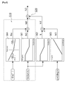
Fig. 3] Fig. 3 is a block diagram showing a control method of a power steering system in the embodiment of the present invention. - [
Fig. 4] Fig. 4 is a view showing a standby rotation speed map and a slope correction value map which are shown inFig. 3 . - [
Fig. 5] Fig. 5 is a hydraulic circuit diagram showing a conventional power steering system. - [
Fig. 6] Fig. 6 is a block diagram showing a control method of the conventional power steering system. - A power steering system in an embodiment of the present invention, a vehicle equipped with the power steering system, and a control method of the power steering system are described below by referring to the drawings. First, description is given of the vehicle equipped with the power steering system in the embodiment of the present invention by referring to
Fig. 1 . Here, illustration is such that an upper side ofFig. 1 is a front side of the vehicle and a lower side ofFig. 1 is a rear side of the vehicle. - Description is given by taking a so-called cab-over truck, including a
body 1a, acab 1b, and achassis 1c, as an example of thevehicle 1 of the embodiment. Since this cab-over truck has a short wheelbase and a high center of gravity, load transfer to front wheels is great, and the present invention is thus particularly effective when applied to the cab-over truck. However, the present invention can be also applied to a normal bonnet-type vehicle. - The
vehicle 1 transmits drive force generated in a power plant 2 to adrive shaft 3 and travels by usingrear wheels 9c and 9d (not illustrated) as drive wheels, the power plant 2 being formed of an engine (internal combustion engine) 2a, a clutch (drive force transmitting device) 2b, a transmission (gear shifting device) 2c, acrankshaft 2d, an alternator (power generator) 2e, and a cooling device (a radiator, a fan, and the like) 2f. - The
vehicle 1 also includes asteering device 4 formed of a steering wheel (also referred to as hand wheel) 4a and foot pedals (an accelerator pedal, a brake pedal, a clutch pedal, and the like) 4b, an ECU (control device) 5 called engine control unit, a steering angle sensor 6, avehicle speed sensor 7, and an acceleration sensor (G sensor) 8. - In addition, the
vehicle 1 includes an EHPS system (electro-hydraulic power steering system) 10 which operates in conjunction with thesteering wheel 4a and assists thesteering wheel 4a in steering offront wheels - Although the embodiment is described by giving an example of a front-wheel steering vehicle in which the
front wheels steering device 4 and the sensors 6 to 8 by using an electric circuit. However, a device for the control of the power plant 2 and a device for the control of thepower steering system 10 may be provided separately. - Here, how force act on the front wheels when the
vehicle 1 is travelling on a slope is described by referring toFig. 2 . In the description, W refers to the weight ofvehicle 1, G refers to the center of gravity of thevehicle 1, h refers to the height of the center of gravity (the height of the center of gravity G from the slope), θ refers to the slope angle, S refers to the wheelbase (distance between a front axle and a rear axle), a refers to the distance from the center of gravity to the front axle, b refers to the distance from the center of gravity to the rear axle, and bold lines in the drawing show action of force. - A front axle load Rf1 in slope descent of the
vehicle 1 can be expressed by the following math (1).
[Math 1]
- From the above math, it is found that the front axle load Rf1 in slope descent of the
vehicle 1 is greater than that in a case where thevehicle 1 is travelling on a flat surface (Rf1 = W·b/S). Particularly, in the cab-over truck, since the length of the wheelbase S is short relative to the entire length of thevehicle 1 and the height h of the center of gravity is high, the load transfer to thefront wheels body 1a further increases the height h of the center of gravity, the load transfer from thefront wheels vehicle 1 travels on a slope. - A front axle load Rf2 (not illustrated) in slope ascent of the
vehicle 1 can be expressed by the following math (2).
[Math 2]
- From the above math, it is found that the front axle load Rf2 in slope ascent of the
vehicle 1 is smaller than that in the case where thevehicle 1 is travelling on a flat surface. - As described above, since the front axle load Rf1 increases in slope descent of the
vehicle 1, steering force is increased from that in the case where thevehicle 1 is travelling on a flat surface. Moreover, since the front axle load Rf2 decreases in slope ascent of thevehicle 1, the steering force is reduced from that in the case where thevehicle 1 is travelling on a flat surface. - Next, a control method of the
power steering system 10 of the present invention is described with reference toFigs. 3 and4 . In the following description, a value calculated by the ECU 5 from a signal detected by the steering angle sensor 6 is referred to as steering speed ωn (deg/s), a value calculated by the ECU 5 from a signal detected by thevehicle speed sensor 7 is referred to as vehicle speed Vn (km/h), and a value calculated by the ECU 5 from a signal detected by theG sensor 8 is referred to as vehicle body angle θn (deg). - The control method of the
power steering system 10 in the embodiment of the present invention is a method in which a standby rotation speed N0 of the system control method shown inFig. 6 is increased and decreased according to the vehicle body angle θn before the standby rotation speed N0 and a steering correction value N1' are added to each other. - Moreover, this control method includes a first step S10 in which an
electric pump 11 supplies a standby fluid (hydraulic oil) to apower steering unit 13 when steering of thesteering wheel 4a is unnecessary (when thesteering wheel 4a is at a neutral position) and a second step S20 in which theelectric pump 11 supplies assisting fluid to thepower steering unit 13 when thesteering wheel 4a is steered and thepower steering unit 13 assists the steering of thesteering wheel 4a. - First, as shown in
Fig. 3 , the first step S10 is started. When thevehicle speed sensor 7 detects the vehicle speed Vn of the vehicle 1 (step S1), a standby rotation speed map M1 specifying the standby rotation speed N0 based on the vehicle speed Vn is referred and the standby rotation speed N0 corresponding to the vehicle speed Vn is thereby calculated (step S2). Then, the rotation speed of theelectric pump 11 is controlled to reach the calculated standby rotation speed N0 (step S3). - Next, when the
vehicle 1 travels on a slope, theG sensor 8 detects the vehicle body angle θn which is inclined in a slope (step S4). At this time, if theG sensor 8 is installed to detect only the acceleration in a vehicle body vertical direction of thevehicle 1, the detection value of theG sensor 8 decreases according to the slope angle θ. Hence, it is possible to perform calculation using inverse trigonometric function arc-cosine and easily detect the vehicle body angle θn. - Next, a slope correction value map M4 specifying a slope correction value Nx based on the vehicle body angle θn is referred and the slope correction value Nx corresponding to the detected vehicle body angle θn is thereby calculated (step S5) . Subsequently, the calculated slope correction value Nx is added to the standby rotation speed N0 and the on-slope standby rotation speed N0' is thereby calculated (step S6).
- As shown in the slope correction value map M4 of
Fig. 3 , the slope correction value Nx takes such a value that the standby rotation speed N0 is increased (positive value), when the vehicle body angle θn indicates slope descent, i.e. when thevehicle 1 is descending a slope and the front axle load Rf1 becomes greater than that in the case where the vehicle body angle θn is zero (horizontal). Moreover, the slope correction value Nx takes such a value that the standby rotation speed N0 is reduced (negative value), when the vehicle body angle θn indicates slope ascent, i.e. when thevehicle 1 is ascending a slope and the front axle load Rf2 becomes smaller than that in the case where the vehicle body angle θn is zero. - Moreover, the decrease/increase value of the slope correction value Nx should be determined based on the proportion in the wheelbase S. In a cab-over truck, since change in the front axle load in slope descent is great when the proportion in the wheelbase S is such that a<b is satisfied, the slope correction value Nx should be increased in the slope correction value map M4 when the vehicle body angle θn indicates slope descent of the
vehicle 1. Meanwhile, the slope correction value Nx should be decreased when the vehicle body angle θn indicates slope ascent of the vehicle. In this case, when the proportion in the wheelbase S is such that a<b is satisfied, the absolute value of the slope correction value Nx in slope descent is greater than the absolute value of the slope correction value Nx in slope ascent. - Here, a map showing that the on-slope standby rotation speed N0' increases and decreases according to the vehicle body angle θn is shown in
Fig. 4 . It is found from a map M5 obtained by adding the standby rotation speed map M1 and the slope correction value map M4 to each other that, as described above, the on-slope standby rotation speed N0' increases in slope descent of thevehicle 1 and decreases in slope ascent of thevehicle 1. Instead of performing steps S5 and S6, the on-slope standby rotation speed N0' may be calculated by using the on-slope standby rotation speed map M5 based on the vehicle speed Vn and the vehicle body angle θn. - After the on-slope standby rotation speed N0' is calculated, the rotation speed of the
electric pump 11 is controlled to reach the calculated on-slope standby rotation speed N0' (step S7) and the first step S10 is thus completed. - When the first step S10 is completed and the
steering wheel 4a is steered, the second step S20 described inFig. 6 is started. At this time, when thevehicle 1 is travelling on a slope, the steering correction value N1' is added to the on-slope standby rotation speed N0' calculated in the aforementioned first step S10 and a target rotation speed N2 is thereby calculated. Then, the rotation speed of theelectric pump 11 is controlled to reach the calculated target rotation speed N2 and the second step S20 is completed. - Meanwhile, when the
vehicle 1 is travelling on a horizontal surface, since the slope correction value Nx is zero, the steering correction value N1' is added to the standby rotation speed N0 and the target rotation speed N2 is thereby calculated. Then, the rotation speed of theelectric pump 11 is controlled to reach the calculated target rotation speed N2 and the second step S20 is completed. - According to the aforementioned control method, the supply amount of the standby fluid supplied from the
electric pump 11 to thepower steering unit 13 can be increased or decreased according to the vehicle body angle θn before the assist force of thepower steering unit 13 in the operation of thesteering wheel 4a is increased or decreased. Hence, it is possible to suppress jerky feeling due to insufficient steering force in slope descent and lack of response due to excessive steering force in slope ascent. - Moreover, the difference between the on-slope standby rotation speed N0' and the target rotation speed N2 is smaller than a difference in the case where the slope correction value Nx corresponding to the vehicle body angle θn is added upon the steering of the
steering wheel 4a. Hence, it is possible to improve responsiveness of thepower steering unit 13 in the slope descent and ascent of thevehicle 1. - This is due to the following reason. Since the change in the vehicle body angle θn corresponds to the change in the front axle load, the change in the front axle load is not affected or only slightly affected by a vehicle speed coefficient k and the steering speed ωn in the second step S20. Accordingly, in order to suppress the effect of the front axle load change on a steering operation, increasing and decreasing the standby rotation speed N0 corresponding to the vehicle speed Vn has a great effect.
- In addition, when the
vehicle 1 is travelling on not a slope but a substantially-horizontal road, theelectric pump 11 is driven at the standby rotation speed N0. Accordingly, it is possible to reduce pump loss and improve fuel. - In the aforementioned control method, the steering correction value N1' is calculated based on the signal detected by the steering angle sensor 6 and the target rotation speed N2 is thereby calculated. In addition to this, it is possible to add steps of suppressing a seizure phenomenon in the
power steering unit 13, kickback in straight travelling, and wobbling of thefront wheels electric pump 11 and the target rotation speed N2 does not increase, with factors other the operation of thesteering wheel 4a taken as disturbance. - Moreover, although the
G sensor 8 is used in the embodiment, an angle sensor capable of directly detecting the slope angle θ may be used instead of theG sensor 8. In this case, in step S5, a slope correction value map specifying the slope correction value Nx based on the slope angle θ is referred and the slope correction value Nx corresponding to the detected slope angle θ is thereby calculated. - Since the present invention can suppress both of jerky feeling in the steering operation due to insufficient steering force in slope descent of the vehicle and lack of response in the steering operation due to excessive steering force in slope ascent of the vehicle, the present invention can be used particularly in a vehicle such as a cab-over truck with a short wheelbase and a high center of gravity.
-
- 1
- vehicle
- 2
- power plant
- 3
- drive shaft
- 4
- steering device
- 5
- ECU (control device)
- 6
- steering angle sensor
- 7
- vehicle speed sensor
- 8
- G sensor (acceleration sensor)
- 10
- EHPS system (electro-hydraulic power steering system)
- 11
- electric pump
- 13
- power steering unit (steering assisting device)
- M1
- standby rotation speed map
- M2
- vehicle speed coefficient map
- M3
- steering speed sense map
- M4
- slope correction value map
- S10
- first step (first means)
- S20
- second step (second means) conventional power steering
Claims (5)
- A power steering system including: an electric pump configured to supply hydraulic oil to a steering assisting device configured to assist a steering performance of a steering wheel; and a control device configured to control a supply amount of the hydraulic oil by means of a rotation speed of the electric pump, characterized in that
the control device includes first control means to calculate an on-slope standby rotation speed and to control the electric pump such that the electric pump is set to the on-slope standby rotation speed, when a vehicle is descending or ascending a slope, the on-slope standby rotation speed calculated by correcting a standby rotation speed of the electric pump corresponding to a vehicle speed with a slope correction value calculated according to a slope angle or a vehicle body angle. - The power steering system according to claim 1, characterized in that the control device includes second control means to calculate a steering target rotation speed and to control the electric pump such that the electric pump is set to the steering target rotation speed, when the steering wheel is steered after control of the first control means, the steering target rotation speed calculated by correcting the on-slope standby rotation speed with a steering correction value corresponding to at least steering of the steering wheel.
- The power steering system according to claim 1 or 2, characterized in that
the control device includes a slope correction value map storing the slope correction value based on the slope angle or the vehicle body angle, and
the first control means includes means for:calculating the slope correction value from the slope correction value map, according to the slope angle or the vehicle body angle; andincreasing the standby rotation speed by the slope correcting value when the slope angle or the vehicle body angle indicates slope descent and decreasing the standby rotation speed by the slope correction value when the slope angle or the vehicle body angle indicates slope ascent. - A vehicle characterized in that the vehicle is equipped with the power steering system according to any one of claims 1 to 3.
- A control method of a power steering system including an electric pump configured to supply hydraulic oil to a steering assisting device configured to assist a steering performance of a steering wheel, characterized in that the control method of the power steering system comprises
controlling a supply amount of the hydraulic oil by driving the electric pump such that the electric pump is set to an on-slope standby rotation speed, when a vehicle is descending or ascending a slope, the on-slope standby rotation speed calculated by correcting a standby rotation speed calculated according to a vehicle speed with a slope correction value calculated according to a slope angle or a vehicle body angle.
Applications Claiming Priority (2)
| Application Number | Priority Date | Filing Date | Title |
|---|---|---|---|
| JP2012113645A JP5998630B2 (en) | 2012-05-17 | 2012-05-17 | Power steering system, vehicle equipped with the same, and control method thereof |
| PCT/JP2013/063503 WO2013172367A1 (en) | 2012-05-17 | 2013-05-15 | Power steering system, vehicle equipped with same, and control method thereof |
Publications (3)
| Publication Number | Publication Date |
|---|---|
| EP2851268A1 true EP2851268A1 (en) | 2015-03-25 |
| EP2851268A4 EP2851268A4 (en) | 2016-03-09 |
| EP2851268B1 EP2851268B1 (en) | 2017-03-15 |
Family
ID=49583771
Family Applications (1)
| Application Number | Title | Priority Date | Filing Date |
|---|---|---|---|
| EP13791657.3A Active EP2851268B1 (en) | 2012-05-17 | 2013-05-15 | Power steering system, vehicle equipped with same, and control method thereof |
Country Status (5)
| Country | Link |
|---|---|
| US (1) | US9333985B2 (en) |
| EP (1) | EP2851268B1 (en) |
| JP (1) | JP5998630B2 (en) |
| CN (1) | CN104302536B (en) |
| WO (1) | WO2013172367A1 (en) |
Families Citing this family (7)
| Publication number | Priority date | Publication date | Assignee | Title |
|---|---|---|---|---|
| WO2017073616A1 (en) | 2015-10-30 | 2017-05-04 | 株式会社小松製作所 | Work vehicle and work vehicle control method |
| JP6759822B2 (en) * | 2016-08-02 | 2020-09-23 | いすゞ自動車株式会社 | Steering assistance device and steering assist method |
| JP6686967B2 (en) * | 2017-05-29 | 2020-04-22 | トヨタ自動車株式会社 | Power steering device |
| CN111163995B (en) * | 2017-10-02 | 2023-05-09 | 蒂森克虏伯普利斯坦股份公司 | Steering system including steer-by-wire with feedback actuator having redundant sleep mode rotor position sensor |
| CN108177687B (en) * | 2017-12-27 | 2020-04-03 | 潍柴动力股份有限公司 | A vehicle steering system, new energy vehicle and steering method |
| DE102018127544A1 (en) * | 2018-11-05 | 2020-05-07 | Wacker Neuson Linz Gmbh | Work vehicle with speed-dependent steering |
| CN114852165B (en) * | 2022-06-02 | 2023-03-03 | 北京京深深向科技有限公司 | Control method and device of truck power-assisted steering system, electronic equipment and storage medium |
Family Cites Families (27)
| Publication number | Priority date | Publication date | Assignee | Title |
|---|---|---|---|---|
| JPS5414368B2 (en) * | 1973-03-15 | 1979-06-06 | ||
| JPS58152663A (en) * | 1982-03-05 | 1983-09-10 | Kayaba Ind Co Ltd | Flow rate controller for power steering |
| JPS5959574A (en) * | 1982-09-30 | 1984-04-05 | Jidosha Kiki Co Ltd | Power steering system control method |
| JPS6150877A (en) * | 1984-08-20 | 1986-03-13 | Toyota Motor Corp | Variable controller for power steering mechanism |
| JPS62258132A (en) * | 1986-05-02 | 1987-11-10 | Hitachi Constr Mach Co Ltd | Hydraulically driven travelling device |
| JPH0227193A (en) | 1988-07-13 | 1990-01-29 | Mitsui Constr Co Ltd | Starting device for submersible pump with float |
| JP2528955B2 (en) * | 1988-12-29 | 1996-08-28 | 日産自動車株式会社 | Vehicle power drift control device |
| JPH05221330A (en) * | 1992-02-17 | 1993-08-31 | Mazda Motor Corp | Steering control device for vehicle |
| US6009364A (en) * | 1992-10-09 | 1999-12-28 | Mitsubishi Denki Kabushiki Kaisha | Power steering control apparatus for motor vehicle |
| US6092618A (en) * | 1997-10-31 | 2000-07-25 | General Motors Corporation | Electro-hydraulic power steering control with fluid temperature and motor speed compensation of power steering load signal |
| JP3688140B2 (en) * | 1998-11-10 | 2005-08-24 | 光洋精工株式会社 | Power steering device |
| US6425454B1 (en) * | 2000-02-16 | 2002-07-30 | Ford Global Technologies, Inc. | Vehicle electric power assist steering system and method using velocity based torque estimation |
| JP3712387B2 (en) * | 2002-01-25 | 2005-11-02 | カヤバ工業株式会社 | Power steering device |
| JP4066933B2 (en) * | 2003-11-10 | 2008-03-26 | 株式会社ジェイテクト | Flow control device for power steering device |
| JP4363257B2 (en) * | 2004-06-01 | 2009-11-11 | 株式会社ジェイテクト | Power steering device |
| DE102005041071B4 (en) * | 2005-08-30 | 2009-05-28 | Lucas Automotive Gmbh | System for controlling the downhill of a motor vehicle |
| JP4595932B2 (en) * | 2006-12-08 | 2010-12-08 | トヨタ自動車株式会社 | Vehicle control device |
| US7832523B2 (en) * | 2007-03-29 | 2010-11-16 | Ford Global Technologies | Power assist steering system |
| JP2009113733A (en) * | 2007-11-09 | 2009-05-28 | Hitachi Ltd | Power steering device |
| JP4609515B2 (en) * | 2008-04-02 | 2011-01-12 | トヨタ自動車株式会社 | Vehicle steering control device |
| JP4999984B2 (en) * | 2008-04-04 | 2012-08-15 | 三菱電機株式会社 | Electric power steering control device |
| JP5407171B2 (en) * | 2008-04-15 | 2014-02-05 | 株式会社ジェイテクト | Electric power steering device |
| EP2282402B1 (en) * | 2008-05-21 | 2020-09-02 | JTEKT Corporation | Electric pump device |
| SE533784C2 (en) * | 2009-05-20 | 2011-01-11 | Scania Cv Ab | Power steering system |
| JP5403368B2 (en) * | 2010-02-26 | 2014-01-29 | アイシン・エィ・ダブリュ株式会社 | Vehicle drive device |
| JP5909861B2 (en) * | 2011-04-04 | 2016-04-27 | 株式会社ジェイテクト | Hydraulic device and hydraulic power steering device including the same |
| US8560178B2 (en) * | 2011-11-30 | 2013-10-15 | Steering Solutions Ip Holding Corporation | System and method for providing steering torque assistance to an electrically-powered steering apparatus of a vehicle |
-
2012
- 2012-05-17 JP JP2012113645A patent/JP5998630B2/en not_active Expired - Fee Related
-
2013
- 2013-05-15 EP EP13791657.3A patent/EP2851268B1/en active Active
- 2013-05-15 CN CN201380025868.0A patent/CN104302536B/en active Active
- 2013-05-15 US US14/401,159 patent/US9333985B2/en active Active
- 2013-05-15 WO PCT/JP2013/063503 patent/WO2013172367A1/en not_active Ceased
Also Published As
| Publication number | Publication date |
|---|---|
| JP5998630B2 (en) | 2016-09-28 |
| US20150105980A1 (en) | 2015-04-16 |
| EP2851268A4 (en) | 2016-03-09 |
| JP2013241025A (en) | 2013-12-05 |
| WO2013172367A1 (en) | 2013-11-21 |
| CN104302536B (en) | 2017-03-01 |
| CN104302536A (en) | 2015-01-21 |
| EP2851268B1 (en) | 2017-03-15 |
| US9333985B2 (en) | 2016-05-10 |
Similar Documents
| Publication | Publication Date | Title |
|---|---|---|
| EP2851268B1 (en) | Power steering system, vehicle equipped with same, and control method thereof | |
| US9669813B2 (en) | Vehicle driving support control device | |
| US8244435B2 (en) | Method and system for determining an optimal steering angle in understeer situations in a vehicle | |
| US8989964B2 (en) | Vehicle speed control device | |
| US9522697B2 (en) | Control method for electrohydraulic power steering system | |
| US8700280B2 (en) | Road surface frictional coefficient estimation device, driving force distribution control device and four-wheel-drive vehicle | |
| CN108725575B (en) | Apparatus and method for controlling motor-driven power steering system | |
| US20180086374A1 (en) | Control unit for vehicle and control method for vehicle | |
| US20130103263A1 (en) | Vehicle stability control method and system | |
| US11541876B2 (en) | Electronic stability control method for vehicle | |
| US20040199316A1 (en) | Vehicle motion control method and vehicle motion control apparatus | |
| EP2495155B1 (en) | System and method for preventing steering pull in vehicle | |
| EP3747669B1 (en) | Vehicle attitude control system | |
| EP3656648B1 (en) | Apparatus and method for controlling steering system of vehicle | |
| EP3747715A1 (en) | Vehicle attitude control system | |
| JP2005297622A (en) | Steering system | |
| JP4636255B2 (en) | Wheel lateral force estimation device and steering reaction force control device | |
| JP4443582B2 (en) | Understeer suppression device | |
| JP5478470B2 (en) | Electric power steering device | |
| US20210309289A1 (en) | Vehicle Control System, Vehicle Control Method, and Electric Power Steering System | |
| CN102407847B (en) | Form the method representing and cross in driving and turn over the Severity Index of the journey order of severity | |
| JP2013082319A (en) | Travel controller for vehicle | |
| JP6020097B2 (en) | Vehicle travel control device | |
| JP2006035930A (en) | Vehicle attitude control device | |
| JP4525257B2 (en) | Vehicle steering control device |
Legal Events
| Date | Code | Title | Description |
|---|---|---|---|
| PUAI | Public reference made under article 153(3) epc to a published international application that has entered the european phase |
Free format text: ORIGINAL CODE: 0009012 |
|
| 17P | Request for examination filed |
Effective date: 20141208 |
|
| AK | Designated contracting states |
Kind code of ref document: A1 Designated state(s): AL AT BE BG CH CY CZ DE DK EE ES FI FR GB GR HR HU IE IS IT LI LT LU LV MC MK MT NL NO PL PT RO RS SE SI SK SM TR |
|
| AX | Request for extension of the european patent |
Extension state: BA ME |
|
| DAX | Request for extension of the european patent (deleted) | ||
| RA4 | Supplementary search report drawn up and despatched (corrected) |
Effective date: 20160210 |
|
| RIC1 | Information provided on ipc code assigned before grant |
Ipc: B62D 5/07 20060101ALI20160204BHEP Ipc: B62D 101/00 20060101ALI20160204BHEP Ipc: B62D 5/065 20060101ALI20160204BHEP Ipc: B62D 6/00 20060101AFI20160204BHEP Ipc: B62D 5/06 20060101ALI20160204BHEP Ipc: B62D 15/02 20060101ALI20160204BHEP Ipc: B62D 137/00 20060101ALI20160204BHEP Ipc: B62D 119/00 20060101ALI20160204BHEP |
|
| GRAP | Despatch of communication of intention to grant a patent |
Free format text: ORIGINAL CODE: EPIDOSNIGR1 |
|
| RIC1 | Information provided on ipc code assigned before grant |
Ipc: B62D 137/00 20060101ALI20160928BHEP Ipc: B62D 101/00 20060101ALI20160928BHEP Ipc: B62D 119/00 20060101ALI20160928BHEP Ipc: B62D 5/065 20060101ALI20160928BHEP Ipc: B62D 5/06 20060101ALI20160928BHEP Ipc: B62D 6/00 20060101AFI20160928BHEP Ipc: B62D 5/07 20060101ALI20160928BHEP Ipc: B62D 15/02 20060101ALI20160928BHEP |
|
| INTG | Intention to grant announced |
Effective date: 20161020 |
|
| GRAS | Grant fee paid |
Free format text: ORIGINAL CODE: EPIDOSNIGR3 |
|
| GRAA | (expected) grant |
Free format text: ORIGINAL CODE: 0009210 |
|
| AK | Designated contracting states |
Kind code of ref document: B1 Designated state(s): AL AT BE BG CH CY CZ DE DK EE ES FI FR GB GR HR HU IE IS IT LI LT LU LV MC MK MT NL NO PL PT RO RS SE SI SK SM TR |
|
| REG | Reference to a national code |
Ref country code: CH Ref legal event code: EP Ref country code: GB Ref legal event code: FG4D |
|
| REG | Reference to a national code |
Ref country code: IE Ref legal event code: FG4D |
|
| REG | Reference to a national code |
Ref country code: AT Ref legal event code: REF Ref document number: 875216 Country of ref document: AT Kind code of ref document: T Effective date: 20170415 |
|
| REG | Reference to a national code |
Ref country code: DE Ref legal event code: R096 Ref document number: 602013018649 Country of ref document: DE |
|
| REG | Reference to a national code |
Ref country code: FR Ref legal event code: PLFP Year of fee payment: 5 |
|
| REG | Reference to a national code |
Ref country code: NL Ref legal event code: MP Effective date: 20170315 |
|
| REG | Reference to a national code |
Ref country code: LT Ref legal event code: MG4D |
|
| PG25 | Lapsed in a contracting state [announced via postgrant information from national office to epo] |
Ref country code: LT Free format text: LAPSE BECAUSE OF FAILURE TO SUBMIT A TRANSLATION OF THE DESCRIPTION OR TO PAY THE FEE WITHIN THE PRESCRIBED TIME-LIMIT Effective date: 20170315 Ref country code: HR Free format text: LAPSE BECAUSE OF FAILURE TO SUBMIT A TRANSLATION OF THE DESCRIPTION OR TO PAY THE FEE WITHIN THE PRESCRIBED TIME-LIMIT Effective date: 20170315 Ref country code: NO Free format text: LAPSE BECAUSE OF FAILURE TO SUBMIT A TRANSLATION OF THE DESCRIPTION OR TO PAY THE FEE WITHIN THE PRESCRIBED TIME-LIMIT Effective date: 20170615 Ref country code: FI Free format text: LAPSE BECAUSE OF FAILURE TO SUBMIT A TRANSLATION OF THE DESCRIPTION OR TO PAY THE FEE WITHIN THE PRESCRIBED TIME-LIMIT Effective date: 20170315 Ref country code: GR Free format text: LAPSE BECAUSE OF FAILURE TO SUBMIT A TRANSLATION OF THE DESCRIPTION OR TO PAY THE FEE WITHIN THE PRESCRIBED TIME-LIMIT Effective date: 20170616 |
|
| REG | Reference to a national code |
Ref country code: AT Ref legal event code: MK05 Ref document number: 875216 Country of ref document: AT Kind code of ref document: T Effective date: 20170315 |
|
| PG25 | Lapsed in a contracting state [announced via postgrant information from national office to epo] |
Ref country code: RS Free format text: LAPSE BECAUSE OF FAILURE TO SUBMIT A TRANSLATION OF THE DESCRIPTION OR TO PAY THE FEE WITHIN THE PRESCRIBED TIME-LIMIT Effective date: 20170315 Ref country code: BG Free format text: LAPSE BECAUSE OF FAILURE TO SUBMIT A TRANSLATION OF THE DESCRIPTION OR TO PAY THE FEE WITHIN THE PRESCRIBED TIME-LIMIT Effective date: 20170615 Ref country code: LU Free format text: LAPSE BECAUSE OF NON-PAYMENT OF DUE FEES Effective date: 20170531 Ref country code: SE Free format text: LAPSE BECAUSE OF FAILURE TO SUBMIT A TRANSLATION OF THE DESCRIPTION OR TO PAY THE FEE WITHIN THE PRESCRIBED TIME-LIMIT Effective date: 20170315 Ref country code: LV Free format text: LAPSE BECAUSE OF FAILURE TO SUBMIT A TRANSLATION OF THE DESCRIPTION OR TO PAY THE FEE WITHIN THE PRESCRIBED TIME-LIMIT Effective date: 20170315 |
|
| PG25 | Lapsed in a contracting state [announced via postgrant information from national office to epo] |
Ref country code: NL Free format text: LAPSE BECAUSE OF FAILURE TO SUBMIT A TRANSLATION OF THE DESCRIPTION OR TO PAY THE FEE WITHIN THE PRESCRIBED TIME-LIMIT Effective date: 20170315 |
|
| PG25 | Lapsed in a contracting state [announced via postgrant information from national office to epo] |
Ref country code: SK Free format text: LAPSE BECAUSE OF FAILURE TO SUBMIT A TRANSLATION OF THE DESCRIPTION OR TO PAY THE FEE WITHIN THE PRESCRIBED TIME-LIMIT Effective date: 20170315 Ref country code: RO Free format text: LAPSE BECAUSE OF FAILURE TO SUBMIT A TRANSLATION OF THE DESCRIPTION OR TO PAY THE FEE WITHIN THE PRESCRIBED TIME-LIMIT Effective date: 20170315 Ref country code: AT Free format text: LAPSE BECAUSE OF FAILURE TO SUBMIT A TRANSLATION OF THE DESCRIPTION OR TO PAY THE FEE WITHIN THE PRESCRIBED TIME-LIMIT Effective date: 20170315 Ref country code: ES Free format text: LAPSE BECAUSE OF FAILURE TO SUBMIT A TRANSLATION OF THE DESCRIPTION OR TO PAY THE FEE WITHIN THE PRESCRIBED TIME-LIMIT Effective date: 20170315 Ref country code: IT Free format text: LAPSE BECAUSE OF FAILURE TO SUBMIT A TRANSLATION OF THE DESCRIPTION OR TO PAY THE FEE WITHIN THE PRESCRIBED TIME-LIMIT Effective date: 20170315 Ref country code: CZ Free format text: LAPSE BECAUSE OF FAILURE TO SUBMIT A TRANSLATION OF THE DESCRIPTION OR TO PAY THE FEE WITHIN THE PRESCRIBED TIME-LIMIT Effective date: 20170315 Ref country code: EE Free format text: LAPSE BECAUSE OF FAILURE TO SUBMIT A TRANSLATION OF THE DESCRIPTION OR TO PAY THE FEE WITHIN THE PRESCRIBED TIME-LIMIT Effective date: 20170315 |
|
| PG25 | Lapsed in a contracting state [announced via postgrant information from national office to epo] |
Ref country code: IS Free format text: LAPSE BECAUSE OF FAILURE TO SUBMIT A TRANSLATION OF THE DESCRIPTION OR TO PAY THE FEE WITHIN THE PRESCRIBED TIME-LIMIT Effective date: 20170715 Ref country code: PT Free format text: LAPSE BECAUSE OF FAILURE TO SUBMIT A TRANSLATION OF THE DESCRIPTION OR TO PAY THE FEE WITHIN THE PRESCRIBED TIME-LIMIT Effective date: 20170717 Ref country code: PL Free format text: LAPSE BECAUSE OF FAILURE TO SUBMIT A TRANSLATION OF THE DESCRIPTION OR TO PAY THE FEE WITHIN THE PRESCRIBED TIME-LIMIT Effective date: 20170315 Ref country code: SM Free format text: LAPSE BECAUSE OF FAILURE TO SUBMIT A TRANSLATION OF THE DESCRIPTION OR TO PAY THE FEE WITHIN THE PRESCRIBED TIME-LIMIT Effective date: 20170315 |
|
| REG | Reference to a national code |
Ref country code: DE Ref legal event code: R097 Ref document number: 602013018649 Country of ref document: DE |
|
| REG | Reference to a national code |
Ref country code: CH Ref legal event code: PL |
|
| PLBE | No opposition filed within time limit |
Free format text: ORIGINAL CODE: 0009261 |
|
| STAA | Information on the status of an ep patent application or granted ep patent |
Free format text: STATUS: NO OPPOSITION FILED WITHIN TIME LIMIT |
|
| PG25 | Lapsed in a contracting state [announced via postgrant information from national office to epo] |
Ref country code: MC Free format text: LAPSE BECAUSE OF FAILURE TO SUBMIT A TRANSLATION OF THE DESCRIPTION OR TO PAY THE FEE WITHIN THE PRESCRIBED TIME-LIMIT Effective date: 20170315 Ref country code: DK Free format text: LAPSE BECAUSE OF FAILURE TO SUBMIT A TRANSLATION OF THE DESCRIPTION OR TO PAY THE FEE WITHIN THE PRESCRIBED TIME-LIMIT Effective date: 20170315 |
|
| 26N | No opposition filed |
Effective date: 20171218 |
|
| REG | Reference to a national code |
Ref country code: IE Ref legal event code: MM4A |
|
| PG25 | Lapsed in a contracting state [announced via postgrant information from national office to epo] |
Ref country code: CH Free format text: LAPSE BECAUSE OF NON-PAYMENT OF DUE FEES Effective date: 20170531 Ref country code: SI Free format text: LAPSE BECAUSE OF FAILURE TO SUBMIT A TRANSLATION OF THE DESCRIPTION OR TO PAY THE FEE WITHIN THE PRESCRIBED TIME-LIMIT Effective date: 20170315 Ref country code: LI Free format text: LAPSE BECAUSE OF NON-PAYMENT OF DUE FEES Effective date: 20170531 |
|
| PG25 | Lapsed in a contracting state [announced via postgrant information from national office to epo] |
Ref country code: LU Free format text: LAPSE BECAUSE OF NON-PAYMENT OF DUE FEES Effective date: 20170515 |
|
| REG | Reference to a national code |
Ref country code: BE Ref legal event code: MM Effective date: 20170531 |
|
| PG25 | Lapsed in a contracting state [announced via postgrant information from national office to epo] |
Ref country code: IE Free format text: LAPSE BECAUSE OF NON-PAYMENT OF DUE FEES Effective date: 20170515 |
|
| REG | Reference to a national code |
Ref country code: FR Ref legal event code: PLFP Year of fee payment: 6 |
|
| PG25 | Lapsed in a contracting state [announced via postgrant information from national office to epo] |
Ref country code: BE Free format text: LAPSE BECAUSE OF NON-PAYMENT OF DUE FEES Effective date: 20170531 |
|
| PG25 | Lapsed in a contracting state [announced via postgrant information from national office to epo] |
Ref country code: MT Free format text: LAPSE BECAUSE OF NON-PAYMENT OF DUE FEES Effective date: 20170515 |
|
| PG25 | Lapsed in a contracting state [announced via postgrant information from national office to epo] |
Ref country code: HU Free format text: LAPSE BECAUSE OF FAILURE TO SUBMIT A TRANSLATION OF THE DESCRIPTION OR TO PAY THE FEE WITHIN THE PRESCRIBED TIME-LIMIT; INVALID AB INITIO Effective date: 20130515 |
|
| PG25 | Lapsed in a contracting state [announced via postgrant information from national office to epo] |
Ref country code: CY Free format text: LAPSE BECAUSE OF FAILURE TO SUBMIT A TRANSLATION OF THE DESCRIPTION OR TO PAY THE FEE WITHIN THE PRESCRIBED TIME-LIMIT Effective date: 20170315 |
|
| PG25 | Lapsed in a contracting state [announced via postgrant information from national office to epo] |
Ref country code: MK Free format text: LAPSE BECAUSE OF FAILURE TO SUBMIT A TRANSLATION OF THE DESCRIPTION OR TO PAY THE FEE WITHIN THE PRESCRIBED TIME-LIMIT Effective date: 20170315 |
|
| PG25 | Lapsed in a contracting state [announced via postgrant information from national office to epo] |
Ref country code: TR Free format text: LAPSE BECAUSE OF FAILURE TO SUBMIT A TRANSLATION OF THE DESCRIPTION OR TO PAY THE FEE WITHIN THE PRESCRIBED TIME-LIMIT Effective date: 20170315 |
|
| PG25 | Lapsed in a contracting state [announced via postgrant information from national office to epo] |
Ref country code: AL Free format text: LAPSE BECAUSE OF FAILURE TO SUBMIT A TRANSLATION OF THE DESCRIPTION OR TO PAY THE FEE WITHIN THE PRESCRIBED TIME-LIMIT Effective date: 20170315 |
|
| PGFP | Annual fee paid to national office [announced via postgrant information from national office to epo] |
Ref country code: GB Payment date: 20220401 Year of fee payment: 10 Ref country code: FR Payment date: 20220408 Year of fee payment: 10 |
|
| GBPC | Gb: european patent ceased through non-payment of renewal fee |
Effective date: 20230515 |
|
| PG25 | Lapsed in a contracting state [announced via postgrant information from national office to epo] |
Ref country code: GB Free format text: LAPSE BECAUSE OF NON-PAYMENT OF DUE FEES Effective date: 20230515 |
|
| PG25 | Lapsed in a contracting state [announced via postgrant information from national office to epo] |
Ref country code: FR Free format text: LAPSE BECAUSE OF NON-PAYMENT OF DUE FEES Effective date: 20230531 |
|
| PGFP | Annual fee paid to national office [announced via postgrant information from national office to epo] |
Ref country code: DE Payment date: 20250423 Year of fee payment: 13 |