EP2851018A1 - Medical apparatus system and liquid supply device - Google Patents
Medical apparatus system and liquid supply device Download PDFInfo
- Publication number
- EP2851018A1 EP2851018A1 EP14185317.6A EP14185317A EP2851018A1 EP 2851018 A1 EP2851018 A1 EP 2851018A1 EP 14185317 A EP14185317 A EP 14185317A EP 2851018 A1 EP2851018 A1 EP 2851018A1
- Authority
- EP
- European Patent Office
- Prior art keywords
- liquid
- unit
- supply
- pressure
- medical apparatus
- Prior art date
- Legal status (The legal status is an assumption and is not a legal conclusion. Google has not performed a legal analysis and makes no representation as to the accuracy of the status listed.)
- Granted
Links
Images





Classifications
-
- A—HUMAN NECESSITIES
- A61—MEDICAL OR VETERINARY SCIENCE; HYGIENE
- A61B—DIAGNOSIS; SURGERY; IDENTIFICATION
- A61B17/00—Surgical instruments, devices or methods
- A61B17/32—Surgical cutting instruments
- A61B17/3203—Fluid jet cutting instruments
-
- A—HUMAN NECESSITIES
- A61—MEDICAL OR VETERINARY SCIENCE; HYGIENE
- A61B—DIAGNOSIS; SURGERY; IDENTIFICATION
- A61B17/00—Surgical instruments, devices or methods
- A61B2017/00017—Electrical control of surgical instruments
- A61B2017/00137—Details of operation mode
- A61B2017/00154—Details of operation mode pulsed
Definitions
- the present invention relates to a technique for supplying a liquid to a medical apparatus.
- JP-A-2001-292963 is known as a technique for improving responsiveness of liquid ejection and stop in a medical apparatus which ejects a liquid.
- JP-A-2001-292963 discloses a technique in which cleaning water is pressure-fed by a pump to a cleaning water feeding channel of an endoscope via a water feeding tube and in which the pump is operated reversely for a predetermined time immediately after the operation of the pump is stopped, thus lowering the pressure of the pressure-fed cleaning water in the water feeding tube.
- JP-A-2001-292963 improves responsiveness of the stop of water feeding but cannot improve responsiveness of the start of water feeding.
- An advantage of some aspects of the invention is to solve at least a part of the problems described above, and the invention can be implemented as the following forms.
- An aspect of the invention provides a medical apparatus system.
- the medical apparatus system includes: a medical apparatus having an ejection unit which ejects a liquid; and a liquid supply device which supplies the liquid to the medical apparatus.
- the liquid supply device includes: a supply channel through which the liquid is supplied to the ej ection unit; a pressurizing unit which pressurizes the liquid in the supply channel; a blocking unit which blocks the supply channel; and a control unit which causes the pressurizing unit to pressurize the liquid in the supply channel in the state where the supply channel is blocked by the blocking unit.
- the liquid in the supply channel is pressurized in the state where the supply channel is blocked by the blocking unit. Therefore, when the blocking unit releases the channel, the liquid that is pressurized in advance can be supplied stably to the medical apparatus.
- control unit may cause the blocking unit to block the supply channel when the ejection unit stops the ejection. According to the medical apparatus system of this configuration, responsiveness of the stop of ejection can be improved when the ejection unit of the medical apparatus stops the ejection.
- the medical apparatus system may further include a pressure setting unit which sets a first pressure that is a pressure with which the pressurizing unit pressurizes the liquid when the ejection unit ejects the liquid, and the control unit may set a second pressure that is a pressure with which the pressurizing unit pressurizes the liquid in the supply channel in the state where the supply channel is blocked by the blocking unit, on the basis of the first pressure that is set.
- the liquid pressurized with a proper pressure corresponding to the first pressure that is set can be supplied to the medical apparatus.
- the ejection unit may include an actuator which provides a pulsed flow for the ejected liquid, and an applied voltage setting unit which sets an applied voltage for driving the actuator, and the control unit may set a second pressure that is a pressure with which the pressurizing unit pressurizes the liquid in the supply channel in the state where the supply channel is blocked by the blocking unit, on the basis of the applied voltage that is set.
- the liquid pressurized with a proper pressure corresponding to the applied voltage for driving the actuator can be supplied to the medical apparatus.
- the liquid supply device which supplies a liquid to a medical apparatus.
- the liquid supply device includes: a supply channel through which the liquid is supplied to the medical apparatus; a pressurizing unit which pressurizes the liquid in the supply channel; a blocking unit which blocks the supply channel; and a control unit which causes the pressurizing unit to pressurize the liquid in the supply channel in the state where the supply channel is blocked by the blocking unit.
- the liquid in the supply channel is pressurized in the state where the supply channel is blocked by the blocking unit. Therefore, when the blocking unit releases the channel, the liquid that is pressurized in advance can be supplied stably to the medical apparatus.
- a system including one or more of two components of a medical apparatus and a liquid supply device can be realized.
- the liquid supply device can be realized as a device including one or more of four components of a supply channel, a pressurizing unit, a blocking unit, and a control unit. That is, the system may or may not include the medical apparatus.
- the system may or may not include the liquid supply device.
- the liquid supply device may or may not include the supply channel.
- the liquid supply device may or may not include the pressurizing unit.
- the liquid supply device may or may not include the blocking unit.
- the liquid supply device may or may not include the control unit.
- the medical apparatus may be configured as a medical apparatus having an ejection unit which ejects a liquid.
- the liquid supply device may be configured as a liquid supply device which supplies the liquid to the medical apparatus.
- the supply channel may be configured as a supply channel through which the liquid is supplied to the ejection unit.
- the pressurizing unit may be configured as a pressurizing unit which pressurizes the liquid in the supply channel.
- the blocking unit may be configured as a blocking unit which blocks the supply channel.
- the control unit may be configured as a control unit which causes the pressurizing unit to pressurize the liquid in the supply channel in the state where the supply channel is blocked by the blocking unit.
- the invention can also be implemented in various other forms other than a system.
- the invention can be implemented in the form of a liquid supply method, a liquid ejection device, a liquid ejection method, a medical apparatus or the like.
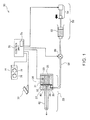
- FIG. 1 is an explanatory view illustrating the configuration of a medical apparatus system 10 as a first embodiment of the invention.
- the medical apparatus system 10 is used as a surgical knife which ejects a liquid to an affected part and thus incises or excises the affected part.
- the medical apparatus system 10 includes a liquid ejection device 20 as a medical apparatus, a liquid supply unit 50, and a control unit 70.
- the liquid ejection device 20 and the liquid supply unit 50 are connected to each other via a liquid supply channel 56.
- the liquid supply channel 56 is made of polyvinyl chloride.
- the liquid supply channel 56 may also be made of various resins such as silicone or thermoplastic elastomer.
- a blocking unit 60 is installed on the liquid supply channel 56.
- a foot switch 72 and an ejection condition setting unit 74 are connected to the control unit 70.
- the control unit 70 also stores table data Tb.
- the liquid supply unit 50 supplies a liquid to the liquid ejection device 20.
- the liquid supply unit 50 has a syringe 52 and a pressurizing unit 54.
- the syringe 52 accommodates a physiological saline solution as the liquid.
- various other liquids such as sterilized water for medical use and pure water can also be employed.
- the pressurizing unit 54 is an actuator which presses the syringe 52 and thus pressurizes the liquid inside the syringe 52.
- the pressurizing unit 54 has a linear motor. As the linear motor is horizontally driven, the syringe 52 is pressed and the liquid inside the syringe 52 is pressurized. The liquid inside the syringe 52 pressurized by the pressurizing unit 54 is supplied to the liquid ejection device 20 via the liquid supply channel 56.
- the liquid ejection device 20 provides pulsation for the liquid supplied from the liquid supply unit 50 and ejects the pulsed liquid.
- the user of the medical apparatus system 10 applies the pulsed liquid ejected from the liquid ejection device 20 to an affected part of a patient and thus incises or excises the affected part.
- the liquid ejection device 20 includes a first case 31, a second case 32, a third case 33, a piezoelectric element 35, a reinforcement board 36, a diaphragm 37, and an ejection tube 42.
- the first case 31 is a cylindrical member. One end of the first case 31 is joined to the second case 32. The other end of the first case 31 is sealed by the third case 33.
- the piezoelectric element 35 is arranged in the space formed inside the first case 31.
- the piezoelectric element 35 is a multilayer piezoelectric element. One end of the piezoelectric element 35 is fixed to the diaphragm 37 via the reinforcement board 36. The other end of the piezoelectric element 35 is fixed to the third case 33.
- the diaphragm 37 is made of a metallic thin film and the peripheral edge thereof is fixed to the first case 31.
- a housing chamber 38 is formed between the diaphragm 37 and the second case 32. The housing chamber 38 is changed in volume by the driving of the piezoelectric element 35.
- a first channel 39 which causes the liquid to flow into the housing chamber 38 is formed in the second case 32.
- the first channel 39 is connected to the liquid supply channel 56.
- a second channel 40 which causes the liquid housed in the housing chamber 38 to flow out is formed in the second case 32.
- the second channel 40 is connected to the ejection tube 42. The operation of the liquid ejection device 20 thus configured is controlled by the control unit 70.
- the control unit 70 controls the operation of the entire medical apparatus system 10.
- the foot switch 72 which the user operates with a foot, is connected to the control unit 70.
- the control unit 70 controls the liquid supply unit 50 to supply the liquid to the liquid ejection device 20 (housing chamber 38) and also transmits a drive signal to the piezoelectric element 35.
- the liquid supplied from the liquid supply unit 50 flows into the housing chamber 38 via the liquid supply channel 56 and the first channel 39.
- the piezoelectric element 35 receives the drive signal from the control unit 70, the piezoelectric element 35 oscillates at a predetermined frequency.
- the volume of the housing chamber 38 changes via the diaphragm 37 and the liquid housed in the housing chamber 38 is pressurized. Pulsation is provided for the liquid pressurized or depressurized at the predetermined frequency.
- the liquid is ejected outside as a pulsed liquid through the second channel 40 and the ejection tube 42.
- the pulsed liquid refers to a liquid in the state where the flow rate or flow speed varies.
- the way to eject the liquid in a pulsed form may include intermittent ejection in which ejection and stop are repeated. However, since it suffices that the flow rate or flow speed of the liquid varies, the ejection of the pulsed liquid need not necessarily be intermittent ejection.
- the ejection condition setting unit 74 for the user to set an ejection condition of the liquid is connected to the control unit 70.
- the ejection condition setting unit 74 includes a flow rate setting unit 76 and an applied voltage setting unit 78.
- the flow rate setting unit 76 is a dial-type operation unit for the user to set a flow rate Q (ml/min) of the liquid supplied from the liquid supply unit 50 to the liquid ejection device 20.
- the applied voltage setting unit 78 is a dial-type operation unit for the user to set an applied voltage E (V) of the drive signal transmitted to the piezoelectric element 35.
- the user can adjust the combination of the value of the flow rate Q and the value of the applied voltage E and thus set various ejection conditions of the liquid ejected from the liquid ejection device 20, such as the ejection pressure, flow rate, and droplet shape of the liquid ejected from the liquid ejection device 20.
- the ejection condition setting unit 74 may also include other operation units than the flow rate setting unit 76 and the applied voltage setting unit 78.
- the ejection condition setting unit 74 may include operation units for setting various other ejection conditions, for example, a frequency setting unit for the user to set a frequency of the applied voltage E, and a waveform setting unit for the user to set a waveform of the drive signal, or the like.
- the control unit 70 stores the table data Tb.
- the table data Tb is a two-dimensional lookup table which outputs a pressure (supply pressure SP) with which the liquid supply unit 50 supplies the liquid, with respect to the two parameters of the flow rate Q and the applied voltage E.
- the table data Tb will be described in detail later.
- the blocking unit 60 is provided on the liquid supply channel 56.
- the blocking unit 60 blocks and opens the liquid supply channel 56.
- FIG. 2 is an explanatory view illustrating the blocking unit 60.
- the blocking unit 60 has pressing parts 62.
- the pressing parts 62 of the blocking unit 60 sandwich and press the liquid supply channel 56 from outside, thus blocking the liquid supply channel 56.
- the blocking unit 60 is a solenoid valve.
- various other valves capable of blocking the liquid supply unit 50 can be employed, such as a globe valve, ball valve, butterfly valve, or diaphragm valve.
- the operation of the blocking unit 60 is controlled by the control unit 70.
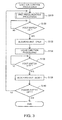
- FIG. 3 is a flowchart showing the flow of the ejection control processing.
- the ejection control processing is started as the user turns on the power supply (not shown) of the medical apparatus system 10.
- the control unit 70 carries out pre-pressurization processing (Step S110), after the liquid supply unit 50 supplies the liquid to the liquid supply channel 56 and the liquid is supplied to the point in the liquid supply channel 56 to be blocked by the blocking unit 60.
- the pre-pressurization processing is processing to adjust the internal pressure of the liquid supply channel 56 in advance, in the state where the liquid supply channel 56 is blocked by the blocking unit 60 before the user turns on the foot switch 72. The pre-pressurization processing will be described in detail later.
- Step S130 the control unit 70 controls the blocking unit 60 to open the liquid supply channel 56 (Step S132). Then, the control unit 70 carries out liquid ejection processing in which the liquid is ej ected from the liquid ejection device 20 (Step S134). Specifically, the control unit 70 controls the liquid supply unit 50 to supply the liquid to the liquid ejection device 20 (housing chamber 38) and also transmits a drive signal to the piezoelectric element 35. As the liquid ejection processing is executed, the pulsed liquid is ejected from the liquid ejection device 20.
- the supply pressure SP which is the pressure with which the liquid supply unit 50 supplies the liquid to the liquid ejection device 20, is determined by the control unit 70, using the flow rate Q, the applied voltage E, and the table data Tb, described below.
- the liquid supply unit 50 drives the pressurizing unit 54 under the control of the control unit 70 and supplies the liquid to the liquid ejection device 20 with the supply pressure SP.
- Step S136 As the user turns off the foot switch 72 (Step S136: YES), the control unit 70 controls the blocking unit 60 to block the liquid supply channel 56 (Step S138). The control unit 70 repeats the processing of Steps S110 to S138 until the user turns off the power supply of the medical apparatus system 10 (Step S140).
- FIGS. 4A to 4C are explanatory views illustrating the table data Tb.
- the supply pressure SP (kPa) that is necessary for the liquid supply unit 50 to supply the liquid to the liquid ejection device 20 at the flow rate Q (ml/min)
- FIG. 4A is an explanatory view illustrating the relation between the flow rate Q and the supply pressure SP. For example, if the flow rate Q set by the user is 3 ⁇ Q ⁇ 4, the liquid supply unit 50 needs to supply the liquid to the liquid ejection device 20 with the supply pressure SP of about 20 kPa.
- the liquid supply unit 50 needs to supply the liquid to the liquid ejection device 20 with the supply pressure SP of about 30 kPa. That is, the supply pressure SP needs to be changed according to the magnitude of the flow rate Q.
- the relation between the flow rate Q and the supply pressure SP is acquired by actual measurement using the medical apparatus system 10.
- the relation between the flow rate Q and the supply pressure SP may also be acquired by a simulation.
- FIG. 4B is an explanatory view illustrating the relation between the applied voltage E and the supply pressure SP.
- the liquid supply unit 50 needs to supply the liquid to the liquid ejection device 20 with the supply pressure SP of about 50 kPa.
- the applied voltage E is 5 ⁇ E ⁇ 10
- the liquid supply unit 50 needs to supply the liquid to the liquid ejection device 20 with the supply pressure SP of about 60 kPa.
- the relation between the applied voltage E and the supply pressure SP is acquired by actual measurement using the medical apparatus system 10.
- the relation between the applied voltage E and the supply pressure SP may also be acquired by a simulation.
- FIG. 5 shows the result of an experiment showing the relation between the applied voltage E, the supply pressure SP and the flow rate Q.
- Plotted points F1 and F2 shown in the graph of FIG. 5 show experimental values of the supply pressure SP for the liquid supply unit 50 to supply the liquid at each flow rate Q when no voltage is applied to the piezoelectric element 35.
- a curve R shows a theoretical value of the supply pressure SP for supplying the liquid at each flow rate Q when no voltage is applied to the piezoelectric element 35.
- Plotted points F3 and F4 show values of the supply pressure SP for the liquid supply unit 50 to supply the liquid at each flow rate Q when the applied voltage E is 60 (V).
- the supply pressure SP needs to be changed according to the value of the applied voltage E.
- the piezoelectric element 35 pressurizes the liquid, the liquid inside the first channel 39 is pressurized (see FIG. 1 ).
- a force in the opposite direction to the inflow direction acts on the liquid flowing into the first channel 39 from the liquid supply channel 56, due to the pressurization of the liquid by the piezoelectric element 35. Therefore, when the applied voltage E to drive the piezoelectric element 35 is increased, the supply pressure SP needs to be increased in order to supply the liquid to the liquid ejection device 20 at a constant flow rate Q.
- FIG. 4C is an explanatory view illustrating the table data Tb.
- the supply pressure SP needs to be set according to the preset values of the flow rate Q and the applied voltage E.
- the proper supply pressure SP corresponding to the two parameters of the flow rate Q and the applied voltage E is recorded in the table data Tb.
- the value of the supply pressure SP stored in the table data Tb is acquired by actual measurement using the medical apparatus system 10.
- the value of the supply pressure SP stored in the table data Tb may also be acquired by a simulation.
- control unit 70 When carrying out the ejection control processing, the control unit 70 inputs the flow rate Q and the applied voltage E that are set via the ejection condition setting unit 74, into the table data Tb, and thus acquires the supply pressure SP.
- the control unit 70 controls the liquid supply unit 50 to pressurize the liquid with the supply pressure SP acquired from the table data Tb and to supply the liquid to the liquid ejection device 20.
- FIG. 6 is a flowchart showing the flow of the pre-pressurization processing.
- the control unit 70 controls the blocking unit 60 to block the liquid supply channel 56 (Step S112).
- the control unit 70 acquires the flow rate Q and the applied voltage E that are preset by the user via the ejection condition setting unit 74 (Step S114).
- the control unit 70 determines a pre-pressure RP based on the flow rate Q and the applied voltage E (Step S116).
- the pre-pressure RP is the internal pressure of the liquid supply channel 56 in the state where the liquid supply channel 56 is blocked by the blocking unit 60.
- the control unit 70 inputs the flow rate Q and the applied voltage E set by the user into the table data Tb and determines the supply pressure SP outputted from the table data Tb as the pre-pressure RP. That is, in this embodiment, the supply pressure SP and the pre-pressure RP are the same value. While the pre-pressure RP is acquired using the table data Tb in this embodiment, separate table data for acquiring the pre-pressure RP may also be used.
- the table data Tb may use table data for acquiring the pre-pressure RP corresponding to each type or device of the liquid ejection device 20, such as the device for incision operation or for endoscope, or corresponding to each type or channel of the liquid supply channel 56, such as the length or diameter of the channel.
- Step S118 the internal pressure of the liquid supply channel 56 is adjusted to the pre-pressure RP (Step S118).
- the control unit 70 drives the pressurizing unit 54 to pressurize the liquid inside the syringe 52, thus adjusting the internal pressure of the liquid supply channel 56 to the pre-pressure RP.
- the pressurizing is not limited to increasing the internal pressure of the liquid supply channel 56 but also includes decreasing the internal pressure of the liquid supply channel 56.
- the control unit 70 carries out the pre-pressurization processing in this manner.
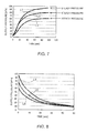
- FIG. 7 is a graph showing characteristics of the supply pressure in the case where the liquid supply unit 50 starts supplying the liquid to the liquid ejection device 20 without carrying out the pre-pressurization processing.
- the blocking unit 60 is constantly in the open state.
- a line L1 shows the supply pressure characteristic in the case where the flow rate Q is set to 6 (ml/min).
- a line L2 shows the supply pressure characteristic in the case where the flow rate Q is set to 5 (ml/min).
- a line L3 shows the supply pressure characteristic in the case where the flow rate Q is set to 4 (ml/min).
- the applied voltage E is set to a predetermined value.
- the steady pressure means the supply pressure with which the liquid is normally supplied at each flow rate Q that is set. As illustrated, it takes 60 to 100 seconds until the liquid is supplied from the liquid supply unit 50 to the liquid ejection device 20 at a desired flow rate Q after the user turns on the foot switch 72.
- the fact that it takes a predetermined time for the supply pressure to reach the steady pressure is considered to be due to various factors such as the channel resistance of the liquid supply channel 56 and the channel deformation (channel expansion) of the liquid supply channel 56 due to elasticity.
- the pre-pressurization control is carried out to adjust the internal pressure of the liquid supply channel 56 to the pre-pressure RP in advance, the time taken for the supply pressure to reach the steady pressure can be reduced when the liquid supply unit 50 starts supplying the liquid to the liquid ejection device 20.
- the pre-pressurized liquid can be supplied when the liquid supply unit 50 supplies the liquid to the liquid ejection device 20. Therefore, the time taken for the supply pressure of the liquid supplied from the liquid supply unit 50 to the liquid ejection device 20 to reach the steady pressure can be reduced. Thus, liquid ejection responsiveness at the time of starting the ejection of the liquid can be improved.
- the medical apparatus system 10 has the table data Tb storing the proper value of the supply pressure SP corresponding to the flow rate Q and the applied voltage E.
- the control unit 70 acquires the pre-pressure RP based on the ejection conditions (flow rate Q and applied voltage E) set by the user and the table data Tb and carries out the pre-pressurization processing. Therefore, in the medical apparatus system 10, the pre-pressurization processing can be carried out with the proper pressure corresponding to the ejection conditions set by the user.
- FIG. 8 is an explanatory view showing attenuation characteristics of the supply pressure in the liquid supply channel 56 in the case where the supply of the liquid from the liquid supply unit 50 is stopped without blocking the channel by the blocking unit 60.
- a line L4 shows the attenuation characteristic of the supply pressure in the liquid supply channel 56 in the case where the supply from the liquid supply unit 50, previously supplying the liquid at the flow rate Q of 6 (ml/min), is stopped.
- Lines L5 and L6 show the attenuation characteristic of the supply pressure in the liquid supply channel 56 in the case where the flow rate Q is 5 (ml/min) and 4 (ml/min), respectively.
- the supply pressure gently attenuates after the liquid supply unit 50 stops the supply of the liquid. Therefore, when the blocking unit 60 does not block the liquid supply channel 56 with the stop of the ejection, the liquid is ejected from the liquid ejection device 20 for a predetermined period even if the user turns off the foot switch 72.
- the blocking unit 60 blocks the channel and therefore responsiveness of the stop of the ejection from the liquid ejection device 20, to the ejection stop operation by the user, can be improved.
- FIG. 9 is an explanatory view illustrating a medical apparatus system 10a including a liquid supply unit 80 which pressurizes a liquid with air pressure.
- the liquid supply unit 80 includes a film pack 81 a pressurizing chamber 82, an air supply channel 83, an air discharge channel 84, a valve 85, a valve 86, and a compressor CM.
- the film pack 81 accommodates a liquid.
- the pressurizing chamber 82 is a chamber for pressurizing the film pack 81 with the air pressure of the air supplied from the air supply channel 83.
- the compressor CM is connected to the air supply channel 83.
- the liquid in the film pack 81 can be pressurized by supplying air to the pressurizing chamber 82 by the compressor CM in the state where the valve 85 is closed. This configuration can also achieve the similar effect to the embodiment.
- FIG. 10 is an explanatory view illustrating a medical apparatus system 10b including a liquid supply unit 90 which pressurizes a liquid with the rotating force of rollers.
- the liquid supply unit 90 includes a film pack 92 and rollers 94, 96.
- the film pack 92 is sandwiched between the rollers 94, 96 and the rollers 94, 96 are rotated, thus pressurizing the liquid in the film pack 92.
- the rollers 94, 96 rotate with the rotating force of a drive motor (not shown). This configuration can also achieve the similar effect to the embodiment.
- the liquid ejection device 20 employs the mechanism in which the liquid inside the housing chamber 38 is provided with pulsation by the piezoelectric element 35.
- the liquid ejection device 20 may employ a mechanism in which a laser beam is cast onto the liquid inside the housing chamber 38 to generate air bubbles, which in turn provide pulsation for the liquid.
- an optical fiber cable for casting a laser beam may be provided in the housing chamber 38.
- the liquid ejection device 20 may employ a mechanism in which an electric heater heats the liquid inside the housing chamber 38 to generate air bubbles, which in turn provide pulsation for the liquid.
- a liquid can be supplied not only to the liquid ejection device but also to various medical apparatuses, such as an ultrasonic surgical knife which ejects a liquid or a contrast medium injection device which injects a contrast medium into a body.
- the control unit 70 carries out pre-pressurization processing, after the liquid supply unit 50 supplies the liquid to the liquid supply channel 56 and the liquid is supplied up to the point in the liquid supply channel 56 that is blocked by the blocking unit 60.
- the pre-pressurization processing may be carried out without supplying the liquid to the liquid supply channel 56 by the liquid supply unit 50.
- the control unit 70 may carry out the pre-pressurization processing after the liquid supply unit 50 supplies the liquid up to the liquid ejection device 20. If the pre-pressurization processing is carried out after the liquid is supplied up to the liquid ejection device 20, the liquid ejection device 20 can be used in a short time after the pre-pressurization processing.
- the table data Tb may be omitted.
- the pre-pressurization processing in which the liquid supply channel 56 is blocked by the blocking unit 60 may be carried out for a predetermined time.
- the supply pressure SP and the pre-pressure RP are described as the same value. However, it is desirable that the pre-pressure RP is 1/5 of the supply pressure SP or above and is equal to or below the supply pressure SP. Since the pre-pressure RP is equal to or below the supply pressure SP, when the liquid ejection device starts ejecting the liquid, safety is secured and the liquid can be stably supplied to the medical apparatus in a short time, due to the pre-pressure RP that is equal to or below the supply pressure SP. It is more desirable that the pre-pressure RP is 1/2 of the supply pressure SP or above and is below the supply pressure SP. Higher safety can be achieved and the liquid can be stably supplied to the medical apparatus in a shorter time.
Landscapes
- Health & Medical Sciences (AREA)
- Life Sciences & Earth Sciences (AREA)
- Surgery (AREA)
- Heart & Thoracic Surgery (AREA)
- Engineering & Computer Science (AREA)
- Biomedical Technology (AREA)
- Nuclear Medicine, Radiotherapy & Molecular Imaging (AREA)
- Medical Informatics (AREA)
- Molecular Biology (AREA)
- Animal Behavior & Ethology (AREA)
- General Health & Medical Sciences (AREA)
- Public Health (AREA)
- Veterinary Medicine (AREA)
- Surgical Instruments (AREA)
- Infusion, Injection, And Reservoir Apparatuses (AREA)
Abstract
Description
- The present invention relates to a technique for supplying a liquid to a medical apparatus.
- The technique of
JP-A-2001-292963 JP-A-2001-292963 - However, the technique of
JP-A-2001-292963 - An advantage of some aspects of the invention is to solve at least a part of the problems described above, and the invention can be implemented as the following forms.
- (1) An aspect of the invention provides a medical apparatus system. The medical apparatus system includes: a medical apparatus having an ejection unit which ejects a liquid; and a liquid supply device which supplies the liquid to the medical apparatus. The liquid supply device includes: a supply channel through which the liquid is supplied to the ej ection unit; a pressurizing unit which pressurizes the liquid in the supply channel; a blocking unit which blocks the supply channel; and a control unit which causes the pressurizing unit to pressurize the liquid in the supply channel in the state where the supply channel is blocked by the blocking unit. According to the medical apparatus system of this configuration, the liquid in the supply channel is pressurized in the state where the supply channel is blocked by the blocking unit. Therefore, when the blocking unit releases the channel, the liquid that is pressurized in advance can be supplied stably to the medical apparatus.
- (2) In the medical apparatus system according to the aspect of the invention described above, the control unit may cause the blocking unit to block the supply channel when the ejection unit stops the ejection. According to the medical apparatus system of this configuration, responsiveness of the stop of ejection can be improved when the ejection unit of the medical apparatus stops the ejection.
- (3) In the medical apparatus system according to the aspect of the invention described above, the medical apparatus system may further include a pressure setting unit which sets a first pressure that is a pressure with which the pressurizing unit pressurizes the liquid when the ejection unit ejects the liquid, and the control unit may set a second pressure that is a pressure with which the pressurizing unit pressurizes the liquid in the supply channel in the state where the supply channel is blocked by the blocking unit, on the basis of the first pressure that is set. According to the medical apparatus system of this configuration, the liquid pressurized with a proper pressure corresponding to the first pressure that is set can be supplied to the medical apparatus.
- (4) In the medical apparatus system according to the aspect of the invention described above, the ejection unit may include an actuator which provides a pulsed flow for the ejected liquid, and an applied voltage setting unit which sets an applied voltage for driving the actuator, and the control unit may set a second pressure that is a pressure with which the pressurizing unit pressurizes the liquid in the supply channel in the state where the supply channel is blocked by the blocking unit, on the basis of the applied voltage that is set. According to the medical apparatus system of this configuration, the liquid pressurized with a proper pressure corresponding to the applied voltage for driving the actuator can be supplied to the medical apparatus.
- (5) Another aspect of the invention provides a liquid supply device which supplies a liquid to a medical apparatus. The liquid supply device includes: a supply channel through which the liquid is supplied to the medical apparatus; a pressurizing unit which pressurizes the liquid in the supply channel; a blocking unit which blocks the supply channel; and a control unit which causes the pressurizing unit to pressurize the liquid in the supply channel in the state where the supply channel is blocked by the blocking unit. According to the liquid supply device of this configuration, the liquid in the supply channel is pressurized in the state where the supply channel is blocked by the blocking unit. Therefore, when the blocking unit releases the channel, the liquid that is pressurized in advance can be supplied stably to the medical apparatus.
- Not all the plural components of each of the above configurations are essential. In order to solve a part or the whole of the foregoing problem or in order to achieve a part or the whole of the advantages described herein, a part of the plural components can be changed, deleted, replaced with another component, or partly deleted in a limited context. Also, in order to solve a part or the whole of the foregoing problem or in order to achieve a part or the whole of the advantages described herein, a part or the whole of the technique features included in one of the above configurations can be combined with a part or the whole of the technical features included in another one of the above configurations, thus forming a separate configuration of the invention.
- For example, as a configuration of the invention, a system including one or more of two components of a medical apparatus and a liquid supply device can be realized. Also, the liquid supply device can be realized as a device including one or more of four components of a supply channel, a pressurizing unit, a blocking unit, and a control unit. That is, the system may or may not include the medical apparatus. The system may or may not include the liquid supply device. The liquid supply device may or may not include the supply channel. The liquid supply device may or may not include the pressurizing unit. The liquid supply device may or may not include the blocking unit. The liquid supply device may or may not include the control unit. The medical apparatus may be configured as a medical apparatus having an ejection unit which ejects a liquid. The liquid supply device may be configured as a liquid supply device which supplies the liquid to the medical apparatus. The supply channel may be configured as a supply channel through which the liquid is supplied to the ejection unit. The pressurizing unit may be configured as a pressurizing unit which pressurizes the liquid in the supply channel. The blocking unit may be configured as a blocking unit which blocks the supply channel. The control unit may be configured as a control unit which causes the pressurizing unit to pressurize the liquid in the supply channel in the state where the supply channel is blocked by the blocking unit. Such a system can be realized, for example, as a medical apparatus system but can also be realized as other system than a medical apparatus system. According to such a configuration, at least one of various problems such as miniaturization of the structure, lower cost, saving of resources, easier manufacturing, and improved user-friendliness can be solved. A part or the whole of the technique features of each configuration of the medical apparatus system can be applied to this system.
- The invention can also be implemented in various other forms other than a system. For example, the invention can be implemented in the form of a liquid supply method, a liquid ejection device, a liquid ejection method, a medical apparatus or the like.
- The invention will be described with reference to the accompanying drawings, wherein like numbers reference like elements.
-
FIG. 1 is an explanatory view showing the configuration of amedical apparatus system 10. -
FIG. 2 is an explanatory view showing a blocking unit. -
FIG. 3 is a flowchart showing the flow of ejection control processing. -
FIGS. 4A to 4C are explanatory views showing table data Tb. -
FIG. 5 shows the result of an experiment showing the relation between applied voltage E and supply pressure SP. -
FIG. 6 is a flowchart showing the flow of pre-pressurization processing. -
FIG. 7 is a graph showing characteristics of supply pressure. -
FIG. 8 is a graph showing attenuation characteristics of supply pressure. -
FIG. 9 is an explanatory view showing amedical apparatus system 10a. -
FIG. 10 is an explanatory view showing amedical apparatus system 10b. -
FIG. 1 is an explanatory view illustrating the configuration of amedical apparatus system 10 as a first embodiment of the invention. Themedical apparatus system 10 is used as a surgical knife which ejects a liquid to an affected part and thus incises or excises the affected part. - The
medical apparatus system 10 includes aliquid ejection device 20 as a medical apparatus, aliquid supply unit 50, and acontrol unit 70. Theliquid ejection device 20 and theliquid supply unit 50 are connected to each other via aliquid supply channel 56. In this embodiment, theliquid supply channel 56 is made of polyvinyl chloride. Theliquid supply channel 56 may also be made of various resins such as silicone or thermoplastic elastomer. A blockingunit 60 is installed on theliquid supply channel 56. Afoot switch 72 and an ejectioncondition setting unit 74 are connected to thecontrol unit 70. Thecontrol unit 70 also stores table data Tb. - The
liquid supply unit 50 supplies a liquid to theliquid ejection device 20. Theliquid supply unit 50 has asyringe 52 and a pressurizingunit 54. Thesyringe 52 accommodates a physiological saline solution as the liquid. As the liquid, various other liquids such as sterilized water for medical use and pure water can also be employed. The pressurizingunit 54 is an actuator which presses thesyringe 52 and thus pressurizes the liquid inside thesyringe 52. In this embodiment, the pressurizingunit 54 has a linear motor. As the linear motor is horizontally driven, thesyringe 52 is pressed and the liquid inside thesyringe 52 is pressurized. The liquid inside thesyringe 52 pressurized by the pressurizingunit 54 is supplied to theliquid ejection device 20 via theliquid supply channel 56. - The
liquid ejection device 20 provides pulsation for the liquid supplied from theliquid supply unit 50 and ejects the pulsed liquid. The user of themedical apparatus system 10 applies the pulsed liquid ejected from theliquid ejection device 20 to an affected part of a patient and thus incises or excises the affected part. - The
liquid ejection device 20 includes afirst case 31, asecond case 32, athird case 33, apiezoelectric element 35, areinforcement board 36, adiaphragm 37, and anejection tube 42. Thefirst case 31 is a cylindrical member. One end of thefirst case 31 is joined to thesecond case 32. The other end of thefirst case 31 is sealed by thethird case 33. Thepiezoelectric element 35 is arranged in the space formed inside thefirst case 31. - The
piezoelectric element 35 is a multilayer piezoelectric element. One end of thepiezoelectric element 35 is fixed to thediaphragm 37 via thereinforcement board 36. The other end of thepiezoelectric element 35 is fixed to thethird case 33. Thediaphragm 37 is made of a metallic thin film and the peripheral edge thereof is fixed to thefirst case 31. Ahousing chamber 38 is formed between thediaphragm 37 and thesecond case 32. Thehousing chamber 38 is changed in volume by the driving of thepiezoelectric element 35. - A
first channel 39 which causes the liquid to flow into thehousing chamber 38 is formed in thesecond case 32. Thefirst channel 39 is connected to theliquid supply channel 56. Also, asecond channel 40 which causes the liquid housed in thehousing chamber 38 to flow out is formed in thesecond case 32. Thesecond channel 40 is connected to theejection tube 42. The operation of theliquid ejection device 20 thus configured is controlled by thecontrol unit 70. - The
control unit 70 controls the operation of the entiremedical apparatus system 10. Thefoot switch 72, which the user operates with a foot, is connected to thecontrol unit 70. As the user turns on thefoot switch 72, thecontrol unit 70 controls theliquid supply unit 50 to supply the liquid to the liquid ejection device 20 (housing chamber 38) and also transmits a drive signal to thepiezoelectric element 35. The liquid supplied from theliquid supply unit 50 flows into thehousing chamber 38 via theliquid supply channel 56 and thefirst channel 39. - As the
piezoelectric element 35 receives the drive signal from thecontrol unit 70, thepiezoelectric element 35 oscillates at a predetermined frequency. As thepiezoelectric element 35 oscillates, the volume of thehousing chamber 38 changes via thediaphragm 37 and the liquid housed in thehousing chamber 38 is pressurized. Pulsation is provided for the liquid pressurized or depressurized at the predetermined frequency. The liquid is ejected outside as a pulsed liquid through thesecond channel 40 and theejection tube 42. - The pulsed liquid refers to a liquid in the state where the flow rate or flow speed varies. The way to eject the liquid in a pulsed form may include intermittent ejection in which ejection and stop are repeated. However, since it suffices that the flow rate or flow speed of the liquid varies, the ejection of the pulsed liquid need not necessarily be intermittent ejection.
- The ejection
condition setting unit 74 for the user to set an ejection condition of the liquid is connected to thecontrol unit 70. The ejectioncondition setting unit 74 includes a flowrate setting unit 76 and an appliedvoltage setting unit 78. - The flow
rate setting unit 76 is a dial-type operation unit for the user to set a flow rate Q (ml/min) of the liquid supplied from theliquid supply unit 50 to theliquid ejection device 20. The appliedvoltage setting unit 78 is a dial-type operation unit for the user to set an applied voltage E (V) of the drive signal transmitted to thepiezoelectric element 35. - The user can adjust the combination of the value of the flow rate Q and the value of the applied voltage E and thus set various ejection conditions of the liquid ejected from the
liquid ejection device 20, such as the ejection pressure, flow rate, and droplet shape of the liquid ejected from theliquid ejection device 20. The ejectioncondition setting unit 74 may also include other operation units than the flowrate setting unit 76 and the appliedvoltage setting unit 78. The ejectioncondition setting unit 74 may include operation units for setting various other ejection conditions, for example, a frequency setting unit for the user to set a frequency of the applied voltage E, and a waveform setting unit for the user to set a waveform of the drive signal, or the like. - The
control unit 70 stores the table data Tb. The table data Tb is a two-dimensional lookup table which outputs a pressure (supply pressure SP) with which theliquid supply unit 50 supplies the liquid, with respect to the two parameters of the flow rate Q and the applied voltage E. The table data Tb will be described in detail later. - The blocking
unit 60 is provided on theliquid supply channel 56. The blockingunit 60 blocks and opens theliquid supply channel 56.FIG. 2 is an explanatory view illustrating the blockingunit 60. As illustrated, the blockingunit 60 haspressing parts 62. Thepressing parts 62 of the blockingunit 60 sandwich and press theliquid supply channel 56 from outside, thus blocking theliquid supply channel 56. In this embodiment, the blockingunit 60 is a solenoid valve. As the blockingunit 60, various other valves capable of blocking theliquid supply unit 50 can be employed, such as a globe valve, ball valve, butterfly valve, or diaphragm valve. The operation of the blockingunit 60 is controlled by thecontrol unit 70. - Next, ejection control processing to control the ejection and stop of the liquid from the
liquid ejection device 20 will be described.FIG. 3 is a flowchart showing the flow of the ejection control processing. The ejection control processing is started as the user turns on the power supply (not shown) of themedical apparatus system 10. - As the ejection control processing is started, the
control unit 70 carries out pre-pressurization processing (Step S110), after theliquid supply unit 50 supplies the liquid to theliquid supply channel 56 and the liquid is supplied to the point in theliquid supply channel 56 to be blocked by the blockingunit 60. The pre-pressurization processing is processing to adjust the internal pressure of theliquid supply channel 56 in advance, in the state where theliquid supply channel 56 is blocked by the blockingunit 60 before the user turns on thefoot switch 72. The pre-pressurization processing will be described in detail later. - As the user turns on the foot switch 72 (Step S130: YES), the
control unit 70 controls the blockingunit 60 to open the liquid supply channel 56 (Step S132). Then, thecontrol unit 70 carries out liquid ejection processing in which the liquid is ej ected from the liquid ejection device 20 (Step S134). Specifically, thecontrol unit 70 controls theliquid supply unit 50 to supply the liquid to the liquid ejection device 20 (housing chamber 38) and also transmits a drive signal to thepiezoelectric element 35. As the liquid ejection processing is executed, the pulsed liquid is ejected from theliquid ejection device 20. The supply pressure SP, which is the pressure with which theliquid supply unit 50 supplies the liquid to theliquid ejection device 20, is determined by thecontrol unit 70, using the flow rate Q, the applied voltage E, and the table data Tb, described below. Theliquid supply unit 50 drives the pressurizingunit 54 under the control of thecontrol unit 70 and supplies the liquid to theliquid ejection device 20 with the supply pressure SP. - As the user turns off the foot switch 72 (Step S136: YES), the
control unit 70 controls the blockingunit 60 to block the liquid supply channel 56 (Step S138). Thecontrol unit 70 repeats the processing of Steps S110 to S138 until the user turns off the power supply of the medical apparatus system 10 (Step S140). - Next, the table data Tb will be described.
FIGS. 4A to 4C are explanatory views illustrating the table data Tb. First, the supply pressure SP (kPa) that is necessary for theliquid supply unit 50 to supply the liquid to theliquid ejection device 20 at the flow rate Q (ml/min) will be described.FIG. 4A is an explanatory view illustrating the relation between the flow rate Q and the supply pressure SP. For example, if the flow rate Q set by the user is 3≤Q<4, theliquid supply unit 50 needs to supply the liquid to theliquid ejection device 20 with the supply pressure SP of about 20 kPa. If the flow rate Q is 4≤Q<5, theliquid supply unit 50 needs to supply the liquid to theliquid ejection device 20 with the supply pressure SP of about 30 kPa. That is, the supply pressure SP needs to be changed according to the magnitude of the flow rate Q. In this embodiment, the relation between the flow rate Q and the supply pressure SP is acquired by actual measurement using themedical apparatus system 10. The relation between the flow rate Q and the supply pressure SP may also be acquired by a simulation. - Next, the applied voltage E (V) and the supply pressure SP (kPa) that is necessary for supplying the liquid to the
liquid ejection device 20 will be described.FIG. 4B is an explanatory view illustrating the relation between the applied voltage E and the supply pressure SP. As shown inFIG. 4B , for example, if the applied voltage E is 0≤E<5 while the flow rate Q is a predetermined constant value, theliquid supply unit 50 needs to supply the liquid to theliquid ejection device 20 with the supply pressure SP of about 50 kPa. If the applied voltage E is 5≤E<10, theliquid supply unit 50 needs to supply the liquid to theliquid ejection device 20 with the supply pressure SP of about 60 kPa. In this embodiment, the relation between the applied voltage E and the supply pressure SP is acquired by actual measurement using themedical apparatus system 10. The relation between the applied voltage E and the supply pressure SP may also be acquired by a simulation. -
FIG. 5 shows the result of an experiment showing the relation between the applied voltage E, the supply pressure SP and the flow rate Q. Plotted points F1 and F2 shown in the graph ofFIG. 5 show experimental values of the supply pressure SP for theliquid supply unit 50 to supply the liquid at each flow rate Q when no voltage is applied to thepiezoelectric element 35. A curve R shows a theoretical value of the supply pressure SP for supplying the liquid at each flow rate Q when no voltage is applied to thepiezoelectric element 35. Plotted points F3 and F4 show values of the supply pressure SP for theliquid supply unit 50 to supply the liquid at each flow rate Q when the applied voltage E is 60 (V). - As can be seen from
FIG. 5 , when the liquid is supplied at a constant flow rate Q from theliquid supply unit 50 to theliquid ejection device 20, the supply pressure SP needs to be changed according to the value of the applied voltage E. As thepiezoelectric element 35 pressurizes the liquid, the liquid inside thefirst channel 39 is pressurized (seeFIG. 1 ). At this point, a force in the opposite direction to the inflow direction acts on the liquid flowing into thefirst channel 39 from theliquid supply channel 56, due to the pressurization of the liquid by thepiezoelectric element 35. Therefore, when the applied voltage E to drive thepiezoelectric element 35 is increased, the supply pressure SP needs to be increased in order to supply the liquid to theliquid ejection device 20 at a constant flow rate Q. -
FIG. 4C is an explanatory view illustrating the table data Tb. As described with reference toFIGS. 4A and 4B , the supply pressure SP needs to be set according to the preset values of the flow rate Q and the applied voltage E. In this embodiment, the proper supply pressure SP corresponding to the two parameters of the flow rate Q and the applied voltage E is recorded in the table data Tb. In this embodiment, the value of the supply pressure SP stored in the table data Tb is acquired by actual measurement using themedical apparatus system 10. The value of the supply pressure SP stored in the table data Tb may also be acquired by a simulation. - When carrying out the ejection control processing, the
control unit 70 inputs the flow rate Q and the applied voltage E that are set via the ejectioncondition setting unit 74, into the table data Tb, and thus acquires the supply pressure SP. Thecontrol unit 70 controls theliquid supply unit 50 to pressurize the liquid with the supply pressure SP acquired from the table data Tb and to supply the liquid to theliquid ejection device 20. - The pre-pressurization processing (Step S110 in
FIG. 3 ) will now be described.FIG. 6 is a flowchart showing the flow of the pre-pressurization processing. As the pre-pressurization processing is started, thecontrol unit 70 controls the blockingunit 60 to block the liquid supply channel 56 (Step S112). Thecontrol unit 70 then acquires the flow rate Q and the applied voltage E that are preset by the user via the ejection condition setting unit 74 (Step S114). - Subsequently, the
control unit 70 determines a pre-pressure RP based on the flow rate Q and the applied voltage E (Step S116). The pre-pressure RP is the internal pressure of theliquid supply channel 56 in the state where theliquid supply channel 56 is blocked by the blockingunit 60. Thecontrol unit 70 inputs the flow rate Q and the applied voltage E set by the user into the table data Tb and determines the supply pressure SP outputted from the table data Tb as the pre-pressure RP. That is, in this embodiment, the supply pressure SP and the pre-pressure RP are the same value. While the pre-pressure RP is acquired using the table data Tb in this embodiment, separate table data for acquiring the pre-pressure RP may also be used. Also, the table data Tb may use table data for acquiring the pre-pressure RP corresponding to each type or device of theliquid ejection device 20, such as the device for incision operation or for endoscope, or corresponding to each type or channel of theliquid supply channel 56, such as the length or diameter of the channel. - After the pre-pressure RP is determined, the internal pressure of the
liquid supply channel 56 is adjusted to the pre-pressure RP (Step S118). Specifically, thecontrol unit 70 drives the pressurizingunit 54 to pressurize the liquid inside thesyringe 52, thus adjusting the internal pressure of theliquid supply channel 56 to the pre-pressure RP. In this description, the pressurizing is not limited to increasing the internal pressure of theliquid supply channel 56 but also includes decreasing the internal pressure of theliquid supply channel 56. Thecontrol unit 70 carries out the pre-pressurization processing in this manner. - The effects of the pre-pressurization processing will be described. First, a comparative example is shown in
FIG. 7. FIG. 7 is a graph showing characteristics of the supply pressure in the case where theliquid supply unit 50 starts supplying the liquid to theliquid ejection device 20 without carrying out the pre-pressurization processing. The blockingunit 60 is constantly in the open state. - A line L1 shows the supply pressure characteristic in the case where the flow rate Q is set to 6 (ml/min). A line L2 shows the supply pressure characteristic in the case where the flow rate Q is set to 5 (ml/min). A line L3 shows the supply pressure characteristic in the case where the flow rate Q is set to 4 (ml/min). The applied voltage E is set to a predetermined value.
- As can be seen from the lines L1 to L3, it takes 60 to 100 seconds for the supply pressure to reach s steady pressure after the
liquid supply unit 50 starts supplying the liquid. The steady pressure means the supply pressure with which the liquid is normally supplied at each flow rate Q that is set. As illustrated, it takes 60 to 100 seconds until the liquid is supplied from theliquid supply unit 50 to theliquid ejection device 20 at a desired flow rate Q after the user turns on thefoot switch 72. The fact that it takes a predetermined time for the supply pressure to reach the steady pressure is considered to be due to various factors such as the channel resistance of theliquid supply channel 56 and the channel deformation (channel expansion) of theliquid supply channel 56 due to elasticity. - In this embodiment, as the pre-pressurization control is carried out to adjust the internal pressure of the
liquid supply channel 56 to the pre-pressure RP in advance, the time taken for the supply pressure to reach the steady pressure can be reduced when theliquid supply unit 50 starts supplying the liquid to theliquid ejection device 20. - As described above, in the
medical apparatus system 10, since the pre-pressurization processing is carried out, the pre-pressurized liquid can be supplied when theliquid supply unit 50 supplies the liquid to theliquid ejection device 20. Therefore, the time taken for the supply pressure of the liquid supplied from theliquid supply unit 50 to theliquid ejection device 20 to reach the steady pressure can be reduced. Thus, liquid ejection responsiveness at the time of starting the ejection of the liquid can be improved. - The
medical apparatus system 10 has the table data Tb storing the proper value of the supply pressure SP corresponding to the flow rate Q and the applied voltage E. Thecontrol unit 70 acquires the pre-pressure RP based on the ejection conditions (flow rate Q and applied voltage E) set by the user and the table data Tb and carries out the pre-pressurization processing. Therefore, in themedical apparatus system 10, the pre-pressurization processing can be carried out with the proper pressure corresponding to the ejection conditions set by the user. - The
control unit 70 causes the blockingunit 60 to block the channel when stopping the ejection of the liquid from theliquid ejection device 20. Therefore, responsiveness of the stop of the liquid ejection can be improved. A comparative example is shown inFIG. 8. FIG. 8 is an explanatory view showing attenuation characteristics of the supply pressure in theliquid supply channel 56 in the case where the supply of the liquid from theliquid supply unit 50 is stopped without blocking the channel by the blockingunit 60. A line L4 shows the attenuation characteristic of the supply pressure in theliquid supply channel 56 in the case where the supply from theliquid supply unit 50, previously supplying the liquid at the flow rate Q of 6 (ml/min), is stopped. Lines L5 and L6 show the attenuation characteristic of the supply pressure in theliquid supply channel 56 in the case where the flow rate Q is 5 (ml/min) and 4 (ml/min), respectively. As can be seen fromFIG. 8 , the supply pressure gently attenuates after theliquid supply unit 50 stops the supply of the liquid. Therefore, when the blockingunit 60 does not block theliquid supply channel 56 with the stop of the ejection, the liquid is ejected from theliquid ejection device 20 for a predetermined period even if the user turns off thefoot switch 72. Meanwhile, in themedical apparatus system 10 of this embodiment, when the user turns off thefoot switch 72, the blockingunit 60 blocks the channel and therefore responsiveness of the stop of the ejection from theliquid ejection device 20, to the ejection stop operation by the user, can be improved. - The invention is not limited to the above embodiment and can be carried out in various other forms without departing from the spirit and scope of the invention. For example, the following modifications can be made.
- In the embodiment, the
liquid supply unit 50 pressurizes the liquid with the pressurizingunit 54 using the linear motor and with thesyringe 52. However, other configurations can also be employed.FIG. 9 is an explanatory view illustrating amedical apparatus system 10a including aliquid supply unit 80 which pressurizes a liquid with air pressure. Theliquid supply unit 80 includes a film pack 81 a pressurizingchamber 82, anair supply channel 83, anair discharge channel 84, avalve 85, avalve 86, and a compressor CM. Thefilm pack 81 accommodates a liquid. The pressurizingchamber 82 is a chamber for pressurizing thefilm pack 81 with the air pressure of the air supplied from theair supply channel 83. The compressor CM is connected to theair supply channel 83. In theliquid supply unit 80, the liquid in thefilm pack 81 can be pressurized by supplying air to the pressurizingchamber 82 by the compressor CM in the state where thevalve 85 is closed. This configuration can also achieve the similar effect to the embodiment. - Another configuration may be employed as the liquid supply unit.
FIG. 10 is an explanatory view illustrating amedical apparatus system 10b including aliquid supply unit 90 which pressurizes a liquid with the rotating force of rollers. As illustrated, theliquid supply unit 90 includes afilm pack 92 androllers liquid supply unit 90, thefilm pack 92 is sandwiched between therollers rollers film pack 92. Therollers - In the embodiment, the
liquid ejection device 20 employs the mechanism in which the liquid inside thehousing chamber 38 is provided with pulsation by thepiezoelectric element 35. As Modification 3, theliquid ejection device 20 may employ a mechanism in which a laser beam is cast onto the liquid inside thehousing chamber 38 to generate air bubbles, which in turn provide pulsation for the liquid. In this case, an optical fiber cable for casting a laser beam may be provided in thehousing chamber 38. Also, theliquid ejection device 20 may employ a mechanism in which an electric heater heats the liquid inside thehousing chamber 38 to generate air bubbles, which in turn provide pulsation for the liquid. Also, a liquid can be supplied not only to the liquid ejection device but also to various medical apparatuses, such as an ultrasonic surgical knife which ejects a liquid or a contrast medium injection device which injects a contrast medium into a body. - In the embodiment, as the ejection control processing is started, the
control unit 70 carries out pre-pressurization processing, after theliquid supply unit 50 supplies the liquid to theliquid supply channel 56 and the liquid is supplied up to the point in theliquid supply channel 56 that is blocked by the blockingunit 60. However, the pre-pressurization processing may be carried out without supplying the liquid to theliquid supply channel 56 by theliquid supply unit 50. Also, thecontrol unit 70 may carry out the pre-pressurization processing after theliquid supply unit 50 supplies the liquid up to theliquid ejection device 20. If the pre-pressurization processing is carried out after the liquid is supplied up to theliquid ejection device 20, theliquid ejection device 20 can be used in a short time after the pre-pressurization processing. - While the table data Tb is used in the embodiment, the table data Tb may be omitted. The pre-pressurization processing in which the
liquid supply channel 56 is blocked by the blockingunit 60 may be carried out for a predetermined time. - In the embodiment, the supply pressure SP and the pre-pressure RP are described as the same value. However, it is desirable that the pre-pressure RP is 1/5 of the supply pressure SP or above and is equal to or below the supply pressure SP. Since the pre-pressure RP is equal to or below the supply pressure SP, when the liquid ejection device starts ejecting the liquid, safety is secured and the liquid can be stably supplied to the medical apparatus in a short time, due to the pre-pressure RP that is equal to or below the supply pressure SP. It is more desirable that the pre-pressure RP is 1/2 of the supply pressure SP or above and is below the supply pressure SP. Higher safety can be achieved and the liquid can be stably supplied to the medical apparatus in a shorter time.
Claims (5)
- A liquid supply device which supplies a liquid to a medical apparatus, the device comprising:a supply channel through which the liquid is supplied to the medical apparatus;a pressurizing unit which pressurizes the liquid in the supply channel;a blocking unit which blocks the supply channel; anda control unit which causes the pressurizing unit to pressurize the liquid in the supply channel in the state where the supply channel is blocked by the blocking unit.
- A medical apparatus system comprising:a medical apparatus having an ejection unit which ejects a liquid; anda liquid supply device according to claim 1 which supplies the liquid to the medical apparatus.
- The medical apparatus system according to claim 2, wherein, the control unit causes the blocking unit to block the supply channel when the ejection unit stops the ejection.
- The medical apparatus system according to claim 2 or 3, further comprising a pressure setting unit which sets a first pressure that is a pressure with which the pressurizing unit pressurizes the liquid when the ejection unit ejects the liquid,
wherein the control unit sets a second pressure that is a pressure with which the pressurizing unit pressurizes the liquid in the supply channel in the state where the supply channel is blocked by the blocking unit, on the basis of the first pressure that is set. - The medical apparatus system according to any one of the preceding claims 1 to 4, wherein the ejection unit includes an actuator which provides a pulsed flow for the ejected liquid, and an applied voltage setting unit which sets an applied voltage for driving the actuator, and
the control unit sets a second pressure that is a pressure with which the pressurizing unit pressurizes the liquid in the supply channel in the state where the supply channel is blocked by the blocking unit, on the basis of the applied voltage that is set.
Applications Claiming Priority (1)
| Application Number | Priority Date | Filing Date | Title |
|---|---|---|---|
| JP2013194886A JP2015058240A (en) | 2013-09-20 | 2013-09-20 | Medical device system and liquid supply device |
Publications (2)
| Publication Number | Publication Date |
|---|---|
| EP2851018A1 true EP2851018A1 (en) | 2015-03-25 |
| EP2851018B1 EP2851018B1 (en) | 2017-02-01 |
Family
ID=51627947
Family Applications (1)
| Application Number | Title | Priority Date | Filing Date |
|---|---|---|---|
| EP14185317.6A Not-in-force EP2851018B1 (en) | 2013-09-20 | 2014-09-18 | Medical apparatus system and liquid supply device |
Country Status (4)
| Country | Link |
|---|---|
| US (1) | US9782194B2 (en) |
| EP (1) | EP2851018B1 (en) |
| JP (1) | JP2015058240A (en) |
| CN (1) | CN104434266A (en) |
Families Citing this family (4)
| Publication number | Priority date | Publication date | Assignee | Title |
|---|---|---|---|---|
| CN106400877B (en) * | 2016-08-30 | 2019-11-12 | 苏州涵轩信息科技有限公司 | A kind of device and method obtaining liquid |
| WO2020004581A1 (en) * | 2018-06-29 | 2020-01-02 | 株式会社サーキュラス | Medicinal liquid injecting device |
| CN109723628B (en) * | 2019-03-01 | 2020-06-19 | 浙江师范大学 | A piezoelectric stack pump |
| JP2021023996A (en) * | 2019-07-31 | 2021-02-22 | セイコーエプソン株式会社 | Liquid jet device |
Citations (5)
| Publication number | Priority date | Publication date | Assignee | Title |
|---|---|---|---|---|
| JP2001292963A (en) | 2000-04-17 | 2001-10-23 | Asahi Optical Co Ltd | Water supply device for body cavity endoscope cleaning |
| US20070129680A1 (en) * | 2003-09-30 | 2007-06-07 | Erbe Elektromedizin Gmbh | Transport device for sterile media |
| JP2010075589A (en) * | 2008-09-29 | 2010-04-08 | Seiko Epson Corp | Fluid injection device, method for controlling the same, and operation device |
| JP2010084564A (en) * | 2008-09-30 | 2010-04-15 | Seiko Epson Corp | Fluid injection device, method for controlling fluid injection device, and surgical appliance |
| US20130138082A1 (en) * | 2010-03-24 | 2013-05-30 | Amr Salahieh | Intravascular Tissue Disruption |
Family Cites Families (26)
| Publication number | Priority date | Publication date | Assignee | Title |
|---|---|---|---|---|
| US5135482A (en) * | 1985-12-31 | 1992-08-04 | Arnold Neracher | Hydrodynamic device for the elimination of an organic deposit obstructing a vessel of a human body |
| CN2213530Y (en) * | 1994-12-22 | 1995-11-29 | 张阳德 | Scalpel with water efflux |
| US5836909A (en) * | 1996-09-13 | 1998-11-17 | Cosmescu; Ioan | Automatic fluid control system for use in open and laparoscopic laser surgery and electrosurgery and method therefor |
| DE20009786U1 (en) * | 2000-05-31 | 2000-10-19 | Taufig, Ahmmed Ziah, Dr., 51109 Köln | Liposuction device |
| US20020116021A1 (en) * | 2000-06-21 | 2002-08-22 | Medjet Inc. | Method and process for generating a high repetition rate pulsed microjet |
| US7509831B2 (en) * | 2007-05-25 | 2009-03-31 | Alcon, Inc. | Method for determining a pressure that corresponds to a flow rate through a check valve |
| JP5115088B2 (en) * | 2007-08-10 | 2013-01-09 | セイコーエプソン株式会社 | Surgical tool |
| JP5293031B2 (en) * | 2008-09-16 | 2013-09-18 | セイコーエプソン株式会社 | Fluid ejecting apparatus and surgical instrument |
| JP5267020B2 (en) * | 2008-09-30 | 2013-08-21 | セイコーエプソン株式会社 | Fluid ejecting apparatus, driving method of fluid ejecting apparatus, and surgical instrument |
| JP4752892B2 (en) * | 2008-09-30 | 2011-08-17 | セイコーエプソン株式会社 | Fluid ejecting apparatus and surgical instrument |
| JP2010082306A (en) * | 2008-10-01 | 2010-04-15 | Seiko Epson Corp | Fluid ejection device, driving method for fluid ejection device, and operating instrument |
| JP2010084678A (en) * | 2008-10-01 | 2010-04-15 | Seiko Epson Corp | Fluid ejection device, fluid ejection method, and operation device |
| JP2010106748A (en) * | 2008-10-30 | 2010-05-13 | Seiko Epson Corp | Fluid ejection system, method for driving fluid ejection system, and surgical apparatus |
| JP4952754B2 (en) * | 2009-08-12 | 2012-06-13 | セイコーエプソン株式会社 | Liquid ejecting apparatus, scalpel for operation, and method for controlling liquid ejecting apparatus |
| JP4788809B2 (en) * | 2009-08-17 | 2011-10-05 | セイコーエプソン株式会社 | Fluid injection method |
| JP5655316B2 (en) * | 2010-02-02 | 2015-01-21 | セイコーエプソン株式会社 | Fluid ejecting apparatus and surgical instrument |
| JP5540760B2 (en) * | 2010-02-22 | 2014-07-02 | セイコーエプソン株式会社 | Liquid ejector |
| JP5609194B2 (en) * | 2010-03-23 | 2014-10-22 | セイコーエプソン株式会社 | Liquid ejector |
| FR2960415B1 (en) * | 2010-05-27 | 2012-12-28 | Nestis | GENERATOR OF HIGH PRESSURE PULSES OF A LIQUID FOR MEDICAL AND SURGICAL APPLICATIONS |
| JP5636811B2 (en) * | 2010-08-20 | 2014-12-10 | セイコーエプソン株式会社 | Liquid ejecting apparatus and medical device using liquid ejecting apparatus |
| JP5614170B2 (en) * | 2010-08-23 | 2014-10-29 | セイコーエプソン株式会社 | Liquid ejecting apparatus and surgical instrument using the liquid ejecting apparatus |
| CN102602142B (en) * | 2011-01-18 | 2016-03-02 | 精工爱普生株式会社 | Liquid injection apparatus |
| CA2860593A1 (en) * | 2012-01-23 | 2013-08-01 | Shifamed Holdings, Llc | Intravascular tissue disruption |
| CN103417265A (en) * | 2012-05-15 | 2013-12-04 | 精工爱普生株式会社 | Medical apparatus |
| EP2732770B1 (en) * | 2012-11-16 | 2016-08-24 | Erbe Elektromedizin GmbH | Needle-free injection device |
| JP6186798B2 (en) * | 2013-03-28 | 2017-08-30 | セイコーエプソン株式会社 | Fluid ejecting apparatus and medical device |
-
2013
- 2013-09-20 JP JP2013194886A patent/JP2015058240A/en not_active Withdrawn
-
2014
- 2014-09-16 CN CN201410472034.0A patent/CN104434266A/en active Pending
- 2014-09-18 EP EP14185317.6A patent/EP2851018B1/en not_active Not-in-force
- 2014-09-19 US US14/490,908 patent/US9782194B2/en not_active Expired - Fee Related
Patent Citations (5)
| Publication number | Priority date | Publication date | Assignee | Title |
|---|---|---|---|---|
| JP2001292963A (en) | 2000-04-17 | 2001-10-23 | Asahi Optical Co Ltd | Water supply device for body cavity endoscope cleaning |
| US20070129680A1 (en) * | 2003-09-30 | 2007-06-07 | Erbe Elektromedizin Gmbh | Transport device for sterile media |
| JP2010075589A (en) * | 2008-09-29 | 2010-04-08 | Seiko Epson Corp | Fluid injection device, method for controlling the same, and operation device |
| JP2010084564A (en) * | 2008-09-30 | 2010-04-15 | Seiko Epson Corp | Fluid injection device, method for controlling fluid injection device, and surgical appliance |
| US20130138082A1 (en) * | 2010-03-24 | 2013-05-30 | Amr Salahieh | Intravascular Tissue Disruption |
Also Published As
| Publication number | Publication date |
|---|---|
| US9782194B2 (en) | 2017-10-10 |
| CN104434266A (en) | 2015-03-25 |
| US20150088176A1 (en) | 2015-03-26 |
| JP2015058240A (en) | 2015-03-30 |
| EP2851018B1 (en) | 2017-02-01 |
Similar Documents
| Publication | Publication Date | Title |
|---|---|---|
| US9592073B2 (en) | Fluid ejection device and method of controlling fluid ejection device | |
| US9655642B2 (en) | Fluid ejection device | |
| EP2851018B1 (en) | Medical apparatus system and liquid supply device | |
| US20150289896A1 (en) | Fluid ejection device | |
| US20140296892A1 (en) | Fluid ejection device and medical apparatus | |
| US9566085B2 (en) | Fluid ejection device | |
| US9248654B2 (en) | Fluid ejection device | |
| US9238373B2 (en) | Fluid ejection device | |
| US20170014149A1 (en) | Liquid Ejection Device and Surgical Apparatus | |
| US9234516B2 (en) | Fluid ejection device and medical device | |
| US20150289895A1 (en) | Fluid ejection device and fluid ejecton method | |
| US9296213B2 (en) | Fluid ejection device | |
| US9561049B2 (en) | Fluid ejection device | |
| US20150238216A1 (en) | Fluid ejecting apparatus and medical device | |
| US20150289897A1 (en) | Fluid ejection device | |
| US9561050B2 (en) | Fluid ejection device | |
| US9204890B2 (en) | Fluid ejection device | |
| US20150293538A1 (en) | Fluid ejection device | |
| US20140296893A1 (en) | Liquid ejection device and medical apparatus | |
| US20150366575A1 (en) | Liquid ejection device |
Legal Events
| Date | Code | Title | Description |
|---|---|---|---|
| PUAI | Public reference made under article 153(3) epc to a published international application that has entered the european phase |
Free format text: ORIGINAL CODE: 0009012 |
|
| 17P | Request for examination filed |
Effective date: 20140918 |
|
| AK | Designated contracting states |
Kind code of ref document: A1 Designated state(s): AL AT BE BG CH CY CZ DE DK EE ES FI FR GB GR HR HU IE IS IT LI LT LU LV MC MK MT NL NO PL PT RO RS SE SI SK SM TR |
|
| AX | Request for extension of the european patent |
Extension state: BA ME |
|
| R17P | Request for examination filed (corrected) |
Effective date: 20150723 |
|
| RBV | Designated contracting states (corrected) |
Designated state(s): AL AT BE BG CH CY CZ DE DK EE ES FI FR GB GR HR HU IE IS IT LI LT LU LV MC MK MT NL NO PL PT RO RS SE SI SK SM TR |
|
| 17Q | First examination report despatched |
Effective date: 20160126 |
|
| GRAP | Despatch of communication of intention to grant a patent |
Free format text: ORIGINAL CODE: EPIDOSNIGR1 |
|
| INTG | Intention to grant announced |
Effective date: 20160819 |
|
| GRAS | Grant fee paid |
Free format text: ORIGINAL CODE: EPIDOSNIGR3 |
|
| RAP1 | Party data changed (applicant data changed or rights of an application transferred) |
Owner name: SEIKO EPSON CORPORATION |
|
| GRAA | (expected) grant |
Free format text: ORIGINAL CODE: 0009210 |
|
| AK | Designated contracting states |
Kind code of ref document: B1 Designated state(s): AL AT BE BG CH CY CZ DE DK EE ES FI FR GB GR HR HU IE IS IT LI LT LU LV MC MK MT NL NO PL PT RO RS SE SI SK SM TR |
|
| REG | Reference to a national code |
Ref country code: GB Ref legal event code: FG4D |
|
| REG | Reference to a national code |
Ref country code: CH Ref legal event code: EP Ref country code: AT Ref legal event code: REF Ref document number: 864892 Country of ref document: AT Kind code of ref document: T Effective date: 20170215 |
|
| REG | Reference to a national code |
Ref country code: IE Ref legal event code: FG4D |
|
| REG | Reference to a national code |
Ref country code: DE Ref legal event code: R096 Ref document number: 602014006510 Country of ref document: DE |
|
| REG | Reference to a national code |
Ref country code: NL Ref legal event code: MP Effective date: 20170201 |
|
| REG | Reference to a national code |
Ref country code: LT Ref legal event code: MG4D |
|
| REG | Reference to a national code |
Ref country code: AT Ref legal event code: MK05 Ref document number: 864892 Country of ref document: AT Kind code of ref document: T Effective date: 20170201 |
|
| PG25 | Lapsed in a contracting state [announced via postgrant information from national office to epo] |
Ref country code: IS Free format text: LAPSE BECAUSE OF FAILURE TO SUBMIT A TRANSLATION OF THE DESCRIPTION OR TO PAY THE FEE WITHIN THE PRESCRIBED TIME-LIMIT Effective date: 20170601 Ref country code: HR Free format text: LAPSE BECAUSE OF FAILURE TO SUBMIT A TRANSLATION OF THE DESCRIPTION OR TO PAY THE FEE WITHIN THE PRESCRIBED TIME-LIMIT Effective date: 20170201 Ref country code: NO Free format text: LAPSE BECAUSE OF FAILURE TO SUBMIT A TRANSLATION OF THE DESCRIPTION OR TO PAY THE FEE WITHIN THE PRESCRIBED TIME-LIMIT Effective date: 20170501 Ref country code: FI Free format text: LAPSE BECAUSE OF FAILURE TO SUBMIT A TRANSLATION OF THE DESCRIPTION OR TO PAY THE FEE WITHIN THE PRESCRIBED TIME-LIMIT Effective date: 20170201 Ref country code: LT Free format text: LAPSE BECAUSE OF FAILURE TO SUBMIT A TRANSLATION OF THE DESCRIPTION OR TO PAY THE FEE WITHIN THE PRESCRIBED TIME-LIMIT Effective date: 20170201 Ref country code: GR Free format text: LAPSE BECAUSE OF FAILURE TO SUBMIT A TRANSLATION OF THE DESCRIPTION OR TO PAY THE FEE WITHIN THE PRESCRIBED TIME-LIMIT Effective date: 20170502 |
|
| PG25 | Lapsed in a contracting state [announced via postgrant information from national office to epo] |
Ref country code: RS Free format text: LAPSE BECAUSE OF FAILURE TO SUBMIT A TRANSLATION OF THE DESCRIPTION OR TO PAY THE FEE WITHIN THE PRESCRIBED TIME-LIMIT Effective date: 20170201 Ref country code: PL Free format text: LAPSE BECAUSE OF FAILURE TO SUBMIT A TRANSLATION OF THE DESCRIPTION OR TO PAY THE FEE WITHIN THE PRESCRIBED TIME-LIMIT Effective date: 20170201 Ref country code: AT Free format text: LAPSE BECAUSE OF FAILURE TO SUBMIT A TRANSLATION OF THE DESCRIPTION OR TO PAY THE FEE WITHIN THE PRESCRIBED TIME-LIMIT Effective date: 20170201 Ref country code: BG Free format text: LAPSE BECAUSE OF FAILURE TO SUBMIT A TRANSLATION OF THE DESCRIPTION OR TO PAY THE FEE WITHIN THE PRESCRIBED TIME-LIMIT Effective date: 20170501 Ref country code: PT Free format text: LAPSE BECAUSE OF FAILURE TO SUBMIT A TRANSLATION OF THE DESCRIPTION OR TO PAY THE FEE WITHIN THE PRESCRIBED TIME-LIMIT Effective date: 20170601 Ref country code: NL Free format text: LAPSE BECAUSE OF FAILURE TO SUBMIT A TRANSLATION OF THE DESCRIPTION OR TO PAY THE FEE WITHIN THE PRESCRIBED TIME-LIMIT Effective date: 20170201 Ref country code: LV Free format text: LAPSE BECAUSE OF FAILURE TO SUBMIT A TRANSLATION OF THE DESCRIPTION OR TO PAY THE FEE WITHIN THE PRESCRIBED TIME-LIMIT Effective date: 20170201 Ref country code: SE Free format text: LAPSE BECAUSE OF FAILURE TO SUBMIT A TRANSLATION OF THE DESCRIPTION OR TO PAY THE FEE WITHIN THE PRESCRIBED TIME-LIMIT Effective date: 20170201 Ref country code: ES Free format text: LAPSE BECAUSE OF FAILURE TO SUBMIT A TRANSLATION OF THE DESCRIPTION OR TO PAY THE FEE WITHIN THE PRESCRIBED TIME-LIMIT Effective date: 20170201 |
|
| REG | Reference to a national code |
Ref country code: FR Ref legal event code: PLFP Year of fee payment: 4 |
|
| PG25 | Lapsed in a contracting state [announced via postgrant information from national office to epo] |
Ref country code: IT Free format text: LAPSE BECAUSE OF FAILURE TO SUBMIT A TRANSLATION OF THE DESCRIPTION OR TO PAY THE FEE WITHIN THE PRESCRIBED TIME-LIMIT Effective date: 20170201 Ref country code: EE Free format text: LAPSE BECAUSE OF FAILURE TO SUBMIT A TRANSLATION OF THE DESCRIPTION OR TO PAY THE FEE WITHIN THE PRESCRIBED TIME-LIMIT Effective date: 20170201 Ref country code: CZ Free format text: LAPSE BECAUSE OF FAILURE TO SUBMIT A TRANSLATION OF THE DESCRIPTION OR TO PAY THE FEE WITHIN THE PRESCRIBED TIME-LIMIT Effective date: 20170201 Ref country code: SK Free format text: LAPSE BECAUSE OF FAILURE TO SUBMIT A TRANSLATION OF THE DESCRIPTION OR TO PAY THE FEE WITHIN THE PRESCRIBED TIME-LIMIT Effective date: 20170201 Ref country code: RO Free format text: LAPSE BECAUSE OF FAILURE TO SUBMIT A TRANSLATION OF THE DESCRIPTION OR TO PAY THE FEE WITHIN THE PRESCRIBED TIME-LIMIT Effective date: 20170201 |
|
| REG | Reference to a national code |
Ref country code: DE Ref legal event code: R097 Ref document number: 602014006510 Country of ref document: DE |
|
| PG25 | Lapsed in a contracting state [announced via postgrant information from national office to epo] |
Ref country code: DK Free format text: LAPSE BECAUSE OF FAILURE TO SUBMIT A TRANSLATION OF THE DESCRIPTION OR TO PAY THE FEE WITHIN THE PRESCRIBED TIME-LIMIT Effective date: 20170201 Ref country code: SM Free format text: LAPSE BECAUSE OF FAILURE TO SUBMIT A TRANSLATION OF THE DESCRIPTION OR TO PAY THE FEE WITHIN THE PRESCRIBED TIME-LIMIT Effective date: 20170201 |
|
| PLBE | No opposition filed within time limit |
Free format text: ORIGINAL CODE: 0009261 |
|
| STAA | Information on the status of an ep patent application or granted ep patent |
Free format text: STATUS: NO OPPOSITION FILED WITHIN TIME LIMIT |
|
| 26N | No opposition filed |
Effective date: 20171103 |
|
| PG25 | Lapsed in a contracting state [announced via postgrant information from national office to epo] |
Ref country code: SI Free format text: LAPSE BECAUSE OF FAILURE TO SUBMIT A TRANSLATION OF THE DESCRIPTION OR TO PAY THE FEE WITHIN THE PRESCRIBED TIME-LIMIT Effective date: 20170201 |
|
| REG | Reference to a national code |
Ref country code: CH Ref legal event code: PL |
|
| PG25 | Lapsed in a contracting state [announced via postgrant information from national office to epo] |
Ref country code: MC Free format text: LAPSE BECAUSE OF FAILURE TO SUBMIT A TRANSLATION OF THE DESCRIPTION OR TO PAY THE FEE WITHIN THE PRESCRIBED TIME-LIMIT Effective date: 20170201 |
|
| REG | Reference to a national code |
Ref country code: IE Ref legal event code: MM4A |
|
| REG | Reference to a national code |
Ref country code: BE Ref legal event code: MM Effective date: 20170930 |
|
| PG25 | Lapsed in a contracting state [announced via postgrant information from national office to epo] |
Ref country code: LU Free format text: LAPSE BECAUSE OF NON-PAYMENT OF DUE FEES Effective date: 20170918 |
|
| PG25 | Lapsed in a contracting state [announced via postgrant information from national office to epo] |
Ref country code: CH Free format text: LAPSE BECAUSE OF NON-PAYMENT OF DUE FEES Effective date: 20170930 Ref country code: LI Free format text: LAPSE BECAUSE OF NON-PAYMENT OF DUE FEES Effective date: 20170930 Ref country code: IE Free format text: LAPSE BECAUSE OF NON-PAYMENT OF DUE FEES Effective date: 20170918 |
|
| REG | Reference to a national code |
Ref country code: FR Ref legal event code: PLFP Year of fee payment: 5 |
|
| PG25 | Lapsed in a contracting state [announced via postgrant information from national office to epo] |
Ref country code: BE Free format text: LAPSE BECAUSE OF NON-PAYMENT OF DUE FEES Effective date: 20170930 |
|
| PG25 | Lapsed in a contracting state [announced via postgrant information from national office to epo] |
Ref country code: MT Free format text: LAPSE BECAUSE OF NON-PAYMENT OF DUE FEES Effective date: 20170918 |
|
| PG25 | Lapsed in a contracting state [announced via postgrant information from national office to epo] |
Ref country code: HU Free format text: LAPSE BECAUSE OF FAILURE TO SUBMIT A TRANSLATION OF THE DESCRIPTION OR TO PAY THE FEE WITHIN THE PRESCRIBED TIME-LIMIT; INVALID AB INITIO Effective date: 20140918 |
|
| PG25 | Lapsed in a contracting state [announced via postgrant information from national office to epo] |
Ref country code: CY Free format text: LAPSE BECAUSE OF FAILURE TO SUBMIT A TRANSLATION OF THE DESCRIPTION OR TO PAY THE FEE WITHIN THE PRESCRIBED TIME-LIMIT Effective date: 20170201 |
|
| PG25 | Lapsed in a contracting state [announced via postgrant information from national office to epo] |
Ref country code: MK Free format text: LAPSE BECAUSE OF FAILURE TO SUBMIT A TRANSLATION OF THE DESCRIPTION OR TO PAY THE FEE WITHIN THE PRESCRIBED TIME-LIMIT Effective date: 20170201 |
|
| PG25 | Lapsed in a contracting state [announced via postgrant information from national office to epo] |
Ref country code: TR Free format text: LAPSE BECAUSE OF FAILURE TO SUBMIT A TRANSLATION OF THE DESCRIPTION OR TO PAY THE FEE WITHIN THE PRESCRIBED TIME-LIMIT Effective date: 20170201 |
|
| PG25 | Lapsed in a contracting state [announced via postgrant information from national office to epo] |
Ref country code: AL Free format text: LAPSE BECAUSE OF FAILURE TO SUBMIT A TRANSLATION OF THE DESCRIPTION OR TO PAY THE FEE WITHIN THE PRESCRIBED TIME-LIMIT Effective date: 20170201 |
|
| PGFP | Annual fee paid to national office [announced via postgrant information from national office to epo] |
Ref country code: GB Payment date: 20230727 Year of fee payment: 10 |
|
| PGFP | Annual fee paid to national office [announced via postgrant information from national office to epo] |
Ref country code: FR Payment date: 20230808 Year of fee payment: 10 Ref country code: DE Payment date: 20230802 Year of fee payment: 10 |
|
| REG | Reference to a national code |
Ref country code: DE Ref legal event code: R119 Ref document number: 602014006510 Country of ref document: DE |
|
| GBPC | Gb: european patent ceased through non-payment of renewal fee |
Effective date: 20240918 |
|
| PG25 | Lapsed in a contracting state [announced via postgrant information from national office to epo] |
Ref country code: DE Free format text: LAPSE BECAUSE OF NON-PAYMENT OF DUE FEES Effective date: 20250401 |
|
| PG25 | Lapsed in a contracting state [announced via postgrant information from national office to epo] |
Ref country code: GB Free format text: LAPSE BECAUSE OF NON-PAYMENT OF DUE FEES Effective date: 20240918 |
|
| PG25 | Lapsed in a contracting state [announced via postgrant information from national office to epo] |
Ref country code: FR Free format text: LAPSE BECAUSE OF NON-PAYMENT OF DUE FEES Effective date: 20240930 |