EP2850955A1 - Battery assembly and electronic cigarette having same - Google Patents
Battery assembly and electronic cigarette having same Download PDFInfo
- Publication number
- EP2850955A1 EP2850955A1 EP14178669.9A EP14178669A EP2850955A1 EP 2850955 A1 EP2850955 A1 EP 2850955A1 EP 14178669 A EP14178669 A EP 14178669A EP 2850955 A1 EP2850955 A1 EP 2850955A1
- Authority
- EP
- European Patent Office
- Prior art keywords
- battery
- aaes
- battery assembly
- end cover
- holder
- Prior art date
- Legal status (The legal status is an assumption and is not a legal conclusion. Google has not performed a legal analysis and makes no representation as to the accuracy of the status listed.)
- Granted
Links
Images



Classifications
-
- A—HUMAN NECESSITIES
- A24—TOBACCO; CIGARS; CIGARETTES; SIMULATED SMOKING DEVICES; SMOKERS' REQUISITES
- A24F—SMOKERS' REQUISITES; MATCH BOXES; SIMULATED SMOKING DEVICES
- A24F40/00—Electrically operated smoking devices; Component parts thereof; Manufacture thereof; Maintenance or testing thereof; Charging means specially adapted therefor
- A24F40/40—Constructional details, e.g. connection of cartridges and battery parts
-
- A—HUMAN NECESSITIES
- A24—TOBACCO; CIGARS; CIGARETTES; SIMULATED SMOKING DEVICES; SMOKERS' REQUISITES
- A24F—SMOKERS' REQUISITES; MATCH BOXES; SIMULATED SMOKING DEVICES
- A24F40/00—Electrically operated smoking devices; Component parts thereof; Manufacture thereof; Maintenance or testing thereof; Charging means specially adapted therefor
- A24F40/90—Arrangements or methods specially adapted for charging batteries thereof
-
- H—ELECTRICITY
- H01—ELECTRIC ELEMENTS
- H01M—PROCESSES OR MEANS, e.g. BATTERIES, FOR THE DIRECT CONVERSION OF CHEMICAL ENERGY INTO ELECTRICAL ENERGY
- H01M50/00—Constructional details or processes of manufacture of the non-active parts of electrochemical cells other than fuel cells, e.g. hybrid cells
- H01M50/20—Mountings; Secondary casings or frames; Racks, modules or packs; Suspension devices; Shock absorbers; Transport or carrying devices; Holders
- H01M50/204—Racks, modules or packs for multiple batteries or multiple cells
- H01M50/207—Racks, modules or packs for multiple batteries or multiple cells characterised by their shape
- H01M50/213—Racks, modules or packs for multiple batteries or multiple cells characterised by their shape adapted for cells having curved cross-section, e.g. round or elliptic
-
- Y—GENERAL TAGGING OF NEW TECHNOLOGICAL DEVELOPMENTS; GENERAL TAGGING OF CROSS-SECTIONAL TECHNOLOGIES SPANNING OVER SEVERAL SECTIONS OF THE IPC; TECHNICAL SUBJECTS COVERED BY FORMER USPC CROSS-REFERENCE ART COLLECTIONS [XRACs] AND DIGESTS
- Y02—TECHNOLOGIES OR APPLICATIONS FOR MITIGATION OR ADAPTATION AGAINST CLIMATE CHANGE
- Y02E—REDUCTION OF GREENHOUSE GAS [GHG] EMISSIONS, RELATED TO ENERGY GENERATION, TRANSMISSION OR DISTRIBUTION
- Y02E60/00—Enabling technologies; Technologies with a potential or indirect contribution to GHG emissions mitigation
- Y02E60/10—Energy storage using batteries
Definitions
- the present invention relates to electronic cigarettes, and particularly to a battery assembly and an electronic cigarette using same.
- a typical electronic cigarette includes an atomizer and a battery assembly for powering the atomizer.
- An air actuating electronic switch (AAES) are widely used in the battery assembly to activate the electronic cigarette when the user sucks the electronic cigarette.
- the AAES is directly assembled into a housing receiving a battery, then an end cover is coupled to an end of the housing, the AAES is fixed by the end cover and the battery. Because the AAES may be pressed directly by the end cover and the battery, welding points of the AAES may become loosened or damaged, and accordingly, the AAES may be damaged.
- the present disclosure relates to an exemplary battery assembly for an electronic cigarette.
- the battery assembly includes a housing, a battery received in the housing, an AAES electrically connected with the battery, an end cover fixed at one end of the housing, and a holder.
- the end cover defines a receiving space.
- the holder includes a bottom wall, a side wall, and a plurality of spaced protruding stages.
- the side wall extends from a first surface of the bottom wall.
- the protruding stages are formed on an opposite second surface of the bottom wall.
- the side wall and the bottom wall cooperatively define an accommodating space.
- the AAES is received in the accommodating space in such a manner that the protruding stages face the battery.
- the holder is received in the receiving space.
- a battery assembly for an electronic cigarette includes a housing 10, a battery 11, an air actuating electronic switch (AAES) 12, a holder 14, and an end cover 13.
- the battery 11 is received in the housing 10, the AAES 12 is electrically connected with the battery 11, the end cover 13 is fixed at one end of the housing 10, and the end cover 13 defines a receiving space 131 (referring to FIG. 4 ).
- the end cover 13 is connected with the housing 10 by interference fit.
- the holder 14 includes a side wall 141, a top wall 142, a bottom wall 143, a through hole 144, a plurality of protruding stages 145, a wire slot 146, an accommodating space 147, and a notch 148.
- the top wall 142 protrudes from the side wall 141 towards a central axis of the holder 14, and defines an opening 149.
- the bottom wall 143 is connected with the side wall 141.
- the through hole 144 is defined in the bottom wall 143.
- the protruding stages 145 surround the through hole 144.
- the accommodating space 147 is defined by the side wall 141 and the bottom wall 143. In the present embodiment, the quantity of the protruding stages 145 is three.
- the protruding stages 145 are configured for keeping the holder 14 spaced away from the battery 11 to form a hollow structure, facilitating the flow of air.
- the holder 14 is made of silica gel, has very good characteristic of buffering, and can provide a buffering when the battery 11 undergoes an external force.
- the AAES 12 includes wires 121 for connecting with the AAES 12 and the battery 11.
- the wires 121 are for powering the AAES 12 via the battery 121.
- the wire slot 146 is configured for guiding the wires 121, and is defined in the side wall 141 of the holder 14.
- the notch 148 defined in the top wall 142 of the holder 14 communicates with the wire slot 146 (as seen in FIG. 3 ), thus improving the airtightness of the battery assembly, thereby enhancing the sensitivity and reliability of the AAES 12.
- the receiving space 131 of the end cover 13 is configured for receiving the holder 14 and the AAES 12.
- the end cover 13 further defines an air inlet 132 for taking in air.
- the AAES 12 is first assembled in the holder 14 via the opening 149 of the top wall 142 to form an integral part. Then the integral part is installed into the receiving space 131. After the assembly is finished, the top wall 142 of the holder 14 faces the bottom of the receiving space 131 of the end cover 13, and the protruding stages 145 on the bottom wall 143 of the holder 14 contact the battery 11.
- the battery assembly further includes an LED 122 (referring to FIG. 1 ) mounted on the AAES 12.
- the LED 122 is for indicating the working state of the battery 11.
- the end cover 13 is made of light-permeable material, so that the working state of the LED 122 can be seen through the end cover 13.
- an electronic cigarette according to a second embodiment includes an atomizer 20 and a battery assembly.
- the atomizer 20 is connected with the battery assembly threadedly.
- the battery assembly is the one as described in the first embodiment.
- the space occupied by the AAES 12 and the holder 14 is reduced.
- a volume of the battery 11 can be increased on the condition that a size of the housing 10 is fixed, thus increasing service time of the battery 11.
- the holder 14 effectively protects the AAES 12, wires 121, and prevents the AAES 12 and the wires 121 from damaging when the battery 11 undergoes an external force. Accordingly, the performance of the battery assembly is improved, and the user experience of the electronic cigarette is also enhanced.
Landscapes
- Chemical & Material Sciences (AREA)
- Chemical Kinetics & Catalysis (AREA)
- Electrochemistry (AREA)
- General Chemical & Material Sciences (AREA)
- Battery Mounting, Suspending (AREA)
Abstract
Description
- The present invention relates to electronic cigarettes, and particularly to a battery assembly and an electronic cigarette using same.
- A typical electronic cigarette includes an atomizer and a battery assembly for powering the atomizer. An air actuating electronic switch (AAES) are widely used in the battery assembly to activate the electronic cigarette when the user sucks the electronic cigarette. Generally, the AAES is directly assembled into a housing receiving a battery, then an end cover is coupled to an end of the housing, the AAES is fixed by the end cover and the battery. Because the AAES may be pressed directly by the end cover and the battery, welding points of the AAES may become loosened or damaged, and accordingly, the AAES may be damaged.
- What is needed, therefore, is a battery assembly and an electronic cigarette using same, which can overcome the above shortcomings.
- The present disclosure relates to an exemplary battery assembly for an electronic cigarette. The battery assembly includes a housing, a battery received in the housing, an AAES electrically connected with the battery, an end cover fixed at one end of the housing, and a holder. The end cover defines a receiving space. The holder includes a bottom wall, a side wall, and a plurality of spaced protruding stages. The side wall extends from a first surface of the bottom wall. The protruding stages are formed on an opposite second surface of the bottom wall. The side wall and the bottom wall cooperatively define an accommodating space. The AAES is received in the accommodating space in such a manner that the protruding stages face the battery. The holder is received in the receiving space.
- Many aspects of the present disclosure can be better understood with reference to the following drawings. The components in the drawings are not necessarily drawn to scale, the emphasis instead being placed upon clearly illustrating the principles of the present disclosure. Moreover, in the drawings, like reference numerals designate corresponding parts throughout the several views.
-
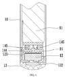
FIG. 1 is a cross-sectional view of a battery assembly according to a first embodiment. -
FIG. 2 is a perspective view of a holder ofFIG. 1 . -
FIG. 3 is another perspective view of the holder ofFIG. 1 , viewed from another angle. -
FIG. 4 is a perspective view of an end cover ofFIG. 1 . -
FIG. 5 is a perspective view showing the end cover, an AAES, and the holder ofFIG. 1 . -
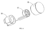
FIG. 6 is another perspective view showing the end cover, an AAES, and the holder ofFIG. 1 , viewed from another angle. -
FIG. 7 is a perspective view of an electronic cigarette according to a second embodiment. - Embodiments of the present disclosure will now be described in detail below and with references to the drawings.
- Referring to
FIG. 1 , a battery assembly for an electronic cigarette, includes ahousing 10, abattery 11, an air actuating electronic switch (AAES) 12, aholder 14, and anend cover 13. Thebattery 11 is received in thehousing 10, theAAES 12 is electrically connected with thebattery 11, theend cover 13 is fixed at one end of thehousing 10, and theend cover 13 defines a receiving space 131 (referring toFIG. 4 ). In the present embodiment, theend cover 13 is connected with thehousing 10 by interference fit. - Referring to
FIGS. 2-3 , theholder 14 includes aside wall 141, atop wall 142, abottom wall 143, a throughhole 144, a plurality of protrudingstages 145, awire slot 146, anaccommodating space 147, and anotch 148. Thetop wall 142 protrudes from theside wall 141 towards a central axis of theholder 14, and defines anopening 149. Thebottom wall 143 is connected with theside wall 141. The throughhole 144 is defined in thebottom wall 143. The protruding stages 145 surround the throughhole 144. Theaccommodating space 147 is defined by theside wall 141 and thebottom wall 143. In the present embodiment, the quantity of the protrudingstages 145 is three. The protruding stages 145 are configured for keeping theholder 14 spaced away from thebattery 11 to form a hollow structure, facilitating the flow of air. Theholder 14 is made of silica gel, has very good characteristic of buffering, and can provide a buffering when thebattery 11 undergoes an external force. - Referring to
FIG. 1 again, theAAES 12 includeswires 121 for connecting with theAAES 12 and thebattery 11. Thewires 121 are for powering theAAES 12 via thebattery 121. Thewire slot 146 is configured for guiding thewires 121, and is defined in theside wall 141 of theholder 14. Thenotch 148 defined in thetop wall 142 of theholder 14 communicates with the wire slot 146 (as seen inFIG. 3 ), thus improving the airtightness of the battery assembly, thereby enhancing the sensitivity and reliability of theAAES 12. - Referring to
FIG. 4 , the receivingspace 131 of theend cover 13 is configured for receiving theholder 14 and theAAES 12. The end cover 13 further defines anair inlet 132 for taking in air. - Referring to
FIGS. 5-6 , in assembly, theAAES 12 is first assembled in theholder 14 via theopening 149 of thetop wall 142 to form an integral part. Then the integral part is installed into the receivingspace 131. After the assembly is finished, thetop wall 142 of theholder 14 faces the bottom of the receivingspace 131 of theend cover 13, and the protrudingstages 145 on thebottom wall 143 of theholder 14 contact thebattery 11. - The battery assembly further includes an LED 122 (referring to
FIG. 1 ) mounted on theAAES 12. TheLED 122 is for indicating the working state of thebattery 11. Preferably, theend cover 13 is made of light-permeable material, so that the working state of theLED 122 can be seen through theend cover 13. - Referring to
FIG. 7 , an electronic cigarette according to a second embodiment includes anatomizer 20 and a battery assembly. Theatomizer 20 is connected with the battery assembly threadedly. The battery assembly is the one as described in the first embodiment. - Because the
AAES 12 and theholder 14 are assembled to form the integral part, and are then received in theend cover 13, the space occupied by the AAES 12 and theholder 14 is reduced. A volume of thebattery 11 can be increased on the condition that a size of thehousing 10 is fixed, thus increasing service time of thebattery 11. Meanwhile, theholder 14 effectively protects theAAES 12,wires 121, and prevents theAAES 12 and thewires 121 from damaging when thebattery 11 undergoes an external force. Accordingly, the performance of the battery assembly is improved, and the user experience of the electronic cigarette is also enhanced. - It is understood that the above-described embodiments are intended to illustrate rather than limit the disclosure. Variations may be made to the embodiments and methods without departing from the spirit of the disclosure. Accordingly, it is appropriate that the appended claims be construed broadly and in a manner consistent with the scope of the disclosure.
Claims (15)
- A battery assembly for an electronic cigarette, comprising:a housing;a battery received in the housing;an air actuating electronic switch (AAES) electrically connected with the battery;an end cover fixed at one end of the housing, the end cover defining a receiving space; anda holder being received in the receiving space, the holder comprising a bottom wall, a side wall, and a plurality of spaced protruding stages, the side wall extending from a first surface of the bottom wall, the protruding stages being formed on an opposite second surface of the bottom wall, the side wall and the bottom wall cooperatively defining an accommodating space, the AAES being received in the accommodating space in such a manner that the protruding stages face the battery.
- The battery assembly of claim 1, wherein the holder further comprises a top wall protruding from the side wall towards a central axis thereof, the top wall defines an opening at a center thereof.
- The battery assembly according to any of claims 1-2, wherein the AAES further comprises wires for connecting the AAES and the battery, the side wall defines a wire slot for accommodating the wires, and the top wall defines a notch communicating with the wire slot.
- The battery assembly according to any of claims 1-3, further comprising an LED mounted on the AAES.
- The battery assembly according to any of claims 1-4, wherein the end cover defines an air inlet.
- The battery assembly according to any of claims 1-5, wherein the end cover is made of light permeable material.
- The battery assembly according to any of claims 1-6, wherein the holder is made of silica gel.
- The battery assembly according to any of claims 1-7, wherein the end cover and the housing are engaged by interference fit.
- The battery assembly according to any of claims 1-8, wherein the total number of the protruding stages is three.
- An electronic cigarette, comprising:an atomizer; anda battery assembly being configured for supplying power to the atomizer, the battery assembly comprising:a housing;a battery received in the housing;an AAES electrically connected with the battery;an end cover fixed at one end of the housing, the end cover defining a receiving space; anda holder being received in the receiving space, the holder comprising a bottom wall, a side wall, and a plurality of spaced protruding stages, the side wall extending from a first surface of the bottom wall, the protruding stages being formed on an opposite second surface of the bottom wall, the side wall and the bottom wall cooperatively defining an accommodating space, the AAES being received in the accommodating space in such a manner that the protruding stages face the battery.
- The electronic cigarette according to claim 10, wherein the holder further comprises a top wall protruding from the side wall towards a central axis thereof, the top wall defines an opening at a center thereof.
- The electronic cigarette according to any of claims 10-11, wherein the AAES further comprises wires for connecting the AAES and the battery, the side wall defines a wire slot for accommodating the wires, and the top wall defines a notch communicating with the wire slot.
- The electronic cigarette according to any of claims 10-12, further comprising an LED mounted on the AAES.
- The electronic cigarette according to any of claims 10-13, wherein the end cover defines an air inlet.
- The electronic cigarette according to any of claims 10-14, wherein the end cover is made of light permeable material.
Applications Claiming Priority (1)
| Application Number | Priority Date | Filing Date | Title |
|---|---|---|---|
| CN201320588244.7U CN203555164U (en) | 2013-09-24 | 2013-09-24 | Battery assembly for electronic cigarette and electronic cigarette |
Publications (2)
| Publication Number | Publication Date |
|---|---|
| EP2850955A1 true EP2850955A1 (en) | 2015-03-25 |
| EP2850955B1 EP2850955B1 (en) | 2018-04-25 |
Family
ID=50504929
Family Applications (1)
| Application Number | Title | Priority Date | Filing Date |
|---|---|---|---|
| EP14178669.9A Active EP2850955B1 (en) | 2013-09-24 | 2014-07-26 | Battery assembly and electronic cigarette having same |
Country Status (4)
| Country | Link |
|---|---|
| US (1) | US10582725B2 (en) |
| EP (1) | EP2850955B1 (en) |
| CN (1) | CN203555164U (en) |
| IN (1) | IN2014DE01997A (en) |
Cited By (1)
| Publication number | Priority date | Publication date | Assignee | Title |
|---|---|---|---|---|
| WO2022034021A1 (en) * | 2020-08-10 | 2022-02-17 | Jt International Sa | Shock absorption in a handheld aerosol generating device |
Families Citing this family (33)
| Publication number | Priority date | Publication date | Assignee | Title |
|---|---|---|---|---|
| US10244793B2 (en) | 2005-07-19 | 2019-04-02 | Juul Labs, Inc. | Devices for vaporization of a substance |
| US10279934B2 (en) | 2013-03-15 | 2019-05-07 | Juul Labs, Inc. | Fillable vaporizer cartridge and method of filling |
| USD747545S1 (en) * | 2013-07-12 | 2016-01-12 | Kimree Hi-Tech Inc | Atomizer |
| USD739599S1 (en) * | 2013-08-01 | 2015-09-22 | Kimree Hi-Tech Inc | Electronic cigarette atomizer |
| USD747546S1 (en) * | 2013-08-05 | 2016-01-12 | Kimree Hi-Tech Inc | Electronic cigarette atomizer |
| USD747547S1 (en) * | 2013-08-06 | 2016-01-12 | Kimree Hi-Tech Inc | Atomizer |
| US10039321B2 (en) | 2013-11-12 | 2018-08-07 | Vmr Products Llc | Vaporizer |
| USD750834S1 (en) * | 2013-11-28 | 2016-03-01 | Hk Triangle Co., Limited | Electronic cigarette |
| US20160366947A1 (en) | 2013-12-23 | 2016-12-22 | James Monsees | Vaporizer apparatus |
| US10076139B2 (en) | 2013-12-23 | 2018-09-18 | Juul Labs, Inc. | Vaporizer apparatus |
| US10058129B2 (en) | 2013-12-23 | 2018-08-28 | Juul Labs, Inc. | Vaporization device systems and methods |
| USD842536S1 (en) | 2016-07-28 | 2019-03-05 | Juul Labs, Inc. | Vaporizer cartridge |
| US10159282B2 (en) | 2013-12-23 | 2018-12-25 | Juul Labs, Inc. | Cartridge for use with a vaporizer device |
| KR102721939B1 (en) | 2013-12-23 | 2024-10-25 | 쥴 랩스, 인크. | Vaporization device systems and methods |
| USD825102S1 (en) | 2016-07-28 | 2018-08-07 | Juul Labs, Inc. | Vaporizer device with cartridge |
| USD756031S1 (en) * | 2014-08-18 | 2016-05-10 | Shenzhen Jieshibo Technology Co., Ltd. | Electronic cigarette |
| USD758650S1 (en) * | 2014-10-16 | 2016-06-07 | Shenzhen Smaco Technology Limited | Electronic cigarette device |
| KR20250012730A (en) | 2014-12-05 | 2025-01-24 | 쥴 랩스, 인크. | Calibrated dose control |
| WO2016101150A1 (en) * | 2014-12-23 | 2016-06-30 | 惠州市吉瑞科技有限公司 | Battery rod, electronic cigarette, and battery rod assembly method |
| USD813445S1 (en) | 2015-07-07 | 2018-03-20 | Nerudia Ltd. | E-cigarette device |
| MX377347B (en) | 2016-02-11 | 2025-03-07 | Juul Labs Inc | Fillable vaporizer cartridge and method of filling |
| MX388616B (en) | 2016-02-11 | 2025-03-20 | Juul Labs Inc | SECURE FITTING CARTRIDGES FOR VAPORIZING DEVICES |
| US10405582B2 (en) | 2016-03-10 | 2019-09-10 | Pax Labs, Inc. | Vaporization device with lip sensing |
| USD849996S1 (en) | 2016-06-16 | 2019-05-28 | Pax Labs, Inc. | Vaporizer cartridge |
| USD851830S1 (en) | 2016-06-23 | 2019-06-18 | Pax Labs, Inc. | Combined vaporizer tamp and pick tool |
| USD848057S1 (en) | 2016-06-23 | 2019-05-07 | Pax Labs, Inc. | Lid for a vaporizer |
| USD836541S1 (en) | 2016-06-23 | 2018-12-25 | Pax Labs, Inc. | Charging device |
| USD827196S1 (en) | 2016-08-04 | 2018-08-28 | Hypofill Limited | Container for holding liquid for refilling an E-cigarette device |
| CN207282560U (en) * | 2017-08-30 | 2018-04-27 | 常州市派腾电子技术服务有限公司 | Battery component and its electronic cigarette |
| USD887632S1 (en) | 2017-09-14 | 2020-06-16 | Pax Labs, Inc. | Vaporizer cartridge |
| CN115428995B (en) * | 2022-09-30 | 2025-04-18 | 爱奇迹(香港)有限公司 | Electronic atomization device |
| USD1024420S1 (en) * | 2022-11-04 | 2024-04-23 | Shenzhen Eigate Technology Co., Ltd. | Electronic cigarette power supply device |
| CN222565091U (en) * | 2024-05-11 | 2025-03-07 | 深圳市合元科技有限公司 | Electronic atomizing device |
Citations (4)
| Publication number | Priority date | Publication date | Assignee | Title |
|---|---|---|---|---|
| US20110304282A1 (en) * | 2010-06-09 | 2011-12-15 | Yonghai Li | Power Supply Device for Electronic Cigarette |
| CN103099319A (en) * | 2013-02-05 | 2013-05-15 | 广东精进能源有限公司 | Electronic cigarette |
| WO2013089551A1 (en) * | 2011-12-15 | 2013-06-20 | Foo Kit Seng | An electronic vaporisation cigarette |
| CN203182017U (en) * | 2013-03-21 | 2013-09-11 | 深圳市康泓威科技有限公司 | Electronic cigarette |
Family Cites Families (5)
| Publication number | Priority date | Publication date | Assignee | Title |
|---|---|---|---|---|
| ES2425780T3 (en) * | 2007-06-15 | 2013-10-17 | Panasonic Corporation | Wireless communication device and response signal broadcast procedure |
| WO2013141907A1 (en) * | 2012-03-23 | 2013-09-26 | Njoy, Inc. | Electronic cigarette configured to simulate the natural burn of a traditional cigarette |
| CN203776160U (en) * | 2012-06-20 | 2014-08-20 | 惠州市吉瑞科技有限公司 | Electronic cigarette and electronic cigarette device |
| KR20150012253A (en) * | 2012-07-23 | 2015-02-03 | 킴르 하이테크 인코퍼레이티드 | Electronic cigarette |
| WO2014134778A1 (en) * | 2013-03-04 | 2014-09-12 | Liu Qiuming | Electronic cigarette |
-
2013
- 2013-09-24 CN CN201320588244.7U patent/CN203555164U/en not_active Expired - Lifetime
-
2014
- 2014-07-16 IN IN1997DE2014 patent/IN2014DE01997A/en unknown
- 2014-07-24 US US14/340,555 patent/US10582725B2/en active Active
- 2014-07-26 EP EP14178669.9A patent/EP2850955B1/en active Active
Patent Citations (4)
| Publication number | Priority date | Publication date | Assignee | Title |
|---|---|---|---|---|
| US20110304282A1 (en) * | 2010-06-09 | 2011-12-15 | Yonghai Li | Power Supply Device for Electronic Cigarette |
| WO2013089551A1 (en) * | 2011-12-15 | 2013-06-20 | Foo Kit Seng | An electronic vaporisation cigarette |
| CN103099319A (en) * | 2013-02-05 | 2013-05-15 | 广东精进能源有限公司 | Electronic cigarette |
| CN203182017U (en) * | 2013-03-21 | 2013-09-11 | 深圳市康泓威科技有限公司 | Electronic cigarette |
Cited By (1)
| Publication number | Priority date | Publication date | Assignee | Title |
|---|---|---|---|---|
| WO2022034021A1 (en) * | 2020-08-10 | 2022-02-17 | Jt International Sa | Shock absorption in a handheld aerosol generating device |
Also Published As
| Publication number | Publication date |
|---|---|
| IN2014DE01997A (en) | 2015-06-26 |
| US10582725B2 (en) | 2020-03-10 |
| US20150083145A1 (en) | 2015-03-26 |
| EP2850955B1 (en) | 2018-04-25 |
| CN203555164U (en) | 2014-04-23 |
Similar Documents
| Publication | Publication Date | Title |
|---|---|---|
| US10582725B2 (en) | Battery assembly and electronic cigarette having same | |
| US9414628B2 (en) | Electronic cigarette | |
| EP2954791A1 (en) | Atomizer and electronic cigarette having same | |
| US20170006920A1 (en) | Battery rod and electronic cigarette | |
| CN203762298U (en) | Power supply device for electronic cigarette and electronic cigarette | |
| EP2894695A3 (en) | A battery cell connecting board | |
| WO2008093739A1 (en) | Connector | |
| EP2017892A3 (en) | Light emitting device and method of manufacturing the same | |
| CN205066981U (en) | Pressure sensor | |
| CN203703874U (en) | Direct-inserting small connector and LED lamp utilizing the same | |
| CN103349364A (en) | Button-type electronic cigarette, button switch and battery pack | |
| CN104055226B (en) | Wireless electronic cigarette | |
| JP2020061252A5 (en) | ||
| JP2011513956A5 (en) | ||
| RU2014125563A (en) | FOUR-POLE PLUG FOR CONNECTION WITH PRINTED INSTALLATION BOARD | |
| US20170054242A1 (en) | Electrical connector having improved contacts | |
| US20170130913A1 (en) | Laser pointer | |
| CN100530846C (en) | Power source outlet device | |
| JP2006352064A5 (en) | ||
| TWM373046U (en) | Electrical connector | |
| CN201570650U (en) | Probe type connector | |
| ATE417386T1 (en) | CONNECTION COVER | |
| TW200733494A (en) | Electrical connector assembly | |
| CN203521249U (en) | Button switch | |
| CN201904472U (en) | Sealing socket |
Legal Events
| Date | Code | Title | Description |
|---|---|---|---|
| PUAI | Public reference made under article 153(3) epc to a published international application that has entered the european phase |
Free format text: ORIGINAL CODE: 0009012 |
|
| 17P | Request for examination filed |
Effective date: 20140905 |
|
| AK | Designated contracting states |
Kind code of ref document: A1 Designated state(s): AL AT BE BG CH CY CZ DE DK EE ES FI FR GB GR HR HU IE IS IT LI LT LU LV MC MK MT NL NO PL PT RO RS SE SI SK SM TR |
|
| AX | Request for extension of the european patent |
Extension state: BA ME |
|
| RIC1 | Information provided on ipc code assigned before grant |
Ipc: H01M 2/10 20060101ALI20170825BHEP Ipc: A24F 47/00 20060101AFI20170825BHEP |
|
| GRAP | Despatch of communication of intention to grant a patent |
Free format text: ORIGINAL CODE: EPIDOSNIGR1 |
|
| INTG | Intention to grant announced |
Effective date: 20171110 |
|
| GRAA | (expected) grant |
Free format text: ORIGINAL CODE: 0009210 |
|
| GRAS | Grant fee paid |
Free format text: ORIGINAL CODE: EPIDOSNIGR3 |
|
| AK | Designated contracting states |
Kind code of ref document: B1 Designated state(s): AL AT BE BG CH CY CZ DE DK EE ES FI FR GB GR HR HU IE IS IT LI LT LU LV MC MK MT NL NO PL PT RO RS SE SI SK SM TR |
|
| REG | Reference to a national code |
Ref country code: GB Ref legal event code: FG4D |
|
| REG | Reference to a national code |
Ref country code: CH Ref legal event code: EP |
|
| REG | Reference to a national code |
Ref country code: AT Ref legal event code: REF Ref document number: 991874 Country of ref document: AT Kind code of ref document: T Effective date: 20180515 |
|
| REG | Reference to a national code |
Ref country code: IE Ref legal event code: FG4D |
|
| REG | Reference to a national code |
Ref country code: DE Ref legal event code: R096 Ref document number: 602014024325 Country of ref document: DE |
|
| REG | Reference to a national code |
Ref country code: FR Ref legal event code: PLFP Year of fee payment: 5 Ref country code: NL Ref legal event code: FP |
|
| REG | Reference to a national code |
Ref country code: LT Ref legal event code: MG4D |
|
| PG25 | Lapsed in a contracting state [announced via postgrant information from national office to epo] |
Ref country code: FI Free format text: LAPSE BECAUSE OF FAILURE TO SUBMIT A TRANSLATION OF THE DESCRIPTION OR TO PAY THE FEE WITHIN THE PRESCRIBED TIME-LIMIT Effective date: 20180425 Ref country code: BG Free format text: LAPSE BECAUSE OF FAILURE TO SUBMIT A TRANSLATION OF THE DESCRIPTION OR TO PAY THE FEE WITHIN THE PRESCRIBED TIME-LIMIT Effective date: 20180725 Ref country code: PL Free format text: LAPSE BECAUSE OF FAILURE TO SUBMIT A TRANSLATION OF THE DESCRIPTION OR TO PAY THE FEE WITHIN THE PRESCRIBED TIME-LIMIT Effective date: 20180425 Ref country code: NO Free format text: LAPSE BECAUSE OF FAILURE TO SUBMIT A TRANSLATION OF THE DESCRIPTION OR TO PAY THE FEE WITHIN THE PRESCRIBED TIME-LIMIT Effective date: 20180725 Ref country code: LT Free format text: LAPSE BECAUSE OF FAILURE TO SUBMIT A TRANSLATION OF THE DESCRIPTION OR TO PAY THE FEE WITHIN THE PRESCRIBED TIME-LIMIT Effective date: 20180425 Ref country code: ES Free format text: LAPSE BECAUSE OF FAILURE TO SUBMIT A TRANSLATION OF THE DESCRIPTION OR TO PAY THE FEE WITHIN THE PRESCRIBED TIME-LIMIT Effective date: 20180425 Ref country code: SE Free format text: LAPSE BECAUSE OF FAILURE TO SUBMIT A TRANSLATION OF THE DESCRIPTION OR TO PAY THE FEE WITHIN THE PRESCRIBED TIME-LIMIT Effective date: 20180425 |
|
| PG25 | Lapsed in a contracting state [announced via postgrant information from national office to epo] |
Ref country code: LV Free format text: LAPSE BECAUSE OF FAILURE TO SUBMIT A TRANSLATION OF THE DESCRIPTION OR TO PAY THE FEE WITHIN THE PRESCRIBED TIME-LIMIT Effective date: 20180425 Ref country code: GR Free format text: LAPSE BECAUSE OF FAILURE TO SUBMIT A TRANSLATION OF THE DESCRIPTION OR TO PAY THE FEE WITHIN THE PRESCRIBED TIME-LIMIT Effective date: 20180726 Ref country code: HR Free format text: LAPSE BECAUSE OF FAILURE TO SUBMIT A TRANSLATION OF THE DESCRIPTION OR TO PAY THE FEE WITHIN THE PRESCRIBED TIME-LIMIT Effective date: 20180425 Ref country code: RS Free format text: LAPSE BECAUSE OF FAILURE TO SUBMIT A TRANSLATION OF THE DESCRIPTION OR TO PAY THE FEE WITHIN THE PRESCRIBED TIME-LIMIT Effective date: 20180425 |
|
| REG | Reference to a national code |
Ref country code: AT Ref legal event code: MK05 Ref document number: 991874 Country of ref document: AT Kind code of ref document: T Effective date: 20180425 |
|
| PG25 | Lapsed in a contracting state [announced via postgrant information from national office to epo] |
Ref country code: PT Free format text: LAPSE BECAUSE OF FAILURE TO SUBMIT A TRANSLATION OF THE DESCRIPTION OR TO PAY THE FEE WITHIN THE PRESCRIBED TIME-LIMIT Effective date: 20180827 |
|
| REG | Reference to a national code |
Ref country code: DE Ref legal event code: R097 Ref document number: 602014024325 Country of ref document: DE |
|
| PG25 | Lapsed in a contracting state [announced via postgrant information from national office to epo] |
Ref country code: CZ Free format text: LAPSE BECAUSE OF FAILURE TO SUBMIT A TRANSLATION OF THE DESCRIPTION OR TO PAY THE FEE WITHIN THE PRESCRIBED TIME-LIMIT Effective date: 20180425 Ref country code: RO Free format text: LAPSE BECAUSE OF FAILURE TO SUBMIT A TRANSLATION OF THE DESCRIPTION OR TO PAY THE FEE WITHIN THE PRESCRIBED TIME-LIMIT Effective date: 20180425 Ref country code: SK Free format text: LAPSE BECAUSE OF FAILURE TO SUBMIT A TRANSLATION OF THE DESCRIPTION OR TO PAY THE FEE WITHIN THE PRESCRIBED TIME-LIMIT Effective date: 20180425 Ref country code: EE Free format text: LAPSE BECAUSE OF FAILURE TO SUBMIT A TRANSLATION OF THE DESCRIPTION OR TO PAY THE FEE WITHIN THE PRESCRIBED TIME-LIMIT Effective date: 20180425 Ref country code: AT Free format text: LAPSE BECAUSE OF FAILURE TO SUBMIT A TRANSLATION OF THE DESCRIPTION OR TO PAY THE FEE WITHIN THE PRESCRIBED TIME-LIMIT Effective date: 20180425 Ref country code: DK Free format text: LAPSE BECAUSE OF FAILURE TO SUBMIT A TRANSLATION OF THE DESCRIPTION OR TO PAY THE FEE WITHIN THE PRESCRIBED TIME-LIMIT Effective date: 20180425 |
|
| PG25 | Lapsed in a contracting state [announced via postgrant information from national office to epo] |
Ref country code: SM Free format text: LAPSE BECAUSE OF FAILURE TO SUBMIT A TRANSLATION OF THE DESCRIPTION OR TO PAY THE FEE WITHIN THE PRESCRIBED TIME-LIMIT Effective date: 20180425 |
|
| PLBE | No opposition filed within time limit |
Free format text: ORIGINAL CODE: 0009261 |
|
| STAA | Information on the status of an ep patent application or granted ep patent |
Free format text: STATUS: NO OPPOSITION FILED WITHIN TIME LIMIT |
|
| PG25 | Lapsed in a contracting state [announced via postgrant information from national office to epo] |
Ref country code: MC Free format text: LAPSE BECAUSE OF FAILURE TO SUBMIT A TRANSLATION OF THE DESCRIPTION OR TO PAY THE FEE WITHIN THE PRESCRIBED TIME-LIMIT Effective date: 20180425 Ref country code: LU Free format text: LAPSE BECAUSE OF NON-PAYMENT OF DUE FEES Effective date: 20180726 |
|
| REG | Reference to a national code |
Ref country code: BE Ref legal event code: MM Effective date: 20180731 |
|
| 26N | No opposition filed |
Effective date: 20190128 |
|
| PG25 | Lapsed in a contracting state [announced via postgrant information from national office to epo] |
Ref country code: SI Free format text: LAPSE BECAUSE OF FAILURE TO SUBMIT A TRANSLATION OF THE DESCRIPTION OR TO PAY THE FEE WITHIN THE PRESCRIBED TIME-LIMIT Effective date: 20180425 Ref country code: BE Free format text: LAPSE BECAUSE OF NON-PAYMENT OF DUE FEES Effective date: 20180731 |
|
| PG25 | Lapsed in a contracting state [announced via postgrant information from national office to epo] |
Ref country code: AL Free format text: LAPSE BECAUSE OF FAILURE TO SUBMIT A TRANSLATION OF THE DESCRIPTION OR TO PAY THE FEE WITHIN THE PRESCRIBED TIME-LIMIT Effective date: 20180425 |
|
| PG25 | Lapsed in a contracting state [announced via postgrant information from national office to epo] |
Ref country code: MT Free format text: LAPSE BECAUSE OF NON-PAYMENT OF DUE FEES Effective date: 20180726 |
|
| PG25 | Lapsed in a contracting state [announced via postgrant information from national office to epo] |
Ref country code: TR Free format text: LAPSE BECAUSE OF FAILURE TO SUBMIT A TRANSLATION OF THE DESCRIPTION OR TO PAY THE FEE WITHIN THE PRESCRIBED TIME-LIMIT Effective date: 20180425 |
|
| PG25 | Lapsed in a contracting state [announced via postgrant information from national office to epo] |
Ref country code: HU Free format text: LAPSE BECAUSE OF FAILURE TO SUBMIT A TRANSLATION OF THE DESCRIPTION OR TO PAY THE FEE WITHIN THE PRESCRIBED TIME-LIMIT; INVALID AB INITIO Effective date: 20140726 |
|
| PG25 | Lapsed in a contracting state [announced via postgrant information from national office to epo] |
Ref country code: MK Free format text: LAPSE BECAUSE OF NON-PAYMENT OF DUE FEES Effective date: 20180425 Ref country code: CY Free format text: LAPSE BECAUSE OF FAILURE TO SUBMIT A TRANSLATION OF THE DESCRIPTION OR TO PAY THE FEE WITHIN THE PRESCRIBED TIME-LIMIT Effective date: 20180425 |
|
| PG25 | Lapsed in a contracting state [announced via postgrant information from national office to epo] |
Ref country code: IS Free format text: LAPSE BECAUSE OF FAILURE TO SUBMIT A TRANSLATION OF THE DESCRIPTION OR TO PAY THE FEE WITHIN THE PRESCRIBED TIME-LIMIT Effective date: 20180825 |
|
| P01 | Opt-out of the competence of the unified patent court (upc) registered |
Free format text: CASE NUMBER: APP_3670/2025 Effective date: 20250122 |
|
| PGFP | Annual fee paid to national office [announced via postgrant information from national office to epo] |
Ref country code: NL Payment date: 20250630 Year of fee payment: 12 |
|
| PGFP | Annual fee paid to national office [announced via postgrant information from national office to epo] |
Ref country code: IE Payment date: 20250620 Year of fee payment: 12 |
|
| PGFP | Annual fee paid to national office [announced via postgrant information from national office to epo] |
Ref country code: DE Payment date: 20250711 Year of fee payment: 12 |
|
| PGFP | Annual fee paid to national office [announced via postgrant information from national office to epo] |
Ref country code: IT Payment date: 20250714 Year of fee payment: 12 |
|
| PGFP | Annual fee paid to national office [announced via postgrant information from national office to epo] |
Ref country code: GB Payment date: 20250723 Year of fee payment: 12 |
|
| PGFP | Annual fee paid to national office [announced via postgrant information from national office to epo] |
Ref country code: FR Payment date: 20250730 Year of fee payment: 12 |
|
| PGFP | Annual fee paid to national office [announced via postgrant information from national office to epo] |
Ref country code: CH Payment date: 20250801 Year of fee payment: 12 |