EP2850623B1 - Multiple terminals bushing assembly - Google Patents
Multiple terminals bushing assembly Download PDFInfo
- Publication number
- EP2850623B1 EP2850623B1 EP12721278.5A EP12721278A EP2850623B1 EP 2850623 B1 EP2850623 B1 EP 2850623B1 EP 12721278 A EP12721278 A EP 12721278A EP 2850623 B1 EP2850623 B1 EP 2850623B1
- Authority
- EP
- European Patent Office
- Prior art keywords
- bushing assembly
- bolts
- bushing
- transformer
- press plates
- Prior art date
- Legal status (The legal status is an assumption and is not a legal conclusion. Google has not performed a legal analysis and makes no representation as to the accuracy of the status listed.)
- Active
Links
Images


Classifications
-
- H—ELECTRICITY
- H01—ELECTRIC ELEMENTS
- H01F—MAGNETS; INDUCTANCES; TRANSFORMERS; SELECTION OF MATERIALS FOR THEIR MAGNETIC PROPERTIES
- H01F27/00—Details of transformers or inductances, in general
- H01F27/02—Casings
- H01F27/04—Leading of conductors or axles through casings, e.g. for tap-changing arrangements
Definitions
- the present invention relates to a multiple terminals bushing assembly for electrical transformer.
- Transformers are used to distribute electricity from the point of generation or substations for domestic home or business and thereby stepping down the voltage.
- Transformers require insulative conductors on both the high and low voltage sides.
- the transformer case or tank is usually metal and must be safely insulated.
- a bushing is a hollow isolator, carrying high and low voltage leads through a wall portion of the tank.
- Low voltage bushings of tank-type transformers are generally made up of molded epoxy bushing or multi-piece assemblies with porcelain isolators. Mounting space of a bushing assembly is restricted by outer dimensions, creepage distance and clearance distance between the terminals.
- the bushing compartment of electrical transformers is arranged on the top portion of the transformer tank.
- the tank is hermetically sealed by placing a sealing gasket between the top portion, usually a flat cover, and a pot-shaped casing portion.
- the bushing compartment comprises electrically insulated conductors extending through an opening of the tank and having substantial vertical oriented outer terminals. Electrical connection of the terminals is easily possible with the bushing compartment arranged on the top of the tank.
- the bushing assembly according to the invention has two press plates which serve as an insulation support for the connector elements.
- the space required for large amount of bushings is reduced.
- Susceptibility to variations and modifications for specific applications e.g. simple implementation of additional connector elements and easy rearrangement for specific applications, various connector elements having different cross-sections and shapes implemented in one bushing assembly.
- Low cost is achieved by the unsophisticated machining and assembly technology and by the availability of the raw materials on the market.
- the ring-shaped gasket is arranged in a ring-shaped recess provided in at least one of the press plates and serve as a seal to prevent fluid leakage around the connector elements.
- the clamping arrangement comprises a first set of bolts to hold together the press plates during the pre-assembly of the transformer's active part.
- the first set of bolts are arranged in counterbored holes provided in the upper press plate averted form the transformer casing to leave clearance between the bolt head and clamping frame and screwed in threaded blind holes in the lower press plate to prevent the fluid flow through the hole.
- the clamping arrangement further comprises a clamping frame and second set of bolts, whereby the pair of press plates is sandwiched between the clamping frame and the transformer casing.
- a sealing plate is arranged between the transformer casing and the opposing press plate.
- the second set of bolts to be introduced form the exterior of the transformer casing in order to pull the clamping frame towards the tank and squeeze the sealing gaskets around the connector elements.
- the second bolts are flange-type bolts and sealing between the tank wall and the bolt is accomplished by a gasket, whereby a washer limits the squeezing of the gasket.
- each of the connector elements is coated with a sealant compound.
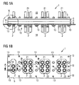
- Fig. 1a shows a front view of bushing assembly 1 of a tank-type electrical transformer having multiple low voltage bushings per phase.
- the transformer tank 6 has an opening 15.
- the bushing assembly 1 is arranged in this opening 15.
- the bushing assembly 1 comprises multiple connector elements 2, 21 made of conductive material.
- the connector elements 2,21 are adapted for connection of electrical conductors.
- the bushing assembly 1 further comprises one upper and one lower machined press plates 3, 4. Both press plates 3, 4 are closely spaced and made of an insulation material. Each press plate 3, 4 show through holes 12 ( Fig. 3 ) for guiding the connector elements 2, 21 between the exterior 18 and the interior 19 of the transformer tank 6.
- the press plates 3, 4 are sandwiched between a clamping frame 5 ( Fig. 4 ) and the transformer tank 6.
- a sealing plate 8 ( Fig. 5 ) is located between the lower press plate 4 and the tank 6.
- the clamping frame 5 and the sealing plate 8 have openings 22, 23.
- Fig. 1b shows a top view of the bushing assembly 1.
- Each phase comprises six connector elements 2 and one connector element 21.
- the connector elements 2,21 of each phase arranged in the openings 22, 23 of the clamping frame 5 and sealing plate 8(three rows, with two connector elements in each row).
- Fig. 2b shows two connector element types made of conductive material used for different ampacities.
- the electrical conductor is inserted into the ending of the tubular part of the connector element and electrically connected using crimp connection.
- FIG. 3 shows partially in section the area around the through holes in the upper press plate and countersunk holes in the lower press plate 12 according to lines A-A and B-B in Figure 2 .
- the clamping arrangement comprises first bolts 17 to pull together plates 3 and 4.
- the upper press plate has counterbored holes 10 for the head of bolt 17.
- the lower press plate 4 has threaded blind holes 11. With the bolts 17 the press plates 3, 4 are compressed and held in a closely spaced position. Fluid leakage is prevented by the sealing gaskets 7, which are provided in countersunk holes 16 in the lower plate 4, squeezed by pulling the plates 3, 4 together and by a sealing plate 8 between the transformer tank 6 and the lower plate 4.
- the curved surface area of each of the connector elements 2, 21 is coated with a sealant compound. Retaining rings 20 are inserted in the groove on connector element 2 to prevent the slip out from the press plates.
- the final clamping is furnished by compressing the sealing gaskets 7 between the press plates 3, 4 around the connector elements with the steel clamping frame 5.
- the clamping bolts 13 are introduced from the outer side (exterior 18). This facilitates the assembly process.
- an o-ring 9 ( Fig. 6 ) is placed between the flanged clamping bolt and the washer 14 ( Fig. 6 ).
- Fig. 7 and Fig. 8 show the bushing assembly 1 according to the invention located on the bottom part of a bushing compartment 24.
- the bushing compartment 24 is attached to a side wall 25 of a transformer tank. This design allows the arrangement of bushings in two levels: the high voltage side on the top of the transformer, the low voltage multiple terminals on the bottom portion 26 of a separate bushing compartment 24.
- the two-level construction of a bushing assembly opens the possibility for arrangement of further connection means required in high current applications. Electrical terminals 2, 21 facing downwardly from the bottom portion 26 of the bushing compartment 24 are protected in a niche.
- the invention provides sufficient space for electrical connection required in additional high current applications.
Landscapes
- Engineering & Computer Science (AREA)
- Power Engineering (AREA)
- Housings And Mounting Of Transformers (AREA)
Description
- The present invention relates to a multiple terminals bushing assembly for electrical transformer.
- Electrical transformers are used to distribute electricity from the point of generation or substations for domestic home or business and thereby stepping down the voltage. Transformers require insulative conductors on both the high and low voltage sides. The transformer case or tank is usually metal and must be safely insulated. A bushing is a hollow isolator, carrying high and low voltage leads through a wall portion of the tank.
- Low voltage bushings of tank-type transformers are generally made up of molded epoxy bushing or multi-piece assemblies with porcelain isolators. Mounting space of a bushing assembly is restricted by outer dimensions, creepage distance and clearance distance between the terminals.
- Traditionally, the bushing compartment of electrical transformers, especially distribution transformers, is arranged on the top portion of the transformer tank. The tank is hermetically sealed by placing a sealing gasket between the top portion, usually a flat cover, and a pot-shaped casing portion. The bushing compartment comprises electrically insulated conductors extending through an opening of the tank and having substantial vertical oriented outer terminals. Electrical connection of the terminals is easily possible with the bushing compartment arranged on the top of the tank.
- However, in applications where additional high current connection is required the available space on the top portion of the tank is limiting factor. The required space for multiple bushings per phase will increase the outer dimensions of the transformer. It is common practice to place the bushings on the cover of the transformer in single or multiple rows making the connection to the control unit grid difficult. A further disadvantage is, that such an low voltage bushing arrangement is not easy to adapt on various modifications for specific applications.
- Thus, it would be desirable to provide a multiple terminals bushing assembly which requires less mounting space and which is easy to adept on specific applications.
-
Document EP 0 037 367 A1 discloses a multiple terminals bushing according to the preable of claim 1. - Against the foregoing background, it is an object of the present invention to provide a multi terminals bushing assembly with small overall installed size.
- In accordance with the present invention there is provided a multiple terminals bushing assembly for an electrical transformer according to claim 1.
- In other words, the bushing assembly according to the invention has two press plates which serve as an insulation support for the connector elements. In comparison to epoxy molded bushings the space required for large amount of bushings is reduced. Susceptibility to variations and modifications for specific applications e.g. simple implementation of additional connector elements and easy rearrangement for specific applications, various connector elements having different cross-sections and shapes implemented in one bushing assembly. Low cost is achieved by the unsophisticated machining and assembly technology and by the availability of the raw materials on the market.
- Preferably the ring-shaped gasket is arranged in a ring-shaped recess provided in at least one of the press plates and serve as a seal to prevent fluid leakage around the connector elements.
- The clamping arrangement comprises a first set of bolts to hold together the press plates during the pre-assembly of the transformer's active part.
- The first set of bolts are arranged in counterbored holes provided in the upper press plate averted form the transformer casing to leave clearance between the bolt head and clamping frame and screwed in threaded blind holes in the lower press plate to prevent the fluid flow through the hole.
- In order to distribute the clamping force uniformly the clamping arrangement further comprises a clamping frame and second set of bolts, whereby the pair of press plates is sandwiched between the clamping frame and the transformer casing.
- For leakage-free mounting, a sealing plate is arranged between the transformer casing and the opposing press plate.
- For the assembling process it is desirable that the second set of bolts to be introduced form the exterior of the transformer casing in order to pull the clamping frame towards the tank and squeeze the sealing gaskets around the connector elements.
- In a preferred embodiment the second bolts are flange-type bolts and sealing between the tank wall and the bolt is accomplished by a gasket, whereby a washer limits the squeezing of the gasket.
- Preferably the curved surface area of each of the connector elements is coated with a sealant compound.
- In the accompanying drawing,
- Fig. 1a
- is a front view of a terminal assembly of an electrical transformer having multiple low voltage bushings per phase;
- Fig. 1b
- is a top view of
Fig 1a ; - Fig. 2
- is an enlarged view of two different type of connector elements;
- Fig. 3
- is an in enlarged view according to section "A-A and "B-B" in
Fig. 1b ; - Fig. 4
- is a top view of a steel clamping frame;
- Fig. 5
- is a top view of a sealing plate;
- Fig. 6
- is an enlarged front view of "Detail X" in
Fig 1a ; - Fig. 7
- is a partial sectional drawing of a front view of an application of the invention, whereby the low voltage bushing assembly is mounted on a bushing compartment which is attached on the side wall of a transformer tank;
- Fig. 8
- is a side view of
Fig 7 . -
Fig. 1a shows a front view of bushing assembly 1 of a tank-type electrical transformer having multiple low voltage bushings per phase. Thetransformer tank 6 has anopening 15. The bushing assembly 1 is arranged in thisopening 15. - The bushing assembly 1 comprises
multiple connector elements connector elements - The bushing assembly 1 further comprises one upper and one lower machined
press plates press plates press plate Fig. 3 ) for guiding theconnector elements transformer tank 6. - The
press plates Fig. 4 ) and thetransformer tank 6. A sealing plate 8 (Fig. 5 ) is located between thelower press plate 4 and thetank 6. Theclamping frame 5 and the sealingplate 8 haveopenings 22, 23. -
Fig. 1b shows a top view of the bushing assembly 1. Each phase comprises sixconnector elements 2 and oneconnector element 21. Theconnector elements openings 22, 23 of theclamping frame 5 and sealing plate 8(three rows, with two connector elements in each row). -
Fig. 2b shows two connector element types made of conductive material used for different ampacities. The electrical conductor is inserted into the ending of the tubular part of the connector element and electrically connected using crimp connection. - The clamping arrangement may be more clearly understood with reference to
Figure 3. Figure 3 shows partially in section the area around the through holes in the upper press plate and countersunk holes in thelower press plate 12 according to lines A-A and B-B inFigure 2 . The clamping arrangement comprisesfirst bolts 17 to pull togetherplates holes 10 for the head ofbolt 17. Thelower press plate 4 has threadedblind holes 11. With thebolts 17 thepress plates gaskets 7, which are provided in countersunkholes 16 in thelower plate 4, squeezed by pulling theplates plate 8 between thetransformer tank 6 and thelower plate 4. Furthermore, the curved surface area of each of theconnector elements connector element 2 to prevent the slip out from the press plates. - The final clamping is furnished by compressing the sealing
gaskets 7 between thepress plates steel clamping frame 5. The clampingbolts 13 are introduced from the outer side (exterior 18). This facilitates the assembly process. To prevent fluid leakage through the clampingbolts 13, an o-ring 9 (Fig. 6 ) is placed between the flanged clamping bolt and the washer 14 (Fig. 6 ). -
Fig. 7 and Fig. 8 show the bushing assembly 1 according to the invention located on the bottom part of abushing compartment 24. Thebushing compartment 24 is attached to aside wall 25 of a transformer tank. This design allows the arrangement of bushings in two levels: the high voltage side on the top of the transformer, the low voltage multiple terminals on thebottom portion 26 of aseparate bushing compartment 24. - The two-level construction of a bushing assembly opens the possibility for arrangement of further connection means required in high current applications.
Electrical terminals bottom portion 26 of thebushing compartment 24 are protected in a niche. - The invention provides sufficient space for electrical connection required in additional high current applications.
- The foregoing merely illustrates the principal of the invention. Those skilled in the art will be able to diverse numerous arrangements which, although not explicitly described or shown herein, embody those principles and are within the scope of the invention.
-
- 1
- bushing assembly
- 2
- connector element
- 3
- upper press plate
- 4
- lower press plate
- 5
- clamping frame
- 6
- transformer tank
- 7
- sealing gasket
- 8
- sealing plate
- 9
- O-Ring
- 10
- counterbored hole
- 11
- threaded blind hole
- 12
- through hole
- 13
- flanged clamping bolt
- 14
- washer
- 15
- opening in 6
- 16
- countersunk holes
- 17
- bolt
- 18
- exterior
- 19
- interior
- 20
- retaining rings
- 21
- connector element
- 22
- opening in 5
- 23
- opening in 8
- 24
- bushing compartment
- 25
- side wall of transformer tank
- 26
- bottom portion of 24
Claims (7)
- Multiple terminals bushing assembly for an electrical transformer, comprising:an insulating support, comprising:a pair of closely spaced press plates (3,4) made of an insulating material and arranged in an opening (15) of the transformer casing (6), whereby each of the press plates (3,4) having corresponding openings which are adapted for connector elements (2,21) passing through the openings (12);a ring-shaped gasket (7) arranged in each opening and in contact with each of the press plates and the curved surface area of a corresponding connector element;a clamping arrangement for squeezing the gasket, wherein the clamping arrangement comprises first bolts (17) to compress the press plates (3,4), whereinthe first bolts (17) are arranged in counter bored holes (10) provided in the press plate (3) characterised in that averted form the transformer casing (6), the clamping arrangement further comprises a clamping frame (5) and second bolts (13), whereby the pair of press plates (3,4)is sandwiched between the clamping frame (5) and the transformer casing (6), wherein a sealing plate (8) is arranged between the transformer casing (6) and the opposing press plate (5), and wherein the second bolts (13) are introduced form the exterior (18) of the transformer casing (6).
- Bushing assembly as claimed in Claim 1, wherein the ring-shaped gasket is arranged in a ring-shaped recess, which is provided in at least one of the press plates.
- Bushing assembly as claimed in Claim 1, wherein the second bolts (13) are flange-type bolts and sealing is accomplished by a gasket (9), whereby a washer (14) limits the squeezing of the gasket (9).
- Bushing assembly as claimed in Claim 1, wherein the curved surface area of each of the connector elements (2, 21) is coated with a sealant compound.
- Bushing assembly as claimed in Claim 1, wherein the clamping frame is made of steel.
- Bushing assembly according to Claim 1, used as low voltage multiple terminals bushing assembly.
- Electrical Transformer, comprising:a tank having a side wall;a bushing compartment attached to the side wall, whereby the bushing compartment having a bottom portion with an opening;a bushing assembly according to one of the Claims 1 to 6 leak-proof mounted in the opening.
Applications Claiming Priority (1)
| Application Number | Priority Date | Filing Date | Title |
|---|---|---|---|
| PCT/EP2012/058885 WO2013170874A1 (en) | 2012-05-14 | 2012-05-14 | Multiple terminals bushing assembly |
Publications (2)
| Publication Number | Publication Date |
|---|---|
| EP2850623A1 EP2850623A1 (en) | 2015-03-25 |
| EP2850623B1 true EP2850623B1 (en) | 2016-06-29 |
Family
ID=46085617
Family Applications (1)
| Application Number | Title | Priority Date | Filing Date |
|---|---|---|---|
| EP12721278.5A Active EP2850623B1 (en) | 2012-05-14 | 2012-05-14 | Multiple terminals bushing assembly |
Country Status (4)
| Country | Link |
|---|---|
| EP (1) | EP2850623B1 (en) |
| HU (1) | HUE028854T2 (en) |
| PL (1) | PL2850623T3 (en) |
| WO (1) | WO2013170874A1 (en) |
Cited By (2)
| Publication number | Priority date | Publication date | Assignee | Title |
|---|---|---|---|---|
| CN110060839A (en) * | 2019-05-22 | 2019-07-26 | 闽江学院 | A kind of transformer mounting structure |
| DE102018204350A1 (en) | 2018-03-21 | 2019-09-26 | Siemens Aktiengesellschaft | Arrangement for carrying out a plurality of electrical connections through a wall of an electrical transformer |
Families Citing this family (1)
| Publication number | Priority date | Publication date | Assignee | Title |
|---|---|---|---|---|
| CN107796964B (en) * | 2017-11-29 | 2020-03-27 | 国家电网公司 | Current transformer experiment appurtenance |
Family Cites Families (5)
| Publication number | Priority date | Publication date | Assignee | Title |
|---|---|---|---|---|
| GB749848A (en) * | 1953-07-30 | 1956-06-06 | Ferranti Ltd | Improvements relating to electrical terminal chambers |
| GB788219A (en) * | 1955-06-27 | 1957-12-23 | Gen Electric | Electric bar lead seals |
| FR1289637A (en) * | 1961-02-24 | 1962-04-06 | Le Transformateur | Sealing device for low voltage bushings of transformers immersed in an insulating liquid |
| DE3012165C2 (en) * | 1980-03-27 | 1983-09-01 | Siemens AG, 1000 Berlin und 8000 München | Gas or liquid insulated transducers |
| FR2633439B1 (en) * | 1988-06-22 | 1995-04-14 | Alsthom | BARRIER FOR ELECTRICAL TRANSFORMER |
-
2012
- 2012-05-14 WO PCT/EP2012/058885 patent/WO2013170874A1/en not_active Ceased
- 2012-05-14 PL PL12721278T patent/PL2850623T3/en unknown
- 2012-05-14 EP EP12721278.5A patent/EP2850623B1/en active Active
- 2012-05-14 HU HUE12721278A patent/HUE028854T2/en unknown
Cited By (2)
| Publication number | Priority date | Publication date | Assignee | Title |
|---|---|---|---|---|
| DE102018204350A1 (en) | 2018-03-21 | 2019-09-26 | Siemens Aktiengesellschaft | Arrangement for carrying out a plurality of electrical connections through a wall of an electrical transformer |
| CN110060839A (en) * | 2019-05-22 | 2019-07-26 | 闽江学院 | A kind of transformer mounting structure |
Also Published As
| Publication number | Publication date |
|---|---|
| PL2850623T3 (en) | 2017-05-31 |
| WO2013170874A1 (en) | 2013-11-21 |
| HUE028854T2 (en) | 2017-01-30 |
| EP2850623A1 (en) | 2015-03-25 |
Similar Documents
| Publication | Publication Date | Title |
|---|---|---|
| EP3611803A1 (en) | Multifunctional high-voltage connector and battery product | |
| US3780204A (en) | Electrical penetration assembly | |
| EP3726672A1 (en) | Busbar connection apparatus, busbar bushing, and manufacturing method therefor | |
| JP2021022493A (en) | connector | |
| WO2013170874A1 (en) | Multiple terminals bushing assembly | |
| EP2117016A1 (en) | Draw rod mounting arrangement for a high voltage bushing, high voltage bushing comprising such arrangement and high voltage device comprising bushing with such arrangement | |
| WO2020136737A1 (en) | Busbar connecting device | |
| CN204538871U (en) | A kind of stove connection box for motor | |
| CN206281873U (en) | Gas-insulated locking device for detecting high-voltage capacitor | |
| US2368503A (en) | Electric apparatus | |
| CN203936512U (en) | Resistance welder intermediate frequency large power assembly | |
| CN111725728B (en) | Gas insulated switchgear and cartridge assembly | |
| CN118315142A (en) | Clean air insulating high-voltage sleeve | |
| CN216161540U (en) | Ceramic resistor with internal and external wiring | |
| CN218735124U (en) | High-voltage power supply switching output device for X-ray equipment | |
| CN106707112A (en) | Capacitor test device | |
| CN213366349U (en) | Binding post and transformer | |
| CN219286107U (en) | A basin type insulator | |
| CN223487691U (en) | Sealing ground structure and gas-insulated switchgear | |
| CN219419762U (en) | Separable connector device and power system thereof | |
| CN223967515U (en) | Insulating sleeve device | |
| KR20260005082A (en) | Electrical connector assembly and method of assembling the same | |
| CN222966391U (en) | Electrical connector components | |
| CN215771922U (en) | Lateral bus connecting structure of medium-voltage gas insulated switchgear | |
| CN201409259Y (en) | D-type assembling structure of closed-style electric appliance product |
Legal Events
| Date | Code | Title | Description |
|---|---|---|---|
| PUAI | Public reference made under article 153(3) epc to a published international application that has entered the european phase |
Free format text: ORIGINAL CODE: 0009012 |
|
| 17P | Request for examination filed |
Effective date: 20141007 |
|
| AK | Designated contracting states |
Kind code of ref document: A1 Designated state(s): AL AT BE BG CH CY CZ DE DK EE ES FI FR GB GR HR HU IE IS IT LI LT LU LV MC MK MT NL NO PL PT RO RS SE SI SK SM TR |
|
| AX | Request for extension of the european patent |
Extension state: BA ME |
|
| DAX | Request for extension of the european patent (deleted) | ||
| GRAP | Despatch of communication of intention to grant a patent |
Free format text: ORIGINAL CODE: EPIDOSNIGR1 |
|
| INTG | Intention to grant announced |
Effective date: 20160126 |
|
| GRAS | Grant fee paid |
Free format text: ORIGINAL CODE: EPIDOSNIGR3 |
|
| GRAA | (expected) grant |
Free format text: ORIGINAL CODE: 0009210 |
|
| AK | Designated contracting states |
Kind code of ref document: B1 Designated state(s): AL AT BE BG CH CY CZ DE DK EE ES FI FR GB GR HR HU IE IS IT LI LT LU LV MC MK MT NL NO PL PT RO RS SE SI SK SM TR |
|
| REG | Reference to a national code |
Ref country code: GB Ref legal event code: FG4D |
|
| REG | Reference to a national code |
Ref country code: CH Ref legal event code: EP |
|
| REG | Reference to a national code |
Ref country code: AT Ref legal event code: REF Ref document number: 809674 Country of ref document: AT Kind code of ref document: T Effective date: 20160715 |
|
| REG | Reference to a national code |
Ref country code: IE Ref legal event code: FG4D |
|
| REG | Reference to a national code |
Ref country code: DE Ref legal event code: R096 Ref document number: 602012019964 Country of ref document: DE |
|
| REG | Reference to a national code |
Ref country code: LT Ref legal event code: MG4D |
|
| PG25 | Lapsed in a contracting state [announced via postgrant information from national office to epo] |
Ref country code: FI Free format text: LAPSE BECAUSE OF FAILURE TO SUBMIT A TRANSLATION OF THE DESCRIPTION OR TO PAY THE FEE WITHIN THE PRESCRIBED TIME-LIMIT Effective date: 20160629 Ref country code: NO Free format text: LAPSE BECAUSE OF FAILURE TO SUBMIT A TRANSLATION OF THE DESCRIPTION OR TO PAY THE FEE WITHIN THE PRESCRIBED TIME-LIMIT Effective date: 20160929 Ref country code: LT Free format text: LAPSE BECAUSE OF FAILURE TO SUBMIT A TRANSLATION OF THE DESCRIPTION OR TO PAY THE FEE WITHIN THE PRESCRIBED TIME-LIMIT Effective date: 20160629 |
|
| REG | Reference to a national code |
Ref country code: NL Ref legal event code: MP Effective date: 20160629 |
|
| PG25 | Lapsed in a contracting state [announced via postgrant information from national office to epo] |
Ref country code: GR Free format text: LAPSE BECAUSE OF FAILURE TO SUBMIT A TRANSLATION OF THE DESCRIPTION OR TO PAY THE FEE WITHIN THE PRESCRIBED TIME-LIMIT Effective date: 20160930 Ref country code: SE Free format text: LAPSE BECAUSE OF FAILURE TO SUBMIT A TRANSLATION OF THE DESCRIPTION OR TO PAY THE FEE WITHIN THE PRESCRIBED TIME-LIMIT Effective date: 20160629 Ref country code: RS Free format text: LAPSE BECAUSE OF FAILURE TO SUBMIT A TRANSLATION OF THE DESCRIPTION OR TO PAY THE FEE WITHIN THE PRESCRIBED TIME-LIMIT Effective date: 20160629 Ref country code: HR Free format text: LAPSE BECAUSE OF FAILURE TO SUBMIT A TRANSLATION OF THE DESCRIPTION OR TO PAY THE FEE WITHIN THE PRESCRIBED TIME-LIMIT Effective date: 20160629 Ref country code: NL Free format text: LAPSE BECAUSE OF FAILURE TO SUBMIT A TRANSLATION OF THE DESCRIPTION OR TO PAY THE FEE WITHIN THE PRESCRIBED TIME-LIMIT Effective date: 20160629 Ref country code: LV Free format text: LAPSE BECAUSE OF FAILURE TO SUBMIT A TRANSLATION OF THE DESCRIPTION OR TO PAY THE FEE WITHIN THE PRESCRIBED TIME-LIMIT Effective date: 20160629 |
|
| REG | Reference to a national code |
Ref country code: AT Ref legal event code: MK05 Ref document number: 809674 Country of ref document: AT Kind code of ref document: T Effective date: 20160629 |
|
| REG | Reference to a national code |
Ref country code: HU Ref legal event code: AG4A Ref document number: E028854 Country of ref document: HU |
|
| PG25 | Lapsed in a contracting state [announced via postgrant information from national office to epo] |
Ref country code: RO Free format text: LAPSE BECAUSE OF FAILURE TO SUBMIT A TRANSLATION OF THE DESCRIPTION OR TO PAY THE FEE WITHIN THE PRESCRIBED TIME-LIMIT Effective date: 20160629 Ref country code: EE Free format text: LAPSE BECAUSE OF FAILURE TO SUBMIT A TRANSLATION OF THE DESCRIPTION OR TO PAY THE FEE WITHIN THE PRESCRIBED TIME-LIMIT Effective date: 20160629 Ref country code: IT Free format text: LAPSE BECAUSE OF FAILURE TO SUBMIT A TRANSLATION OF THE DESCRIPTION OR TO PAY THE FEE WITHIN THE PRESCRIBED TIME-LIMIT Effective date: 20160629 Ref country code: CZ Free format text: LAPSE BECAUSE OF FAILURE TO SUBMIT A TRANSLATION OF THE DESCRIPTION OR TO PAY THE FEE WITHIN THE PRESCRIBED TIME-LIMIT Effective date: 20160629 Ref country code: SK Free format text: LAPSE BECAUSE OF FAILURE TO SUBMIT A TRANSLATION OF THE DESCRIPTION OR TO PAY THE FEE WITHIN THE PRESCRIBED TIME-LIMIT Effective date: 20160629 Ref country code: IS Free format text: LAPSE BECAUSE OF FAILURE TO SUBMIT A TRANSLATION OF THE DESCRIPTION OR TO PAY THE FEE WITHIN THE PRESCRIBED TIME-LIMIT Effective date: 20161029 |
|
| PG25 | Lapsed in a contracting state [announced via postgrant information from national office to epo] |
Ref country code: PT Free format text: LAPSE BECAUSE OF FAILURE TO SUBMIT A TRANSLATION OF THE DESCRIPTION OR TO PAY THE FEE WITHIN THE PRESCRIBED TIME-LIMIT Effective date: 20161031 Ref country code: SM Free format text: LAPSE BECAUSE OF FAILURE TO SUBMIT A TRANSLATION OF THE DESCRIPTION OR TO PAY THE FEE WITHIN THE PRESCRIBED TIME-LIMIT Effective date: 20160629 Ref country code: BE Free format text: LAPSE BECAUSE OF FAILURE TO SUBMIT A TRANSLATION OF THE DESCRIPTION OR TO PAY THE FEE WITHIN THE PRESCRIBED TIME-LIMIT Effective date: 20160629 Ref country code: ES Free format text: LAPSE BECAUSE OF FAILURE TO SUBMIT A TRANSLATION OF THE DESCRIPTION OR TO PAY THE FEE WITHIN THE PRESCRIBED TIME-LIMIT Effective date: 20160629 Ref country code: AT Free format text: LAPSE BECAUSE OF FAILURE TO SUBMIT A TRANSLATION OF THE DESCRIPTION OR TO PAY THE FEE WITHIN THE PRESCRIBED TIME-LIMIT Effective date: 20160629 |
|
| REG | Reference to a national code |
Ref country code: DE Ref legal event code: R097 Ref document number: 602012019964 Country of ref document: DE |
|
| PLBE | No opposition filed within time limit |
Free format text: ORIGINAL CODE: 0009261 |
|
| STAA | Information on the status of an ep patent application or granted ep patent |
Free format text: STATUS: NO OPPOSITION FILED WITHIN TIME LIMIT |
|
| REG | Reference to a national code |
Ref country code: FR Ref legal event code: PLFP Year of fee payment: 6 |
|
| PG25 | Lapsed in a contracting state [announced via postgrant information from national office to epo] |
Ref country code: DK Free format text: LAPSE BECAUSE OF FAILURE TO SUBMIT A TRANSLATION OF THE DESCRIPTION OR TO PAY THE FEE WITHIN THE PRESCRIBED TIME-LIMIT Effective date: 20160629 |
|
| 26N | No opposition filed |
Effective date: 20170330 |
|
| PG25 | Lapsed in a contracting state [announced via postgrant information from national office to epo] |
Ref country code: BG Free format text: LAPSE BECAUSE OF FAILURE TO SUBMIT A TRANSLATION OF THE DESCRIPTION OR TO PAY THE FEE WITHIN THE PRESCRIBED TIME-LIMIT Effective date: 20160929 Ref country code: SI Free format text: LAPSE BECAUSE OF FAILURE TO SUBMIT A TRANSLATION OF THE DESCRIPTION OR TO PAY THE FEE WITHIN THE PRESCRIBED TIME-LIMIT Effective date: 20160629 Ref country code: LU Free format text: LAPSE BECAUSE OF NON-PAYMENT OF DUE FEES Effective date: 20170531 |
|
| REG | Reference to a national code |
Ref country code: CH Ref legal event code: NV Representative=s name: SIEMENS SCHWEIZ AG, CH Ref country code: CH Ref legal event code: PCOW Free format text: NEW ADDRESS: WERNER-VON-SIEMENS-STRASSE 1, 80333 MUENCHEN (DE) |
|
| REG | Reference to a national code |
Ref country code: CH Ref legal event code: PL |
|
| PG25 | Lapsed in a contracting state [announced via postgrant information from national office to epo] |
Ref country code: MC Free format text: LAPSE BECAUSE OF FAILURE TO SUBMIT A TRANSLATION OF THE DESCRIPTION OR TO PAY THE FEE WITHIN THE PRESCRIBED TIME-LIMIT Effective date: 20160629 |
|
| REG | Reference to a national code |
Ref country code: IE Ref legal event code: MM4A |
|
| PG25 | Lapsed in a contracting state [announced via postgrant information from national office to epo] |
Ref country code: LI Free format text: LAPSE BECAUSE OF NON-PAYMENT OF DUE FEES Effective date: 20170531 Ref country code: CH Free format text: LAPSE BECAUSE OF NON-PAYMENT OF DUE FEES Effective date: 20170531 |
|
| PG25 | Lapsed in a contracting state [announced via postgrant information from national office to epo] |
Ref country code: LU Free format text: LAPSE BECAUSE OF NON-PAYMENT OF DUE FEES Effective date: 20170514 |
|
| PG25 | Lapsed in a contracting state [announced via postgrant information from national office to epo] |
Ref country code: IE Free format text: LAPSE BECAUSE OF NON-PAYMENT OF DUE FEES Effective date: 20170514 |
|
| REG | Reference to a national code |
Ref country code: FR Ref legal event code: PLFP Year of fee payment: 7 |
|
| PG25 | Lapsed in a contracting state [announced via postgrant information from national office to epo] |
Ref country code: MT Free format text: LAPSE BECAUSE OF NON-PAYMENT OF DUE FEES Effective date: 20170514 |
|
| PG25 | Lapsed in a contracting state [announced via postgrant information from national office to epo] |
Ref country code: AL Free format text: LAPSE BECAUSE OF FAILURE TO SUBMIT A TRANSLATION OF THE DESCRIPTION OR TO PAY THE FEE WITHIN THE PRESCRIBED TIME-LIMIT Effective date: 20160629 |
|
| PG25 | Lapsed in a contracting state [announced via postgrant information from national office to epo] |
Ref country code: CY Free format text: LAPSE BECAUSE OF FAILURE TO SUBMIT A TRANSLATION OF THE DESCRIPTION OR TO PAY THE FEE WITHIN THE PRESCRIBED TIME-LIMIT Effective date: 20160629 |
|
| PG25 | Lapsed in a contracting state [announced via postgrant information from national office to epo] |
Ref country code: MK Free format text: LAPSE BECAUSE OF FAILURE TO SUBMIT A TRANSLATION OF THE DESCRIPTION OR TO PAY THE FEE WITHIN THE PRESCRIBED TIME-LIMIT Effective date: 20160629 |
|
| PG25 | Lapsed in a contracting state [announced via postgrant information from national office to epo] |
Ref country code: TR Free format text: LAPSE BECAUSE OF FAILURE TO SUBMIT A TRANSLATION OF THE DESCRIPTION OR TO PAY THE FEE WITHIN THE PRESCRIBED TIME-LIMIT Effective date: 20160629 |
|
| REG | Reference to a national code |
Ref country code: DE Ref legal event code: R081 Ref document number: 602012019964 Country of ref document: DE Owner name: SIEMENS ENERGY GLOBAL GMBH & CO. KG, DE Free format text: FORMER OWNER: SIEMENS AKTIENGESELLSCHAFT, 80333 MUENCHEN, DE |
|
| REG | Reference to a national code |
Ref country code: GB Ref legal event code: 732E Free format text: REGISTERED BETWEEN 20220901 AND 20220907 |
|
| REG | Reference to a national code |
Ref country code: HU Ref legal event code: GB9C Owner name: SIEMENS ENERGY GLOBAL GMBH & CO. KG, DE Free format text: FORMER OWNER(S): SIEMENS AKTIENGESELLSCHAFT, DE Ref country code: HU Ref legal event code: FH1C Free format text: FORMER REPRESENTATIVE(S): SBGK SZABADALMI UEGYVIVOEI IRODA, HU Representative=s name: SBGK SZABADALMI UEGYVIVOEI IRODA, HU |
|
| PGFP | Annual fee paid to national office [announced via postgrant information from national office to epo] |
Ref country code: PL Payment date: 20250429 Year of fee payment: 14 Ref country code: DE Payment date: 20250528 Year of fee payment: 14 |
|
| PGFP | Annual fee paid to national office [announced via postgrant information from national office to epo] |
Ref country code: HU Payment date: 20250429 Year of fee payment: 14 |
|
| PGFP | Annual fee paid to national office [announced via postgrant information from national office to epo] |
Ref country code: FR Payment date: 20250526 Year of fee payment: 14 |
|
| PGFP | Annual fee paid to national office [announced via postgrant information from national office to epo] |
Ref country code: GB Payment date: 20260323 Year of fee payment: 15 |