EP2850595B1 - Dark field computed tomography imaging - Google Patents
Dark field computed tomography imaging Download PDFInfo
- Publication number
- EP2850595B1 EP2850595B1 EP13732626.0A EP13732626A EP2850595B1 EP 2850595 B1 EP2850595 B1 EP 2850595B1 EP 13732626 A EP13732626 A EP 13732626A EP 2850595 B1 EP2850595 B1 EP 2850595B1
- Authority
- EP
- European Patent Office
- Prior art keywords
- dark
- field signal
- reconstruction
- field
- scan
- Prior art date
- Legal status (The legal status is an assumption and is not a legal conclusion. Google has not performed a legal analysis and makes no representation as to the accuracy of the status listed.)
- Not-in-force
Links
Images




Classifications
-
- G—PHYSICS
- G01—MEASURING; TESTING
- G01N—INVESTIGATING OR ANALYSING MATERIALS BY DETERMINING THEIR CHEMICAL OR PHYSICAL PROPERTIES
- G01N23/00—Investigating or analysing materials by the use of wave or particle radiation, e.g. X-rays or neutrons, not covered by groups G01N3/00 – G01N17/00, G01N21/00 or G01N22/00
- G01N23/20—Investigating or analysing materials by the use of wave or particle radiation, e.g. X-rays or neutrons, not covered by groups G01N3/00 – G01N17/00, G01N21/00 or G01N22/00 by using diffraction of the radiation by the materials, e.g. for investigating crystal structure; by using scattering of the radiation by the materials, e.g. for investigating non-crystalline materials; by using reflection of the radiation by the materials
- G01N23/201—Investigating or analysing materials by the use of wave or particle radiation, e.g. X-rays or neutrons, not covered by groups G01N3/00 – G01N17/00, G01N21/00 or G01N22/00 by using diffraction of the radiation by the materials, e.g. for investigating crystal structure; by using scattering of the radiation by the materials, e.g. for investigating non-crystalline materials; by using reflection of the radiation by the materials by measuring small-angle scattering
-
- A—HUMAN NECESSITIES
- A61—MEDICAL OR VETERINARY SCIENCE; HYGIENE
- A61B—DIAGNOSIS; SURGERY; IDENTIFICATION
- A61B6/00—Apparatus or devices for radiation diagnosis; Apparatus or devices for radiation diagnosis combined with radiation therapy equipment
- A61B6/48—Diagnostic techniques
-
- G—PHYSICS
- G01—MEASURING; TESTING
- G01N—INVESTIGATING OR ANALYSING MATERIALS BY DETERMINING THEIR CHEMICAL OR PHYSICAL PROPERTIES
- G01N23/00—Investigating or analysing materials by the use of wave or particle radiation, e.g. X-rays or neutrons, not covered by groups G01N3/00 – G01N17/00, G01N21/00 or G01N22/00
- G01N23/20—Investigating or analysing materials by the use of wave or particle radiation, e.g. X-rays or neutrons, not covered by groups G01N3/00 – G01N17/00, G01N21/00 or G01N22/00 by using diffraction of the radiation by the materials, e.g. for investigating crystal structure; by using scattering of the radiation by the materials, e.g. for investigating non-crystalline materials; by using reflection of the radiation by the materials
- G01N23/20083—Investigating or analysing materials by the use of wave or particle radiation, e.g. X-rays or neutrons, not covered by groups G01N3/00 – G01N17/00, G01N21/00 or G01N22/00 by using diffraction of the radiation by the materials, e.g. for investigating crystal structure; by using scattering of the radiation by the materials, e.g. for investigating non-crystalline materials; by using reflection of the radiation by the materials by using a combination of at least two measurements at least one being a transmission measurement and one a scatter measurement
-
- G—PHYSICS
- G01—MEASURING; TESTING
- G01T—MEASUREMENT OF NUCLEAR OR X-RADIATION
- G01T1/00—Measuring X-radiation, gamma radiation, corpuscular radiation, or cosmic radiation
- G01T1/29—Measurement performed on radiation beams, e.g. position or section of the beam; Measurement of spatial distribution of radiation
- G01T1/2907—Angle determination; Directional detectors; Telescopes
-
- G—PHYSICS
- G06—COMPUTING OR CALCULATING; COUNTING
- G06T—IMAGE DATA PROCESSING OR GENERATION, IN GENERAL
- G06T12/00—Tomographic reconstruction from projections
- G06T12/10—Image preprocessing, e.g. calibration, positioning of sources or scatter correction
-
- G—PHYSICS
- G06—COMPUTING OR CALCULATING; COUNTING
- G06T—IMAGE DATA PROCESSING OR GENERATION, IN GENERAL
- G06T12/00—Tomographic reconstruction from projections
- G06T12/20—Inverse problem, i.e. transformations from projection space into object space
-
- A—HUMAN NECESSITIES
- A61—MEDICAL OR VETERINARY SCIENCE; HYGIENE
- A61B—DIAGNOSIS; SURGERY; IDENTIFICATION
- A61B6/00—Apparatus or devices for radiation diagnosis; Apparatus or devices for radiation diagnosis combined with radiation therapy equipment
- A61B6/42—Arrangements for detecting radiation specially adapted for radiation diagnosis
-
- G—PHYSICS
- G01—MEASURING; TESTING
- G01N—INVESTIGATING OR ANALYSING MATERIALS BY DETERMINING THEIR CHEMICAL OR PHYSICAL PROPERTIES
- G01N21/00—Investigating or analysing materials by the use of optical means, i.e. using sub-millimetre waves, infrared, visible or ultraviolet light
- G01N21/84—Systems specially adapted for particular applications
- G01N21/88—Investigating the presence of flaws or contamination
- G01N21/8806—Specially adapted optical and illumination features
- G01N2021/8822—Dark field detection
-
- G—PHYSICS
- G01—MEASURING; TESTING
- G01N—INVESTIGATING OR ANALYSING MATERIALS BY DETERMINING THEIR CHEMICAL OR PHYSICAL PROPERTIES
- G01N21/00—Investigating or analysing materials by the use of optical means, i.e. using sub-millimetre waves, infrared, visible or ultraviolet light
- G01N21/84—Systems specially adapted for particular applications
- G01N21/88—Investigating the presence of flaws or contamination
- G01N21/8806—Specially adapted optical and illumination features
- G01N2021/8822—Dark field detection
- G01N2021/8825—Separate detection of dark field and bright field
-
- G—PHYSICS
- G01—MEASURING; TESTING
- G01N—INVESTIGATING OR ANALYSING MATERIALS BY DETERMINING THEIR CHEMICAL OR PHYSICAL PROPERTIES
- G01N2223/00—Investigating materials by wave or particle radiation
- G01N2223/05—Investigating materials by wave or particle radiation by diffraction, scatter or reflection
- G01N2223/054—Investigating materials by wave or particle radiation by diffraction, scatter or reflection small angle scatter
-
- G—PHYSICS
- G01—MEASURING; TESTING
- G01N—INVESTIGATING OR ANALYSING MATERIALS BY DETERMINING THEIR CHEMICAL OR PHYSICAL PROPERTIES
- G01N23/00—Investigating or analysing materials by the use of wave or particle radiation, e.g. X-rays or neutrons, not covered by groups G01N3/00 – G01N17/00, G01N21/00 or G01N22/00
- G01N23/02—Investigating or analysing materials by the use of wave or particle radiation, e.g. X-rays or neutrons, not covered by groups G01N3/00 – G01N17/00, G01N21/00 or G01N22/00 by transmitting the radiation through the material
- G01N23/04—Investigating or analysing materials by the use of wave or particle radiation, e.g. X-rays or neutrons, not covered by groups G01N3/00 – G01N17/00, G01N21/00 or G01N22/00 by transmitting the radiation through the material and forming images of the material
- G01N23/046—Investigating or analysing materials by the use of wave or particle radiation, e.g. X-rays or neutrons, not covered by groups G01N3/00 – G01N17/00, G01N21/00 or G01N22/00 by transmitting the radiation through the material and forming images of the material using tomography, e.g. computed tomography [CT]
-
- G—PHYSICS
- G06—COMPUTING OR CALCULATING; COUNTING
- G06T—IMAGE DATA PROCESSING OR GENERATION, IN GENERAL
- G06T2207/00—Indexing scheme for image analysis or image enhancement
- G06T2207/10—Image acquisition modality
- G06T2207/10072—Tomographic images
- G06T2207/10081—Computed x-ray tomography [CT]
Definitions
- the following generally relates to dark field CT imaging and more particularly to reconstructing dark field CT image data.
- Dark-field (or grating-based differential phase-contrast) imaging overcomes the above-noted contrast limitation.
- dark-field imaging utilizes X-ray gratings, which allow the acquisition of X-ray images in phase contrast, which provides additional information about the scanned object.
- an image is generated that is based on the scatter components of the X-ray radiation diffracted by the scanned object. Very slight density differences in the scanned object then can be shown at very high resolution.
- Dark-field imaging is discussed in greater detail in Pfeiffer et al., "Hard X-ray dark-field imaging using a grating interferometer," Nature Materials 7, pp 134-137 .
- the invention provides a method according to claim 1.
- the invention provides an imaging system according to claim 11. In another aspect, the invention provides a computer readable storage medium according to claim 15.
- the invention may take form in various components and arrangements of components, and in various steps and arrangements of steps.
- the drawings are only for purposes of illustrating the preferred embodiments and are not to be construed as limiting the invention.
- inverse signal magnification is a magnification that scales the height of the detected signal inversely with respect to the position of an object between the source of radiation and the detector. That is, the height of the detector signal for an object closer to the radiation source will be smaller ( FIGURE 4 , 402) than the height of the detector signal for the object positioned farther from the source ( FIGURE 5 , 500).
- “Inverse signal magnification” does not affect attenuation contrast imaging ( FIGURES 1 and 2 , 110 and 200), but it introduces artifact (e.g., blurring) into dark-field images, which may make it difficult to discriminate between tissue having similar contrast characteristics.
- artifact e.g., blurring
- the following describes an approach(s) for taking the "inverse signal magnification” into account with dark-field imaging by including a magnification term in the reconstruction algorithm or a reconstruction formulation which cancels the magnification from the reconstruction, thus, mitigating the artifacts introduced into dark field images thereby.
- FIGURES 1-6 conventional filtered back-projection is not well-suited for dark-field signal reconstruction with larger fields of view such as those used to scan humans. This is discussed is greater detail next in connection with FIGURES 1-6 .
- Attenuation contrast imaging As shown in FIGURES 1-2 , depending on a position of an object 100 between a source 102 and a detector array 104, the respective measured projections 106 and 200 are stretched and shortened depending on "size magnification" and signal heights 110 and 202 (i.e. values of line integrals) are the same.
- an x-ray traverses along a path 302 from the source 102, through the object 100, to a detector pixel 304 of the detector array 104.
- I is the intensity at the detector pixel
- I o is the unattentuated intensity
- L is the length of the x-ray from the source 102 through the object 100 to the detector pixel 306
- ⁇ is the attenuation coefficient
- s is the source position
- n is a unit vector along the x-ray.
- the aim of dark field computed tomography is to reconstruct the spatial distribution of the diffusion coefficient ⁇ from a set of measurements of the dark field signal m. As used herein, this is referred to as "reconstructing the diffusion coefficient".
- the "size magnification” is taken into account in conventional fan-beam FBP algorithms; howerver, the "inverse signal magnification” ( 1 / L ) is not taken into account in conventional fan-beam FBP algorithms.
- the additional weighting l / L does not permit to use a conventional filtered back-projection to reconstruct the distribution of the diffusion coefficient. If the weighting factor barely changes over the object's extend, for example if the object is very small compared to the distance L , the additional weighting can be approximated to be constant or dropped.
- the CT scanner can be a full body, head, or small bore scanner.
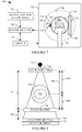
- the imaging system 700 includes a generally stationary gantry 702, which houses a rotating gantry 704 that is rotatably supported by the stationary gantry 702 and rotates around an examination region 706 about a z-axis.
- the examination region includes a field of view 716 configured for scanning a human body 715 and/or an object.
- a radiation source 708 e.g., an X-ray tube
- a radiation sensitive detector array 712 is located opposite the radiation source 108 across the examination region 706. The radiation sensitive detector array 108 detects radiation traversing the examination region 706 and generates a signal indicative thereof.
- the imaging system 700 includes an X-ray imaging interferometer having three grating structures, a source grating 714, a phase grating 718 and an analyzer grating 720.
- the source grating 714, phase grating 718 and analyzer grating 720 respectively have grating periods and are separated by distances 722 and 724 that satisfy the Talbot conditions, which are discussed in detail in Pfeiffer et al., "Hard X-ray dark-field imaging using a grating interferometer," Nature Materials 7, pp 134-137 .
- the source grating 714 is adjacent to the focal spot 710 in the path of the radiation.
- the source grating 714 creates a beam of individually coherent, but mutually incoherent sources, which traverse an object 715 in the examination region 706.
- the radiation source 708 emits a polychromatic incoherent radiation beam
- the source grating for example, an absorbing mask with transmitting slits, filters the emitted radiation beam, creating the individually coherent sources, which have sufficient spatial coherence for dark field imaging.
- the phase grating 718 is located adjacent to the object 715 and receives the refracted coherent x-rays, which result in changes of the locally transmitted intensity through the phase grating 718.
- the analyzer grating 720 is adjacent to the detector array 712 in the path of the beam. Image formation using the gratings 718 and 720 is based on the principal that a phase object placed in an X-ray beam path causes slight refraction of the beam transmitted through the object, and imaging depends on locally detecting these angular deviations. The angle can be determined based on the arrangement formed by the gratings 718 and 720.
- the gratings 718 and 720 can be considered a multi-collimator translating the angular deviations into changes of the locally transmitted intensity, which can be detected with a standard imaging detector.
- the detected intensity is a direct measure of the object's local phase gradient.
- Higher precision of the measurement can be achieved by splitting a single exposure into a set of images taken for different positions of the grating 720. This also allows the separation of the dark field signal from other contributions, such as a non-negligible absorption of the object, or an already inhomogeneous wavefront phase profile before the object.
- the object 715 causes slight refraction of coherent x-rays that is proportional to the local gradient of the real part of the refractive index of the object 715, and the angular deviation results in changes of the locally transmitted intensity through the phase grating 718 and the analyzer grating 720 that are detected by the detector array 110.
- FIGURE 8 shows a more detailed view of the source grating 714, phase grating 718 and analyzer grating 720 in connection with the focal spot 710, the object 715 and the detector array 712.
- a reconstructor 728 reconstructs the signal based on a reconstruction algorithm(s) 730, generating volumetric image data. As described in greater detail below, in one non-limiting instance, the reconstructor 728 utilizes a reconstruction algorithm that takes into account magnification of the object 715, which can be determined based on the location of the object 715 between the focal spot 710 and the phase grating 718.
- the magnification of a typical full body scanner is in a range of approximately 0.5 to 2.0. Note that although FIGURE 8 shows a single point (the middle) of the object 112 where SO and OG are determined, for reconstruction, the SO and OG can be based on the relative position of a voxel being reconstructed with respect to other voxels, and the SO and OG for two different voxel may be different.
- magnification increases with an increasing OG / decreasing SO.
- the magnification of the object if not taken into consideration, results in artifacts in the reconstructed diffusion coefficient, which degrades image quality.
- taking the magnification into account mitigates such artifacts and improves contrast, which allows for better discrimination between tissue (e.g., tumor and tissue) with similar contrast.
- taking the magnification into account mitigates blurring, resulting from the magnification, which may make it difficult to discriminate between tissue having similar contrast characteristics.
- a subject support 726 such as a couch, supports the object 715 in the examination region 706.
- a general-purpose computing system or computer serves as an operator console 732.
- the console 732 includes a human readable output device such as a monitor and an input device such as a keyboard, mouse, etc.
- Software resident on the console 732 allows the operator to interact with and/or operate the scanner 700 via a graphical user interface (GUI) or otherwise.
- GUI graphical user interface
- the reconstructor 728 can employ a reconstruction algorithm that takes magnification of the object 715 into account.
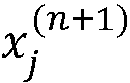
- An example reconstruction algorithm is an algebraic reconstruction technique (ART) reconstruction algorithm, which is an iterative reconstruction algorithm.
- ART algebraic reconstruction technique
- x j n + 1 is the j th voxel of the ( n +1)th image
- x j n is the j th voxel of the previous image
- b i is one the measured data (i.e., one particular line integral through the object)
- a ik is the contribution of the k th image voxel to the i th measured line integral
- a i is the sum of all a ik over k.
- the elements a ik of the so-called system matrix A contain the contribution of a voxel k to a measured line integral i as the line intersection length of the geometrical ray with the voxel. If other basis function than voxels are used, e.g., blobs, then the line integral along the ray through the basis function is used.
- the system matrix A is modified to include the magnification term M of EQUATION 6, rendering EQUATION 7:
- x j n + 1 x j n + b i ⁇ ⁇ k d ik x k n ⁇ d i ⁇ 2 d ij
- M ij is the geometrical magnification of the j -th image voxel when being projected onto the i -th detector pixel.
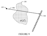
- FIGURE 9 a complementary x-ray (the x-ray of FIGURE 3 turned by 180 degrees) traverses along the path 902.
- the visibility V' is as shown in EQUATION 8:
- V ⁇ V 0 ⁇ e ⁇ ⁇ 0 L ⁇ l L ⁇ ⁇ s ⁇ ⁇ + l n ⁇ ⁇ d l , where the primes indicate that the geometrical values relate to the complementary x-ray.
- FIGURES 12 and 13 respectively show another depiction of complementary rays 1200 and 1300 over a full (or 360 degree) scan.
- EQUATION 14 represents an average of the direct measurement m (e.g., ray 1200) and the complementary measurement m' (e.g., ray 1300) and is applied to the entire 360 degree acquisition, with the resulting sinogram reconstructed using a conventional filtered back projection reconstruction algorithm.
- ⁇ represents the cosine of the fan angle.
- EQUATION 14 can be re-written, symbolically, by denoting the full original 360 degree sinogram data as D ( ⁇ , ⁇ ), where ⁇ represents an angular position of the source 710 ( FIGURE 7 ) and ⁇ represents a fan angle of a measured sample, and the sinogram of the complementary data as C ( ⁇ , ⁇ ).
- EQUATION 15 FBP F ( D ⁇ ⁇ ⁇ + C ⁇ ⁇ ⁇ ) , where ⁇ represents the linear diffusion coefficient, and F indicates fan-bean.
- the fan-beam sinograms can be rebinned to parallel beam geometry.
- EQUATIONS 15 and 16 require complementary data.
- EQUATION 18 the two FBP terms should be identical since both FBP terms operate on the entire 360 degree sinogram data with just the data being reshuffled with respect to the projection angles (with ramp-filtering and interpolation performed on the same data).
- EQUATIONS 20 and 21 allow for an extension to cone-beam geometry since no explicit averaging of the direct and complimentary rays is required.
- the conventional full scan FDK cone beam reconstruction can be applied to the weighted sinogram D' .
- An example FDK reconstruction is discussed in Feldkamp et al., "Practical cone-beam algorithm", J. Opt. Soc. Am. A/Vol. 1, No. 6/June 1984 .
- Feldkamp et al. describes the general concept, including weighting with cone-angle and 3D BP with conventional weighting.
- an aperture weighted wedge reconstruction can be applied to the weighted sinogram D', with a normalization over 2PI-partners.
- An example approach for a high-resolution aperture weighted wedge reconstruction is discussed in Shechter et al., "High-Resolution Images of Cone Beam Collimated CT Scans", IEEE Transactions on Nuclear Science 52(1), 247 (2005 ).
- Shechter et al. a wedge-rebinning (the cone-beam extension of 2D parallel rebinning) is followed by a full scan back-projection with a weighting function.
- An angular weighted wedge (or extended wedge) reconstruction can be used with an angular weighting function that ensures that the weights of all views with distance 2 ⁇ add to 1/2 independently.
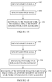
- FIGURES 10, 11 , 14 and 15 illustrate example methods. It is to be appreciated that the ordering of the acts of these methods is not limiting. As such, other orderings are contemplated herein. In addition, one or more acts may be omitted and/or one or more additional acts may be included.
- FIGURE 10 illustrates an example method.
- a dark-field signal is obtained for a scanned object.
- the dark-field signal is reconstructed using a reconstruction algorithm that includes the obtained magnification.
- FIGURE 11 illustrates another example method.
- a dark-field signal is obtained for a scanned object.
- a complementary dark-field signal is obtained for the scanned object.
- the signal and the complementary signal are 180 degrees apart.
- an average is computed based on the signal and the complementary signal.
- the average is reconstructed using a conventional filtered back-projection reconstruction algorithm.
- FIGURE 14 illustrates an example axial cone-beam CT dark field reconstruction method.
- a dark-field signal is obtained for a scanned object from a 360 degree scan.
- the dark field signal is weighted.
- a full scan FDK reconstruction algorithm is applied to the weighted dark field signal over the 360 degree scan, as described herein.
- FIGURE 15 illustrates an example helical cone-beam CT dark field reconstruction method.
- a dark-field signal is obtained for a scanned object from a 360 degree scan.
- the dark field signal is weighted.
- the weighted dark-field signal is rebinned into wedge geometry.
- an aperture or angular weighted full scan back-projection reconstruction algorithm is applied to the weighted rebinned dark field signal over the 360 degree scan, as described herein.
Landscapes
- Health & Medical Sciences (AREA)
- Life Sciences & Earth Sciences (AREA)
- Physics & Mathematics (AREA)
- General Physics & Mathematics (AREA)
- Engineering & Computer Science (AREA)
- Chemical & Material Sciences (AREA)
- Pathology (AREA)
- General Health & Medical Sciences (AREA)
- Medical Informatics (AREA)
- Crystallography & Structural Chemistry (AREA)
- Analytical Chemistry (AREA)
- Biochemistry (AREA)
- Immunology (AREA)
- Theoretical Computer Science (AREA)
- Molecular Biology (AREA)
- High Energy & Nuclear Physics (AREA)
- Nuclear Medicine, Radiotherapy & Molecular Imaging (AREA)
- Veterinary Medicine (AREA)
- Radiology & Medical Imaging (AREA)
- Biomedical Technology (AREA)
- Heart & Thoracic Surgery (AREA)
- Biophysics (AREA)
- Surgery (AREA)
- Animal Behavior & Ethology (AREA)
- Public Health (AREA)
- Optics & Photonics (AREA)
- Spectroscopy & Molecular Physics (AREA)
- Apparatus For Radiation Diagnosis (AREA)
- Algebra (AREA)
- Mathematical Analysis (AREA)
- Mathematical Optimization (AREA)
- Mathematical Physics (AREA)
- Pure & Applied Mathematics (AREA)
- Pulmonology (AREA)
Description
- The following generally relates to dark field CT imaging and more particularly to reconstructing dark field CT image data.
- In conventional CT imaging, contrast is obtained through the differences in the absorption cross-section of the constituents of the scanned object. This yields good results where highly absorbing structures such as bones are embedded in a matrix of relatively weakly absorbing material, for example the surrounding tissue of the human body. However, in cases where different forms of tissue with similar absorption cross-sections are under investigation (e.g., mammography or angiography), the X-ray absorption contrast is relatively poor. Consequently, differentiating pathologic from non-pathologic tissue in an absorption radiograph obtained with a current hospital-based X-ray system remains practically impossible for certain tissue compositions.
- Dark-field (or grating-based differential phase-contrast) imaging overcomes the above-noted contrast limitation. Generally, dark-field imaging utilizes X-ray gratings, which allow the acquisition of X-ray images in phase contrast, which provides additional information about the scanned object. With dark-field imaging, an image is generated that is based on the scatter components of the X-ray radiation diffracted by the scanned object. Very slight density differences in the scanned object then can be shown at very high resolution. Dark-field imaging is discussed in greater detail in Pfeiffer et al., "Hard X-ray dark-field imaging using a grating interferometer," Nature Materials 7, pp 134-137.
- Wang et al., "New solution for reconstruction problem about grating-based dark field computed tomography, Proc. Fully 3D 2009, 438, and Bech et al., "Quantitative x-ray dark-field computed tomography," Phys. Med. Biol. 55(2010) 5529 argue that the dark field image is a line integral of a physical quality, namely the second-moment of the small scattering distribution. Both Wang et al. and Bech et al. propose using a simple conventional filtered back-projection for reconstructing dark-field images. However, these publications are based on experiments using parallel beams and/or relatively small field of views (non-full body) and do not take into account the position of the object with respect the gratings.
- Unfortunately, simple conventional filtered back-projection (FBP) is not well-suited for fan beam geometries and larger fields of view such as those used to scan humans in hospitals for diagnostic purposes since it implicitly assumes a data acquisition model that deviates from the true acquisition as will be discussed in more detail later. This mismatch of the true acquisition and the simplified model used in standard FBP leads to artifacts (like capping or cupping). Thus, there is an unresolved need for other approaches for reconstructing dark-field image data.
- Nicholas Bevins, Joseph Zambelli, Zhihua Qi, Guang-Hong Chen, "X-ray dark-field computed tomography using a grating interferometer setup", Proc. SPIE 7622, Medical Imaging 2010: Physics of Medical Imaging, 76220P (March 18, 2010), discloses that a dark-field x-ray imaging method is extended to x-ray computed tomography in order to provide unique and complementary information to phase contrast and absorption contrast CT images. Dark-field reconstructions are presented and compared to these two other contrast mechanisms, all three of which can be obtained from a single acquisition using an x-ray grating interferometer setup.
- Aspects described herein address the above-referenced problems and others.
- In one aspect, the invention provides a method according to claim 1.
- In another aspect, the invention provides an imaging system according to claim 11.
In another aspect, the invention provides a computer readable storage medium according to claim 15. - The invention may take form in various components and arrangements of components, and in various steps and arrangements of steps. The drawings are only for purposes of illustrating the preferred embodiments and are not to be construed as limiting the invention.
-
FIGURES 1-3 schematically illustrates attenuation and magnification for attenuation contrast imaging. -
FIGURE 4-6 schematically illustrates attenuation and magnification for dark field imaging. -
FIGURES 7 and 8 schematically illustrate an example imaging system with an interferometer for dark-field imaging. -
FIGURE 9 schematically illustrates attenuation for a ray complementary to the ray ofFIGURE 6 . -
FIGURE 10 illustrates an example method for reconstructing a dark field signal with a reconstruction algorithm that includes an inverse signal magnification of the scanned object. -
FIGURE 11 illustrates an example method for reconstructing an average dark field signal with a filtered back projection reconstruction algorithm. -
FIGURES 12 and 13 respectively show another depiction of complementary rays over a full (or 360 degree) scan. -
FIGURE 14 illustrates an example axial cone-beam CT dark field reconstruction method. -
FIGURE 15 illustrates an example helical cone-beam CT dark field reconstruction method. - Conventional dark-field imaging reconstruction algorithms do not take into account "inverse signal magnification." Generally, "inverse signal magnification" is a magnification that scales the height of the detected signal inversely with respect to the position of an object between the source of radiation and the detector. That is, the height of the detector signal for an object closer to the radiation source will be smaller (
FIGURE 4 , 402) than the height of the detector signal for the object positioned farther from the source (FIGURE 5 , 500). - "Inverse signal magnification" does not affect attenuation contrast imaging (
FIGURES 1 and 2 , 110 and 200), but it introduces artifact (e.g., blurring) into dark-field images, which may make it difficult to discriminate between tissue having similar contrast characteristics. The following describes an approach(s) for taking the "inverse signal magnification" into account with dark-field imaging by including a magnification term in the reconstruction algorithm or a reconstruction formulation which cancels the magnification from the reconstruction, thus, mitigating the artifacts introduced into dark field images thereby. - Turning to
FIGURES 1-6 , conventional filtered back-projection is not well-suited for dark-field signal reconstruction with larger fields of view such as those used to scan humans. This is discussed is greater detail next in connection withFIGURES 1-6 . - With attenuation contrast imaging , as shown in
FIGURES 1-2 , depending on a position of anobject 100 between asource 102 and adetector array 104, the respective measuredprojections signal heights 110 and 202 (i.e. values of line integrals) are the same. - With attenuation contrast imaging, as shown in
FIGURE 3 , an x-ray traverses along apath 302 from thesource 102, through theobject 100, to adetector pixel 304 of thedetector array 104. The attenuation of the x-ray along thepath 302 occurs exponentially, as shown in EQUATION 1:
source 102 through theobject 100 to the detector pixel 306, µ is the attenuation coefficient,s is the source position, and n is a unit vector along the x-ray. Logging both sides of the equations renders a linear equation representing the line integral of the attenuation coefficient along thepath 302, as shown in EQUATION 2:
- With dark field imaging, as shown in
FIGURES 4 and 5 , depending on the position of theobject 100 between thesource 102 and thedetector array 104, the respective measuredprojections signal heights 402 and 502 (i.e. values of line integrals) scale inversely with "inverse signal magnification." - As shown in
FIGURE 6 , for dark field imaging, the loss of visibility of the x-ray along thepath 302 is as shown in EQUATION 3:
path 302 in analogy to the attenuation coefficient but rather to a weighted line integral as shown in EQUATION 4:
- Similar to attenuation contrast imaging, the "size magnification" is taken into account in conventional fan-beam FBP algorithms; howerver, the "inverse signal magnification" (1/L) is not taken into account in conventional fan-beam FBP algorithms. The additional weighting l/L. does not permit to use a conventional filtered back-projection to reconstruct the distribution of the diffusion coefficient. If the weighting factor barely changes over the object's extend, for example if the object is very small compared to the distance L, the additional weighting can be approximated to be constant or dropped.
- Turning to
FIGURE 7 , animaging system 700 such as a CT scanner is schematically illustrated. The CT scanner can be a full body, head, or small bore scanner. Theimaging system 700 includes a generallystationary gantry 702, which houses a rotatinggantry 704 that is rotatably supported by thestationary gantry 702 and rotates around anexamination region 706 about a z-axis. The examination region includes a field ofview 716 configured for scanning ahuman body 715 and/or an object. - A radiation source 708 (e.g., an X-ray tube) with a
focal spot 710 is rotatably supported by the rotatinggantry 704, rotates with the rotatinggantry 704, and emits radiation. A radiationsensitive detector array 712 is located opposite the radiation source 108 across theexamination region 706. The radiation sensitive detector array 108 detects radiation traversing theexamination region 706 and generates a signal indicative thereof. - The
imaging system 700 includes an X-ray imaging interferometer having three grating structures, a source grating 714, aphase grating 718 and ananalyzer grating 720. The source grating 714, phase grating 718 andanalyzer grating 720 respectively have grating periods and are separated bydistances - The source grating 714 is adjacent to the
focal spot 710 in the path of the radiation. The source grating 714 creates a beam of individually coherent, but mutually incoherent sources, which traverse anobject 715 in theexamination region 706. Generally, theradiation source 708 emits a polychromatic incoherent radiation beam, and the source grating, for example, an absorbing mask with transmitting slits, filters the emitted radiation beam, creating the individually coherent sources, which have sufficient spatial coherence for dark field imaging. - The phase grating 718 is located adjacent to the
object 715 and receives the refracted coherent x-rays, which result in changes of the locally transmitted intensity through the phase grating 718. Theanalyzer grating 720 is adjacent to thedetector array 712 in the path of the beam. Image formation using thegratings gratings - The
gratings grating 720. This also allows the separation of the dark field signal from other contributions, such as a non-negligible absorption of the object, or an already inhomogeneous wavefront phase profile before the object. - Generally, the
object 715 causes slight refraction of coherent x-rays that is proportional to the local gradient of the real part of the refractive index of theobject 715, and the angular deviation results in changes of the locally transmitted intensity through the phase grating 718 and the analyzer grating 720 that are detected by thedetector array 110.FIGURE 8 shows a more detailed view of the source grating 714, phase grating 718 and analyzer grating 720 in connection with thefocal spot 710, theobject 715 and thedetector array 712. - A
reconstructor 728 reconstructs the signal based on a reconstruction algorithm(s) 730, generating volumetric image data. As described in greater detail below, in one non-limiting instance, thereconstructor 728 utilizes a reconstruction algorithm that takes into account magnification of theobject 715, which can be determined based on the location of theobject 715 between thefocal spot 710 and the phase grating 718. - The magnification can be estimated based on EQUATION 5:

object distance 802, OG represents an object-to-phasegrating distance 804, and SO + OG represents a source grating-to-phase grating (SG)distance 806. The magnification of a typical full body scanner is in a range of approximately 0.5 to 2.0. Note that althoughFIGURE 8 shows a single point (the middle) of the object 112 where SO and OG are determined, for reconstruction, the SO and OG can be based on the relative position of a voxel being reconstructed with respect to other voxels, and the SO and OG for two different voxel may be different. - From EQUATION 5, the magnification increases with an increasing OG / decreasing SO. Unfortunately, the magnification of the object, if not taken into consideration, results in artifacts in the reconstructed diffusion coefficient, which degrades image quality. As described in detail bellow, taking the magnification into account mitigates such artifacts and improves contrast, which allows for better discrimination between tissue (e.g., tumor and tissue) with similar contrast. For example, taking the magnification into account mitigates blurring, resulting from the magnification, which may make it difficult to discriminate between tissue having similar contrast characteristics.
- A
subject support 726, such as a couch, supports theobject 715 in theexamination region 706. A general-purpose computing system or computer serves as anoperator console 732. Theconsole 732 includes a human readable output device such as a monitor and an input device such as a keyboard, mouse, etc. Software resident on theconsole 732 allows the operator to interact with and/or operate thescanner 700 via a graphical user interface (GUI) or otherwise. - As discussed above, the
reconstructor 728 can employ a reconstruction algorithm that takes magnification of theobject 715 into account. An example reconstruction algorithm is an algebraic reconstruction technique (ART) reconstruction algorithm, which is an iterative reconstruction algorithm. For a conventional attenuation contrast CT reconstruction, a suitable ART is shown in EQUATION 6:

- To take into account magnification, the system matrix A is modified to include the magnification term M of EQUATION 6, rendering EQUATION 7:

- The following describes another suitable reconstruction. In
FIGURE 9 , a complementary x-ray (the x-ray ofFIGURE 3 turned by 180 degrees) traverses along thepath 902. The visibility V' is as shown in EQUATION 8:
complementary path 902, as shown in EQUATION 9:
- In Equation 9, the fact that by definition of the complementary ray, the relation
n ' = -n holds true is exploited. Furthermore, it is assumed, for the sake of simplicity, L=L'. The source position for the complementary x-ray is somewhere on the ray ofFIGURE 3 :s ' =s + λn for some λ. Substituting this into EQUATION 9 renders EQUATION 10:
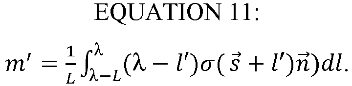


- For an axial 2D full scan, a weighted average for the ray 300 and the complementary ray can be computed as shown in EQUATION 14:

- EQUATION 14 requires acquisition of the complementary ray and, thus, EQUATION 14 cannot be used for cone-beam reconstruction. The following describes an approach that extends EQUATION 14 for cone beam reconstruction.
FIGURES 12 and 13 respectively show another depiction ofcomplementary rays - Again, EQUATION 14 represents an average of the direct measurement m (e.g., ray 1200) and the complementary measurement m' (e.g., ray 1300) and is applied to the entire 360 degree acquisition, with the resulting sinogram reconstructed using a conventional filtered back projection reconstruction algorithm. In EQUATION 14, λ represents the cosine of the fan angle.
- EQUATION 14 can be re-written, symbolically, by denoting the full original 360 degree sinogram data as D(α,φ), where α represents an angular position of the source 710 (
FIGURE 7 ) and φ represents a fan angle of a measured sample, and the sinogram of the complementary data as C(α,φ). The relationship between complementary data and direct data is C(α,φ) = D(α+π-2φ,-φ). Weighted complementary and weighted direct data are respectively represented as D'(α,φ) = (1/cos(φ))D(α,φ) and C'(α,φ) = (1/cos(φ))C(α,φ). - From this, the original, exact FBP reconstruction can be written as shown in EQUATION 15:


- Leveraging the linearity of FBP, EQUATION 16 can be expressed as shown in EQUATION 17:

complementary ray 1300 is also a direct ray (just 180 degrees or π apart from the direct ray 1200), EQUATION 17 can be expressed as EQUATION 18:
- In EQUATION 18, the two FBP terms should be identical since both FBP terms operate on the entire 360 degree sinogram data with just the data being reshuffled with respect to the projection angles (with ramp-filtering and interpolation performed on the same data). As such, EQUATION 17 can be written as EQUATIONS 19 and 20, using D'(r;β) as an approximation for C'(r,β):


- Rebinning the parallel-beam data back into the original fan-beam geometry renders EQUATION 21:

- EQUATIONS 20 and 21 allow for an extension to cone-beam geometry since no explicit averaging of the direct and complimentary rays is required. For example, for a 360 degree axial cone-beam CT scan, the conventional full scan FDK cone beam reconstruction can be applied to the weighted sinogram D'. An example FDK reconstruction is discussed in Feldkamp et al., "Practical cone-beam algorithm", J. Opt. Soc. Am. A/Vol. 1, No. 6/June 1984. Feldkamp et al. describes the general concept, including weighting with cone-angle and 3D BP with conventional weighting.
- For a helical cone-beam CT scan, an aperture weighted wedge reconstruction can be applied to the weighted sinogram D', with a normalization over 2PI-partners. An example approach for a high-resolution aperture weighted wedge reconstruction is discussed in Shechter et al., "High-Resolution Images of Cone Beam Collimated CT Scans", IEEE Transactions on Nuclear Science 52(1), 247 (2005). In Shechter et al., a wedge-rebinning (the cone-beam extension of 2D parallel rebinning) is followed by a full scan back-projection with a weighting function. An angular weighted wedge (or extended wedge) reconstruction can be used with an angular weighting function that ensures that the weights of all views with distance 2π add to 1/2 independently.
-
FIGURES 10, 11 ,14 and 15 illustrate example methods. It is to be appreciated that the ordering of the acts of these methods is not limiting. As such, other orderings are contemplated herein. In addition, one or more acts may be omitted and/or one or more additional acts may be included. -
FIGURE 10 illustrates an example method. - At 1002, a dark-field signal is obtained for a scanned object.
- At 1004, an inverse signal magnification of the scanned object is obtained.
- At 1006, the dark-field signal is reconstructed using a reconstruction algorithm that includes the obtained magnification.
-
FIGURE 11 illustrates another example method. - At 1102, a dark-field signal is obtained for a scanned object.
- At 1104, a complementary dark-field signal is obtained for the scanned object. The signal and the complementary signal are 180 degrees apart.
- At 1106, an average is computed based on the signal and the complementary signal.
- At 1108, the average is reconstructed using a conventional filtered back-projection reconstruction algorithm.
-
FIGURE 14 illustrates an example axial cone-beam CT dark field reconstruction method. - At 1402, a dark-field signal is obtained for a scanned object from a 360 degree scan.
- At 1404, the dark field signal is weighted.
- At 1406, a full scan FDK reconstruction algorithm is applied to the weighted dark field signal over the 360 degree scan, as described herein.
-
FIGURE 15 illustrates an example helical cone-beam CT dark field reconstruction method. - At 1502, a dark-field signal is obtained for a scanned object from a 360 degree scan.
- At 1504, the dark field signal is weighted.
- At 1506, the weighted dark-field signal is rebinned into wedge geometry.
- At 1508, an aperture or angular weighted full scan back-projection reconstruction algorithm is applied to the weighted rebinned dark field signal over the 360 degree scan, as described herein.
- The invention has been described with reference to the preferred embodiments. Modifications and alterations may occur to others upon reading and understanding the preceding detailed description. It is intended that the invention be construed as including all such modifications and alterations insofar as they come within the scope of the appended claims or the equivalents thereof.
Claims (15)
- A method, comprising:obtaining a dark-field signal generated from a dark-field CT scan of an object using a detector array that detects radiation emitted from a focal spot and traversing the examination region,wherein the dark-field CT scan is at least a 360 degree scan;weighting the dark-field signal; andperforming a cone beam reconstruction of the weighted dark-field signal over the 360 degree scan, thereby generating volumetric image data.wherein the weighting is based on the fan angle of the dark-field signal.
- The method of claim 1, wherein the cone beam reconstruction does not require a complementary dark-field signal for the scanned object, which is a signal acquired one hundred and eighty degrees apart from the dark-field signal.
- The method of any of claims 1 to 2, wherein the cone beam reconstruction is an extension of a 2D filtered back-projection reconstruction over the 360 degree scan.
- The method of claim 3, wherein the 2D filtered back-projection reconstruction includes a term that is a function of the complementary dark-field signal, and further comprising:approximating the complementary dark-field signal in the term with the dark-field signal.
- The method of any of claims 3 to 4, wherein the 2D filtered back-projection reconstruction includes applying a filtered back-projection to the weighted dark-field signal and multiplying a result of the filtered back-projection by a value of two.
- The method of any of claims 1 to 5, wherein the dark-field CT scan is an axial cone-beam CT scan, and the cone-beam reconstruction is a 360 degree FDK cone beam reconstruction.
- The method of any of claims 1 to 5, wherein the dark-field CT scan is a helical cone-beam CT scan.
- The method of claim 7, further comprising:rebinning the dark-field signal to a wedge geometry, and wherein the cone-beam reconstruction is an aperture weighted wedge reconstruction.
- The method of claim 7, further comprising:rebinning the dark-field signal to a wedge geometry, and wherein the cone-beam reconstruction is an angular weighted wedge reconstruction.
- The method of any claim 9, wherein the weights of all views with distance 2□ add to 1/2 independently.
- An imaging system (700), comprising:a focal spot (710) that emits radiation that traverses an examination region;an interferometer (714, 718, 720) that filters the emitted radiation for a dark-field imaging scan of an object; anda detector array (712) that detects the filtered radiation traversing the examination region and produces a dark-field signal indicative thereof; anda reconstructor (728) that weights the dark-field signal and reconstructs the weighted dark-field signal over 360 degrees using a cone beam reconstruction, generating volumetric image data.wherein the weighting is based on the fan angle of the dark-field signal.
- The imaging system of claim 11, wherein the cone beam reconstruction does not require a complementary dark-field signal for the scanned object, which is a signal acquired one hundred and eighty degrees apart from the dark-field signal.
- The imaging system of any of claims 11 to 12, wherein the reconstructor applies a cone beam reconstruction that is an extension of a 2D filtered back-projection reconstruction over the 360 degrees.
- The imaging system of claim 13, wherein the 2D filtered back-projection reconstruction includes a term that is a function of the complementary dark-field signal, which approximated with the dark-field signal.
- A computer readable storage medium encoded with computer readable instructions, which, when executed by a processer, cause the processor to:obtain a dark-field signal generated from at least a 360 degree dark-field CT scan of an object using a detector array that detects radiation emitted from a focal spot and traversing the examination region;weight the dark-field signal; andperform a cone beam reconstruction on the weighted dark-field signal over 360 degrees, thereby generating volumetric image data. wherein the weighting is based on the fan angle of the dark-field signal.
Applications Claiming Priority (2)
| Application Number | Priority Date | Filing Date | Title |
|---|---|---|---|
| US201261646520P | 2012-05-14 | 2012-05-14 | |
| PCT/IB2013/053881 WO2013171657A1 (en) | 2012-05-14 | 2013-05-13 | Dark field computed tomography imaging |
Publications (2)
| Publication Number | Publication Date |
|---|---|
| EP2850595A1 EP2850595A1 (en) | 2015-03-25 |
| EP2850595B1 true EP2850595B1 (en) | 2016-04-06 |
Family
ID=48703619
Family Applications (1)
| Application Number | Title | Priority Date | Filing Date |
|---|---|---|---|
| EP13732626.0A Not-in-force EP2850595B1 (en) | 2012-05-14 | 2013-05-13 | Dark field computed tomography imaging |
Country Status (4)
| Country | Link |
|---|---|
| US (1) | US9761021B2 (en) |
| EP (1) | EP2850595B1 (en) |
| CN (1) | CN104321805B (en) |
| WO (1) | WO2013171657A1 (en) |
Families Citing this family (48)
| Publication number | Priority date | Publication date | Assignee | Title |
|---|---|---|---|---|
| US20150117599A1 (en) * | 2013-10-31 | 2015-04-30 | Sigray, Inc. | X-ray interferometric imaging system |
| WO2014002026A1 (en) | 2012-06-27 | 2014-01-03 | Koninklijke Philips N.V. | Dark-field imaging |
| US10295485B2 (en) | 2013-12-05 | 2019-05-21 | Sigray, Inc. | X-ray transmission spectrometer system |
| USRE48612E1 (en) | 2013-10-31 | 2021-06-29 | Sigray, Inc. | X-ray interferometric imaging system |
| US10401309B2 (en) | 2014-05-15 | 2019-09-03 | Sigray, Inc. | X-ray techniques using structured illumination |
| CN106575533B (en) * | 2014-08-05 | 2018-11-27 | 皇家飞利浦有限公司 | Gating devices for x-ray imaging equipment |
| CN106659449B (en) | 2014-08-13 | 2020-11-24 | 皇家飞利浦有限公司 | Quantitative Darkfield Imaging in Tomography |
| EP3134000B1 (en) * | 2015-05-06 | 2017-10-25 | Koninklijke Philips N.V. | Optimal energy weighting of dark field signal in differential phase contrast x-ray imaging |
| JP6805173B2 (en) * | 2015-05-07 | 2020-12-23 | コーニンクレッカ フィリップス エヌ ヴェKoninklijke Philips N.V. | Beam hardening correction for scanning darkfield / phase contrast imaging |
| JP6816144B2 (en) * | 2015-12-01 | 2021-01-20 | コーニンクレッカ フィリップス エヌ ヴェKoninklijke Philips N.V. | A device for X-ray imaging of a subject |
| US11266363B2 (en) * | 2016-02-17 | 2022-03-08 | Rensselaer Polytechnic Institute | Energy-sensitive multi-contrast cost-effective CT system |
| CN106228601B (en) * | 2016-07-21 | 2019-08-06 | 山东大学 | Fast 3D Reconstruction Method of Multiscale Cone Beam CT Images Based on Wavelet Transform |
| CN109688930A (en) | 2016-09-08 | 2019-04-26 | 皇家飞利浦有限公司 | Source grating for x-ray imaging |
| EP3510563B1 (en) * | 2016-09-08 | 2021-11-10 | Koninklijke Philips N.V. | Improved phase-contrast and dark-field ct reconstruction algorithm |
| US10247683B2 (en) | 2016-12-03 | 2019-04-02 | Sigray, Inc. | Material measurement techniques using multiple X-ray micro-beams |
| US11026643B2 (en) | 2016-12-06 | 2021-06-08 | Koninklijke Philips N.V. | Interferometer grating support for grating-based x-ray imaging and/or a support bracket therefor |
| WO2018175570A1 (en) | 2017-03-22 | 2018-09-27 | Sigray, Inc. | Method of performing x-ray spectroscopy and x-ray absorption spectrometer system |
| CN107238616B (en) * | 2017-06-22 | 2019-10-11 | 合肥工业大学 | Dark field imaging method based on neutron grating interferometer |
| US11382574B2 (en) | 2017-11-06 | 2022-07-12 | Rensselaer Polytechnic Institute | Stationary in-vivo grating-enabled micro-CT architecture (sigma) |
| JP6962658B2 (en) * | 2018-01-17 | 2021-11-05 | ダイハツ工業株式会社 | Visual inspection equipment |
| CN108720863B (en) * | 2018-02-12 | 2021-06-01 | 沈阳晟诺科技有限公司 | Focus switching type CT machine, scanning method and image reconstruction method |
| CN108283503B (en) * | 2018-02-12 | 2021-08-20 | 沈阳晟诺科技有限公司 | CT machine, scanning method and image reconstruction method |
| US10578566B2 (en) | 2018-04-03 | 2020-03-03 | Sigray, Inc. | X-ray emission spectrometer system |
| CN112424591B (en) | 2018-06-04 | 2024-05-24 | 斯格瑞公司 | Wavelength dispersive X-ray spectrometer |
| DE112019003777B4 (en) | 2018-07-26 | 2025-09-11 | Sigray, Inc. | HIGH BRIGHTNESS X-RAY REFLECTION SOURCE |
| US10656105B2 (en) | 2018-08-06 | 2020-05-19 | Sigray, Inc. | Talbot-lau x-ray source and interferometric system |
| CN112638261B (en) | 2018-09-04 | 2025-06-27 | 斯格瑞公司 | Systems and methods utilizing filtered x-ray fluorescence |
| US11056308B2 (en) | 2018-09-07 | 2021-07-06 | Sigray, Inc. | System and method for depth-selectable x-ray analysis |
| US11006912B2 (en) * | 2019-03-25 | 2021-05-18 | Battelle Memorial Institute | Methods, systems, and computer-readable storage media for enhanced phase-contrast x-ray imaging |
| US11639903B2 (en) | 2019-03-25 | 2023-05-02 | Battelle Memorial Institute | Serial Moire scanning phase contrast x-ray imaging |
| JP7182749B2 (en) | 2019-09-03 | 2022-12-02 | シグレイ、インコーポレイテッド | System and method for computed tomography fluorescence X-ray imaging |
| US11175243B1 (en) | 2020-02-06 | 2021-11-16 | Sigray, Inc. | X-ray dark-field in-line inspection for semiconductor samples |
| WO2021237237A1 (en) | 2020-05-18 | 2021-11-25 | Sigray, Inc. | System and method for x-ray absorption spectroscopy using a crystal analyzer and a plurality of detector elements |
| EP3940647A1 (en) | 2020-07-14 | 2022-01-19 | Koninklijke Philips N.V. | Deep learning for sliding window phase retrieval |
| WO2022061347A1 (en) | 2020-09-17 | 2022-03-24 | Sigray, Inc. | System and method using x-rays for depth-resolving metrology and analysis |
| KR20260030946A (en) | 2020-12-07 | 2026-03-06 | 시그레이, 아이엔씨. | High throughput 3d x-ray imaging system using a transmission x-ray source |
| US12480892B2 (en) | 2020-12-07 | 2025-11-25 | Sigray, Inc. | High throughput 3D x-ray imaging system using a transmission x-ray source |
| CN113240766B (en) * | 2021-05-28 | 2023-08-18 | 有方(合肥)医疗科技有限公司 | Geometric Parameter Acquisition Method and Acquisition System of Cone Beam CT System |
| EP4152266A1 (en) | 2021-09-16 | 2023-03-22 | Koninklijke Philips N.V. | Dark-field and phase-contrast tomography reconstruction algorithm |
| WO2023168204A1 (en) | 2022-03-02 | 2023-09-07 | Sigray, Inc. | X-ray fluorescence system and x-ray source with electrically insulative target material |
| US11992350B2 (en) | 2022-03-15 | 2024-05-28 | Sigray, Inc. | System and method for compact laminography utilizing microfocus transmission x-ray source and variable magnification x-ray detector |
| WO2023215204A1 (en) | 2022-05-02 | 2023-11-09 | Sigray, Inc. | X-ray sequential array wavelength dispersive spectrometer |
| DE112024000873T5 (en) | 2023-02-16 | 2026-01-15 | Sigray, Inc. | X-ray detector system with at least two stacked flat Bragg diffractors |
| US12181423B1 (en) | 2023-09-07 | 2024-12-31 | Sigray, Inc. | Secondary image removal using high resolution x-ray transmission sources |
| US12429437B2 (en) | 2023-11-07 | 2025-09-30 | Sigray, Inc. | System and method for x-ray absorption spectroscopy using spectral information from two orthogonal planes |
| WO2025151383A1 (en) | 2024-01-08 | 2025-07-17 | Sigray, Inc. | X-ray analysis system with focused x-ray beam and non-x-ray microscope |
| WO2025155719A1 (en) | 2024-01-18 | 2025-07-24 | Sigray, Inc. | Sequential array of x-ray imaging detectors |
| WO2025174966A1 (en) | 2024-02-15 | 2025-08-21 | Sigray, Inc. | System and method for generating a focused x‑ray beam |
Family Cites Families (6)
| Publication number | Priority date | Publication date | Assignee | Title |
|---|---|---|---|---|
| EP1576355A2 (en) * | 2002-09-30 | 2005-09-21 | Applied Materials Israel Ltd. | Illumination system for optical inspection |
| CN201191275Y (en) * | 2007-11-23 | 2009-02-04 | 同方威视技术股份有限公司 | An X-ray Grating Phase Contrast Imaging System |
| WO2010141839A2 (en) * | 2009-06-04 | 2010-12-09 | Virginia Tech Intellectual Properties, Inc. | Multi-parameter x-ray computed tomography |
| CN101943668B (en) * | 2009-07-07 | 2013-03-27 | 清华大学 | X-ray dark-field imaging system and method |
| CN102221565B (en) | 2010-04-19 | 2013-06-12 | 清华大学 | X-ray source grating stepping imaging system and imaging method |
| WO2012000694A1 (en) | 2010-06-28 | 2012-01-05 | Paul Scherrer Institut | A method for x-ray phase contrast and dark-field imaging using an arrangement of gratings in planar geometry |
-
2013
- 2013-05-13 US US14/397,878 patent/US9761021B2/en not_active Expired - Fee Related
- 2013-05-13 EP EP13732626.0A patent/EP2850595B1/en not_active Not-in-force
- 2013-05-13 WO PCT/IB2013/053881 patent/WO2013171657A1/en not_active Ceased
- 2013-05-13 CN CN201380025354.5A patent/CN104321805B/en not_active Expired - Fee Related
Also Published As
| Publication number | Publication date |
|---|---|
| WO2013171657A1 (en) | 2013-11-21 |
| US20150124927A1 (en) | 2015-05-07 |
| US9761021B2 (en) | 2017-09-12 |
| CN104321805B (en) | 2017-12-15 |
| CN104321805A (en) | 2015-01-28 |
| EP2850595A1 (en) | 2015-03-25 |
Similar Documents
| Publication | Publication Date | Title |
|---|---|---|
| US9761021B2 (en) | Dark field computed tomography imaging | |
| US10779789B2 (en) | Empirical beam hardening correction for differential phase contrast CT | |
| Sera | Computed tomography | |
| US20100119033A1 (en) | Intensity-modulated, cone-beam computed tomographic imaging system, methods, and apparatus | |
| EP3180603B1 (en) | Quantitative dark field imaging in tomography | |
| Tang et al. | Characterization of imaging performance in differential phase contrast ct compared with the conventional ct: Spectrum of noise equivalent quanta neq (k) | |
| JP2017209498A (en) | X-ray computer tomography apparatus and medical image processor | |
| CN103339497B (en) | Probe value treatment facility | |
| Hernandez et al. | Effects of kV, filtration, dose, and object size on soft tissue and iodine contrast in dedicated breast CT | |
| Fu et al. | Helical differential X-ray phase-contrast computed tomography | |
| JP2023039438A (en) | Image generation device, x-ray ct apparatus and image generation method | |
| Chen et al. | Image reconstruction for fan-beam differential phase contrast computed tomography | |
| Xu et al. | Intensity-based iterative reconstruction for helical grating interferometry breast CT with static grating configuration | |
| van Stevendaal et al. | Reconstruction method incorporating the object-position dependence of visibility loss in dark-field imaging | |
| Cho et al. | Region‐of‐interest image reconstruction in circular cone‐beam microCT | |
| Li et al. | Estimation of signal and noise for a whole-body research photon-counting CT system | |
| Guo et al. | Analytical Reconstruction of Human-Scale Dark-Field CT | |
| Takane et al. | Accuracy of virtual non-contrast images with different algorithms in dual-energy computed tomography | |
| CN101331516A (en) | Advanced convergence for multiple iteration algorithms | |
| Qi et al. | A local region of interest image reconstruction via filtered backprojection for fan-beam differential phase-contrast computed tomography | |
| Zhang et al. | Performance evaluation of dual‐energy CT and differential phase contrast CT in quantitative imaging applications | |
| Cai et al. | Dose efficiency consideration for volume-of-interest breast imaging using x-ray differential phase-contrast CT | |
| Ghammraoui et al. | Influence of phantom design on evaluation metrics in photon counting spectral head CT: a simulation study | |
| Haidekker | Computed tomography | |
| JP2008519634A (en) | Energy-resolved computer tomography |
Legal Events
| Date | Code | Title | Description |
|---|---|---|---|
| PUAI | Public reference made under article 153(3) epc to a published international application that has entered the european phase |
Free format text: ORIGINAL CODE: 0009012 |
|
| 17P | Request for examination filed |
Effective date: 20141215 |
|
| AK | Designated contracting states |
Kind code of ref document: A1 Designated state(s): AL AT BE BG CH CY CZ DE DK EE ES FI FR GB GR HR HU IE IS IT LI LT LU LV MC MK MT NL NO PL PT RO RS SE SI SK SM TR |
|
| AX | Request for extension of the european patent |
Extension state: BA ME |
|
| DAX | Request for extension of the european patent (deleted) | ||
| GRAP | Despatch of communication of intention to grant a patent |
Free format text: ORIGINAL CODE: EPIDOSNIGR1 |
|
| INTG | Intention to grant announced |
Effective date: 20151005 |
|
| GRAS | Grant fee paid |
Free format text: ORIGINAL CODE: EPIDOSNIGR3 |
|
| GRAA | (expected) grant |
Free format text: ORIGINAL CODE: 0009210 |
|
| AK | Designated contracting states |
Kind code of ref document: B1 Designated state(s): AL AT BE BG CH CY CZ DE DK EE ES FI FR GB GR HR HU IE IS IT LI LT LU LV MC MK MT NL NO PL PT RO RS SE SI SK SM TR |
|
| REG | Reference to a national code |
Ref country code: GB Ref legal event code: FG4D |
|
| REG | Reference to a national code |
Ref country code: AT Ref legal event code: REF Ref document number: 788518 Country of ref document: AT Kind code of ref document: T Effective date: 20160415 Ref country code: CH Ref legal event code: EP |
|
| REG | Reference to a national code |
Ref country code: IE Ref legal event code: FG4D |
|
| REG | Reference to a national code |
Ref country code: DE Ref legal event code: R096 Ref document number: 602013006341 Country of ref document: DE |
|
| REG | Reference to a national code |
Ref country code: FR Ref legal event code: PLFP Year of fee payment: 4 |
|
| REG | Reference to a national code |
Ref country code: DE Ref legal event code: R084 Ref document number: 602013006341 Country of ref document: DE |
|
| REG | Reference to a national code |
Ref country code: LT Ref legal event code: MG4D Ref country code: NL Ref legal event code: MP Effective date: 20160406 |
|
| REG | Reference to a national code |
Ref country code: AT Ref legal event code: MK05 Ref document number: 788518 Country of ref document: AT Kind code of ref document: T Effective date: 20160406 |
|
| PG25 | Lapsed in a contracting state [announced via postgrant information from national office to epo] |
Ref country code: BE Free format text: LAPSE BECAUSE OF NON-PAYMENT OF DUE FEES Effective date: 20160531 |
|
| PG25 | Lapsed in a contracting state [announced via postgrant information from national office to epo] |
Ref country code: NL Free format text: LAPSE BECAUSE OF FAILURE TO SUBMIT A TRANSLATION OF THE DESCRIPTION OR TO PAY THE FEE WITHIN THE PRESCRIBED TIME-LIMIT Effective date: 20160406 |
|
| PG25 | Lapsed in a contracting state [announced via postgrant information from national office to epo] |
Ref country code: IS Free format text: LAPSE BECAUSE OF FAILURE TO SUBMIT A TRANSLATION OF THE DESCRIPTION OR TO PAY THE FEE WITHIN THE PRESCRIBED TIME-LIMIT Effective date: 20160806 Ref country code: PL Free format text: LAPSE BECAUSE OF FAILURE TO SUBMIT A TRANSLATION OF THE DESCRIPTION OR TO PAY THE FEE WITHIN THE PRESCRIBED TIME-LIMIT Effective date: 20160406 Ref country code: LT Free format text: LAPSE BECAUSE OF FAILURE TO SUBMIT A TRANSLATION OF THE DESCRIPTION OR TO PAY THE FEE WITHIN THE PRESCRIBED TIME-LIMIT Effective date: 20160406 Ref country code: FI Free format text: LAPSE BECAUSE OF FAILURE TO SUBMIT A TRANSLATION OF THE DESCRIPTION OR TO PAY THE FEE WITHIN THE PRESCRIBED TIME-LIMIT Effective date: 20160406 Ref country code: NO Free format text: LAPSE BECAUSE OF FAILURE TO SUBMIT A TRANSLATION OF THE DESCRIPTION OR TO PAY THE FEE WITHIN THE PRESCRIBED TIME-LIMIT Effective date: 20160706 |
|
| PG25 | Lapsed in a contracting state [announced via postgrant information from national office to epo] |
Ref country code: AT Free format text: LAPSE BECAUSE OF FAILURE TO SUBMIT A TRANSLATION OF THE DESCRIPTION OR TO PAY THE FEE WITHIN THE PRESCRIBED TIME-LIMIT Effective date: 20160406 Ref country code: SE Free format text: LAPSE BECAUSE OF FAILURE TO SUBMIT A TRANSLATION OF THE DESCRIPTION OR TO PAY THE FEE WITHIN THE PRESCRIBED TIME-LIMIT Effective date: 20160406 Ref country code: GR Free format text: LAPSE BECAUSE OF FAILURE TO SUBMIT A TRANSLATION OF THE DESCRIPTION OR TO PAY THE FEE WITHIN THE PRESCRIBED TIME-LIMIT Effective date: 20160707 Ref country code: RS Free format text: LAPSE BECAUSE OF FAILURE TO SUBMIT A TRANSLATION OF THE DESCRIPTION OR TO PAY THE FEE WITHIN THE PRESCRIBED TIME-LIMIT Effective date: 20160406 Ref country code: HR Free format text: LAPSE BECAUSE OF FAILURE TO SUBMIT A TRANSLATION OF THE DESCRIPTION OR TO PAY THE FEE WITHIN THE PRESCRIBED TIME-LIMIT Effective date: 20160406 Ref country code: ES Free format text: LAPSE BECAUSE OF FAILURE TO SUBMIT A TRANSLATION OF THE DESCRIPTION OR TO PAY THE FEE WITHIN THE PRESCRIBED TIME-LIMIT Effective date: 20160406 Ref country code: PT Free format text: LAPSE BECAUSE OF FAILURE TO SUBMIT A TRANSLATION OF THE DESCRIPTION OR TO PAY THE FEE WITHIN THE PRESCRIBED TIME-LIMIT Effective date: 20160808 Ref country code: LV Free format text: LAPSE BECAUSE OF FAILURE TO SUBMIT A TRANSLATION OF THE DESCRIPTION OR TO PAY THE FEE WITHIN THE PRESCRIBED TIME-LIMIT Effective date: 20160406 |
|
| PG25 | Lapsed in a contracting state [announced via postgrant information from national office to epo] |
Ref country code: IT Free format text: LAPSE BECAUSE OF FAILURE TO SUBMIT A TRANSLATION OF THE DESCRIPTION OR TO PAY THE FEE WITHIN THE PRESCRIBED TIME-LIMIT Effective date: 20160406 Ref country code: BE Free format text: LAPSE BECAUSE OF FAILURE TO SUBMIT A TRANSLATION OF THE DESCRIPTION OR TO PAY THE FEE WITHIN THE PRESCRIBED TIME-LIMIT Effective date: 20160406 |
|
| REG | Reference to a national code |
Ref country code: CH Ref legal event code: PL |
|
| REG | Reference to a national code |
Ref country code: DE Ref legal event code: R097 Ref document number: 602013006341 Country of ref document: DE |
|
| PG25 | Lapsed in a contracting state [announced via postgrant information from national office to epo] |
Ref country code: LI Free format text: LAPSE BECAUSE OF NON-PAYMENT OF DUE FEES Effective date: 20160531 Ref country code: SK Free format text: LAPSE BECAUSE OF FAILURE TO SUBMIT A TRANSLATION OF THE DESCRIPTION OR TO PAY THE FEE WITHIN THE PRESCRIBED TIME-LIMIT Effective date: 20160406 Ref country code: RO Free format text: LAPSE BECAUSE OF FAILURE TO SUBMIT A TRANSLATION OF THE DESCRIPTION OR TO PAY THE FEE WITHIN THE PRESCRIBED TIME-LIMIT Effective date: 20160406 Ref country code: CH Free format text: LAPSE BECAUSE OF NON-PAYMENT OF DUE FEES Effective date: 20160531 Ref country code: EE Free format text: LAPSE BECAUSE OF FAILURE TO SUBMIT A TRANSLATION OF THE DESCRIPTION OR TO PAY THE FEE WITHIN THE PRESCRIBED TIME-LIMIT Effective date: 20160406 Ref country code: MC Free format text: LAPSE BECAUSE OF FAILURE TO SUBMIT A TRANSLATION OF THE DESCRIPTION OR TO PAY THE FEE WITHIN THE PRESCRIBED TIME-LIMIT Effective date: 20160406 Ref country code: CZ Free format text: LAPSE BECAUSE OF FAILURE TO SUBMIT A TRANSLATION OF THE DESCRIPTION OR TO PAY THE FEE WITHIN THE PRESCRIBED TIME-LIMIT Effective date: 20160406 Ref country code: DK Free format text: LAPSE BECAUSE OF FAILURE TO SUBMIT A TRANSLATION OF THE DESCRIPTION OR TO PAY THE FEE WITHIN THE PRESCRIBED TIME-LIMIT Effective date: 20160406 |
|
| PLBE | No opposition filed within time limit |
Free format text: ORIGINAL CODE: 0009261 |
|
| STAA | Information on the status of an ep patent application or granted ep patent |
Free format text: STATUS: NO OPPOSITION FILED WITHIN TIME LIMIT |
|
| REG | Reference to a national code |
Ref country code: IE Ref legal event code: MM4A |
|
| PG25 | Lapsed in a contracting state [announced via postgrant information from national office to epo] |
Ref country code: SM Free format text: LAPSE BECAUSE OF FAILURE TO SUBMIT A TRANSLATION OF THE DESCRIPTION OR TO PAY THE FEE WITHIN THE PRESCRIBED TIME-LIMIT Effective date: 20160406 |
|
| 26N | No opposition filed |
Effective date: 20170110 |
|
| REG | Reference to a national code |
Ref country code: FR Ref legal event code: PLFP Year of fee payment: 5 |
|
| PG25 | Lapsed in a contracting state [announced via postgrant information from national office to epo] |
Ref country code: IE Free format text: LAPSE BECAUSE OF NON-PAYMENT OF DUE FEES Effective date: 20160513 Ref country code: SI Free format text: LAPSE BECAUSE OF FAILURE TO SUBMIT A TRANSLATION OF THE DESCRIPTION OR TO PAY THE FEE WITHIN THE PRESCRIBED TIME-LIMIT Effective date: 20160406 |
|
| GBPC | Gb: european patent ceased through non-payment of renewal fee |
Effective date: 20170513 |
|
| PG25 | Lapsed in a contracting state [announced via postgrant information from national office to epo] |
Ref country code: GB Free format text: LAPSE BECAUSE OF NON-PAYMENT OF DUE FEES Effective date: 20170513 |
|
| REG | Reference to a national code |
Ref country code: FR Ref legal event code: PLFP Year of fee payment: 6 |
|
| PG25 | Lapsed in a contracting state [announced via postgrant information from national office to epo] |
Ref country code: HU Free format text: LAPSE BECAUSE OF FAILURE TO SUBMIT A TRANSLATION OF THE DESCRIPTION OR TO PAY THE FEE WITHIN THE PRESCRIBED TIME-LIMIT; INVALID AB INITIO Effective date: 20130513 |
|
| PG25 | Lapsed in a contracting state [announced via postgrant information from national office to epo] |
Ref country code: LU Free format text: LAPSE BECAUSE OF NON-PAYMENT OF DUE FEES Effective date: 20160513 Ref country code: CY Free format text: LAPSE BECAUSE OF FAILURE TO SUBMIT A TRANSLATION OF THE DESCRIPTION OR TO PAY THE FEE WITHIN THE PRESCRIBED TIME-LIMIT Effective date: 20160406 Ref country code: MK Free format text: LAPSE BECAUSE OF FAILURE TO SUBMIT A TRANSLATION OF THE DESCRIPTION OR TO PAY THE FEE WITHIN THE PRESCRIBED TIME-LIMIT Effective date: 20160406 Ref country code: MT Free format text: LAPSE BECAUSE OF NON-PAYMENT OF DUE FEES Effective date: 20160531 |
|
| PG25 | Lapsed in a contracting state [announced via postgrant information from national office to epo] |
Ref country code: BG Free format text: LAPSE BECAUSE OF FAILURE TO SUBMIT A TRANSLATION OF THE DESCRIPTION OR TO PAY THE FEE WITHIN THE PRESCRIBED TIME-LIMIT Effective date: 20160406 |
|
| PG25 | Lapsed in a contracting state [announced via postgrant information from national office to epo] |
Ref country code: TR Free format text: LAPSE BECAUSE OF FAILURE TO SUBMIT A TRANSLATION OF THE DESCRIPTION OR TO PAY THE FEE WITHIN THE PRESCRIBED TIME-LIMIT Effective date: 20160406 Ref country code: AL Free format text: LAPSE BECAUSE OF FAILURE TO SUBMIT A TRANSLATION OF THE DESCRIPTION OR TO PAY THE FEE WITHIN THE PRESCRIBED TIME-LIMIT Effective date: 20160406 |
|
| REG | Reference to a national code |
Ref country code: DE Ref legal event code: R082 Ref document number: 602013006341 Country of ref document: DE Representative=s name: MEISSNER BOLTE PATENTANWAELTE RECHTSANWAELTE P, DE Ref country code: DE Ref legal event code: R081 Ref document number: 602013006341 Country of ref document: DE Owner name: PHILIPS GMBH, DE Free format text: FORMER OWNER: PHILIPS GMBH, 20099 HAMBURG, DE |
|
| PGFP | Annual fee paid to national office [announced via postgrant information from national office to epo] |
Ref country code: FR Payment date: 20220526 Year of fee payment: 10 |
|
| PGFP | Annual fee paid to national office [announced via postgrant information from national office to epo] |
Ref country code: DE Payment date: 20220628 Year of fee payment: 11 |
|
| PG25 | Lapsed in a contracting state [announced via postgrant information from national office to epo] |
Ref country code: FR Free format text: LAPSE BECAUSE OF NON-PAYMENT OF DUE FEES Effective date: 20230531 |
|
| REG | Reference to a national code |
Ref country code: DE Ref legal event code: R119 Ref document number: 602013006341 Country of ref document: DE |
|
| PG25 | Lapsed in a contracting state [announced via postgrant information from national office to epo] |
Ref country code: DE Free format text: LAPSE BECAUSE OF NON-PAYMENT OF DUE FEES Effective date: 20241203 |