EP2849930B1 - Haptic motor - Google Patents
Haptic motor Download PDFInfo
- Publication number
- EP2849930B1 EP2849930B1 EP13724986.8A EP13724986A EP2849930B1 EP 2849930 B1 EP2849930 B1 EP 2849930B1 EP 13724986 A EP13724986 A EP 13724986A EP 2849930 B1 EP2849930 B1 EP 2849930B1
- Authority
- EP
- European Patent Office
- Prior art keywords
- motor
- recited
- housing
- cushion
- vehicle seat
- Prior art date
- Legal status (The legal status is an assumption and is not a legal conclusion. Google has not performed a legal analysis and makes no representation as to the accuracy of the status listed.)
- Not-in-force
Links
Images

Classifications
-
- B—PERFORMING OPERATIONS; TRANSPORTING
- B60—VEHICLES IN GENERAL
- B60N—SEATS SPECIALLY ADAPTED FOR VEHICLES; VEHICLE PASSENGER ACCOMMODATION NOT OTHERWISE PROVIDED FOR
- B60N2/00—Seats specially adapted for vehicles; Arrangement or mounting of seats in vehicles
- B60N2/70—Upholstery springs ; Upholstery
- B60N2/7017—Upholstery springs ; Upholstery characterised by the manufacturing process; manufacturing upholstery or upholstery springs not otherwise provided for
-
- B—PERFORMING OPERATIONS; TRANSPORTING
- B29—WORKING OF PLASTICS; WORKING OF SUBSTANCES IN A PLASTIC STATE IN GENERAL
- B29C—SHAPING OR JOINING OF PLASTICS; SHAPING OF MATERIAL IN A PLASTIC STATE, NOT OTHERWISE PROVIDED FOR; AFTER-TREATMENT OF THE SHAPED PRODUCTS, e.g. REPAIRING
- B29C65/00—Joining or sealing of preformed parts, e.g. welding of plastics materials; Apparatus therefor
- B29C65/02—Joining or sealing of preformed parts, e.g. welding of plastics materials; Apparatus therefor by heating, with or without pressure
- B29C65/08—Joining or sealing of preformed parts, e.g. welding of plastics materials; Apparatus therefor by heating, with or without pressure using ultrasonic vibrations
-
- B—PERFORMING OPERATIONS; TRANSPORTING
- B29—WORKING OF PLASTICS; WORKING OF SUBSTANCES IN A PLASTIC STATE IN GENERAL
- B29C—SHAPING OR JOINING OF PLASTICS; SHAPING OF MATERIAL IN A PLASTIC STATE, NOT OTHERWISE PROVIDED FOR; AFTER-TREATMENT OF THE SHAPED PRODUCTS, e.g. REPAIRING
- B29C66/00—General aspects of processes or apparatus for joining preformed parts
- B29C66/01—General aspects dealing with the joint area or with the area to be joined
- B29C66/05—Particular design of joint configurations
- B29C66/10—Particular design of joint configurations particular design of the joint cross-sections
- B29C66/12—Joint cross-sections combining only two joint-segments; Tongue and groove joints; Tenon and mortise joints; Stepped joint cross-sections
- B29C66/128—Stepped joint cross-sections
- B29C66/1282—Stepped joint cross-sections comprising at least one overlap joint-segment
-
- B—PERFORMING OPERATIONS; TRANSPORTING
- B29—WORKING OF PLASTICS; WORKING OF SUBSTANCES IN A PLASTIC STATE IN GENERAL
- B29C—SHAPING OR JOINING OF PLASTICS; SHAPING OF MATERIAL IN A PLASTIC STATE, NOT OTHERWISE PROVIDED FOR; AFTER-TREATMENT OF THE SHAPED PRODUCTS, e.g. REPAIRING
- B29C66/00—General aspects of processes or apparatus for joining preformed parts
- B29C66/01—General aspects dealing with the joint area or with the area to be joined
- B29C66/05—Particular design of joint configurations
- B29C66/10—Particular design of joint configurations particular design of the joint cross-sections
- B29C66/12—Joint cross-sections combining only two joint-segments; Tongue and groove joints; Tenon and mortise joints; Stepped joint cross-sections
- B29C66/128—Stepped joint cross-sections
- B29C66/1284—Stepped joint cross-sections comprising at least one butt joint-segment
- B29C66/12841—Stepped joint cross-sections comprising at least one butt joint-segment comprising at least two butt joint-segments
-
- B—PERFORMING OPERATIONS; TRANSPORTING
- B29—WORKING OF PLASTICS; WORKING OF SUBSTANCES IN A PLASTIC STATE IN GENERAL
- B29C—SHAPING OR JOINING OF PLASTICS; SHAPING OF MATERIAL IN A PLASTIC STATE, NOT OTHERWISE PROVIDED FOR; AFTER-TREATMENT OF THE SHAPED PRODUCTS, e.g. REPAIRING
- B29C66/00—General aspects of processes or apparatus for joining preformed parts
- B29C66/50—General aspects of joining tubular articles; General aspects of joining long products, i.e. bars or profiled elements; General aspects of joining single elements to tubular articles, hollow articles or bars; General aspects of joining several hollow-preforms to form hollow or tubular articles
- B29C66/51—Joining tubular articles, profiled elements or bars; Joining single elements to tubular articles, hollow articles or bars; Joining several hollow-preforms to form hollow or tubular articles
- B29C66/54—Joining several hollow-preforms, e.g. half-shells, to form hollow articles, e.g. for making balls, containers; Joining several hollow-preforms, e.g. half-cylinders, to form tubular articles
-
- B—PERFORMING OPERATIONS; TRANSPORTING
- B29—WORKING OF PLASTICS; WORKING OF SUBSTANCES IN A PLASTIC STATE IN GENERAL
- B29L—INDEXING SCHEME ASSOCIATED WITH SUBCLASS B29C, RELATING TO PARTICULAR ARTICLES
- B29L2031/00—Other particular articles
- B29L2031/34—Electrical apparatus, e.g. sparking plugs or parts thereof
- B29L2031/3481—Housings or casings incorporating or embedding electric or electronic elements
-
- B—PERFORMING OPERATIONS; TRANSPORTING
- B29—WORKING OF PLASTICS; WORKING OF SUBSTANCES IN A PLASTIC STATE IN GENERAL
- B29L—INDEXING SCHEME ASSOCIATED WITH SUBCLASS B29C, RELATING TO PARTICULAR ARTICLES
- B29L2031/00—Other particular articles
- B29L2031/771—Seats
-
- B—PERFORMING OPERATIONS; TRANSPORTING
- B60—VEHICLES IN GENERAL
- B60N—SEATS SPECIALLY ADAPTED FOR VEHICLES; VEHICLE PASSENGER ACCOMMODATION NOT OTHERWISE PROVIDED FOR
- B60N2/00—Seats specially adapted for vehicles; Arrangement or mounting of seats in vehicles
- B60N2/90—Details or parts not otherwise provided for
- B60N2002/981—Warning systems, e.g. the seat or seat parts vibrates to warn the passenger when facing a danger
Definitions
- a driver can be exposed to numerous audio and visual signals and stimuli during driving. If an event occurs while driving, an audio or visual alert can be generated to obtain the driver's attention. In one example, an event occurs when a sensor detects that a vehicle deviates from its lane. However, due to numerous other audio and visual signals and stimuli to which the driver is exposed, an audio or visual alert might not get the attention of the driver.
- a tactile alert can be provided to alert the driver of an event.
- a motor located in a seat cushion vibrates when an event occurs to provide a tactile alert to the driver.
- Prior motors include a metal motor housing including portions that are secured together by fasteners.
- the metal housing is not water-resistant, and liquid foam cannot be used to form the seat cushion with the motor in place as the liquid foam could leak inside the metal housing. Therefore, the cushion is molded to include grooves that receive the motor.
- the motor is externally visible once the motor is positioned in one of the grooves.
- An additional pad may be located over the motor in the groove to provide a smooth surface.
- GB2437158 shows a seat cushion wherein a motor assembly is located in the cushion.
- a seat cushion of a vehicle seat includes a cushion made of foam and at least one motor assembly located in the cushion.
- the at least one motor assembly includes a housing having a first portion and a second portion, and one of the first portion and the second portion includes a meltable feature located near a location of contact of the first portion and the second portion. The meltable feature melts to secure the first portion of the housing to the second portion of the housing to retain a motor within the housing.
- a vehicle seat system includes a cushion made of foam and at least one motor assembly located in the cushion.
- the at least one motor assembly includes a housing having a first portion and a second portion, and one of the first portion and the second portion includes a meltable feature located near a location of contact of the first portion and the second portion.
- the meltable feature melts to secure the first portion of the housing to the second portion of the housing to retain a motor within the housing, and the meltable feature is melted by sonic welding.
- the vehicle seat system also includes a sensor that detects a road event and sends a signal in response to the road event.
- the vehicle seat system also includes a controller that receives the signal from the sensor and sends another signal to the at least one motor to cause the at least one motor to vibrate in response to the road event.
- a method of forming a seat cushion of a vehicle seat includes the step of locating a motor in one of a first portion and a second portion of a housing.
- the method further includes the step of positioning the other of the first portion and the second portion of the housing on the one of the first portion and the second portion of the housing, and one of the first portion and the second portion of the housing includes a meltable feature located near a location of contact of the first portion and the second portion.
- the method further includes the step of melting the meltable feature to secure the first portion to the second portion together and to retain and seal the motor within the housing.
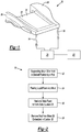
- Figure 1 illustrates a cushion 20 of a vehicle seat.
- the cushion 20 is formed by a molding process (described below) and includes a seat portion 22 having a substantially flat upper surface 24 and two side bolsters 26 each located on one side of the seat portion 22.
- the cushion 20 is made of foam.
- the cushion 20 is made of polyurethane foam.
- At least one motor 28 (shown in Figures 3, 4 and 5 ) is embedded within the cushion 20 at a desired location.
- the at least one motor 28 is completely embedded within the foam of the cushion 20 such that the at least one motor 28 is not visible when viewing an external surface of the cushion 20.
- the at least one motor 28 could be use with a cushion that includes pre-formed grooves in which the at least one motor 28 can be located.
- Figure 2 illustrates a method 30 of making the cushion 20.
- at least one motor 28 is suspended by a rod (not shown) or similar structure in a desired position within a mold (not shown).
- a rod with a magnetic tip or a mechanical device can be employed to retain the at least one motor 28 in the desired position.
- liquid foam is poured into the mold.
- the liquid foam is polyurethane foam.
- the foam is heated and/or baked, and the foam expands and solidifies to form the solid cushion 20.
- the at least one motor 28 is encapsulated and embedded in the foam of the cushion 20.
- the rod is then removed from the at least one motor 28, defining a hole in the foam of the cushion 20 where the rod was previously positioned. In one example, removal of the rod defines an approximately 6 mm diameter hole in the cushion 20 where the rod was previously located.
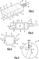
- Figures 3, 4 and 5 illustrate a motor 28 that is embedded in the cushion 20.
- the at least one motor 28 is a haptic motor.
- the at least one motor 28 is a vibration motor.
- the motor 28 includes a DC motor 40 and an eccentric weight 42, or a counter weight, located within a sealed housing 44.
- the housing 44 is made of nylon. There is no contact between the eccentric weight 42 and the housing 44. In one example, there is a minimum clearance of approximately 1.4 mm between the eccentric weight 42 and the housing 44. There is no looseness or rattle allowance between the DC motor 40 and the housing 44, preventing any abnormal noise due caused by DC motor 40 to housing 44 vibration. Additionally, there is no looseness or rattle between the eccentric weight 42 and a motor shaft 52.
- a wire harness subassembly 54 extends from the motor 28.
- the wire harness subassembly 54 is secured to the motor 28 by a grommet 82.
- the wire harness subassembly 54 allows communication between the motor 28 and a controller 79.
- the controller 79 is also in communication with a sensor 80 that detects a road event, as explained below.
- the housing 44 includes an upper portion 46 and a lower portion 48 secured together by welding.
- the upper portion 46 and the lower portion 48 are secured together by sonic welding. Once welded, the housing 44 is leak proof and sealed, which prevents the liquid foam from entering the housing 44 and affecting the operation of the at least one motor 28.
- the housing 44 also eliminates minimum free play or vibration loss in the housing 44.
- the upper portion 46 and the lower portion 48 are each substantially u-shaped.
- the housing 44 includes a top surface 72, a bottom surface 74, a first longitudinal surface 76 and a second longitudinal surface 78.
- the top surface 72 is substantially flat.
- the bottom surface 74 includes a portion that is substantially rounded.
- the shape of the housing 44 can be designed for maximum comfort.
- the surface area of the top surface 72 of the housing 46 is maximized (that is, it is substantially flat) to distribute the contact load over the broadest possible area without extending beyond the natural intrinsic width and length of the motor 28.
- the top surface 72 of the housing 44 is substantially parallel to a top surface 110 of the bolster 26 of the cushion 20 (shown in Figure 10 ).
- a strong bond forms between the upper portion 46 and the lower portion 48 of the housing 44 such that the housing 44 can accept pressure, such as the pressure applied by a knee of person when kneeling on the vehicle seat.
- a perimeter of each of the upper portion 46 and the lower portion 48 includes a projection 56 and 58, respectively, that engages a groove 64 and 66, respectively, of the other of the projections 56 and 58, respectively, when the upper portion 46 and the lower portion 48 are placed together.
- the projections 56 and 58 extend around an entire perimeter of the upper portion 46 and the lower portion 48, respectively, except at the location where the grommet 82 is received in the housing 44.
- the projection 58 of the lower portion 48 is located inwardly with respect to the projection 56 of the upper portion 46.
- One of the projections 56 and 58 includes a bead 68 that extends around the perimeter of the respective projection 56 and 58 and is located near a location of contact of the upper portion 46 and the lower portion 48 of the housing 44 when placed together.
- the bead 68 is located in the groove 64 of the upper portion 46 of the housing 44.
- the bead 68 has a generally triangular shape having a width X and a height Y. In one example, the width X is approximately 0.3 mm, and the height Y is approximately 0.3 mm.
- an adhesive 70 can be employed to secure the housing 44 to the foam of the cushion 20 when the at least one motor 28 is used with a cushion that includes pre-formed grooves in which the at least one motor 28 can be received.
- the adhesive 70 is double sided peel and stick tape.
- the adhesive 70 is applied to one or more of the top surface 72, the bottom surface 74, the first longitudinal surface 76 and the second longitudinal surface 78 of the housing 44.
- Figure 8 illustrates a perspective view of the cushion 20 including two motors 28 (shown in phantom) each embedded in one of the two bolsters 26.
- a mat 84 is located over the flat upper surface 24 of the seat portion 22 of the cushion 20.
- the mat 84 includes holes 86 that allow for ventilation.
- the mat 84 is made of polyester.
- Figure 9 illustrates a perspective of the cushion 20 including a piece of foam 88 located over each of the two motors 28 on an exterior surface of the cushion 20.
- a piece of foam 88 such as a mat, can be located over the two motors 28 to provide additional cushioning to protect the motors 28 and to also prevent the motors 28 from causing driver discomfort.
- each piece of foam 88 is made of polyurethane.
- Figure 10 illustrates a cross-sectional view of a portion of the cushion 20 taken along line A-A of Figure 8 .
- the foam material of the cushion 20 surrounds and is located above the motors 28 such that the motors 28 are embedded within the cushion 20 and are not visible when viewing the cushion 20 from an external perspective.
- a trim cover 104 is located over the cushion 20 and provides an external surface of the vehicle seat in which the driver sits while driving.
- the at least one motor 28 is positioned in the cushion 20 such that it will vibrate to provide a tactile signal that will be felt by the driver when activated by the controller 79. However, the at least one motor 28 is positioned to prevent pinching of and pressure on the driver. As explained below, the at least one motor 28 is positioned such that vibrations generated by the at least one motor 28 will be felt by the 5 th percentile female based on size and the 95 th percentile male based on size.
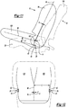
- Figure 11 illustrates a side view of a driver 90 sitting in a vehicle seat 92
- Figure 12 illustrates a top view of the driver 90 sitting in the vehicle seat 92
- a torso centerline 94 extends through a center body 96 of the driver 90 when seated in the vehicle seat 92
- a thigh centerline 98 is substantially parallel to a thigh 100 of the driver 90 when seated in the vehicle seat 92 and extends through the center body 96.
- the torso centerline 94 and the thigh center line 98 intersect at a point H, or the H point.
- a plane (not shown) is defined by the torso centerline 94 and the thigh centerline 98.
- a circle 102 is defined around the point H having a radius of Z. In one example, Z is approximately 12.5 mm.
- the center body 96 of the driver 90 rests against a backrest 106 of the vehicle seat 90, and the thigh 100 is positioned on the cushion 20.
- two motors 28 are each embedded in one of the side bolsters 26 of the cushion 20.
- the eccentric weight 42 of each motor 28 is positioned in the cushion 20 relative to the point H.
- the eccentric weight 42 of each motor 28 is positioned a distance of approximately A +/- 12.5 mm below the thigh centerline 98, approximately B mm +/- 12.5 mm from a side of the plane, and approximately C +/- 12.5 mm from a side of the thigh centerline 98.
- A is approximately 65 mm
- B is approximately 0 mm
- C is approximately 185 mm.
- the motors 28 are also positioned at least approximately 7.5 mm below an upper surface of the cushion 20.
- the optimal position of each of the motor 28 in the cushion 20 can be determined, and the motors 28 are then positioned in this location within the mold prior to pouring in the liquid foam to form the cushion 20.
- the at least one motor 28 is therefore positioned such that vibrations generated by the at least one motor 28 will be felt by the 5 th percentile female based on size and the 95 th percentile male based on size.
- the sensor 80 monitors a road event.
- a road event occurs when the vehicle moves from its lane, another vehicle is approaching, a front collision occurs, or a rear collision occurs.
- a signal is sent to the controller 79.
- the controller 79 then sends a signal to the at least one motor 28.
- the at least one motor 28 vibrates in the cushion 20 to provide a tactile signal that can be felt by the driver to alert the driver of the road event.
- the at least one motor 28 vibrates above 50 m/s 2 as measured at a seat-occupant interface at approximately 74 Hz.
Landscapes
- Engineering & Computer Science (AREA)
- Manufacturing & Machinery (AREA)
- Aviation & Aerospace Engineering (AREA)
- Transportation (AREA)
- Mechanical Engineering (AREA)
- Chair Legs, Seat Parts, And Backrests (AREA)
- Seats For Vehicles (AREA)
- Mattresses And Other Support Structures For Chairs And Beds (AREA)
- Vehicle Step Arrangements And Article Storage (AREA)
Description
- A driver can be exposed to numerous audio and visual signals and stimuli during driving. If an event occurs while driving, an audio or visual alert can be generated to obtain the driver's attention. In one example, an event occurs when a sensor detects that a vehicle deviates from its lane. However, due to numerous other audio and visual signals and stimuli to which the driver is exposed, an audio or visual alert might not get the attention of the driver.
- A tactile alert can be provided to alert the driver of an event. In one example, a motor located in a seat cushion vibrates when an event occurs to provide a tactile alert to the driver. Prior motors include a metal motor housing including portions that are secured together by fasteners. The metal housing is not water-resistant, and liquid foam cannot be used to form the seat cushion with the motor in place as the liquid foam could leak inside the metal housing. Therefore, the cushion is molded to include grooves that receive the motor. The motor is externally visible once the motor is positioned in one of the grooves. An additional pad may be located over the motor in the groove to provide a smooth surface.
GB2437158 - A seat cushion of a vehicle seat includes a cushion made of foam and at least one motor assembly located in the cushion. The at least one motor assembly includes a housing having a first portion and a second portion, and one of the first portion and the second portion includes a meltable feature located near a location of contact of the first portion and the second portion. The meltable feature melts to secure the first portion of the housing to the second portion of the housing to retain a motor within the housing.
- A vehicle seat system includes a cushion made of foam and at least one motor assembly located in the cushion. The at least one motor assembly includes a housing having a first portion and a second portion, and one of the first portion and the second portion includes a meltable feature located near a location of contact of the first portion and the second portion. The meltable feature melts to secure the first portion of the housing to the second portion of the housing to retain a motor within the housing, and the meltable feature is melted by sonic welding. The vehicle seat system also includes a sensor that detects a road event and sends a signal in response to the road event. The vehicle seat system also includes a controller that receives the signal from the sensor and sends another signal to the at least one motor to cause the at least one motor to vibrate in response to the road event.
- A method of forming a seat cushion of a vehicle seat includes the step of locating a motor in one of a first portion and a second portion of a housing. The method further includes the step of positioning the other of the first portion and the second portion of the housing on the one of the first portion and the second portion of the housing, and one of the first portion and the second portion of the housing includes a meltable feature located near a location of contact of the first portion and the second portion. The method further includes the step of melting the meltable feature to secure the first portion to the second portion together and to retain and seal the motor within the housing.
- These and other features of the present invention can be best understood from the following specification and drawings, the following of which is a brief description.
-
-
Figure 1 illustrates a perspective view of a cushion of a vehicle seat; -
Figure 2 illustrates a flowchart of a method of making the cushion; -
Figure 3 illustrates a perspective view of a motor showing internal components; -
Figure 4 illustrates a side cross-sectional view of the motor; -
Figure 5 illustrates a front cross-sectional view of the motor; -
Figure 6 illustrates a cross-sectional view of a housing of the motor including projections and grooves of each of an upper portion and a lower portion of the housing; -
Figure 7 illustrates a perspective view of the motor including an adhesive on the housing; -
Figure 8 illustrates a perspective view of the cushion with ventilation foam placed over an upper surface of the cushion; -
Figure 9 illustrates a perspective view of foam placed over the motors embedded in the cushion; -
Figure 10 illustrates a cross-sectional view of the cushion taken along lines A-A ofFigure 8 ; -
Figure 11 illustrate a side view of a driver sitting on the cushion of a vehicle seat including the motor; and -
Figure 12 illustrates a top view of the driver sitting on the cushion of the vehicle seat including the motor. -
Figure 1 illustrates acushion 20 of a vehicle seat. Thecushion 20 is formed by a molding process (described below) and includes aseat portion 22 having a substantially flatupper surface 24 and twoside bolsters 26 each located on one side of theseat portion 22. In one example, thecushion 20 is made of foam. In one example, thecushion 20 is made of polyurethane foam. - As discussed below, at least one motor 28 (shown in
Figures 3, 4 and 5 ) is embedded within thecushion 20 at a desired location. In one example, the at least onemotor 28 is completely embedded within the foam of thecushion 20 such that the at least onemotor 28 is not visible when viewing an external surface of thecushion 20. In another example, the at least onemotor 28 could be use with a cushion that includes pre-formed grooves in which the at least onemotor 28 can be located. In one example, there are twomotors 28 that are each embedded in one of the twoside bolsters 26. -
Figure 2 illustrates amethod 30 of making thecushion 20. Instep 32, at least onemotor 28 is suspended by a rod (not shown) or similar structure in a desired position within a mold (not shown). A rod with a magnetic tip or a mechanical device can be employed to retain the at least onemotor 28 in the desired position. Instep 34, liquid foam is poured into the mold. In one example, the liquid foam is polyurethane foam. Instep 36, the foam is heated and/or baked, and the foam expands and solidifies to form thesolid cushion 20. As a result, the at least onemotor 28 is encapsulated and embedded in the foam of thecushion 20. Instep 38, the rod is then removed from the at least onemotor 28, defining a hole in the foam of thecushion 20 where the rod was previously positioned. In one example, removal of the rod defines an approximately 6 mm diameter hole in thecushion 20 where the rod was previously located. -
Figures 3, 4 and 5 illustrate amotor 28 that is embedded in thecushion 20. In one example, the at least onemotor 28 is a haptic motor. In one example, the at least onemotor 28 is a vibration motor. Themotor 28 includes aDC motor 40 and aneccentric weight 42, or a counter weight, located within a sealedhousing 44. In one example, thehousing 44 is made of nylon. There is no contact between theeccentric weight 42 and thehousing 44. In one example, there is a minimum clearance of approximately 1.4 mm between theeccentric weight 42 and thehousing 44. There is no looseness or rattle allowance between theDC motor 40 and thehousing 44, preventing any abnormal noise due caused byDC motor 40 to housing 44 vibration. Additionally, there is no looseness or rattle between theeccentric weight 42 and amotor shaft 52. Finally, as thehousing 44 is sealed, the rotating parts of themotor 42 are protected from the environment, preventing erosion and corrosion. Awire harness subassembly 54 extends from themotor 28. Thewire harness subassembly 54 is secured to themotor 28 by agrommet 82. - Returning to
Figure 1 , thewire harness subassembly 54 allows communication between themotor 28 and acontroller 79. Thecontroller 79 is also in communication with asensor 80 that detects a road event, as explained below. - The
housing 44 includes anupper portion 46 and alower portion 48 secured together by welding. In one example, theupper portion 46 and thelower portion 48 are secured together by sonic welding. Once welded, thehousing 44 is leak proof and sealed, which prevents the liquid foam from entering thehousing 44 and affecting the operation of the at least onemotor 28. Thehousing 44 also eliminates minimum free play or vibration loss in thehousing 44. In one example, theupper portion 46 and thelower portion 48 are each substantially u-shaped. - As shown in
Figure 5 , thehousing 44 includes atop surface 72, abottom surface 74, a firstlongitudinal surface 76 and a secondlongitudinal surface 78. In one example, thetop surface 72 is substantially flat. In one example, thebottom surface 74 includes a portion that is substantially rounded. - The shape of the
housing 44 can be designed for maximum comfort. The surface area of thetop surface 72 of thehousing 46 is maximized (that is, it is substantially flat) to distribute the contact load over the broadest possible area without extending beyond the natural intrinsic width and length of themotor 28. In one example, thetop surface 72 of thehousing 44 is substantially parallel to atop surface 110 of the bolster 26 of the cushion 20 (shown inFigure 10 ). A strong bond forms between theupper portion 46 and thelower portion 48 of thehousing 44 such that thehousing 44 can accept pressure, such as the pressure applied by a knee of person when kneeling on the vehicle seat. - As show in
Figure 6 , a perimeter of each of theupper portion 46 and thelower portion 48 includes aprojection groove projections upper portion 46 and thelower portion 48 are placed together. Theprojections upper portion 46 and thelower portion 48, respectively, except at the location where thegrommet 82 is received in thehousing 44. In one example, theprojection 58 of thelower portion 48 is located inwardly with respect to theprojection 56 of theupper portion 46. - One of the
projections respective projection upper portion 46 and thelower portion 48 of thehousing 44 when placed together. In one example, the bead 68 is located in thegroove 64 of theupper portion 46 of thehousing 44. In one example, the bead 68 has a generally triangular shape having a width X and a height Y. In one example, the width X is approximately 0.3 mm, and the height Y is approximately 0.3 mm. When theupper portion 46 and thelower portion 48 are positioned together and are sonic welded, the bead 68 melts and fills in thegrooves upper portion 46 and thelower portion 48 together. - As shown in
Figure 7 , in one example, an adhesive 70 can be employed to secure thehousing 44 to the foam of thecushion 20 when the at least onemotor 28 is used with a cushion that includes pre-formed grooves in which the at least onemotor 28 can be received. In one example, the adhesive 70 is double sided peel and stick tape. In one example, the adhesive 70 is applied to one or more of thetop surface 72, thebottom surface 74, the firstlongitudinal surface 76 and the secondlongitudinal surface 78 of thehousing 44. However, it is possible for no adhesive to be employed as thehousing 44 of themotor 28 is embedded in the foam of thecushion 20 during the molding process described inFigure 2 . -
Figure 8 illustrates a perspective view of thecushion 20 including two motors 28 (shown in phantom) each embedded in one of the two bolsters 26. Amat 84 is located over the flatupper surface 24 of theseat portion 22 of thecushion 20. Themat 84 includesholes 86 that allow for ventilation. In one example, themat 84 is made of polyester. -
Figure 9 illustrates a perspective of thecushion 20 including a piece offoam 88 located over each of the twomotors 28 on an exterior surface of thecushion 20. In one example, a piece offoam 88, such as a mat, can be located over the twomotors 28 to provide additional cushioning to protect themotors 28 and to also prevent themotors 28 from causing driver discomfort. In one example, each piece offoam 88 is made of polyurethane. However, in another example, there is no piece offoam 88 located over each of the twomotors 28 as the embedding of the twomotors 28 in thecushion 20 provides cushioning. -
Figure 10 illustrates a cross-sectional view of a portion of thecushion 20 taken along line A-A ofFigure 8 . As shown, the foam material of thecushion 20 surrounds and is located above themotors 28 such that themotors 28 are embedded within thecushion 20 and are not visible when viewing thecushion 20 from an external perspective. Atrim cover 104 is located over thecushion 20 and provides an external surface of the vehicle seat in which the driver sits while driving. - The at least one
motor 28 is positioned in thecushion 20 such that it will vibrate to provide a tactile signal that will be felt by the driver when activated by thecontroller 79. However, the at least onemotor 28 is positioned to prevent pinching of and pressure on the driver. As explained below, the at least onemotor 28 is positioned such that vibrations generated by the at least onemotor 28 will be felt by the 5th percentile female based on size and the 95th percentile male based on size. -
Figure 11 illustrates a side view of adriver 90 sitting in avehicle seat 92, andFigure 12 illustrates a top view of thedriver 90 sitting in thevehicle seat 92. Atorso centerline 94 extends through acenter body 96 of thedriver 90 when seated in thevehicle seat 92. Athigh centerline 98 is substantially parallel to athigh 100 of thedriver 90 when seated in thevehicle seat 92 and extends through thecenter body 96. Thetorso centerline 94 and thethigh center line 98 intersect at a point H, or the H point. A plane (not shown) is defined by thetorso centerline 94 and thethigh centerline 98. Acircle 102 is defined around the point H having a radius of Z. In one example, Z is approximately 12.5 mm. Thecenter body 96 of thedriver 90 rests against abackrest 106 of thevehicle seat 90, and thethigh 100 is positioned on thecushion 20. - As shown in
Figures 11 and 12 , twomotors 28 are each embedded in one of the side bolsters 26 of thecushion 20. Theeccentric weight 42 of eachmotor 28 is positioned in thecushion 20 relative to the point H. Theeccentric weight 42 of eachmotor 28 is positioned a distance of approximately A +/- 12.5 mm below thethigh centerline 98, approximately B mm +/- 12.5 mm from a side of the plane, and approximately C +/- 12.5 mm from a side of thethigh centerline 98. In one example, A is approximately 65 mm, B is approximately 0 mm, and C is approximately 185 mm. Themotors 28 are also positioned at least approximately 7.5 mm below an upper surface of thecushion 20. - By using these values and ranges to determine the position of each of the two
motors 28, the optimal position of each of themotor 28 in thecushion 20 can be determined, and themotors 28 are then positioned in this location within the mold prior to pouring in the liquid foam to form thecushion 20. The at least onemotor 28 is therefore positioned such that vibrations generated by the at least onemotor 28 will be felt by the 5th percentile female based on size and the 95th percentile male based on size. - Returning to
Figure 1 , thesensor 80 monitors a road event. In one example, a road event occurs when the vehicle moves from its lane, another vehicle is approaching, a front collision occurs, or a rear collision occurs. When thesensor 80 detects a road event, a signal is sent to thecontroller 79. Thecontroller 79 then sends a signal to the at least onemotor 28. In response to the signal from thecontroller 79, the at least onemotor 28 vibrates in thecushion 20 to provide a tactile signal that can be felt by the driver to alert the driver of the road event. In one example, the at least onemotor 28 vibrates above 50 m/s2 as measured at a seat-occupant interface at approximately 74 Hz. - The foregoing description is only exemplary of the principles of the invention. Many modifications and variations are possible in light of the above teachings, for instance, the inlet vanes may also have intermediate positions. It is, therefore, to be understood that within the scope of the appended claims, the invention may be practiced otherwise than using the example embodiments which have been specifically described. For that reason the following claims should be studied to determine the true scope and content of this invention.
Claims (15)
- A seat cushion of a vehicle seat, the seat cushion comprising:a cushion (20) made of foam; andat least one motor assembly (28) located in the cushion, wherein the at least one motor assembly (28) includes a housing (44) having a first portion (46) and a second portion (48), one of the first portion (46) and the second portion (48) includes a meltable feature located near a location of contact of the first portion (46) and the second portion (48), and the meltable feature melts to secure the first portion (46) of the housing to the second portion (48) of the housing to retain a motor (40) within the housing (44).
- A vehicle seat system comprising a seat cushion as recited in claim 1, further wherein
the meltable feature is melted by sonic welding, and the vehicle seat system including a sensor (80) that detects a road event and sends a signal in response to
the road event, and a controller (79) that receives the signal from the sensor (80) and sends another signal to the at least one motor (28) to cause the at least one motor (28) to vibrate in response to the road event. - The seat cushion as recited in claim 1 or the vehicle seat system as recited in claim 2 wherein the cushion (20) is made of polyurethane foam.
- The seat cushion as recited in claim 1 or the vehicle seat system as recited in claim 2 wherein the cushion (20) includes a seat portion (22) having a substantially flat surface (24) and a bolster (26) on each side of the seat portion (22), the at least one motor assembly (28) includes two motor assemblies, and one of the at least one motor assembly (28) is located in one of the two bolsters (26).
- The seat cushion as recited in claim 1 or the vehicle seat system as recited in claim 2 wherein the housing (44) is made of nylon.
- The seat cushion as recited in claim 1 wherein the meltable feature is melted by sonic welding.
- The seat cushion as recited in claim 1 or the vehicle seat system as recited in claim 2 wherein the meltable feature is a bead (68) extending around a perimeter of one of the first portion (46) and the second portion (48) of the housing (44).
- The seat cushion as recited in claim 1 or the vehicle seat system as recited in claim 2 wherein the first portion (46) and the second portion (48) of the housing (44) each include a projection (56, 58) that extends around a perimeter of the first portion (46) and the second portion (48), and the projection (56) of the first portion (46) is received in a groove (66) of the second portion (48), and the projection (58) of the second portion (48) is received in a groove (64) of the first portion (46).
- The seat cushion as recited in claim 1 or the vehicle seat system as recited in claim 2 wherein the at least one motor (28) vibrates in response to a road event.
- The seat cushion or the vehicle seat system as recited in claim 9 wherein a sensor (80) detects the road event, sends a signal to a controller (79), and the controller (79) sends another signal to the at least one motor (28) to cause the at least one motor (28) to vibrate.
- The seat cushion as recited in claim 1 or the vehicle seat system as recited in claim 2 wherein one of the first portion (46) and the second portion (48) of the housing (44) is an upper portion (46) and the other of the first portion (46) and the second portion (48) of the housing (44) is a lower portion (48), and the upper portion (46) includes a substantially flat surface (72) and the lower portion (48)_includes a substantially rounded surface (74).
- The seat cushion or the vehicle seat system as recited in claim 11 wherein the substantially flat surface (72) of the upper portion (46) of the housing (44) is substantially parallel to a top surface (24) of the cushion (20).
- The seat cushion as recited in claim 1 or the vehicle seat system as recited in claim 2 wherein, when a driver (90) is seated in a vehicle seat including the cushion (20), a point (H) is defined at an intersection of a torso centerline (94) extending through a center body (96) of the driver (90) and a thigh centerline (98) substantially parallel to a thigh (100) of the driver (90) and extending through the center body (96) of the driver (90), and a plane is defined by the torso centerline (94) and the thigh centerline (98), and an eccentric mass (42) of the at least one motor (28) is positioned a distance of approximately 65 mm +/- 12.5 mm below the thigh centerline (98), approximately 0 mm +/- 12.5 mm from a side of the torso centerline (94), and approximately 185 mm +/- 12.5 mm from a side of the plane.
- A method of forming a seat cushion of a vehicle seat, the method comprising the steps of:locating a motor (40) in one of a first portion (46) and a second portion (48) of a housing (44);positioning the other of the first portion (46) and the second portion (48) of the housing (44) on the one of the first portion (46) and the second portion (48) of the housing (44), wherein one of the first portion (46) and the second portion (48) of the housing (44) includes a meltable feature located near a location of contact of the first portion (46) and the second portion (48);melting the meltable feature to secure the first portion (46) to the second portion (48) together and to retain and seal the motor (40) within the housing (44).
- The method as recited in claim 14 further including the steps of:positioning the at least one motor (40) in a desired position within a mold;pouring a liquid foam into the mold; andheating the liquid form to form a solid foam to locate the at least one motor in the solid foam.
Priority Applications (1)
| Application Number | Priority Date | Filing Date | Title |
|---|---|---|---|
| PL13724986T PL2849930T3 (en) | 2012-05-18 | 2013-05-08 | Haptic motor |
Applications Claiming Priority (2)
| Application Number | Priority Date | Filing Date | Title |
|---|---|---|---|
| US13/475,081 US10214128B2 (en) | 2012-05-18 | 2012-05-18 | Haptic motor |
| PCT/US2013/040034 WO2013173136A1 (en) | 2012-05-18 | 2013-05-08 | Haptic motor |
Publications (2)
| Publication Number | Publication Date |
|---|---|
| EP2849930A1 EP2849930A1 (en) | 2015-03-25 |
| EP2849930B1 true EP2849930B1 (en) | 2017-11-08 |
Family
ID=48485481
Family Applications (1)
| Application Number | Title | Priority Date | Filing Date |
|---|---|---|---|
| EP13724986.8A Not-in-force EP2849930B1 (en) | 2012-05-18 | 2013-05-08 | Haptic motor |
Country Status (9)
| Country | Link |
|---|---|
| US (2) | US10214128B2 (en) |
| EP (1) | EP2849930B1 (en) |
| JP (2) | JP2015516335A (en) |
| AR (1) | AR091357A1 (en) |
| BR (1) | BR112014028771A2 (en) |
| CA (1) | CA2873371C (en) |
| MX (1) | MX366069B (en) |
| PL (1) | PL2849930T3 (en) |
| WO (1) | WO2013173136A1 (en) |
Families Citing this family (7)
| Publication number | Priority date | Publication date | Assignee | Title |
|---|---|---|---|---|
| CN109195835B (en) * | 2016-04-05 | 2021-12-24 | 帝人芳纶有限公司 | Haptic assembly |
| FR3056168B1 (en) * | 2016-09-16 | 2021-12-24 | Faurecia Interieur Ind | VEHICLE INTERIOR DRESSING WITH HAPTIC FEEDBACK |
| FR3066963B1 (en) * | 2017-06-02 | 2019-06-21 | Peugeot Citroen Automobiles Sa | VIBRATION WARNING DEVICE FOR VEHICLE SEAT. |
| JP6925930B2 (en) * | 2017-10-20 | 2021-08-25 | 株式会社タチエス | Vehicle seat |
| CN112638707B (en) | 2018-09-03 | 2023-04-18 | 提爱思科技股份有限公司 | Vehicle seat |
| JP7633498B2 (en) * | 2021-03-18 | 2025-02-20 | テイ・エス テック株式会社 | Vehicle seat |
| US20240367562A1 (en) * | 2021-09-13 | 2024-11-07 | Sears Manufacturing Co. | Magnetic Heated Seat Device |
Family Cites Families (28)
| Publication number | Priority date | Publication date | Assignee | Title |
|---|---|---|---|---|
| US2920618A (en) | 1958-04-28 | 1960-01-12 | Oster Mfg Co John | Vibratory therapeutic cushion |
| US3455296A (en) | 1966-05-18 | 1969-07-15 | Cloyse L Mccaleb | Vibrator attachment for vehicle seats |
| ZA752595B (en) | 1974-05-15 | 1976-03-31 | Ici Ltd | Improvements in and relating to the packaging of flowable materials |
| JPS50155374U (en) * | 1974-06-12 | 1975-12-23 | ||
| JPH0586253U (en) | 1991-09-03 | 1993-11-22 | 関東自動車工業株式会社 | Seat vibrator mounting structure |
| US5498061A (en) | 1992-12-04 | 1996-03-12 | Fukuoka Kagaku Ltd. | Apparatus for vibrating seats |
| US6087942A (en) | 1998-05-18 | 2000-07-11 | Jb Research, Inc. | Tactile alert and massaging system |
| JP3037306B1 (en) | 1998-12-22 | 2000-04-24 | 愛三工業株式会社 | Canister |
| US6682494B1 (en) | 1999-08-17 | 2004-01-27 | Inseat Solutions, Llc | Massaging system having isolated vibrators |
| DE10022434A1 (en) * | 2000-05-09 | 2001-11-22 | Daimler Chrysler Ag | Dynamic adaptation of vehicle seat to support body when cornering, determines adjustment from stored and current road and vehicle data, allowing for inherent delay |
| US6619739B2 (en) * | 2001-03-01 | 2003-09-16 | L & P Property Management Company | Universal ergonomic support with self-contained actuator |
| US20040049323A1 (en) | 2002-09-05 | 2004-03-11 | Ford Global Technologies, Inc. | Haptic seat notification system |
| JP4523795B2 (en) | 2004-04-30 | 2010-08-11 | シロキ工業株式会社 | Electric unlocking lock device for vehicle back door |
| JP4453514B2 (en) | 2004-06-09 | 2010-04-21 | 日産自動車株式会社 | VEHICLE DRIVE OPERATION ASSISTANCE DEVICE AND VEHICLE HAVING VEHICLE DRIVE OPERATION ASSISTANCE DEVICE |
| CN2907059Y (en) | 2005-09-03 | 2007-05-30 | 金龙控股集团有限公司 | Micro iron core motor |
| JP2007116788A (en) * | 2005-10-18 | 2007-05-10 | Nippon Sharyo Seizo Kaisha Ltd | Power generator base |
| US7714701B2 (en) | 2005-11-16 | 2010-05-11 | Gm Global Technology Operations, Inc. | Active material based haptic alert system |
| US7439507B2 (en) | 2005-12-29 | 2008-10-21 | Delphi Technologies, Inc. | Apparatus and method for thermal side detection in a vehicle |
| US7681949B2 (en) | 2006-04-12 | 2010-03-23 | Lear Corporation | Haptic vehicle seat |
| JPWO2007116788A1 (en) | 2006-04-12 | 2009-08-20 | 株式会社ミクニ | Electric actuator |
| US7676324B2 (en) | 2006-05-25 | 2010-03-09 | Gm Global Technology Operations, Inc. | Alerting a vehicle operator to traffic movement |
| US7551068B2 (en) | 2006-08-28 | 2009-06-23 | Lear Corporation | Vehicle seat alert system |
| JP5052850B2 (en) | 2006-09-21 | 2012-10-17 | 豊達電機(香港)有限公司 | Ultrasonic welding and joining method of speaker cabinet and speaker cabinet manufactured thereby |
| DE102007012132A1 (en) * | 2007-03-14 | 2008-09-18 | Daimler Ag | Warning apparatus for use in bus, has vibration transmitter arranged in driver's seat such that its vibrations are transferred only by materials to fixed parts of seat, which has anti-vibration characteristics |
| US8141947B2 (en) | 2007-07-12 | 2012-03-27 | Lear Corporation | Haptic seating system |
| US8072317B2 (en) * | 2008-07-16 | 2011-12-06 | Johnson Electric S.A. | Haptic solenoid system |
| DE102008036605A1 (en) | 2008-08-06 | 2010-02-11 | Trw Automotive Gmbh | Method for assembly of belt buckle shell housing, involves providing two lock housing half shells made of plastic with joining surfaces |
| JP2012002342A (en) | 2010-06-21 | 2012-01-05 | Sato Light Kogyo Kk | Airtight pressure vessel and manufacturing method of the same |
-
2012
- 2012-05-18 US US13/475,081 patent/US10214128B2/en not_active Expired - Fee Related
-
2013
- 2013-05-08 MX MX2014013934A patent/MX366069B/en active IP Right Grant
- 2013-05-08 PL PL13724986T patent/PL2849930T3/en unknown
- 2013-05-08 BR BR112014028771A patent/BR112014028771A2/en active Search and Examination
- 2013-05-08 JP JP2015512689A patent/JP2015516335A/en active Pending
- 2013-05-08 EP EP13724986.8A patent/EP2849930B1/en not_active Not-in-force
- 2013-05-08 WO PCT/US2013/040034 patent/WO2013173136A1/en not_active Ceased
- 2013-05-08 CA CA2873371A patent/CA2873371C/en not_active Expired - Fee Related
- 2013-05-17 AR ARP130101726 patent/AR091357A1/en active IP Right Grant
-
2017
- 2017-09-22 JP JP2017181905A patent/JP6476254B2/en not_active Expired - Fee Related
-
2018
- 2018-11-26 US US16/199,503 patent/US20190111817A1/en not_active Abandoned
Non-Patent Citations (1)
| Title |
|---|
| None * |
Also Published As
| Publication number | Publication date |
|---|---|
| US20130307302A1 (en) | 2013-11-21 |
| PL2849930T3 (en) | 2018-04-30 |
| US20190111817A1 (en) | 2019-04-18 |
| WO2013173136A1 (en) | 2013-11-21 |
| JP2015516335A (en) | 2015-06-11 |
| BR112014028771A2 (en) | 2017-08-08 |
| JP2017218152A (en) | 2017-12-14 |
| US10214128B2 (en) | 2019-02-26 |
| JP6476254B2 (en) | 2019-02-27 |
| AR091357A1 (en) | 2015-01-28 |
| CA2873371A1 (en) | 2013-11-21 |
| MX2014013934A (en) | 2015-04-13 |
| EP2849930A1 (en) | 2015-03-25 |
| MX366069B (en) | 2019-06-26 |
| CA2873371C (en) | 2020-04-28 |
Similar Documents
| Publication | Publication Date | Title |
|---|---|---|
| US20190111817A1 (en) | Haptic motor | |
| JP6127255B2 (en) | Vibration alarm patch | |
| US9573503B2 (en) | Vehicle seat | |
| CN103569013B (en) | Caution system and method for vehicle | |
| GB2437158A (en) | Haptic vehicle seat with vibration generators | |
| JP4958154B2 (en) | Motorcycle | |
| US20060255920A1 (en) | Annunciating device for vehicle | |
| CN201932077U (en) | Driving seat vibration type reminding device | |
| EP0442692B1 (en) | Seam stabiliser for covers of foam bodies | |
| JP2009120015A (en) | Vehicle seat and vehicle alarm device | |
| WO2005049391A1 (en) | Apparatus and method for positioning reinforcement material within an interior trim panel | |
| JP6877461B2 (en) | Tactile assembly | |
| JP2009255809A (en) | Vehicular seat equipped with notification device | |
| JP2010511569A (en) | Airbag deployment device | |
| JP6925930B2 (en) | Vehicle seat | |
| JP2009214578A (en) | Vehicular seat | |
| US9592784B2 (en) | Vehicle seat and manufacturing method of seat pad | |
| JP2017065643A (en) | Vehicle seat and alarm device for vehicle | |
| JP2007083942A (en) | Seat belt warning device | |
| CN205686361U (en) | A kind of safety belt reminding device and automotive seat | |
| JP2009214579A (en) | Vehicular seat | |
| JP6135578B2 (en) | Vehicle seat | |
| JPH09182647A (en) | Seat device | |
| EP2625070B1 (en) | Trim element for motor vehicle adapted to optimum deployment of inflatable bag device | |
| JPH0324149Y2 (en) |
Legal Events
| Date | Code | Title | Description |
|---|---|---|---|
| PUAI | Public reference made under article 153(3) epc to a published international application that has entered the european phase |
Free format text: ORIGINAL CODE: 0009012 |
|
| 17P | Request for examination filed |
Effective date: 20141209 |
|
| AK | Designated contracting states |
Kind code of ref document: A1 Designated state(s): AL AT BE BG CH CY CZ DE DK EE ES FI FR GB GR HR HU IE IS IT LI LT LU LV MC MK MT NL NO PL PT RO RS SE SI SK SM TR |
|
| AX | Request for extension of the european patent |
Extension state: BA ME |
|
| RIN1 | Information on inventor provided before grant (corrected) |
Inventor name: KNOEBEL, ALICE Inventor name: FRANZ, MICHAEL DAVID Inventor name: ROCKWELL, CHRISTOPHER MARK Inventor name: VISWANATHAN, ANUP Inventor name: WIEGAND, DANIEL JEROME Inventor name: KRUEGER JR., DOUGLAS J. |
|
| DAX | Request for extension of the european patent (deleted) | ||
| REG | Reference to a national code |
Ref country code: DE Ref legal event code: R079 Ref document number: 602013029074 Country of ref document: DE Free format text: PREVIOUS MAIN CLASS: B29C0065080000 Ipc: B60N0002440000 |
|
| GRAP | Despatch of communication of intention to grant a patent |
Free format text: ORIGINAL CODE: EPIDOSNIGR1 |
|
| RIC1 | Information provided on ipc code assigned before grant |
Ipc: B29L 31/00 20060101ALI20170620BHEP Ipc: B60N 2/44 20060101AFI20170620BHEP Ipc: B29L 31/34 20060101ALI20170620BHEP Ipc: B29C 65/00 20060101ALI20170620BHEP Ipc: B60N 2/70 20060101ALI20170620BHEP Ipc: B29C 65/08 20060101ALI20170620BHEP |
|
| INTG | Intention to grant announced |
Effective date: 20170712 |
|
| GRAS | Grant fee paid |
Free format text: ORIGINAL CODE: EPIDOSNIGR3 |
|
| GRAA | (expected) grant |
Free format text: ORIGINAL CODE: 0009210 |
|
| AK | Designated contracting states |
Kind code of ref document: B1 Designated state(s): AL AT BE BG CH CY CZ DE DK EE ES FI FR GB GR HR HU IE IS IT LI LT LU LV MC MK MT NL NO PL PT RO RS SE SI SK SM TR |
|
| REG | Reference to a national code |
Ref country code: GB Ref legal event code: FG4D |
|
| REG | Reference to a national code |
Ref country code: CH Ref legal event code: EP Ref country code: AT Ref legal event code: REF Ref document number: 943814 Country of ref document: AT Kind code of ref document: T Effective date: 20171115 |
|
| REG | Reference to a national code |
Ref country code: DE Ref legal event code: R079 Ref document number: 602013029074 Country of ref document: DE Free format text: PREVIOUS MAIN CLASS: B60N0002440000 Ipc: B60N0002900000 |
|
| REG | Reference to a national code |
Ref country code: IE Ref legal event code: FG4D |
|
| REG | Reference to a national code |
Ref country code: DE Ref legal event code: R096 Ref document number: 602013029074 Country of ref document: DE |
|
| REG | Reference to a national code |
Ref country code: NL Ref legal event code: MP Effective date: 20171108 |
|
| REG | Reference to a national code |
Ref country code: LT Ref legal event code: MG4D |
|
| REG | Reference to a national code |
Ref country code: FR Ref legal event code: PLFP Year of fee payment: 6 |
|
| REG | Reference to a national code |
Ref country code: AT Ref legal event code: MK05 Ref document number: 943814 Country of ref document: AT Kind code of ref document: T Effective date: 20171108 |
|
| PG25 | Lapsed in a contracting state [announced via postgrant information from national office to epo] |
Ref country code: NO Free format text: LAPSE BECAUSE OF FAILURE TO SUBMIT A TRANSLATION OF THE DESCRIPTION OR TO PAY THE FEE WITHIN THE PRESCRIBED TIME-LIMIT Effective date: 20180208 Ref country code: LT Free format text: LAPSE BECAUSE OF FAILURE TO SUBMIT A TRANSLATION OF THE DESCRIPTION OR TO PAY THE FEE WITHIN THE PRESCRIBED TIME-LIMIT Effective date: 20171108 Ref country code: NL Free format text: LAPSE BECAUSE OF FAILURE TO SUBMIT A TRANSLATION OF THE DESCRIPTION OR TO PAY THE FEE WITHIN THE PRESCRIBED TIME-LIMIT Effective date: 20171108 Ref country code: SE Free format text: LAPSE BECAUSE OF FAILURE TO SUBMIT A TRANSLATION OF THE DESCRIPTION OR TO PAY THE FEE WITHIN THE PRESCRIBED TIME-LIMIT Effective date: 20171108 Ref country code: ES Free format text: LAPSE BECAUSE OF FAILURE TO SUBMIT A TRANSLATION OF THE DESCRIPTION OR TO PAY THE FEE WITHIN THE PRESCRIBED TIME-LIMIT Effective date: 20171108 Ref country code: FI Free format text: LAPSE BECAUSE OF FAILURE TO SUBMIT A TRANSLATION OF THE DESCRIPTION OR TO PAY THE FEE WITHIN THE PRESCRIBED TIME-LIMIT Effective date: 20171108 |
|
| PG25 | Lapsed in a contracting state [announced via postgrant information from national office to epo] |
Ref country code: IS Free format text: LAPSE BECAUSE OF FAILURE TO SUBMIT A TRANSLATION OF THE DESCRIPTION OR TO PAY THE FEE WITHIN THE PRESCRIBED TIME-LIMIT Effective date: 20180308 Ref country code: AT Free format text: LAPSE BECAUSE OF FAILURE TO SUBMIT A TRANSLATION OF THE DESCRIPTION OR TO PAY THE FEE WITHIN THE PRESCRIBED TIME-LIMIT Effective date: 20171108 Ref country code: GR Free format text: LAPSE BECAUSE OF FAILURE TO SUBMIT A TRANSLATION OF THE DESCRIPTION OR TO PAY THE FEE WITHIN THE PRESCRIBED TIME-LIMIT Effective date: 20180209 Ref country code: BG Free format text: LAPSE BECAUSE OF FAILURE TO SUBMIT A TRANSLATION OF THE DESCRIPTION OR TO PAY THE FEE WITHIN THE PRESCRIBED TIME-LIMIT Effective date: 20180208 Ref country code: RS Free format text: LAPSE BECAUSE OF FAILURE TO SUBMIT A TRANSLATION OF THE DESCRIPTION OR TO PAY THE FEE WITHIN THE PRESCRIBED TIME-LIMIT Effective date: 20171108 Ref country code: HR Free format text: LAPSE BECAUSE OF FAILURE TO SUBMIT A TRANSLATION OF THE DESCRIPTION OR TO PAY THE FEE WITHIN THE PRESCRIBED TIME-LIMIT Effective date: 20171108 Ref country code: LV Free format text: LAPSE BECAUSE OF FAILURE TO SUBMIT A TRANSLATION OF THE DESCRIPTION OR TO PAY THE FEE WITHIN THE PRESCRIBED TIME-LIMIT Effective date: 20171108 |
|
| PG25 | Lapsed in a contracting state [announced via postgrant information from national office to epo] |
Ref country code: CZ Free format text: LAPSE BECAUSE OF FAILURE TO SUBMIT A TRANSLATION OF THE DESCRIPTION OR TO PAY THE FEE WITHIN THE PRESCRIBED TIME-LIMIT Effective date: 20171108 Ref country code: SK Free format text: LAPSE BECAUSE OF FAILURE TO SUBMIT A TRANSLATION OF THE DESCRIPTION OR TO PAY THE FEE WITHIN THE PRESCRIBED TIME-LIMIT Effective date: 20171108 Ref country code: DK Free format text: LAPSE BECAUSE OF FAILURE TO SUBMIT A TRANSLATION OF THE DESCRIPTION OR TO PAY THE FEE WITHIN THE PRESCRIBED TIME-LIMIT Effective date: 20171108 Ref country code: CY Free format text: LAPSE BECAUSE OF FAILURE TO SUBMIT A TRANSLATION OF THE DESCRIPTION OR TO PAY THE FEE WITHIN THE PRESCRIBED TIME-LIMIT Effective date: 20171108 Ref country code: EE Free format text: LAPSE BECAUSE OF FAILURE TO SUBMIT A TRANSLATION OF THE DESCRIPTION OR TO PAY THE FEE WITHIN THE PRESCRIBED TIME-LIMIT Effective date: 20171108 |
|
| REG | Reference to a national code |
Ref country code: DE Ref legal event code: R097 Ref document number: 602013029074 Country of ref document: DE |
|
| PG25 | Lapsed in a contracting state [announced via postgrant information from national office to epo] |
Ref country code: RO Free format text: LAPSE BECAUSE OF FAILURE TO SUBMIT A TRANSLATION OF THE DESCRIPTION OR TO PAY THE FEE WITHIN THE PRESCRIBED TIME-LIMIT Effective date: 20171108 Ref country code: SM Free format text: LAPSE BECAUSE OF FAILURE TO SUBMIT A TRANSLATION OF THE DESCRIPTION OR TO PAY THE FEE WITHIN THE PRESCRIBED TIME-LIMIT Effective date: 20171108 |
|
| PLBE | No opposition filed within time limit |
Free format text: ORIGINAL CODE: 0009261 |
|
| STAA | Information on the status of an ep patent application or granted ep patent |
Free format text: STATUS: NO OPPOSITION FILED WITHIN TIME LIMIT |
|
| 26N | No opposition filed |
Effective date: 20180809 |
|
| PG25 | Lapsed in a contracting state [announced via postgrant information from national office to epo] |
Ref country code: SI Free format text: LAPSE BECAUSE OF FAILURE TO SUBMIT A TRANSLATION OF THE DESCRIPTION OR TO PAY THE FEE WITHIN THE PRESCRIBED TIME-LIMIT Effective date: 20171108 |
|
| REG | Reference to a national code |
Ref country code: CH Ref legal event code: PL |
|
| GBPC | Gb: european patent ceased through non-payment of renewal fee |
Effective date: 20180508 |
|
| PG25 | Lapsed in a contracting state [announced via postgrant information from national office to epo] |
Ref country code: MC Free format text: LAPSE BECAUSE OF FAILURE TO SUBMIT A TRANSLATION OF THE DESCRIPTION OR TO PAY THE FEE WITHIN THE PRESCRIBED TIME-LIMIT Effective date: 20171108 |
|
| REG | Reference to a national code |
Ref country code: IE Ref legal event code: MM4A |
|
| PG25 | Lapsed in a contracting state [announced via postgrant information from national office to epo] |
Ref country code: CH Free format text: LAPSE BECAUSE OF NON-PAYMENT OF DUE FEES Effective date: 20180531 Ref country code: LI Free format text: LAPSE BECAUSE OF NON-PAYMENT OF DUE FEES Effective date: 20180531 |
|
| PG25 | Lapsed in a contracting state [announced via postgrant information from national office to epo] |
Ref country code: LU Free format text: LAPSE BECAUSE OF NON-PAYMENT OF DUE FEES Effective date: 20180508 |
|
| PG25 | Lapsed in a contracting state [announced via postgrant information from national office to epo] |
Ref country code: IE Free format text: LAPSE BECAUSE OF NON-PAYMENT OF DUE FEES Effective date: 20180508 Ref country code: GB Free format text: LAPSE BECAUSE OF NON-PAYMENT OF DUE FEES Effective date: 20180508 |
|
| PG25 | Lapsed in a contracting state [announced via postgrant information from national office to epo] |
Ref country code: MT Free format text: LAPSE BECAUSE OF NON-PAYMENT OF DUE FEES Effective date: 20180508 |
|
| PG25 | Lapsed in a contracting state [announced via postgrant information from national office to epo] |
Ref country code: HU Free format text: LAPSE BECAUSE OF FAILURE TO SUBMIT A TRANSLATION OF THE DESCRIPTION OR TO PAY THE FEE WITHIN THE PRESCRIBED TIME-LIMIT; INVALID AB INITIO Effective date: 20130508 Ref country code: PT Free format text: LAPSE BECAUSE OF FAILURE TO SUBMIT A TRANSLATION OF THE DESCRIPTION OR TO PAY THE FEE WITHIN THE PRESCRIBED TIME-LIMIT Effective date: 20171108 |
|
| PG25 | Lapsed in a contracting state [announced via postgrant information from national office to epo] |
Ref country code: MK Free format text: LAPSE BECAUSE OF NON-PAYMENT OF DUE FEES Effective date: 20171108 |
|
| PG25 | Lapsed in a contracting state [announced via postgrant information from national office to epo] |
Ref country code: AL Free format text: LAPSE BECAUSE OF FAILURE TO SUBMIT A TRANSLATION OF THE DESCRIPTION OR TO PAY THE FEE WITHIN THE PRESCRIBED TIME-LIMIT Effective date: 20171108 |
|
| PGFP | Annual fee paid to national office [announced via postgrant information from national office to epo] |
Ref country code: TR Payment date: 20200508 Year of fee payment: 8 Ref country code: DE Payment date: 20200428 Year of fee payment: 8 Ref country code: FR Payment date: 20200414 Year of fee payment: 8 |
|
| PGFP | Annual fee paid to national office [announced via postgrant information from national office to epo] |
Ref country code: IT Payment date: 20200414 Year of fee payment: 8 Ref country code: PL Payment date: 20200403 Year of fee payment: 8 Ref country code: BE Payment date: 20200416 Year of fee payment: 8 |
|
| REG | Reference to a national code |
Ref country code: DE Ref legal event code: R119 Ref document number: 602013029074 Country of ref document: DE |
|
| REG | Reference to a national code |
Ref country code: BE Ref legal event code: MM Effective date: 20210531 |
|
| PG25 | Lapsed in a contracting state [announced via postgrant information from national office to epo] |
Ref country code: DE Free format text: LAPSE BECAUSE OF NON-PAYMENT OF DUE FEES Effective date: 20211201 |
|
| PG25 | Lapsed in a contracting state [announced via postgrant information from national office to epo] |
Ref country code: FR Free format text: LAPSE BECAUSE OF NON-PAYMENT OF DUE FEES Effective date: 20210531 |
|
| PG25 | Lapsed in a contracting state [announced via postgrant information from national office to epo] |
Ref country code: BE Free format text: LAPSE BECAUSE OF NON-PAYMENT OF DUE FEES Effective date: 20210531 |
|
| PG25 | Lapsed in a contracting state [announced via postgrant information from national office to epo] |
Ref country code: PL Free format text: LAPSE BECAUSE OF NON-PAYMENT OF DUE FEES Effective date: 20210508 |
|
| PG25 | Lapsed in a contracting state [announced via postgrant information from national office to epo] |
Ref country code: IT Free format text: LAPSE BECAUSE OF NON-PAYMENT OF DUE FEES Effective date: 20200508 |
|
| PG25 | Lapsed in a contracting state [announced via postgrant information from national office to epo] |
Ref country code: TR Free format text: LAPSE BECAUSE OF NON-PAYMENT OF DUE FEES Effective date: 20210508 |
|
| PG25 | Lapsed in a contracting state [announced via postgrant information from national office to epo] |
Ref country code: IT Free format text: LAPSE BECAUSE OF NON-PAYMENT OF DUE FEES Effective date: 20210508 |