EP2849711B1 - Apparatus and method for attaching discrete web segments - Google Patents
Apparatus and method for attaching discrete web segments Download PDFInfo
- Publication number
- EP2849711B1 EP2849711B1 EP13791194.7A EP13791194A EP2849711B1 EP 2849711 B1 EP2849711 B1 EP 2849711B1 EP 13791194 A EP13791194 A EP 13791194A EP 2849711 B1 EP2849711 B1 EP 2849711B1
- Authority
- EP
- European Patent Office
- Prior art keywords
- segment
- transfer
- location
- pick
- discrete
- Prior art date
- Legal status (The legal status is an assumption and is not a legal conclusion. Google has not performed a legal analysis and makes no representation as to the accuracy of the status listed.)
- Active
Links
Images



Classifications
-
- A—HUMAN NECESSITIES
- A61—MEDICAL OR VETERINARY SCIENCE; HYGIENE
- A61F—FILTERS IMPLANTABLE INTO BLOOD VESSELS; PROSTHESES; DEVICES PROVIDING PATENCY TO, OR PREVENTING COLLAPSING OF, TUBULAR STRUCTURES OF THE BODY, e.g. STENTS; ORTHOPAEDIC, NURSING OR CONTRACEPTIVE DEVICES; FOMENTATION; TREATMENT OR PROTECTION OF EYES OR EARS; BANDAGES, DRESSINGS OR ABSORBENT PADS; FIRST-AID KITS
- A61F13/00—Bandages or dressings; Absorbent pads
- A61F13/15—Absorbent pads, e.g. sanitary towels, swabs or tampons for external or internal application to the body; Supporting or fastening means therefor; Tampon applicators
- A61F13/15577—Apparatus or processes for manufacturing
- A61F13/15707—Mechanical treatment, e.g. notching, twisting, compressing, shaping
- A61F13/15747—Folding; Pleating; Coiling; Stacking; Packaging
-
- A—HUMAN NECESSITIES
- A61—MEDICAL OR VETERINARY SCIENCE; HYGIENE
- A61F—FILTERS IMPLANTABLE INTO BLOOD VESSELS; PROSTHESES; DEVICES PROVIDING PATENCY TO, OR PREVENTING COLLAPSING OF, TUBULAR STRUCTURES OF THE BODY, e.g. STENTS; ORTHOPAEDIC, NURSING OR CONTRACEPTIVE DEVICES; FOMENTATION; TREATMENT OR PROTECTION OF EYES OR EARS; BANDAGES, DRESSINGS OR ABSORBENT PADS; FIRST-AID KITS
- A61F13/00—Bandages or dressings; Absorbent pads
- A61F13/15—Absorbent pads, e.g. sanitary towels, swabs or tampons for external or internal application to the body; Supporting or fastening means therefor; Tampon applicators
- A61F13/15577—Apparatus or processes for manufacturing
- A61F13/15756—Applying tabs, strips, tapes, loops; Knotting the ends of pads
-
- A—HUMAN NECESSITIES
- A61—MEDICAL OR VETERINARY SCIENCE; HYGIENE
- A61F—FILTERS IMPLANTABLE INTO BLOOD VESSELS; PROSTHESES; DEVICES PROVIDING PATENCY TO, OR PREVENTING COLLAPSING OF, TUBULAR STRUCTURES OF THE BODY, e.g. STENTS; ORTHOPAEDIC, NURSING OR CONTRACEPTIVE DEVICES; FOMENTATION; TREATMENT OR PROTECTION OF EYES OR EARS; BANDAGES, DRESSINGS OR ABSORBENT PADS; FIRST-AID KITS
- A61F13/00—Bandages or dressings; Absorbent pads
- A61F13/15—Absorbent pads, e.g. sanitary towels, swabs or tampons for external or internal application to the body; Supporting or fastening means therefor; Tampon applicators
- A61F13/15577—Apparatus or processes for manufacturing
-
- A—HUMAN NECESSITIES
- A61—MEDICAL OR VETERINARY SCIENCE; HYGIENE
- A61F—FILTERS IMPLANTABLE INTO BLOOD VESSELS; PROSTHESES; DEVICES PROVIDING PATENCY TO, OR PREVENTING COLLAPSING OF, TUBULAR STRUCTURES OF THE BODY, e.g. STENTS; ORTHOPAEDIC, NURSING OR CONTRACEPTIVE DEVICES; FOMENTATION; TREATMENT OR PROTECTION OF EYES OR EARS; BANDAGES, DRESSINGS OR ABSORBENT PADS; FIRST-AID KITS
- A61F13/00—Bandages or dressings; Absorbent pads
- A61F13/15—Absorbent pads, e.g. sanitary towels, swabs or tampons for external or internal application to the body; Supporting or fastening means therefor; Tampon applicators
- A61F13/15577—Apparatus or processes for manufacturing
- A61F13/15764—Transferring, feeding or handling devices; Drives
-
- A—HUMAN NECESSITIES
- A61—MEDICAL OR VETERINARY SCIENCE; HYGIENE
- A61F—FILTERS IMPLANTABLE INTO BLOOD VESSELS; PROSTHESES; DEVICES PROVIDING PATENCY TO, OR PREVENTING COLLAPSING OF, TUBULAR STRUCTURES OF THE BODY, e.g. STENTS; ORTHOPAEDIC, NURSING OR CONTRACEPTIVE DEVICES; FOMENTATION; TREATMENT OR PROTECTION OF EYES OR EARS; BANDAGES, DRESSINGS OR ABSORBENT PADS; FIRST-AID KITS
- A61F13/00—Bandages or dressings; Absorbent pads
- A61F13/15—Absorbent pads, e.g. sanitary towels, swabs or tampons for external or internal application to the body; Supporting or fastening means therefor; Tampon applicators
- A61F13/15577—Apparatus or processes for manufacturing
- A61F2013/15821—Apparatus or processes for manufacturing characterized by the apparatus for manufacturing
-
- Y—GENERAL TAGGING OF NEW TECHNOLOGICAL DEVELOPMENTS; GENERAL TAGGING OF CROSS-SECTIONAL TECHNOLOGIES SPANNING OVER SEVERAL SECTIONS OF THE IPC; TECHNICAL SUBJECTS COVERED BY FORMER USPC CROSS-REFERENCE ART COLLECTIONS [XRACs] AND DIGESTS
- Y10—TECHNICAL SUBJECTS COVERED BY FORMER USPC
- Y10T—TECHNICAL SUBJECTS COVERED BY FORMER US CLASSIFICATION
- Y10T29/00—Metal working
- Y10T29/49—Method of mechanical manufacture
- Y10T29/49826—Assembling or joining
-
- Y—GENERAL TAGGING OF NEW TECHNOLOGICAL DEVELOPMENTS; GENERAL TAGGING OF CROSS-SECTIONAL TECHNOLOGIES SPANNING OVER SEVERAL SECTIONS OF THE IPC; TECHNICAL SUBJECTS COVERED BY FORMER USPC CROSS-REFERENCE ART COLLECTIONS [XRACs] AND DIGESTS
- Y10—TECHNICAL SUBJECTS COVERED BY FORMER USPC
- Y10T—TECHNICAL SUBJECTS COVERED BY FORMER US CLASSIFICATION
- Y10T29/00—Metal working
- Y10T29/53—Means to assemble or disassemble
Definitions
- the field of the invention relates generally to web handling apparatus and more specifically to web handling apparatus adapted to attach discrete web segments together to form a continuous web and a method of using the apparatus.
- disposable absorbent products in their everyday lives including, for example, disposable absorbent articles such as adult incontinence products, enuresis pants, training pants, and diapers. Many manufacturers of these absorbent articles seek to better meet the needs of users. For example, there is an ongoing need to improve fit, discretion, and leakage protection for many of these articles.
- Some absorbent articles employ elasticization across the front and/or back of the article to keep the article snug against the wearer during use. Some of these articles employ a multiplicity of elastic strands within front and/or back waist panels of the article to provide the elasticization, while others employ elastomeric polymeric films, which are often sandwiched with one or more nonwoven layers.
- absorbent articles include an absorbent member, constructed from wood pulp fluff, superabsorbent polymers, and/or other absorbent material to absorb fluids (e.g., urine) discharged by the user.
- the absorbent member is typically positioned in the crotch region of the article and extends forward and backward into the article's front and/or back regions.
- the elastic members that extend across the front and/or back waist panels of the article overlap the absorbent member at various locations since the absorbent member extends forward/backward into the front/back waist regions of the article.
- Some absorbent articles include refastenable seams disposed along the sides of the article to enable the wearer or a caregiver to remove the article by detaching the front region from the back region along the seams. Because the refastenble seams are located along the sides of the article, some wearers find the seams difficult to manipulate. Refastenable side seams can also be difficult for some caregivers of bedridden individuals to manipulate.
- US 2012/0061016 discloses a method of making prefastened refastenable disposable absorbent articles.
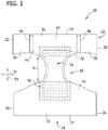
- FIGS 1 and 2 illustrate one suitable embodiment of an absorbent article, indicated generally at 10.
- the absorbent article 10 has a front region 12, a back region 14, and a crotch region 16 disposed longitudinally between and interconnecting the front and back regions.
- the front, back and crotch regions 12, 14, 16 are indicated generally by the respective reference number.
- the absorbent article 10 has a front edge 18 and transversely opposed first and second front side edges 20, 22.
- a back edge 24 and transversely opposed first and second back side edges 26, 28 are located in the back region 14 of the absorbent article 10.
- the absorbent article 10 defines a longitudinal direction 30 and a transverse direction 32 perpendicular to the longitudinal direction.
- the absorbent article 10 includes an absorbent insert, indicated generally at 34, that extends longitudinally from the front region 12 through the crotch region 16 to the back region 14.
- the absorbent insert 34 can be constructed of materials suitable for absorbing liquid excretions, such as wood pulp fluff, superabsorbent polymers, absorbent foam, and the like.
- the absorbent insert 34 can be encased in one or more substrates.
- the absorbent insert 34 can be wrapped in a tissue and/or a nonwoven substrate.
- the front and back regions 12, 14 of the absorbent article 10 are constructed of separate pieces of laminate 36, 37 that are interconnected via the absorbent insert 34. That is, the front region 12 is formed by a piece of laminate 36 and the back region 14 is formed by a separate piece of laminate 37. As seen in Figure 1 , the laminate 36 forming the front region 12 is spaced from the laminate 37 forming the back region 14 to define a gap G. The absorbent insert 34 spans the gap G and connects the laminate 36 forming the front region 12 to the laminate 37 forming the back region 14.
- a portion of the absorbent insert 34 overlaps a portion of each of the laminates 36, 37 in the front and back regions 12, 14 to define overlapped regions 42 and non-overlapped regions 44.
- at least a portion of each of the overlapped regions 42 of the laminate 36 is non-elastomeric, and at least a portion of the non-overlapped region 44 of the laminate 36 is elastomeric.
- the overlapped regions 42 are indicated in Figure 1 by a pattern of diagonally extending dashes.
- each of the laminates 36, 37 forming the overlapped regions 42 in the front and back regions 12, 14 is constructed entirely of an elastomeric film laminate having portions thereof “deactivated” or “deadened” to render it non-elastomeric.
- elastomeric refers to a material or composite that can be elongated by at least 50 percent of its relaxed length and that will recover, upon release of the applied force, at least 50 percent of its elongation. It is generally preferred that the elastomeric material or composite be capable of being elongated by at least 100 percent, more preferably by at least 200 percent, of its relaxed length and recover, upon release of an applied force, at least 50 percent of its elongation.
- Non-elastomeric refers to a material or composite that is non-extensible, or that is extensible but will recover no more than 20 percent of its elongated length after release of an applied elongating force.
- Non-extensible refers to a material that cannot stretch or extend by more than 25 percent of its relaxed length without fracture upon application of a biasing force.
- Partially elastomeric refers to a material or composite which can be elongated by at least 50 percent of its relaxed length and which will recover, upon release of the applied force, more than 20 percent but less than 50 percent of its elongation.
- the laminates are to be examined with any separately attached components removed.
- the absorbent insert 34 should be removed before examining the extensible or elastic properties of the overlapped regions 42 of the laminates 36, 37. That is, the absorbent insert 34 should be peeled away from the laminates 36, 37 prior to examining the extensibility or elasticity of any portion of the laminates.
- the majority of the overlapped region 42 of each of the laminates 36, 37 is non-elastomeric. That is, more than 50 percent of the area of the overlapped region 42 of the laminates 36, 37 is non-elastomeric. In one suitable embodiment, more than 75 percent, and in still a more suitable embodiment, more than 90 percent of the area of the overlapped region 42 of the laminates 36 is non-elastomeric. In another suitable embodiment, the entire overlapped region 42 of the laminates 36, 37 (i.e., 100 percent) is non-elastomeric. For example, in the absorbent article 10 illustrated in Figure 1 , the entire overlapped region 42 of the laminates 36, 37 is non-elastomeric and generally the same size and shape as the portion of the absorbent insert 34 that overlaps it.
- the portion of the laminates 36, 37 rendered non-elastomeric can be larger than the corresponding overlapped region 42.
- the non-elastomeric area of the laminates 36, 37 can be 125 percent or less larger, more preferably 120 percent or less larger, and still more preferably 110 percent or less larger in area than the overlapped region 42.
- the footprint of the non-elastomeric region of the laminates 36, 37 being larger relative to the footprint of the absorbent insert 34 in the front and back regions 12, 14 of the absorbent article 10 allows for variability in registration as the absorbent insert is mated to the laminates.
- the relatively larger non-elastomeric region (larger relative to the overlapped region 42) will aid in minimizing the amount of bunching directly around the periphery of the absorbent insert 34, which can provide a smoother, "flatter", more underwear-like garment.
- the laminate 36 used to form the front region 12 of the absorbent article 10 comprises a center panel 57 and a pair of side panels 58, 60.
- one of the panels 58 extends outward from one side (i.e., the right side as viewed in Figure 1 ) of the center panel 57 and the other panel 60 extends outward from the other side (i.e., the left side as viewed in Figure 1 ) of the center panel.
- the side panels 58, 60 have properties or characteristics that are different than properties or characteristics of the center panel 57.
- each of the side panels 58, 60 are more elastic or stretchable than the center panel. It is understood that the side panels 58, 60 can have other properties (e.g., strength) in addition to or instead of elasticity or stretchability that differ from the center panel.
- the center panel 57 of the front region 12 comprises a polymeric film layer and at least one nonwoven layer.
- the center panel 57 comprises two nonwoven layers superposed on opposing top and bottom surfaces of the polymeric film layer such that the polymeric film layer is sandwiched between the two nonwoven layers.
- the polymeric film layer and both nonwoven layers extend substantially throughout the entire area of the center panel.
- each of the side panels 58, 60 of the front region also comprise a polymeric film layer and at least one nonwoven layer. More specific, each of the side panels 58, 60 comprises two nonwoven layers superposed on opposing top and bottom surfaces of the polymeric film layer such that the polymeric film layer is sandwiched between the two nonwoven layers.
- the material(s) used to form the side panels 58, 60 are more elastic or stretchable than the material(s) used to form the center panel 57. It is understood, however, that the material(s) used to form the side panels 58, 60 can have other properties (e.g., strength) in addition to or instead of elasticity or stretchability that differ from the material(s) used to form the center panel 57.
- the laminate 37 used to form the back region 14 of the absorbent article 10 comprises a polymeric film layer and at least one nonwoven layer.
- the laminate 37 has two nonwoven layers superposed on opposing top and bottom surfaces of the polymeric film layer such that the polymeric film layer is sandwiched between the two nonwoven layers.
- the polymeric film layer and both nonwoven layers extend substantially throughout the entire area of the laminate 37. While the laminate 37 used to form the back region 14 is the same throughout the back region in the illustrated absorbent article 10, it is contemplated that different laminates or materials can be used in different parts of the back region.
- the material(s) used to form the center panel 57 of the front region 12 and the laminate 37 of the back region 14 are substantially the same. It is understood, however, that the material(s) used to form the center panel 57 of the front region 12 can be different than those used to form the laminate 37 of the back region 14 of the absorbent article 10.
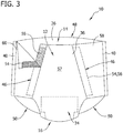
- the front region 12 of the absorbent article 10 is joined to the back region 14 via a pair of non-refastenable butt seams 40 to define a pull-on, pant-like configuration of the absorbent article having a waist opening, indicated at 48, and two leg openings, indicated at 50. More specifically, a portion of the front region 12 adjacent the first and second front side edges 20, 22 of the front region 12 are joined to a portion of the back region 14 adjacent the first and second back side edges 26, 28 of the back region 14. While Figures 2 and 3 illustrate the front and back regions 12, 14 being joined together via butt seams 40, it is understood that the front and back regions can be joined together via other types of non-refastenable seams (e.g., overlapping seams).
- non-refastenable seams e.g., overlapping seams
- the absorbent article 10 includes at least one fastening assembly, indicated generally at 46, disposed in the front region 12 of the absorbent article.
- the fastening assembly 46 includes a left-handed fastening assembly member attached to one of the side panels 58 of the front region 12, and a right-handed fastening assembly attached to the other side panel 60 of the front region 12.
- Each of the fastening assemblies 46 includes a pair of fastener members 54, 56 that are attached to the front region 12 in spaced relationship with the butt seams 40. Thus, each of the fastener members 54, 56 is spaced from the back region 14 of the absorbent article 10.
- the absorbent article 10 can be selectively moved between an opened configuration wherein at least one of the fastening assemblies 46 are disengaged (i.e., where the fastener members 54, 56 not attached), and a closed configuration wherein both of the fastening assemblies are engaged (i.e., wherein the fastener members 54, 56 attached).
- the fastening assemblies 46 can be angled relative to the longitudinal direction 30 of the absorbent article 10.
- the fastener members 54 on the side panels 58, 60 comprise hook fasteners and the other fastener members 56 comprise complementary loop fasteners.
- the fastener members 54 on the side panels 58, 60 can comprise loop fasteners and the other fastener members 56 can comprise complementary hook fasteners.
- the loop fasteners can be formed integral with either the side panels 58, 60 or the center panel 57 such that the complementary hook fastener can be engaged anywhere on the respective side panel or center panel.
- the fastener members 54, 56 can comprise other suitable fasteners, adhesive or cohesive fastening elements such as an adhesive fastener and an adhesive-receptive landing zone or material, or the like.
- Figure 4 illustrates a plurality of absorbent articles 10 (e.g., three absorbent articles being illustrated in Figure 4 ) in the process of being manufactured. More specifically, Figure 4 illustrates the plurality of absorbent articles 10 moving in a cross-machine direction (indicated by arrow 71) and prior to being cut into discrete articles 10 along cut lines 73. As seen in Figure 4 , each of the front regions 12 of the illustrated articles 10 are formed from a continuous web 75 and each of the back regions 14 of are formed from a separate continuous web 77.
- the absorbent inserts 34 which are discrete pieces, have been bonded in spaced relationship with each other along the length of the continuous webs 75, 77.
- the continuous web 77 forming the back regions 14 of the absorbent articles 10 is formed from a single material (e.g., laminate 37).
- the continuous web 75 forming the front regions 12 of the illustrated articles 10 is formed from discrete segments of at least two different materials. More specifically, the continuous web 75 forming the front regions 12 of the articles 10 comprises a plurality of first discrete segments 79 and a plurality of second discrete segments 81. As seen in Fig. 4 , the first and second discrete segments 79, 81 overlap each other and are connected to each other within the overlap.
- the first discrete segments 79 has a first length 94 and the second discrete segments 81 a second length 96 that is less than the first length.
- each of the first discrete segments 79 defines the center panel 57 of one of the absorbent articles 10 and each of the second discrete segments 81 defines one of the side panels 60 of a leading absorbent article and one of the side panels 58 of a trailing absorbent article. That is, each of the second discrete segments defines two side panels 58, 60, with each of the side panels being located on different (adjacent) absorbent articles 10.
- back region 14 of the articles 10 can be formed from discrete segments instead of or in addition to the front region 12 of the article being formed from discrete segments. It is also contemplated that the first and second discrete segments 79, 81 can have substantially the same length or that the first length 94 of the first discrete segment can be less than the second length 96 of the second discrete segment. It is further contemplated that the first and second discrete segments 79, 81 can be formed from the same material instead of different materials as illustrated in Figures 4 and 5 .
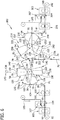
- FIG. 6 schematically illustrates a portion of one suitable embodiment of an apparatus, indicated generally at 100, for making the continuous web 75 illustrated in Figures 4 and 5 and used to form the front region 12 of the illustrated absorbent article 10.
- a supply of web 90 e.g., a web of material suitable for the center part 57 of the front region 12 of the absorbent article 10) used to form the first discrete segment 79 of the absorbent article 10 is provided from a suitable supply source (e.g., supply roll 92).
- a suitable supply source e.g., supply roll 92
- the web 90 is fed from the supply roll 92 by a web transfer device, indicated generally at 102, to a bonding station, indicated generally at 104.
- One of the fastener member (e.g., in the illustrated embodiment, loop fastener member 56) are bonded to the web 90 at the bonding station 104.
- the loop fastener members 56 are bonded (e.g., thermally bonded, point bonded, adhesively bonded) to the continuous web 90.
- the loop fastener members 56 are fed to the bonding station 104 from a continuous supply web 105 after they have been cut into suitably sized segments by a cutting device, indicated generally at 107 (e.g., a knife and anvil roll as seen in Figure 6 ).
- a cutting device indicated generally at 107
- the web 90 can be made from materials suitable for use as the loop fastener members 56.
- the supply web 105, the cutting device 107 and bonding station 104 can be eliminated.
- the web 90 having loop fastener members 56 bonded thereto is then fed to a suitable cutting device, indicated at 106.
- the cutting device 106 is arranged to perforate each of the loop fastener members 56 and the portion of the web 90 underlying the loop fastener members 56 to define a line of weakness extending in a cross-machine direction of the web. It is contemplated that the cutting device 106 can be arranged to cut (i.e., sever) or otherwise form lines of weakness on the loop fastener members 56 and the underlying web portion.
- the web 90 is then fed to a first segment transfer device, indicated generally at 110. More specifically, the first segment transfer device 110 receives the web 90 as it is traveling in a first direction, represented by arrow A1.
- the web 90 includes a plurality of first segments separated by the lines of weakness (i.e., perforations) formed in the web by the cutting device 106. It is contemplated, however, that the plurality of first segments can be fed to the first segment transfer device 110 as separate segments. That is, a plurality of first discrete segments 79 can be individually fed to the first segment transfer device 110. It is also contemplated that the web 90 can be cut into a plurality of first discrete segments 79 while the web is disposed on the first segment transfer device 110.
- the first segment transfer device 110 includes a drive assembly 118 configured to rotate about a drive axis 120, and a plurality of transfer elements 122 coupled to and extend outward from the drive assembly.
- the drive assembly 118 includes one or more suitable drive sources including, for example, servo motors, and/or camboxes, operatively connected to each of the transfer elements 122. More specifically, the drive source(s) of the drive assembly 118 is configured to rotate each transfer element 122 about the drive axis 120 between a pick-up location, indicated generally at 124, and an application (or drop-off) location, indicated generally at 126. In the illustrated embodiment, the drive assembly 118 is configured to rotate each of the transfer elements 122 in a clockwise direction (as viewed in Figure 6 ).
- each of the transfer elements 122 is configured to receive the web 90 at the pick-up location 124, and convey each of the first discrete segments 79 to the application location 126.
- each of the first discrete segments 79 is separated from an adjacent first discrete segment along the preformed perforation (or other line of weakness) as the web 90 is initially conveyed by the first segment transfer device 110. More specifically, each of the first discrete segments 79 is received by one of the transfer elements 122 while it is still connected to the web 90.
- two of the transfer elements 122 are disposed in close proximity to each other as the web 90 is initially received by the first segment transfer device 110.
- the web 90 can be continuous fed to the first segment transfer device 110 with each of the first discrete segments 79 being received by one of the transfer elements 122.
- each of the transfer elements 122 rotates along a first variable speed profile.
- the transfer elements 122 of the first segment transfer device 110 rotate at variable speeds during each revolution.
- each of the transfer elements 122 rotates at a first transfer speed (as measured at the outer surface of the transfer element 122).
- the first transfer speed of the transfer elements 122 approximately matches the speed at which the web 90 of first discrete segments 79 is being fed to the first segment transfer device 110.
- the drive assembly 118 accelerates the transfer element to a second, faster transfer speed.
- the accelerated transfer element 122 separates from the adjacent, trailing transfer element.
- the two transfer elements 122 that were adjacent at the pick-up location 124 are moved apart which causes the web 90 of first discrete segments 79 to rupture about the preformed perforations and thereby separate the first discrete segment from the web.
- each of the first discrete segments 79 is attached to one of the second discrete segments 81 at the application location 126 to form the continuous web 75. After the first discrete segment 79 traveling on the transfer element 122 is attached to second discrete segments 81, the first discrete segment is released from the transfer element.
- the first variable speed profile of the first segment transfer device 110 comprises accelerating each of the transfer elements 122 from the first transfer speed at the pick-up location 124 to the second, faster transfer speed at the application location 126 and then decelerating each of the transfer elements from the second transfer speed to the first transfer speed as the transfer element rotates from the application location back to the pick-up location. It is understood, however, that the first segment transfer device 110 can have a different speed profile without departing from some aspects of this invention.
- the first segment transfer device 110 is an oscillating cam adjusted roller as is disclosed in U.S. Pat. Nos. 5,716,478 , 5,759,340 , and 6,139,004 , all of which are assigned to Kimberly-Clark Worldwide, Inc. It is understood, however, that the first segment transfer device 110 can comprise other types of suitable web accelerators. For example, in another suitable embodiment, the first segment transfer device 110 can comprise known slip-cut apparatus.
- each of the transfer elements 122 includes a support arm 128 extending radially outwardly from the drive assembly 118, and a transfer puck 130 rotatably coupled to the support arm 128.
- the support arm 128 includes a first end, which is coupled to the drive assembly 118, and an opposite second end, which is coupled to the transfer puck 130.
- the support arm 128 extends between the first end and the second end along a radial axis 136 of the transfer element 122.
- the first end of the support arm 128 is coupled to the drive assembly 118 such that each transfer puck 130 is independently rotatable about both the drive axis 120 of the first segment transfer device 110 (as indicated by arrow 143 of Figure 6 ) and the radial axis (as indicated by arrow 145 of Figure 6 ). It is understood, however, that each of the transfer elements 122 can be fixed to inhibit rotation of the corresponding transfer puck 130 about the radial axis 136.
- each transfer puck 130 includes a leading edge 138, a trailing edge 140, and a platform 142 that extends between the leading edge and the trailing edge.
- the platform 142 of each of the transfer pucks 130 is sized and shaped to receive and hold one of the first discrete segments 79.
- the first discrete segments 79 can be held to the transfer puck 130 by vacuum, surface roughness and/or needle engagement.
- the transfer puck 130 can include a raised pad (e.g., a polymer insert) for receiving each of the loop fastener members 56.
- the raised pad can be used to increase the engagement pressure (i.e., compression) between the fastener members 54, 56 at the application location 126.
- the transfer puck 130 is pivotable about the support arm axis 136.
- the orientation of each of the transfer pucks 130 can be adjusted or altered.
- the orientation of the first discrete segments 79 can be adjusted or altered as it is received by the first segment transfer device 110.
- each of the first discrete segments 79 can be received on the transfer pucks 130 in a first orientation (e.g., a machine direction), such as at the pick-up location 124 and rotated to a second orientation (e.g., a cross-machine direction) prior to the application location 126.
- a first orientation e.g., a machine direction
- a second orientation e.g., a cross-machine direction
- each of the first discrete segments 79 can be fed to the first segment transfer device 110 in the machine direction (or the cross-machine direction) at the pick-up location 124 and rotated such that each of the first discrete segments 79 is in the cross-machine direction (or the machine direction) at the application location 126.
- a supply of second web 190 (e.g., a web of material suitable for the side panels 58, 60 of the front region 12 of the absorbent article 10) used to form the second discrete segment 81 of the absorbent article 10 is provided from a suitable supply source (e.g., supply roll 192).
- a suitable supply source e.g., supply roll 192
- the web 190 is fed from the supply roll 192 by a web transfer device, indicated generally at 202, to a bonding station, indicated generally at 204.
- One of the fastener members (e.g., in the illustrated embodiment, hook fastener member 54) is bonded to the web 190 at the bonding station 204.
- the hook fastener members 54 are bonded (e.g., thermally bonded, point bonded, adhesively bonded) to the continuous web 190.
- the hook fastener members 54 are fed to the bonding station 204 from a continuous supply web 205 after they have been cut into suitably sized segments by a suitable cutting device, indicated generally at 207 (e.g., a knife and anvil roll as seen in Figure 6 ).
- the web 190 having hook fastener members 54 bonded thereto is fed to a suitable cutting device, indicated at 206.
- the cutting device 206 is arranged to perforate each of the hook fastener members 54 and the portion of the web 190 underlying the hook fastener members to define a line of weakness extending in a cross-machine direction of the web. It is contemplated that cutting device 206 can be arranged to cut (or sever) or otherwise form lines of weakness on the hook fastener members 54 and the underlying web portion.
- the web 190 is fed to a second segment transfer device, indicated generally at 210. More specifically, the second segment transfer device 210 receives the web 190 as it is traveling in a first direction, represented by arrow B1.
- the web 190 includes a plurality of second discrete segments 81 separated by the lines of weakness (i.e., perforations) formed in the web by the cutting device 206. It is contemplated that the web 190 can be cut into a plurality of second discrete segments 81 while the web is disposed on the second segment transfer device 210.
- the second segment transfer device 210 includes a drive assembly 218 configured to rotate about a drive axis 220, and a plurality of transfer elements 222 coupled to and extend outward from the drive assembly.
- the drive assembly 218 includes one or more suitable drive sources including, for example, servo motors, and/or camboxes, operatively connected to each of the transfer elements 222. More specifically, the drive source(s) of the drive assembly 218 is configured to rotate each transfer element 222 about the drive axis 220 between a pick-up location, indicated generally at 224, and the application location 126. In the illustrated embodiment, the drive assembly 218 is configured to rotate each of the transfer elements 222 in a counterclockwise direction (as viewed in Figure 6 ).
- each of the transfer elements 222 is configured to receive the web 190 at the pick-up location 224, and convey each of the second discrete segments 81 to the application location 126.
- each of the second segments is separated from an adjacent segment along the preformed perforation (or other line of weakness) as the web 190 is initially conveyed by the second segment transfer device 210. More specifically, each of the second segments is received by one of the transfer elements 222 while it is still connected to the web 190.
- two of the transfer elements 222 are disposed in close proximity to each other as the web 190 is initially received by the second segment transfer device 210.
- the web 190 can be continuous fed to the second segment transfer device 210 with each of the second discrete segments 81 being received by one of the transfer elements 222.
- each of the transfer elements 222 rotate along a second variable speed profile.
- the transfer elements 222 of the second segment transfer device 210 rotate at variable speeds during each revolution.
- each of the transfer elements 222 rotates at a first transfer speed (as measured at the outer surface of the transfer element 222).
- the first transfer speed of the transfer elements 222 approximately matches the speed at which the web 190 of second discrete segments 81 is being fed to the second segment transfer device 210.
- the drive assembly 218 accelerates the transfer element to a second, faster transfer speed.
- the accelerated transfer element 222 separates from the adjacent, trailing transfer element.
- the two transfer elements 222 that were adjacent at the pick-up location 224 are moved apart which causes the web 190 of second discrete segments 81 to rupture about the preformed perforations and thereby separate the second discrete segment from the web.
- each of the second discrete segments 81 is attached to one of the first discrete segments 79 at the application location 126 to form the continuous web 75. More specifically, in the illustrated embodiment, the leading loop fastener member 54 bonded to the second discrete segment 81 carried by one of the transfer element 222 of the second segment transfer device 210 is pressed into engagement with a trailing hook fastener member 56 bonded to one of first discrete segments 79 carried by one of the transfer elements 122 of the first segment transfer device 110 at the application location 126.
- the trailing loop fastener member 54 of the same second discrete segment 81 is then pressed into engagement with a leading hook fastener member 56 bonded to a different, trialing first discrete segment 79 (i.e., the first discrete segment 79 being carried by the following transfer element 122) at the application location 126. This process is continued to form continuous web 75.
- the continuous web 75 is defined by a plurality of alternating first and second discrete segments 79, 81 with the first and second discrete segments being secured to each other by hook and loop fastener members 54, 76. It is contemplated that the alternating first and second discrete segments 79, 81 can be releasably secured to each other in other suitable ways or can be non-releasably secured (i.e., bonded) to each other without departing from some aspects of this invention.
- the first and second discrete segments 79, 81 can be non-releasable secured together at the application location 126 by adhesive bonding, ultrasonic bonding, cohesive bonding, pressure bonding, and/or thermal bonding.
- each of the transfer elements 222 decelerate from the second speed back to the slower, first speed as it approaches the pick-up location 224.
- the second variable speed profile of the second segment transfer device 210 comprises accelerating each of the transfer elements 222 from the first transfer speed at the pick-up location 224 to the second, faster transfer speed at the application location 126 and then decelerating each of the transfer elements from the second transfer speed to the first transfer speed as the transfer element rotates from the application location back to the pick-up location. It is understood, however, that the second segment transfer device 210 can have a different speed profile without departing from some aspects of this invention.
- the second segment transfer device 210 is an oscillating cam adjusted roller as is disclosed in U.S. Pat. Nos. 5,716,478 , 5,759,340 , and 6,139,004 , all of which are assigned to Kimberly-Clark Worldwide, Inc. It is understood, however, that the second segment transfer device 210 can comprise other types of suitable web accelerators. For example, in another suitable embodiment, the second segment transfer device 210 can comprise known slip-cut apparatus.
- first and second segment transfer devices 110, 210 are both oscillating cam adjusted rollers. But it is understood that the first and second segments transfer device 110, 210 can differ.
- the first segment transfer device 110 can comprise an oscillating cam adjusted roller and the second segment transfer device 210 can comprise a suitable slip-cut apparatus or vice versa. It is further understood that the first and second segment transfer devices 110, 210 can be any suitable web accelerators.
- each of the transfer elements 222 includes a support arm 228 extending radially outwardly from the drive assembly 218, and a transfer puck 230 rotatably coupled to the support arm 228.
- the support arm 228 includes a first end, which is coupled to the drive assembly 218, and an opposite second end, which is coupled to the transfer puck 230.
- the support arm 228 extends between the first end and the second end along a radial axis 236 of the transfer element 222.
- the first end of the support arm 228 is coupled to the drive assembly 218 such that each transfer puck 230 is independently rotatable about both the drive axis 220 of the second segment transfer device 210 (as indicated by arrow 243 of Figure 6 ) and the radial axis (as indicated by arrow 245 of Figure 6 ). It is understood, however, that each of the transfer elements 222 can be fixed to inhibit rotation of the corresponding transfer puck 230 about the radial axis 236.
- each transfer puck 230 includes a leading edge 238, a trailing edge 240, and a platform 242 that extends between the leading edge and the trailing edge.
- the platform 242 of each of the transfer pucks 230 is sized and shaped to receive and hold one of the second discrete segments 81.
- the second discrete segments 81 can be held to the puck 230 by vacuum, surface roughness and/or needle engagement.
- the transfer puck 230 can include a raised pad (e.g., a polymer insert) for receiving each of the fastener members 54.
- the raised pad can be used to increase the engagement pressure (i.e., compression) between the fastener members 54, 56 at the application location 126.
- the transfer puck 230 is pivotable about the support arm axis 236.
- the orientation of each of the transfer pucks 230 can be adjusted or altered.
- the orientation of the second discrete segments 81 can be adjusted or altered.
- each of the second discrete segments 81 can be received on the transfer pucks 230 in a first orientation (e.g., a machine direction), such as at the pick-up location 224 and rotated to a second orientation (e.g., a cross-machine direction) prior to the application location 126.
- a first orientation e.g., a machine direction
- a second orientation e.g., a cross-machine direction
- the second discrete segments 81 can be fed to the second segment transfer device 210 in the machine direction (or the cross-machine direction) at the pick-up location 124 and rotated such that the second discrete segments 81 are in the cross-machine direction (or the machine direction) at the application location 126.
- the apparatus 100 includes an inspection system configured to ensure that each of the transfer elements 122, 222 of the first and second segment transfer devices 110, 220 are indeed transferring one of the first or second discrete segments 79, 81 and/or that the first or second discrete segments being transferred by the transfer elements are properly aligned.
- the inspection system can be integrated with a control system for the apparatus 100 such that the first and second segment transfer devices 110, 220 can be adjusted (i.e., sped up, slowed down, stopped) to accommodate for the situation wherein one or more of the first or second discrete segments 79, 81 are missing or misaligned on one or more of the transfer elements 122, 222. Misaligned first or second discrete segments 79, 81 can be aligned or culled.
Landscapes
- Health & Medical Sciences (AREA)
- Engineering & Computer Science (AREA)
- Animal Behavior & Ethology (AREA)
- General Health & Medical Sciences (AREA)
- Biomedical Technology (AREA)
- Heart & Thoracic Surgery (AREA)
- Vascular Medicine (AREA)
- Life Sciences & Earth Sciences (AREA)
- Manufacturing & Machinery (AREA)
- Epidemiology (AREA)
- Public Health (AREA)
- Veterinary Medicine (AREA)
- Mechanical Engineering (AREA)
- Absorbent Articles And Supports Therefor (AREA)
- Replacement Of Web Rolls (AREA)
- Collation Of Sheets And Webs (AREA)
- Folding Of Thin Sheet-Like Materials, Special Discharging Devices, And Others (AREA)
Description
- The field of the invention relates generally to web handling apparatus and more specifically to web handling apparatus adapted to attach discrete web segments together to form a continuous web and a method of using the apparatus.
- Some individuals rely on disposable absorbent products in their everyday lives including, for example, disposable absorbent articles such as adult incontinence products, enuresis pants, training pants, and diapers. Many manufacturers of these absorbent articles seek to better meet the needs of users. For example, there is an ongoing need to improve fit, discretion, and leakage protection for many of these articles.
- Some absorbent articles employ elasticization across the front and/or back of the article to keep the article snug against the wearer during use. Some of these articles employ a multiplicity of elastic strands within front and/or back waist panels of the article to provide the elasticization, while others employ elastomeric polymeric films, which are often sandwiched with one or more nonwoven layers.
- Most absorbent articles include an absorbent member, constructed from wood pulp fluff, superabsorbent polymers, and/or other absorbent material to absorb fluids (e.g., urine) discharged by the user. The absorbent member is typically positioned in the crotch region of the article and extends forward and backward into the article's front and/or back regions. In some absorbent articles, the elastic members that extend across the front and/or back waist panels of the article overlap the absorbent member at various locations since the absorbent member extends forward/backward into the front/back waist regions of the article.
- Some absorbent articles include refastenable seams disposed along the sides of the article to enable the wearer or a caregiver to remove the article by detaching the front region from the back region along the seams. Because the refastenble seams are located along the sides of the article, some wearers find the seams difficult to manipulate. Refastenable side seams can also be difficult for some caregivers of bedridden individuals to manipulate.
- Thus, there remains a need for apparatus and processes of manufacturing articles that have refastenable side seams that are easy to manipulate.
-
US 2012/0061016 discloses a method of making prefastened refastenable disposable absorbent articles. - In an aspect of the present invention, there is an apparatus according to claim 1.
- In an aspect of the present invention, there is a method according to claim 7.
-
-
Figure 1 is a plan view of one embodiment of an absorbent article, the article being in a longitudinally stretched and laid-flat condition showing a surface of the article that faces the wearer during wear. -
Figure 2 is a front view of the absorbent article ofFigure 1 with front and back waist regions of the article joined by a fastening assembly such that the garment is in a pull-on, pant-like configuration. -
Figure 3 is another front view of the absorbent article ofFigure 1 with another embodiment of a fastening assembly. -
Figure 4 illustrates a portion of a manufacturing process for manufacturing the absorbent article illustrated inFigures 1-3 . -
Figure 5 is cross-section taken along 5-5 ofFigure 4 . -
Figure 6 illustrate a portion of one embodiment of a manufacturing process for manufacturing a web suitable for use in the manufacturing the absorbent article. - Corresponding reference characters indicate corresponding parts throughout the drawings.
-
Figures 1 and2 illustrate one suitable embodiment of an absorbent article, indicated generally at 10. Theabsorbent article 10 has afront region 12, aback region 14, and acrotch region 16 disposed longitudinally between and interconnecting the front and back regions. The front, back andcrotch regions front region 12, theabsorbent article 10 has afront edge 18 and transversely opposed first and second front side edges 20, 22. Aback edge 24 and transversely opposed first and secondback side edges back region 14 of theabsorbent article 10. As illustrated inFigure 1 , theabsorbent article 10 defines alongitudinal direction 30 and atransverse direction 32 perpendicular to the longitudinal direction. - The
absorbent article 10 includes an absorbent insert, indicated generally at 34, that extends longitudinally from thefront region 12 through thecrotch region 16 to theback region 14. Theabsorbent insert 34 can be constructed of materials suitable for absorbing liquid excretions, such as wood pulp fluff, superabsorbent polymers, absorbent foam, and the like. Theabsorbent insert 34 can be encased in one or more substrates. For example, theabsorbent insert 34 can be wrapped in a tissue and/or a nonwoven substrate. - In the illustrated embodiment, the front and
back regions absorbent article 10 are constructed of separate pieces oflaminate absorbent insert 34. That is, thefront region 12 is formed by a piece oflaminate 36 and theback region 14 is formed by a separate piece oflaminate 37. As seen inFigure 1 , thelaminate 36 forming thefront region 12 is spaced from thelaminate 37 forming theback region 14 to define a gap G. Theabsorbent insert 34 spans the gap G and connects thelaminate 36 forming thefront region 12 to thelaminate 37 forming theback region 14. - As seen in
Figure 1 , a portion of theabsorbent insert 34 overlaps a portion of each of thelaminates back regions regions 42 and non-overlappedregions 44. In one suitable embodiment, at least a portion of each of the overlappedregions 42 of thelaminate 36 is non-elastomeric, and at least a portion of thenon-overlapped region 44 of thelaminate 36 is elastomeric. The overlappedregions 42 are indicated inFigure 1 by a pattern of diagonally extending dashes. - In one suitable embodiment, each of the
laminates regions 42 in the front andback regions - It should be noted that in analyzing the
laminates regions 42 of thelaminates absorbent insert 34 should be removed. That is, theabsorbent insert 34 should be peeled away from thelaminates - In one suitable embodiment, the majority of the overlapped
region 42 of each of thelaminates region 42 of thelaminates region 42 of thelaminates 36 is non-elastomeric. In another suitable embodiment, the entire overlappedregion 42 of thelaminates 36, 37 (i.e., 100 percent) is non-elastomeric. For example, in theabsorbent article 10 illustrated inFigure 1 , the entire overlappedregion 42 of thelaminates - In other suitable embodiments, the portion of the
laminates region 42. For example, the non-elastomeric area of thelaminates region 42. By having the non-elastomeric region of thelaminates regions 42, it is possible to accommodate the process registration variability common in typical high-speed absorbent article manufacturing processes. In other words, the footprint of the non-elastomeric region of thelaminates absorbent insert 34 in the front andback regions absorbent article 10 allows for variability in registration as the absorbent insert is mated to the laminates. Furthermore, in such embodiments, the relatively larger non-elastomeric region (larger relative to the overlapped region 42) will aid in minimizing the amount of bunching directly around the periphery of theabsorbent insert 34, which can provide a smoother, "flatter", more underwear-like garment. - In the illustrated embodiment, the
laminate 36 used to form thefront region 12 of theabsorbent article 10 comprises acenter panel 57 and a pair ofside panels Figure 1 , one of thepanels 58 extends outward from one side (i.e., the right side as viewed inFigure 1 ) of thecenter panel 57 and theother panel 60 extends outward from the other side (i.e., the left side as viewed inFigure 1 ) of the center panel. Suitably, theside panels center panel 57. In one suitable example, each of theside panels side panels - In one suitable embodiment, the
center panel 57 of thefront region 12 comprises a polymeric film layer and at least one nonwoven layer. In the illustrated embodiment, for example, thecenter panel 57 comprises two nonwoven layers superposed on opposing top and bottom surfaces of the polymeric film layer such that the polymeric film layer is sandwiched between the two nonwoven layers. The polymeric film layer and both nonwoven layers extend substantially throughout the entire area of the center panel. - The illustrated the
side panels side panels side panels center panel 57. It is understood, however, that the material(s) used to form theside panels center panel 57. - In one suitable embodiment, the laminate 37 used to form the
back region 14 of theabsorbent article 10 comprises a polymeric film layer and at least one nonwoven layer. In the illustrated embodiment, for example, the laminate 37 has two nonwoven layers superposed on opposing top and bottom surfaces of the polymeric film layer such that the polymeric film layer is sandwiched between the two nonwoven layers. The polymeric film layer and both nonwoven layers extend substantially throughout the entire area of the laminate 37. While the laminate 37 used to form theback region 14 is the same throughout the back region in the illustratedabsorbent article 10, it is contemplated that different laminates or materials can be used in different parts of the back region. - In the illustrated embodiment, the material(s) used to form the
center panel 57 of thefront region 12 and thelaminate 37 of theback region 14 are substantially the same. It is understood, however, that the material(s) used to form thecenter panel 57 of thefront region 12 can be different than those used to form thelaminate 37 of theback region 14 of theabsorbent article 10. - As seen in
Figures 2 and3 , thefront region 12 of theabsorbent article 10 is joined to theback region 14 via a pair of non-refastenable butt seams 40 to define a pull-on, pant-like configuration of the absorbent article having a waist opening, indicated at 48, and two leg openings, indicated at 50. More specifically, a portion of thefront region 12 adjacent the first and second front side edges 20, 22 of thefront region 12 are joined to a portion of theback region 14 adjacent the first and second back side edges 26, 28 of theback region 14. WhileFigures 2 and3 illustrate the front andback regions - With reference still to
Figures 2 and3 , theabsorbent article 10 includes at least one fastening assembly, indicated generally at 46, disposed in thefront region 12 of the absorbent article. In the illustrated embodiment, thefastening assembly 46 includes a left-handed fastening assembly member attached to one of theside panels 58 of thefront region 12, and a right-handed fastening assembly attached to theother side panel 60 of thefront region 12. Each of thefastening assemblies 46 includes a pair offastener members front region 12 in spaced relationship with the butt seams 40. Thus, each of thefastener members back region 14 of theabsorbent article 10. - As a result, the
absorbent article 10 can be selectively moved between an opened configuration wherein at least one of thefastening assemblies 46 are disengaged (i.e., where thefastener members fastener members Figure 3 , thefastening assemblies 46 can be angled relative to thelongitudinal direction 30 of theabsorbent article 10. - In the illustrated embodiment, the
fastener members 54 on theside panels other fastener members 56 comprise complementary loop fasteners. In another suitable embodiment, thefastener members 54 on theside panels other fastener members 56 can comprise complementary hook fasteners. It is contemplated that the loop fasteners can be formed integral with either theside panels center panel 57 such that the complementary hook fastener can be engaged anywhere on the respective side panel or center panel. In other suitable embodiments, thefastener members -
Figure 4 illustrates a plurality of absorbent articles 10 (e.g., three absorbent articles being illustrated inFigure 4 ) in the process of being manufactured. More specifically,Figure 4 illustrates the plurality ofabsorbent articles 10 moving in a cross-machine direction (indicated by arrow 71) and prior to being cut intodiscrete articles 10 along cut lines 73. As seen inFigure 4 , each of thefront regions 12 of the illustratedarticles 10 are formed from acontinuous web 75 and each of theback regions 14 of are formed from a separatecontinuous web 77. The absorbent inserts 34, which are discrete pieces, have been bonded in spaced relationship with each other along the length of thecontinuous webs - In the illustrated embodiment, the
continuous web 77 forming theback regions 14 of theabsorbent articles 10 is formed from a single material (e.g., laminate 37). Thecontinuous web 75 forming thefront regions 12 of the illustratedarticles 10, however, is formed from discrete segments of at least two different materials. More specifically, thecontinuous web 75 forming thefront regions 12 of thearticles 10 comprises a plurality of firstdiscrete segments 79 and a plurality of seconddiscrete segments 81. As seen inFig. 4 , the first and seconddiscrete segments - As seen in
Figures 4 and5 , the firstdiscrete segments 79 has afirst length 94 and the second discrete segments 81 asecond length 96 that is less than the first length. As seen inFigures 4 and5 , each of the firstdiscrete segments 79 defines thecenter panel 57 of one of theabsorbent articles 10 and each of the seconddiscrete segments 81 defines one of theside panels 60 of a leading absorbent article and one of theside panels 58 of a trailing absorbent article. That is, each of the second discrete segments defines twoside panels absorbent articles 10. - It is contemplated that
back region 14 of thearticles 10 can be formed from discrete segments instead of or in addition to thefront region 12 of the article being formed from discrete segments. It is also contemplated that the first and seconddiscrete segments first length 94 of the first discrete segment can be less than thesecond length 96 of the second discrete segment. It is further contemplated that the first and seconddiscrete segments Figures 4 and5 . -
Figure 6 schematically illustrates a portion of one suitable embodiment of an apparatus, indicated generally at 100, for making thecontinuous web 75 illustrated inFigures 4 and5 and used to form thefront region 12 of the illustratedabsorbent article 10. As seen inFigure 6 , a supply of web 90 (e.g., a web of material suitable for thecenter part 57 of thefront region 12 of the absorbent article 10) used to form the firstdiscrete segment 79 of theabsorbent article 10 is provided from a suitable supply source (e.g., supply roll 92). In the illustrated embodiment, theweb 90 is fed from thesupply roll 92 by a web transfer device, indicated generally at 102, to a bonding station, indicated generally at 104. - One of the fastener member (e.g., in the illustrated embodiment, loop fastener member 56) are bonded to the
web 90 at thebonding station 104. In the illustrated embodiment, theloop fastener members 56 are bonded (e.g., thermally bonded, point bonded, adhesively bonded) to thecontinuous web 90. As seen inFigure 6 , theloop fastener members 56 are fed to thebonding station 104 from acontinuous supply web 105 after they have been cut into suitably sized segments by a cutting device, indicated generally at 107 (e.g., a knife and anvil roll as seen inFigure 6 ). It is contemplated that theweb 90 can be made from materials suitable for use as theloop fastener members 56. In such an embodiment, thesupply web 105, thecutting device 107 andbonding station 104 can be eliminated. - The
web 90 havingloop fastener members 56 bonded thereto is then fed to a suitable cutting device, indicated at 106. In the illustrated embodiment, thecutting device 106 is arranged to perforate each of theloop fastener members 56 and the portion of theweb 90 underlying theloop fastener members 56 to define a line of weakness extending in a cross-machine direction of the web. It is contemplated that thecutting device 106 can be arranged to cut (i.e., sever) or otherwise form lines of weakness on theloop fastener members 56 and the underlying web portion. - As seen in
Figure 6 , theweb 90 is then fed to a first segment transfer device, indicated generally at 110. More specifically, the firstsegment transfer device 110 receives theweb 90 as it is traveling in a first direction, represented by arrow A1. In the illustrated embodiment, theweb 90 includes a plurality of first segments separated by the lines of weakness (i.e., perforations) formed in the web by thecutting device 106. It is contemplated, however, that the plurality of first segments can be fed to the firstsegment transfer device 110 as separate segments. That is, a plurality of firstdiscrete segments 79 can be individually fed to the firstsegment transfer device 110. It is also contemplated that theweb 90 can be cut into a plurality of firstdiscrete segments 79 while the web is disposed on the firstsegment transfer device 110. - In one suitable embodiment, the first
segment transfer device 110 includes adrive assembly 118 configured to rotate about adrive axis 120, and a plurality oftransfer elements 122 coupled to and extend outward from the drive assembly. Thedrive assembly 118 includes one or more suitable drive sources including, for example, servo motors, and/or camboxes, operatively connected to each of thetransfer elements 122. More specifically, the drive source(s) of thedrive assembly 118 is configured to rotate eachtransfer element 122 about thedrive axis 120 between a pick-up location, indicated generally at 124, and an application (or drop-off) location, indicated generally at 126. In the illustrated embodiment, thedrive assembly 118 is configured to rotate each of thetransfer elements 122 in a clockwise direction (as viewed inFigure 6 ). - As illustrated in
Figure 6 , each of thetransfer elements 122 is configured to receive theweb 90 at the pick-uplocation 124, and convey each of the firstdiscrete segments 79 to the application location 126. In the illustrated configuration, each of the firstdiscrete segments 79 is separated from an adjacent first discrete segment along the preformed perforation (or other line of weakness) as theweb 90 is initially conveyed by the firstsegment transfer device 110. More specifically, each of the firstdiscrete segments 79 is received by one of thetransfer elements 122 while it is still connected to theweb 90. - As illustrated in
Figure 6 , two of thetransfer elements 122 are disposed in close proximity to each other as theweb 90 is initially received by the firstsegment transfer device 110. As a result, theweb 90 can be continuous fed to the firstsegment transfer device 110 with each of the firstdiscrete segments 79 being received by one of thetransfer elements 122. - During each full rotation of the first
segment transfer device 110, each of thetransfer elements 122 rotates along a first variable speed profile. In other words, thetransfer elements 122 of the firstsegment transfer device 110 rotate at variable speeds during each revolution. For example, each of thetransfer elements 122 rotates at a first transfer speed (as measured at the outer surface of the transfer element 122). Preferably, the first transfer speed of thetransfer elements 122 approximately matches the speed at which theweb 90 of firstdiscrete segments 79 is being fed to the firstsegment transfer device 110. - After one of the first
discrete segments 79 is received by one of thetransfer elements 122, thedrive assembly 118 accelerates the transfer element to a second, faster transfer speed. As a result, the acceleratedtransfer element 122 separates from the adjacent, trailing transfer element. Thus, the twotransfer elements 122 that were adjacent at the pick-uplocation 124 are moved apart which causes theweb 90 of firstdiscrete segments 79 to rupture about the preformed perforations and thereby separate the first discrete segment from the web. - As seen in
Figure 6 and described in more detail below, each of the firstdiscrete segments 79 is attached to one of the seconddiscrete segments 81 at the application location 126 to form thecontinuous web 75. After the firstdiscrete segment 79 traveling on thetransfer element 122 is attached to seconddiscrete segments 81, the first discrete segment is released from the transfer element. - Each of the
transfer elements 122 decelerate from the second transfer speed back to the slower, first transfer speed as it approaches the pick-uplocation 124. Accordingly, in the illustrated embodiment, the first variable speed profile of the firstsegment transfer device 110 comprises accelerating each of thetransfer elements 122 from the first transfer speed at the pick-uplocation 124 to the second, faster transfer speed at the application location 126 and then decelerating each of the transfer elements from the second transfer speed to the first transfer speed as the transfer element rotates from the application location back to the pick-up location. It is understood, however, that the firstsegment transfer device 110 can have a different speed profile without departing from some aspects of this invention. - In one suitable embodiment, the first
segment transfer device 110 is an oscillating cam adjusted roller as is disclosed inU.S. Pat. Nos. 5,716,478 ,5,759,340 , and6,139,004 , all of which are assigned to Kimberly-Clark Worldwide, Inc. It is understood, however, that the firstsegment transfer device 110 can comprise other types of suitable web accelerators. For example, in another suitable embodiment, the firstsegment transfer device 110 can comprise known slip-cut apparatus. - With reference still to
Figure 6 , each of thetransfer elements 122 includes asupport arm 128 extending radially outwardly from thedrive assembly 118, and atransfer puck 130 rotatably coupled to thesupport arm 128. Thesupport arm 128 includes a first end, which is coupled to thedrive assembly 118, and an opposite second end, which is coupled to thetransfer puck 130. Thesupport arm 128 extends between the first end and the second end along aradial axis 136 of thetransfer element 122. In one suitable embodiment, the first end of thesupport arm 128 is coupled to thedrive assembly 118 such that eachtransfer puck 130 is independently rotatable about both thedrive axis 120 of the first segment transfer device 110 (as indicated byarrow 143 ofFigure 6 ) and the radial axis (as indicated byarrow 145 ofFigure 6 ). It is understood, however, that each of thetransfer elements 122 can be fixed to inhibit rotation of thecorresponding transfer puck 130 about theradial axis 136. - As illustrated in
Figure 6 , eachtransfer puck 130 includes aleading edge 138, a trailing edge 140, and aplatform 142 that extends between the leading edge and the trailing edge. Theplatform 142 of each of thetransfer pucks 130 is sized and shaped to receive and hold one of the firstdiscrete segments 79. The firstdiscrete segments 79 can be held to thetransfer puck 130 by vacuum, surface roughness and/or needle engagement. It is also contemplated that thetransfer puck 130 can include a raised pad (e.g., a polymer insert) for receiving each of theloop fastener members 56. The raised pad can be used to increase the engagement pressure (i.e., compression) between thefastener members - As mentioned above, the
transfer puck 130 is pivotable about thesupport arm axis 136. Thus, the orientation of each of thetransfer pucks 130 can be adjusted or altered. As a result, the orientation of the firstdiscrete segments 79 can be adjusted or altered as it is received by the firstsegment transfer device 110. For example, each of the firstdiscrete segments 79 can be received on thetransfer pucks 130 in a first orientation (e.g., a machine direction), such as at the pick-uplocation 124 and rotated to a second orientation (e.g., a cross-machine direction) prior to the application location 126. That is, each of the firstdiscrete segments 79 can be fed to the firstsegment transfer device 110 in the machine direction (or the cross-machine direction) at the pick-uplocation 124 and rotated such that each of the firstdiscrete segments 79 is in the cross-machine direction (or the machine direction) at the application location 126. - As also seen in
Figure 6 , a supply of second web 190 (e.g., a web of material suitable for theside panels front region 12 of the absorbent article 10) used to form the seconddiscrete segment 81 of theabsorbent article 10 is provided from a suitable supply source (e.g., supply roll 192). In the illustrated embodiment, theweb 190 is fed from thesupply roll 192 by a web transfer device, indicated generally at 202, to a bonding station, indicated generally at 204. - One of the fastener members (e.g., in the illustrated embodiment, hook fastener member 54) is bonded to the
web 190 at thebonding station 204. In the illustrated embodiment, thehook fastener members 54 are bonded (e.g., thermally bonded, point bonded, adhesively bonded) to thecontinuous web 190. As seen inFigure 6 , thehook fastener members 54 are fed to thebonding station 204 from acontinuous supply web 205 after they have been cut into suitably sized segments by a suitable cutting device, indicated generally at 207 (e.g., a knife and anvil roll as seen inFigure 6 ). - The
web 190 havinghook fastener members 54 bonded thereto is fed to a suitable cutting device, indicated at 206. In the illustrated embodiment, thecutting device 206 is arranged to perforate each of thehook fastener members 54 and the portion of theweb 190 underlying the hook fastener members to define a line of weakness extending in a cross-machine direction of the web. It is contemplated that cuttingdevice 206 can be arranged to cut (or sever) or otherwise form lines of weakness on thehook fastener members 54 and the underlying web portion. - As seen in
Figure 6 , theweb 190 is fed to a second segment transfer device, indicated generally at 210. More specifically, the secondsegment transfer device 210 receives theweb 190 as it is traveling in a first direction, represented by arrow B1. In the illustrated embodiment, theweb 190 includes a plurality of seconddiscrete segments 81 separated by the lines of weakness (i.e., perforations) formed in the web by thecutting device 206.
It is contemplated that theweb 190 can be cut into a plurality of seconddiscrete segments 81 while the web is disposed on the secondsegment transfer device 210. - In one suitable embodiment, the second
segment transfer device 210 includes adrive assembly 218 configured to rotate about adrive axis 220, and a plurality oftransfer elements 222 coupled to and extend outward from the drive assembly. Thedrive assembly 218 includes one or more suitable drive sources including, for example, servo motors, and/or camboxes, operatively connected to each of thetransfer elements 222. More specifically, the drive source(s) of thedrive assembly 218 is configured to rotate eachtransfer element 222 about thedrive axis 220 between a pick-up location, indicated generally at 224, and the application location 126. In the illustrated embodiment, thedrive assembly 218 is configured to rotate each of thetransfer elements 222 in a counterclockwise direction (as viewed inFigure 6 ). - As illustrated in
Figure 6 , each of thetransfer elements 222 is configured to receive theweb 190 at the pick-up location 224, and convey each of the seconddiscrete segments 81 to the application location 126. In the illustrated configuration, each of the second segments is separated from an adjacent segment along the preformed perforation (or other line of weakness) as theweb 190 is initially conveyed by the secondsegment transfer device 210. More specifically, each of the second segments is received by one of thetransfer elements 222 while it is still connected to theweb 190. - As illustrated in
Figure 6 , two of thetransfer elements 222 are disposed in close proximity to each other as theweb 190 is initially received by the secondsegment transfer device 210. As a result, theweb 190 can be continuous fed to the secondsegment transfer device 210 with each of the seconddiscrete segments 81 being received by one of thetransfer elements 222. - During each full rotation of the second
segment transfer device 210, each of thetransfer elements 222 rotate along a second variable speed profile. In other words, thetransfer elements 222 of the secondsegment transfer device 210 rotate at variable speeds during each revolution. For example, each of thetransfer elements 222 rotates at a first transfer speed (as measured at the outer surface of the transfer element 222). Preferably, the first transfer speed of thetransfer elements 222 approximately matches the speed at which theweb 190 of seconddiscrete segments 81 is being fed to the secondsegment transfer device 210. - After one of the second
discrete segments 81 is received by one of thetransfer elements 222, thedrive assembly 218 accelerates the transfer element to a second, faster transfer speed. As a result, the acceleratedtransfer element 222 separates from the adjacent, trailing transfer element. Thus, the twotransfer elements 222 that were adjacent at the pick-up location 224 are moved apart which causes theweb 190 of seconddiscrete segments 81 to rupture about the preformed perforations and thereby separate the second discrete segment from the web. - As seen in
Figure 6 , each of the seconddiscrete segments 81 is attached to one of the firstdiscrete segments 79 at the application location 126 to form thecontinuous web 75. More specifically, in the illustrated embodiment, the leadingloop fastener member 54 bonded to the seconddiscrete segment 81 carried by one of thetransfer element 222 of the secondsegment transfer device 210 is pressed into engagement with a trailinghook fastener member 56 bonded to one of firstdiscrete segments 79 carried by one of thetransfer elements 122 of the firstsegment transfer device 110 at the application location 126. The trailingloop fastener member 54 of the same seconddiscrete segment 81 is then pressed into engagement with a leadinghook fastener member 56 bonded to a different, trialing first discrete segment 79 (i.e., the firstdiscrete segment 79 being carried by the following transfer element 122) at the application location 126. This process is continued to formcontinuous web 75. - Thus, the
continuous web 75 is defined by a plurality of alternating first and seconddiscrete segments loop fastener members discrete segments discrete segments - After the second
discrete segment 81 traveling on thetransfer element 222 is attached between a pair firstdiscrete segments 79, the second discrete segment is released from the transfer element. As illustrated inFigure 6 , each of thetransfer elements 222 decelerate from the second speed back to the slower, first speed as it approaches the pick-up location 224. - Accordingly, in the illustrated embodiment, the second variable speed profile of the second
segment transfer device 210 comprises accelerating each of thetransfer elements 222 from the first transfer speed at the pick-up location 224 to the second, faster transfer speed at the application location 126 and then decelerating each of the transfer elements from the second transfer speed to the first transfer speed as the transfer element rotates from the application location back to the pick-up location. It is understood, however, that the secondsegment transfer device 210 can have a different speed profile without departing from some aspects of this invention. - In one suitable embodiment, the second
segment transfer device 210 is an oscillating cam adjusted roller as is disclosed inU.S. Pat. Nos. 5,716,478 ,5,759,340 , and6,139,004 , all of which are assigned to Kimberly-Clark Worldwide, Inc. It is understood, however, that the secondsegment transfer device 210 can comprise other types of suitable web accelerators. For example, in another suitable embodiment,
the secondsegment transfer device 210 can comprise known slip-cut apparatus. - In the illustrated embodiment, the first and second
segment transfer devices segments transfer device segment transfer device 110 can comprise an oscillating cam adjusted roller and the secondsegment transfer device 210 can comprise a suitable slip-cut apparatus or vice versa. It is further understood that the first and secondsegment transfer devices - With reference still to
Figure 6 , each of thetransfer elements 222 includes asupport arm 228 extending radially outwardly from thedrive assembly 218, and atransfer puck 230 rotatably coupled to thesupport arm 228. Thesupport arm 228 includes a first end, which is coupled to thedrive assembly 218, and an opposite second end, which is coupled to thetransfer puck 230. Thesupport arm 228 extends between the first end and the second end along aradial axis 236 of thetransfer element 222. In one suitable embodiment, the first end of thesupport arm 228 is coupled to thedrive assembly 218 such that eachtransfer puck 230 is independently rotatable about both thedrive axis 220 of the second segment transfer device 210 (as indicated byarrow 243 ofFigure 6 ) and the radial axis (as indicated byarrow 245 ofFigure 6 ). It is understood, however, that each of thetransfer elements 222 can be fixed to inhibit rotation of thecorresponding transfer puck 230 about theradial axis 236. - As illustrated in
Figure 6 , eachtransfer puck 230 includes aleading edge 238, a trailingedge 240, and aplatform 242 that extends between the leading edge and the trailing edge. Theplatform 242 of each of thetransfer pucks 230 is sized and shaped to receive and hold one of the seconddiscrete segments 81. The seconddiscrete segments 81 can be held to thepuck 230 by vacuum, surface roughness and/or needle engagement. It is also contemplated that thetransfer puck 230 can include a raised pad (e.g., a polymer insert) for receiving each of thefastener members 54. The raised pad can be used to increase the engagement pressure (i.e., compression) between thefastener members - As mentioned above, the
transfer puck 230 is pivotable about thesupport arm axis 236. Thus, the orientation of each of thetransfer pucks 230 can be adjusted or altered. As a result, the orientation of the seconddiscrete segments 81 can be adjusted or altered. For example, each of the seconddiscrete segments 81 can be received on thetransfer pucks 230 in a first orientation (e.g., a machine direction), such as at the pick-up location 224 and rotated to a second orientation (e.g., a cross-machine direction) prior to the application location 126. That is, the seconddiscrete segments 81 can be fed to the secondsegment transfer device 210 in the machine direction (or the cross-machine direction) at the pick-uplocation 124 and rotated such that the seconddiscrete segments 81 are in the cross-machine direction (or the machine direction) at the application location 126. - In one suitable embodiment, the
apparatus 100 includes an inspection system configured to ensure that each of thetransfer elements segment transfer devices discrete segments apparatus 100 such that the first and secondsegment transfer devices discrete segments transfer elements discrete segments - When introducing elements of the present invention or the preferred embodiment(s) thereof, the articles "a", "an", "the", and "said" are intended to mean that there are one or more of the elements. The terms "comprising," "including", and "having" are intended to be inclusive and mean that there may be additional elements other than the listed elements.
- As various changes could be made in the above constructions without departing from the scope of the invention, it is intended that all matter contained in the above description or shown in the accompanying drawings shall be interpreted as illustrative and not in a limiting sense.
Claims (11)
- Apparatus (100) for attaching discrete segments (79, 81) together to form a continuous web (75), the apparatus (100) comprising:a first segment transfer device (110) adapted to receive a first continuous web (90) at a first pick-up location (124) and to release a first discrete segment (79) cut from the first web (90) at an application location (126) ;anda second segment transfer device (210) adapted to receive a second continuous web (190) at a second pick-up location (224) and to release a second discrete segment (81) cut from the second web (190) at the application location (126) such that the second discrete segment (81) is attached to the first discrete segment (79);wherein each of the first and second segment transfer devices (110, 210) comprises a plurality of transfer elements (122, 222) adapted to rotate individually with respect to each other about a drive axis (120, 220);wherein each transfer element (122) of the first segment transfer device (110) is adapted to rotate along a first variable speed profile, such that the transfer element (122) rotates at variable speeds during each full rotation of the first segment transfer device (110);wherein each transfer element (222) of the second segment transfer device (210) is adapted to rotate along a second variable speed profile such that the transfer element (222) rotates at variable speeds during each full rotation of the second segment transfer device (210); andwherein the second variable speed profile is different than the first variable speed profile.
- The apparatus (100) as set forth in claim 1 wherein the first variable speed profile of each transfer element (122) of the first segment transfer device (110) comprises accelerating between the first pick-up location (124) and the application location (126), and the second variable speed profile of each transfer element (222) of the second segment transfer device (210) comprises accelerating between the second pick-up location (224) and the application location (126).
- The apparatus (100) as set forth in claim 2 wherein:the first variable speed profile of each element (122) of the first segment transfer device (110) comprises decelerating from the application location (126) to the first pick-up location (124); andthe second speed profile of each element (222) of the second segment transfer device (210) comprises decelerating from the application location (126) to the second pick-up location (224).
- The apparatus (100) as set forth in claim 2 or 3 wherein a transfer speed of each of the elements (122) of the first segment transfer device (110) at the application location (126) is approximately equal to a transfer speed of each of the elements (222) of the second segment transfer device (210) at the application location (126); optionally wherein the transfer speed of the elements of the first segment transfer device (110) at the first pick-up location (124) is different than the transfer speed of the elements of the second segment transfer device (210) at the second pick-up location (224).
- The apparatus (100) as set forth in claim 1 wherein each of the first and second segment transfer devices (110, 210) comprises an oscillating cam adjusted roller; optionally wherein each of the plurality of transfer elements (122, 222) is also rotatable about a radial axis (136, 236) of the respective transfer element (122, 222).
- The apparatus (100) as set forth in claim 1 wherein each of the first and second segment transfer devices (110, 210) comprises a slip-cut apparatus.
- A method of forming a continuous web (75) comprising:directing a first discrete segment (79) at a first speed to a first pick-up location (124);transferring the first discrete segment (79) from the first pick-up location (124) to an application location (126) using a first segment transfer device (110),directing a second discrete segment (81) at a second speed to a second pick-up location (126);transferring the second discrete segment (81) from the second pick-up location (224) to the application location (126) using a second segment transfer device (210); andattaching the first and second discrete segments (79, 81) to each other at the application location to form a continuous web (75):
wherein transferring the first discrete segment (79) comprises accelerating the first discrete segment (79) from a first transfer speed at the first pick-up location (124) to a second, faster transfer speed at the application location (126), transferring the second discrete segment (81) comprises accelerating the second discrete segment (81) from a first transfer speed at the pick-up location (224) to a second, faster transfer speed at the application location (126), and the first transfer speed of the first discrete segment (79) at the first pick-up location (124) is different than the first transfer speed of the second discrete segment (81) at the second pick-up location (224). - The method as set forth in claim 7 wherein the second transfer speed of the first discrete segment (79) at the application location (126) is approximately equal to the second transfer speed of the second discrete segment (81) at the application location (126).
- The method as set forth in claim 7 wherein directing the first discrete segment (79) to the first pick-up location (124) comprises feeding a continuous web (90) at the first speed to the first pick-up location (124); optionally wherein directing the second discrete segment (81) to the second pick-up location (224) comprise feeding a continuous web (190) at the second speed to the second pick-up location (224).
- The method as set forth in claim 7 wherein attaching the first and second discrete segments (79, 81) to each other at the application location (126) comprises engaging a hook fastener member (56) on the first discrete segment with a complementary, loop fastener member (54) on the second discrete segment (81) such that the first and second discrete segments (79, 81) are releasably engaged by the hook and loop fastener members (56, 54).
- The method as set forth in claim 7 wherein the first and second segment transfer devices (110, 210) comprise oscillating cam adjusted rollers.
Applications Claiming Priority (2)
| Application Number | Priority Date | Filing Date | Title |
|---|---|---|---|
| US13/474,918 US9668923B2 (en) | 2012-05-18 | 2012-05-18 | Apparatus for attaching discrete web segments |
| PCT/IB2013/053022 WO2013171596A1 (en) | 2012-05-18 | 2013-04-16 | Apparatus and method for attaching discrete web segments |
Publications (3)
| Publication Number | Publication Date |
|---|---|
| EP2849711A1 EP2849711A1 (en) | 2015-03-25 |
| EP2849711A4 EP2849711A4 (en) | 2016-01-13 |
| EP2849711B1 true EP2849711B1 (en) | 2019-06-12 |
Family
ID=49580068
Family Applications (1)
| Application Number | Title | Priority Date | Filing Date |
|---|---|---|---|
| EP13791194.7A Active EP2849711B1 (en) | 2012-05-18 | 2013-04-16 | Apparatus and method for attaching discrete web segments |
Country Status (7)
| Country | Link |
|---|---|
| US (2) | US9668923B2 (en) |
| EP (1) | EP2849711B1 (en) |
| KR (1) | KR102093203B1 (en) |
| CN (1) | CN104302265B (en) |
| BR (1) | BR112014028051B1 (en) |
| MX (3) | MX359637B (en) |
| WO (1) | WO2013171596A1 (en) |
Families Citing this family (9)
| Publication number | Priority date | Publication date | Assignee | Title |
|---|---|---|---|---|
| JP5786056B1 (en) * | 2014-03-27 | 2015-09-30 | ユニ・チャーム株式会社 | Absorbent article manufacturing apparatus and absorbent article manufacturing method |
| US9682830B2 (en) | 2015-01-02 | 2017-06-20 | The Procter & Gamble Company | Apparatuses for transferring articles and methods of making the same |
| US9475654B2 (en) | 2015-01-02 | 2016-10-25 | The Procter & Gamble Company | Apparatuses for transferring articles and methods of making the same |
| US9428343B2 (en) * | 2015-01-02 | 2016-08-30 | The Procter & Gamble Company | Apparatuses for transferring articles and methods of making the same |
| CN107028702B (en) * | 2017-04-02 | 2020-03-17 | 黄山富田精工制造有限公司 | Absorbent article manufacturing apparatus |
| CN106806066B (en) * | 2017-04-02 | 2020-02-21 | 黄山富田精工制造有限公司 | Method for supplying particulate absorbent material |
| US10782964B2 (en) * | 2017-06-29 | 2020-09-22 | Red Hat, Inc. | Measuring similarity of software components |
| CN116322588B (en) * | 2020-10-06 | 2025-02-11 | 金伯利-克拉克环球有限公司 | Apparatus and method for forming and applying segments to a moving web using a side shifting disc |
| CN118076326A (en) * | 2021-10-15 | 2024-05-24 | 株式会社瑞光 | Device and method for manufacturing absorbent core of disposable wearing article |
Family Cites Families (25)
| Publication number | Priority date | Publication date | Assignee | Title |
|---|---|---|---|---|
| US2987108A (en) | 1959-02-02 | 1961-06-06 | Mercury Engineering Corp | Web butt splicer |
| GB1135165A (en) * | 1966-04-12 | 1968-12-04 | Tetra Pak Ab | A method of splicing packaging materials |
| US3562045A (en) | 1968-09-09 | 1971-02-09 | Meinan Machinery Works | Method of edgewise splicing sheets of veneer |
| JPS4838461B1 (en) | 1969-02-26 | 1973-11-17 | ||
| CH582573A5 (en) | 1974-07-16 | 1976-12-15 | Bobst Fils Sa J | |
| US4715915A (en) | 1986-06-19 | 1987-12-29 | Carlisle Corporation | Longitudinal seam and method of forming |
| US5716478A (en) | 1995-10-17 | 1998-02-10 | Kimberly-Clark Worldwide, Inc. | Apparatus and method for applying discrete parts onto a moving web |
| US6165306A (en) * | 1998-06-01 | 2000-12-26 | Kimberly-Clark Worldwide, Inc. | Process and apparatus for cutting of discrete components of a multi-component workpiece and depositing them with registration on a moving web of material |
| US6139004A (en) | 1999-07-01 | 2000-10-31 | Kimberly-Clark Worldwide, Inc. | Assembly and method for rotating and placing strip of material on a substrate |
| US6523595B1 (en) | 1999-09-03 | 2003-02-25 | Kimberly-Clark Worldwide, Inc. | Method of and apparatus for separating discrete elements from pre-perforated web for placement on product web moving at different speed |
| JP2001121622A (en) * | 1999-10-25 | 2001-05-08 | Bridgestone Corp | Method and device for manufacturing joint body of strip piece |
| US6540857B1 (en) | 2000-08-15 | 2003-04-01 | Kimberly-Clark Worldwide, Inc. | Method of applying curved leg elastics using curved pucks |
| WO2004045476A1 (en) | 2002-11-18 | 2004-06-03 | Uni-Charm Corporation | Auxiliary sheet for absorbable article |
| EP1726414B1 (en) | 2004-02-05 | 2013-03-27 | Zuiko Corporation | Web processing device |
| EP1721850B1 (en) * | 2004-03-05 | 2012-05-02 | Zuiko Corporation | Method and device for changing the web speed |
| US20060206077A1 (en) | 2005-03-14 | 2006-09-14 | The Procter & Gamble Company | Absorbent article having barrier sheet against the transfer of the skin care composition |
| US20060263594A1 (en) | 2005-05-23 | 2006-11-23 | Ward/Kraft | Optional liner based pressure sensitive intermediate assembly |
| JP4487315B2 (en) * | 2005-08-31 | 2010-06-23 | 富士フイルム株式会社 | Web butt joining method and apparatus |
| US7770712B2 (en) * | 2006-02-17 | 2010-08-10 | Curt G. Joa, Inc. | Article transfer and placement apparatus with active puck |
| ES2922456T3 (en) | 2007-02-21 | 2022-09-15 | Joa Curt G Inc | Simple transfer insert placement method and apparatus |
| JP4934835B2 (en) | 2007-04-10 | 2012-05-23 | 株式会社瑞光 | Method for manufacturing laminated stretchable sheet |
| IT1391867B1 (en) * | 2008-10-30 | 2012-01-27 | Fameccanica Data Spa | DEVICE AND PROCEDURE FOR REALIZING SANITARY PRODUCTS |
| US8002924B2 (en) * | 2009-01-27 | 2011-08-23 | Tamarack Products, Inc. | Apparatus for splicing webs |
| IT1399147B1 (en) * | 2009-03-09 | 2013-04-11 | Gdm Spa | DEVICE AND METHOD FOR THE IMPLEMENTATION OF ABSORBENT PADDING FOR INTIMATE HYGIENIC ITEMS AND PLANT FOR THE IMPLEMENTATION OF INTIMATE HYGIENIC ITEMS INCLUDING THE DEVICE. |
| US8945326B2 (en) | 2010-09-14 | 2015-02-03 | The Procter & Gamble Company | Method of making prefastened refastenable disposable absorbent articles |
-
2012
- 2012-05-18 US US13/474,918 patent/US9668923B2/en active Active
-
2013
- 2013-04-16 MX MX2017007769A patent/MX359637B/en unknown
- 2013-04-16 MX MX2017007768A patent/MX359636B/en unknown
- 2013-04-16 KR KR1020147031494A patent/KR102093203B1/en active Active
- 2013-04-16 CN CN201380025697.1A patent/CN104302265B/en active Active
- 2013-04-16 WO PCT/IB2013/053022 patent/WO2013171596A1/en not_active Ceased
- 2013-04-16 BR BR112014028051-7A patent/BR112014028051B1/en active IP Right Grant
- 2013-04-16 MX MX2014013559A patent/MX350613B/en active IP Right Grant
- 2013-04-16 EP EP13791194.7A patent/EP2849711B1/en active Active
-
2017
- 2017-04-28 US US15/581,802 patent/US9949879B2/en active Active
Also Published As
| Publication number | Publication date |
|---|---|
| CN104302265A (en) | 2015-01-21 |
| CN104302265B (en) | 2017-10-24 |
| WO2013171596A1 (en) | 2013-11-21 |
| KR102093203B1 (en) | 2020-03-25 |
| MX359637B (en) | 2018-10-03 |
| KR20150013516A (en) | 2015-02-05 |
| EP2849711A4 (en) | 2016-01-13 |
| MX350613B (en) | 2017-09-08 |
| MX2014013559A (en) | 2015-01-16 |
| US9949879B2 (en) | 2018-04-24 |
| US9668923B2 (en) | 2017-06-06 |
| EP2849711A1 (en) | 2015-03-25 |
| MX359636B (en) | 2018-10-03 |
| BR112014028051B1 (en) | 2021-07-13 |
| BR112014028051A2 (en) | 2017-06-27 |
| US20170231829A1 (en) | 2017-08-17 |
| US20130305511A1 (en) | 2013-11-21 |
Similar Documents
| Publication | Publication Date | Title |
|---|---|---|
| US9949879B2 (en) | Method for attaching discrete web segments | |
| US8813351B2 (en) | Apparatus and method for applying discrete parts to a moving web | |
| AU2006325522B2 (en) | Apparatus and method for making pre-fastened absorbent undergarments | |
| CN103261714B (en) | Vacuum roll and using method | |
| EP2519410B1 (en) | Process for making disposable absorbent garments to reduce absorbent bunching | |
| US8939876B2 (en) | Method and apparatus for assembling disposable absorbent articles | |
| CN104395082B (en) | The method for preparation with the layering elastic substrates of rivel | |
| US20140318695A1 (en) | Methods and Apparatuses for Assembling Disposable Diaper Pants | |
| US20160030252A1 (en) | Slip-Cut Operation with Static Electric Holding Force and Ultrasonic Bonding Apparatus | |
| EP2596778A2 (en) | Apparatus and method for applying short machine direction adhesive patches to a carrier layer | |
| US9737445B2 (en) | Method for producing a disposable incontinence diaper with contoured diaper side parts | |
| EP3749582B1 (en) | Method for controlling and advancing an absorbent article | |
| US11857398B2 (en) | Apparatus for and method of shaping and applying a segment to a moving web with side shifting pucks |
Legal Events
| Date | Code | Title | Description |
|---|---|---|---|
| PUAI | Public reference made under article 153(3) epc to a published international application that has entered the european phase |
Free format text: ORIGINAL CODE: 0009012 |
|
| 17P | Request for examination filed |
Effective date: 20141105 |
|
| AK | Designated contracting states |
Kind code of ref document: A1 Designated state(s): AL AT BE BG CH CY CZ DE DK EE ES FI FR GB GR HR HU IE IS IT LI LT LU LV MC MK MT NL NO PL PT RO RS SE SI SK SM TR |
|
| AX | Request for extension of the european patent |
Extension state: BA ME |
|
| DAX | Request for extension of the european patent (deleted) | ||
| RA4 | Supplementary search report drawn up and despatched (corrected) |
Effective date: 20151214 |
|
| RIC1 | Information provided on ipc code assigned before grant |
Ipc: A61F 13/56 20060101AFI20151208BHEP Ipc: A61F 13/15 20060101ALI20151208BHEP Ipc: A61F 13/496 20060101ALI20151208BHEP Ipc: A61F 13/49 20060101ALI20151208BHEP |
|
| STAA | Information on the status of an ep patent application or granted ep patent |
Free format text: STATUS: EXAMINATION IS IN PROGRESS |
|
| 17Q | First examination report despatched |
Effective date: 20170612 |
|
| GRAP | Despatch of communication of intention to grant a patent |
Free format text: ORIGINAL CODE: EPIDOSNIGR1 |
|
| STAA | Information on the status of an ep patent application or granted ep patent |
Free format text: STATUS: GRANT OF PATENT IS INTENDED |
|
| INTG | Intention to grant announced |
Effective date: 20181031 |
|
| GRAS | Grant fee paid |
Free format text: ORIGINAL CODE: EPIDOSNIGR3 |
|
| GRAA | (expected) grant |
Free format text: ORIGINAL CODE: 0009210 |
|
| STAA | Information on the status of an ep patent application or granted ep patent |
Free format text: STATUS: THE PATENT HAS BEEN GRANTED |
|
| AK | Designated contracting states |
Kind code of ref document: B1 Designated state(s): AL AT BE BG CH CY CZ DE DK EE ES FI FR GB GR HR HU IE IS IT LI LT LU LV MC MK MT NL NO PL PT RO RS SE SI SK SM TR |
|
| REG | Reference to a national code |
Ref country code: GB Ref legal event code: FG4D |
|
| REG | Reference to a national code |
Ref country code: CH Ref legal event code: EP |
|
| REG | Reference to a national code |
Ref country code: AT Ref legal event code: REF Ref document number: 1141639 Country of ref document: AT Kind code of ref document: T Effective date: 20190615 |
|
| REG | Reference to a national code |
Ref country code: DE Ref legal event code: R096 Ref document number: 602013056584 Country of ref document: DE |
|
| REG | Reference to a national code |
Ref country code: IE Ref legal event code: FG4D |
|
| REG | Reference to a national code |
Ref country code: NL Ref legal event code: MP Effective date: 20190612 |
|
| REG | Reference to a national code |
Ref country code: LT Ref legal event code: MG4D |
|
| PG25 | Lapsed in a contracting state [announced via postgrant information from national office to epo] |
Ref country code: SE Free format text: LAPSE BECAUSE OF FAILURE TO SUBMIT A TRANSLATION OF THE DESCRIPTION OR TO PAY THE FEE WITHIN THE PRESCRIBED TIME-LIMIT Effective date: 20190612 Ref country code: AL Free format text: LAPSE BECAUSE OF FAILURE TO SUBMIT A TRANSLATION OF THE DESCRIPTION OR TO PAY THE FEE WITHIN THE PRESCRIBED TIME-LIMIT Effective date: 20190612 Ref country code: FI Free format text: LAPSE BECAUSE OF FAILURE TO SUBMIT A TRANSLATION OF THE DESCRIPTION OR TO PAY THE FEE WITHIN THE PRESCRIBED TIME-LIMIT Effective date: 20190612 Ref country code: NO Free format text: LAPSE BECAUSE OF FAILURE TO SUBMIT A TRANSLATION OF THE DESCRIPTION OR TO PAY THE FEE WITHIN THE PRESCRIBED TIME-LIMIT Effective date: 20190912 Ref country code: HR Free format text: LAPSE BECAUSE OF FAILURE TO SUBMIT A TRANSLATION OF THE DESCRIPTION OR TO PAY THE FEE WITHIN THE PRESCRIBED TIME-LIMIT Effective date: 20190612 Ref country code: LT Free format text: LAPSE BECAUSE OF FAILURE TO SUBMIT A TRANSLATION OF THE DESCRIPTION OR TO PAY THE FEE WITHIN THE PRESCRIBED TIME-LIMIT Effective date: 20190612 |
|
| PG25 | Lapsed in a contracting state [announced via postgrant information from national office to epo] |
Ref country code: GR Free format text: LAPSE BECAUSE OF FAILURE TO SUBMIT A TRANSLATION OF THE DESCRIPTION OR TO PAY THE FEE WITHIN THE PRESCRIBED TIME-LIMIT Effective date: 20190913 Ref country code: BG Free format text: LAPSE BECAUSE OF FAILURE TO SUBMIT A TRANSLATION OF THE DESCRIPTION OR TO PAY THE FEE WITHIN THE PRESCRIBED TIME-LIMIT Effective date: 20190912 Ref country code: RS Free format text: LAPSE BECAUSE OF FAILURE TO SUBMIT A TRANSLATION OF THE DESCRIPTION OR TO PAY THE FEE WITHIN THE PRESCRIBED TIME-LIMIT Effective date: 20190612 Ref country code: LV Free format text: LAPSE BECAUSE OF FAILURE TO SUBMIT A TRANSLATION OF THE DESCRIPTION OR TO PAY THE FEE WITHIN THE PRESCRIBED TIME-LIMIT Effective date: 20190612 |
|
| REG | Reference to a national code |
Ref country code: AT Ref legal event code: MK05 Ref document number: 1141639 Country of ref document: AT Kind code of ref document: T Effective date: 20190612 |
|
| PG25 | Lapsed in a contracting state [announced via postgrant information from national office to epo] |
Ref country code: NL Free format text: LAPSE BECAUSE OF FAILURE TO SUBMIT A TRANSLATION OF THE DESCRIPTION OR TO PAY THE FEE WITHIN THE PRESCRIBED TIME-LIMIT Effective date: 20190612 Ref country code: AT Free format text: LAPSE BECAUSE OF FAILURE TO SUBMIT A TRANSLATION OF THE DESCRIPTION OR TO PAY THE FEE WITHIN THE PRESCRIBED TIME-LIMIT Effective date: 20190612 Ref country code: RO Free format text: LAPSE BECAUSE OF FAILURE TO SUBMIT A TRANSLATION OF THE DESCRIPTION OR TO PAY THE FEE WITHIN THE PRESCRIBED TIME-LIMIT Effective date: 20190612 Ref country code: EE Free format text: LAPSE BECAUSE OF FAILURE TO SUBMIT A TRANSLATION OF THE DESCRIPTION OR TO PAY THE FEE WITHIN THE PRESCRIBED TIME-LIMIT Effective date: 20190612 Ref country code: CZ Free format text: LAPSE BECAUSE OF FAILURE TO SUBMIT A TRANSLATION OF THE DESCRIPTION OR TO PAY THE FEE WITHIN THE PRESCRIBED TIME-LIMIT Effective date: 20190612 Ref country code: PT Free format text: LAPSE BECAUSE OF FAILURE TO SUBMIT A TRANSLATION OF THE DESCRIPTION OR TO PAY THE FEE WITHIN THE PRESCRIBED TIME-LIMIT Effective date: 20191014 Ref country code: SK Free format text: LAPSE BECAUSE OF FAILURE TO SUBMIT A TRANSLATION OF THE DESCRIPTION OR TO PAY THE FEE WITHIN THE PRESCRIBED TIME-LIMIT Effective date: 20190612 |
|
| PG25 | Lapsed in a contracting state [announced via postgrant information from national office to epo] |
Ref country code: IS Free format text: LAPSE BECAUSE OF FAILURE TO SUBMIT A TRANSLATION OF THE DESCRIPTION OR TO PAY THE FEE WITHIN THE PRESCRIBED TIME-LIMIT Effective date: 20191012 Ref country code: SM Free format text: LAPSE BECAUSE OF FAILURE TO SUBMIT A TRANSLATION OF THE DESCRIPTION OR TO PAY THE FEE WITHIN THE PRESCRIBED TIME-LIMIT Effective date: 20190612 Ref country code: ES Free format text: LAPSE BECAUSE OF FAILURE TO SUBMIT A TRANSLATION OF THE DESCRIPTION OR TO PAY THE FEE WITHIN THE PRESCRIBED TIME-LIMIT Effective date: 20190612 |
|
| REG | Reference to a national code |
Ref country code: DE Ref legal event code: R097 Ref document number: 602013056584 Country of ref document: DE |
|
| PG25 | Lapsed in a contracting state [announced via postgrant information from national office to epo] |
Ref country code: TR Free format text: LAPSE BECAUSE OF FAILURE TO SUBMIT A TRANSLATION OF THE DESCRIPTION OR TO PAY THE FEE WITHIN THE PRESCRIBED TIME-LIMIT Effective date: 20190612 |
|
| PLBE | No opposition filed within time limit |
Free format text: ORIGINAL CODE: 0009261 |
|
| STAA | Information on the status of an ep patent application or granted ep patent |
Free format text: STATUS: NO OPPOSITION FILED WITHIN TIME LIMIT |
|
| PG25 | Lapsed in a contracting state [announced via postgrant information from national office to epo] |
Ref country code: DK Free format text: LAPSE BECAUSE OF FAILURE TO SUBMIT A TRANSLATION OF THE DESCRIPTION OR TO PAY THE FEE WITHIN THE PRESCRIBED TIME-LIMIT Effective date: 20190612 Ref country code: PL Free format text: LAPSE BECAUSE OF FAILURE TO SUBMIT A TRANSLATION OF THE DESCRIPTION OR TO PAY THE FEE WITHIN THE PRESCRIBED TIME-LIMIT Effective date: 20190612 |
|
| 26N | No opposition filed |
Effective date: 20200313 |
|
| PG25 | Lapsed in a contracting state [announced via postgrant information from national office to epo] |
Ref country code: IS Free format text: LAPSE BECAUSE OF FAILURE TO SUBMIT A TRANSLATION OF THE DESCRIPTION OR TO PAY THE FEE WITHIN THE PRESCRIBED TIME-LIMIT Effective date: 20200224 Ref country code: SI Free format text: LAPSE BECAUSE OF FAILURE TO SUBMIT A TRANSLATION OF THE DESCRIPTION OR TO PAY THE FEE WITHIN THE PRESCRIBED TIME-LIMIT Effective date: 20190612 |
|
| PG2D | Information on lapse in contracting state deleted |
Ref country code: IS |
|
| REG | Reference to a national code |
Ref country code: DE Ref legal event code: R119 Ref document number: 602013056584 Country of ref document: DE |
|
| PG25 | Lapsed in a contracting state [announced via postgrant information from national office to epo] |
Ref country code: MC Free format text: LAPSE BECAUSE OF FAILURE TO SUBMIT A TRANSLATION OF THE DESCRIPTION OR TO PAY THE FEE WITHIN THE PRESCRIBED TIME-LIMIT Effective date: 20190612 |
|
| REG | Reference to a national code |
Ref country code: CH Ref legal event code: PL |
|
| PG25 | Lapsed in a contracting state [announced via postgrant information from national office to epo] |
Ref country code: LI Free format text: LAPSE BECAUSE OF NON-PAYMENT OF DUE FEES Effective date: 20200430 Ref country code: CH Free format text: LAPSE BECAUSE OF NON-PAYMENT OF DUE FEES Effective date: 20200430 Ref country code: FR Free format text: LAPSE BECAUSE OF NON-PAYMENT OF DUE FEES Effective date: 20200430 Ref country code: LU Free format text: LAPSE BECAUSE OF NON-PAYMENT OF DUE FEES Effective date: 20200416 Ref country code: DE Free format text: LAPSE BECAUSE OF NON-PAYMENT OF DUE FEES Effective date: 20201103 |
|
| REG | Reference to a national code |
Ref country code: BE Ref legal event code: MM Effective date: 20200430 |
|
| PG25 | Lapsed in a contracting state [announced via postgrant information from national office to epo] |
Ref country code: BE Free format text: LAPSE BECAUSE OF NON-PAYMENT OF DUE FEES Effective date: 20200430 |
|
| GBPC | Gb: european patent ceased through non-payment of renewal fee |
Effective date: 20200416 |
|
| PG25 | Lapsed in a contracting state [announced via postgrant information from national office to epo] |
Ref country code: GB Free format text: LAPSE BECAUSE OF NON-PAYMENT OF DUE FEES Effective date: 20200416 Ref country code: IE Free format text: LAPSE BECAUSE OF NON-PAYMENT OF DUE FEES Effective date: 20200416 |
|
| PG25 | Lapsed in a contracting state [announced via postgrant information from national office to epo] |
Ref country code: MT Free format text: LAPSE BECAUSE OF FAILURE TO SUBMIT A TRANSLATION OF THE DESCRIPTION OR TO PAY THE FEE WITHIN THE PRESCRIBED TIME-LIMIT Effective date: 20190612 Ref country code: CY Free format text: LAPSE BECAUSE OF FAILURE TO SUBMIT A TRANSLATION OF THE DESCRIPTION OR TO PAY THE FEE WITHIN THE PRESCRIBED TIME-LIMIT Effective date: 20190612 |
|
| PG25 | Lapsed in a contracting state [announced via postgrant information from national office to epo] |
Ref country code: MK Free format text: LAPSE BECAUSE OF FAILURE TO SUBMIT A TRANSLATION OF THE DESCRIPTION OR TO PAY THE FEE WITHIN THE PRESCRIBED TIME-LIMIT Effective date: 20190612 |
|
| PGFP | Annual fee paid to national office [announced via postgrant information from national office to epo] |
Ref country code: IT Payment date: 20250422 Year of fee payment: 13 |