EP2849419A2 - Apparatus, system and method of managing data, and carrier means - Google Patents
Apparatus, system and method of managing data, and carrier means Download PDFInfo
- Publication number
- EP2849419A2 EP2849419A2 EP20140184002 EP14184002A EP2849419A2 EP 2849419 A2 EP2849419 A2 EP 2849419A2 EP 20140184002 EP20140184002 EP 20140184002 EP 14184002 A EP14184002 A EP 14184002A EP 2849419 A2 EP2849419 A2 EP 2849419A2
- Authority
- EP
- European Patent Office
- Prior art keywords
- terminal
- management
- administrator
- identification information
- terminals
- Prior art date
- Legal status (The legal status is an assumption and is not a legal conclusion. Google has not performed a legal analysis and makes no representation as to the accuracy of the status listed.)
- Granted
Links
Images








Classifications
-
- H—ELECTRICITY
- H04—ELECTRIC COMMUNICATION TECHNIQUE
- H04L—TRANSMISSION OF DIGITAL INFORMATION, e.g. TELEGRAPHIC COMMUNICATION
- H04L12/00—Data switching networks
- H04L12/02—Details
- H04L12/16—Arrangements for providing special services to substations
- H04L12/18—Arrangements for providing special services to substations for broadcast or conference, e.g. multicast
- H04L12/1813—Arrangements for providing special services to substations for broadcast or conference, e.g. multicast for computer conferences, e.g. chat rooms
- H04L12/1818—Conference organisation arrangements, e.g. handling schedules, setting up parameters needed by nodes to attend a conference, booking network resources, notifying involved parties
-
- H—ELECTRICITY
- H04—ELECTRIC COMMUNICATION TECHNIQUE
- H04M—TELEPHONIC COMMUNICATION
- H04M3/00—Automatic or semi-automatic exchanges
- H04M3/42—Systems providing special services or facilities to subscribers
- H04M3/487—Arrangements for providing information services, e.g. recorded voice services or time announcements
- H04M3/493—Interactive information services, e.g. directory enquiries ; Arrangements therefor, e.g. interactive voice response [IVR] systems or voice portals
- H04M3/4931—Directory assistance systems
-
- H—ELECTRICITY
- H04—ELECTRIC COMMUNICATION TECHNIQUE
- H04M—TELEPHONIC COMMUNICATION
- H04M3/00—Automatic or semi-automatic exchanges
- H04M3/42—Systems providing special services or facilities to subscribers
- H04M3/56—Arrangements for connecting several subscribers to a common circuit, i.e. affording conference facilities
- H04M3/567—Multimedia conference systems
-
- H—ELECTRICITY
- H04—ELECTRIC COMMUNICATION TECHNIQUE
- H04N—PICTORIAL COMMUNICATION, e.g. TELEVISION
- H04N7/00—Television systems
- H04N7/14—Systems for two-way working
- H04N7/141—Systems for two-way working between two video terminals, e.g. videophone
- H04N7/147—Communication arrangements, e.g. identifying the communication as a video-communication, intermediate storage of the signals
-
- H—ELECTRICITY
- H04—ELECTRIC COMMUNICATION TECHNIQUE
- H04N—PICTORIAL COMMUNICATION, e.g. TELEVISION
- H04N7/00—Television systems
- H04N7/14—Systems for two-way working
- H04N7/15—Conference systems
-
- H—ELECTRICITY
- H04—ELECTRIC COMMUNICATION TECHNIQUE
- H04N—PICTORIAL COMMUNICATION, e.g. TELEVISION
- H04N7/00—Television systems
- H04N7/14—Systems for two-way working
- H04N7/15—Conference systems
- H04N7/152—Multipoint control units therefor
-
- H—ELECTRICITY
- H04—ELECTRIC COMMUNICATION TECHNIQUE
- H04L—TRANSMISSION OF DIGITAL INFORMATION, e.g. TELEGRAPHIC COMMUNICATION
- H04L41/00—Arrangements for maintenance, administration or management of data switching networks, e.g. of packet switching networks
- H04L41/08—Configuration management of networks or network elements
- H04L41/0893—Assignment of logical groups to network elements
-
- H—ELECTRICITY
- H04—ELECTRIC COMMUNICATION TECHNIQUE
- H04L—TRANSMISSION OF DIGITAL INFORMATION, e.g. TELEGRAPHIC COMMUNICATION
- H04L63/00—Network architectures or network communication protocols for network security
- H04L63/08—Network architectures or network communication protocols for network security for authentication of entities
- H04L63/083—Network architectures or network communication protocols for network security for authentication of entities using passwords
-
- H—ELECTRICITY
- H04—ELECTRIC COMMUNICATION TECHNIQUE
- H04M—TELEPHONIC COMMUNICATION
- H04M2203/00—Aspects of automatic or semi-automatic exchanges
- H04M2203/60—Aspects of automatic or semi-automatic exchanges related to security aspects in telephonic communication systems
- H04M2203/6009—Personal information, e.g. profiles or personal directories being only provided to authorised persons
Definitions
- the present invention generally relates to managing candidate counterpart terminals.
- Communication systems that allow communication among a remotely located sites via a communication network such as the Internet have become popular.
- An example of such a communication system includes a videoconference system.
- a terminal used by one of two parties that are holding a videoconference converts an image and sound of a subject in a conference room to digital data and transmits the digital data to a terminal used by the other party.
- the terminal used by the other party displays an image on a display and outputs sound from a speaker. Accordingly, a videoconference between remotely located sites can be held in a state that is similar to an actual conference.
- a transmission management system in response to a request for deleting a specific management terminal from being under management of a specific administrator, not only deletes terminal identification information of the specific management terminal, from terminal identification information of management terminals being managed by the specific administrator, but also deletes the terminal identification information of the specific management terminal from candidate counterpart terminal identification information for the other management terminals being managed by the specific administrator.
- example embodiments of the present invention include a transmission management system for managing a plurality of transmission terminals, including: a memory that stores: first association information that associates administrator identification information for identifying an administrator with management terminal identification information for identifying one or more management terminals being managed by the administrator; and second association information that associates, for each one of the plurality of transmission terminals, terminal identification information for identifying a terminal with candidate counterpart terminal identification information for identifying one or more candidate counterpart terminals, to indicate that the terminal is capable of requesting to start communication with the candidate counterpart terminals; a receiver that receives a request for deleting a specific management terminal from being under management of a specific administrator, the request including specific terminal identification information of the specific terminal to be deleted and specific administrator identification information of the specific administrator; and a data processor that deletes the specific terminal identification information from the management terminal identification information being associated with the specific administrator identification information by the first association information.
- the data processor further specifies one or more management terminals being managed by the specific administrator other than the specific terminal being deleted using the first association information, and deletes the specific terminal identification information of the specific terminal being deleted, from candidate counterpart terminal identification information associated with each one of the other management terminals by the second association information.
- the candidate counterpart terminal information is automatically modified to reflect the terminal that is deleted from being under management by an administrator, thus increasing operability for the user.
- processors may be implemented as program modules or functional processes including routines, programs, objects, components, data structures, etc., that perform particular tasks or implement particular abstract data types and may be implemented using existing hardware at existing network elements or control nodes.
- existing hardware may include one or more Central Processing Units (CPUs), digital signal processors (DSPs), application-specific-integrated-circuits, field programmable gate arrays (FPGAs) computers or the like. These terms in general may be referred to as processors.
- CPUs Central Processing Units
- DSPs digital signal processors
- FPGAs field programmable gate arrays
- terms such as “processing” or “computing” or “calculating” or “determining” or “displaying” or the like refer to the action and processes of a computer system, or similar electronic computing device, that manipulates and transforms data represented as physical, electronic quantities within the computer system's registers and memories into other data similarly represented as physical quantities within the computer system memories or registers or other such information storage, transmission or display devices.
- a transmission system 1 is explained according to an example embodiment of the present invention.
- the transmission system 1 includes a communication system that intercommunicates information or information reflecting feelings, for example, between or among terminals.
- the communication system is a system for intercommunicating information or information reflecting feelings, for example, between or among a plurality of communication terminals (one example of "transmission terminals") via a communication management system (one example of a "transmission management system"), and an example thereof includes a videoconference or teleconference system.
- FIG. 1 is a schematic block diagram illustrating a configuration of the transmission system 1.
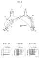
- FIG. 2 is a conceptual diagram illustrating a transmission/reception of image data, sound data, and various types of management information in the transmission system of FIG. 1 .
- FIGs. 3A to 3C are conceptual diagrams explaining the image quality of image data.
- the transmission system 1 illustrated in FIG. 1 includes a plurality of transmission terminals (10aa, 10ab, ...), displays (120aa, 120ab, ...) for the respective transmission terminals (10aa, 10ab, ...), a plurality of administrator terminals (20a, 20b, 20c, and 20d), a plurality of relay devices (30a, 30b, 30c, and 30d), a transmission management system 40, a program providing system 90, and a maintenance system 100. Further, the transmission management system 40 includes a terminal management system 50 and a counterpart registration system 80.
- the plurality of transmission terminals 10 each transmit and receive image data and sound data serving as examples of contents data.
- contents data includes text data.
- contents data it is sufficient for contents data to include at least one of image data, sound data, and text data.
- an arbitrary one or ones of the plurality of transmission terminals (10aa, 10ab, ...) is/are represented as a "transmission terminal(s) 10"
- an arbitrary one or ones of the plurality of displays (120aa, 120ab, ...) is/are represented as a "display(s) 120”
- an arbitrary one or ones of the plurality of relay devices (30a, 30b, 30c, and 30d) is/are represented as a "relay device(s) 30".
- a transmission terminal 10 serving as a request sender that gives a request to start a videoconference is represented as a "starting terminal”
- a transmission terminal 10 serving as a counterpart terminal (relay destination) that is a request destination is represented as a "counterpart terminal”.
- a management information session sei for transmitting and receiving various types of management information is established via the terminal management system 50 between a starting terminal 10A and a counterpart terminal 10B in the transmission system 1.
- four sessions for transmitting and receiving four items of data namely, high-resolution image data (HL), intermediate-resolution image data (ML), low-resolution image data (LL), and sound data (V) are established via a relay device 30 between the starting terminal 10A and the counterpart terminal 10B.
- these four sessions are collectively indicated as an image/sound data session sed. Note that it is not always necessary to have the relay device 30 to relay data between the starting terminal 10A and the counterpart terminal 10B; the image/sound data session sed may be established directly between the starting terminal 10A and the counterpart terminal 10B.
- a low-resolution image serving as a base image, having horizontal 160 pixels by vertical 120 pixels, as illustrated in FIG. 3 A; an intermediate-resolution image having horizontal 320 pixels by vertical 240 pixels, as illustrated in FIG. 3B ; and a high-resolution image having horizontal 640 pixels by vertical 480 pixels, as illustrated in FIG. 3C .
- low-quality image data that only includes low-resolution image data serving as a base image is relayed.
- intermediate-quality image data including low-resolution image data serving as a base image and intermediate-resolution image data is relayed.
- high-quality image data including low-resolution image data serving as a base image, intermediate-resolution image data, and high-resolution image data is relayed.
- the relay devices 30 illustrated in FIG. 1 relay contents data between the plurality of transmission terminals 10.
- the terminal management system 50 centrally manages login authentication from the transmission terminals 10, the communication states of the transmission terminals 10, candidate lists of the transmission terminals 10, and the communication states of the relay devices 30, etc.
- an image of image data may be a moving image or a still image, or may include both thereof.
- a plurality of routers select an optimal path for contents data such as image data and sound data.
- contents data such as image data and sound data.
- an arbitrary one or ones of the routers 70a, 70b, 70c, 70d, 70ab, and 70cd is/are represented as a "router(s) 70".
- the program providing system 90 includes a hard disk (HD) 204 described later.
- the HD 204 stores a transmission terminal program for causing a transmission terminal 10 to realize various functions (or for causing a transmission terminal 10 to function as various elements).
- the transmission terminal program may be transmitted to the transmission terminal 10 to be downloaded onto the transmission terminal 10.
- the HD 204 of the program providing system 90 further stores a relay device program for causing a relay device 30 to realize various functions (or for causing a relay device 30 to function as various elements).
- the relay device program may be transmitted to the relay device 30 to be downloaded onto the relay device 30.
- the HD 204 of the program providing system 90 stores a transmission management program for causing the terminal management system 50 to realize various functions (or for causing the terminal management system 50 to function as various elements). For example, the transmission management program may be transmitted to the terminal management system 50 to be downloaded onto the terminal management system 50.
- the HD 204 of the program providing system 90 stores a counterpart registration program for causing the counterpart registration system 80 to realize various functions (or for causing the counterpart registration system 80 to function as various elements).
- the counterpart registration program may be transmitted to the counterpart registration system 80 to be downloaded onto the counterpart registration system 80.
- the terminal management program and the counterpart registration program may be collectively referred to as a transmission management program.
- the maintenance system 100 is implemented by one or more computers for performing maintenance, management, or conservation of at least one of the transmission terminals 10, the relay devices 30, the terminal management system 50, the counterpart registration system 80, and the program providing system 90.
- the maintenance system 100 remotely performs, via a communication network 2, maintenance, management, or conservation of at least one of the transmission terminals 10, the relay devices 30, the terminal management system 50, the counterpart registration system 80, and the program providing system 90.
- the maintenance system 100 may perform maintenance such as management of the model number, serial number, sales contact, maintenance checkup, or a past history of failures of at least one of the transmission terminals 10, the relay devices 30, the terminal management system 50, the counterpart registration system 80, and the program providing system 90.
- the transmission terminals (10aa, 10ab, 10ac, ...), the relay device 30a, and the router 70a are connected to be communicable with each other by a local area network (LAN) 2a.
- the transmission terminals (10ba, 10bb, 10bc, ...), the relay device 30b, and the router 70b are connected to be communicable with each other by a LAN 2b.
- the LAN 2a and the LAN 2b are connected to be communicable with each other by a dedicated line 2ab including the router 70ab and are provided in a certain area A. For example, assuming that the area A is an office in Tokyo, the LAN 2a is managed in the first sales division, and the LAN 2b is managed in the second sales division.
- transmission terminals (10ca, 10cb, 10cc, ...), the relay device 30c, and the router 70c are connected to be communicable with each other by a LAN 2c.
- the transmission terminals (10da, 10db, 10dc, ...), the relay device 30d, and the router 70d are connected to be communicable with each other by a LAN 2d.
- the LAN 2c and the LAN 2d are connected to be communicable with each other by a dedicated line 2cd including the router 70cd and are provided in a certain area B.
- the area B is an office in Osaka
- the LAN 2c is managed in the first development division
- the LAN 2d is managed in the second development division.
- the area A and the area B are connected to be communicable with each other from the routers (70ab and 70cd), respectively, via the Internet 2i.
- the terminal management system 50, the counterpart registration system 80, and the program providing system 90 are connected to be communicable with the transmission terminals 10 and the relay devices 30 via the Internet 2i.
- the terminal management system 50, the counterpart registration system 80, and the program providing system 90 may be located in the area A or the area B, or may be located in other areas.
- the communication network 2 of this embodiment includes the LAN 2a, the LAN 2b, the dedicated line 2ab, the Internet 2i, the dedicated line 2cd, the LAN 2c, and the LAN 2d.
- the communication network 2 may include not only a wired network, but also a network where communication is performed wirelessly, such as Wireless Fidelity (WiFi) or Bluetooth (registered trademark).
- each of the transmission terminals 10 each of the relay devices 30, the terminal management system 50, each of the routers 70, the counterpart registration system 80, and the program providing system 90 indicates an IP address in an abbreviated form in the general Internet Protocol version 4 (IPv4).
- IPv4 Internet Protocol version 4
- the IP address of the transmission terminal 10aa is "1.2.1.3”.
- IPv6 may be used instead of IPv4
- IPv4 is used in order to make the description simple.
- the transmission terminals 10 may be used not only for communication between offices or between different rooms in the same office, but also for communication within the same room or for outdoor-indoor communication or outdoor-outdoor communication. In the case where the transmission terminals 10 are used outside, wireless communication using a cellular phone communication network or the like is performed.
- FIG. 4 is an external view of the transmission terminal 10.
- the longitudinal direction of the transmission terminal 10 is the X-axis direction
- a direction orthogonal to the X-axis direction on one plane is the Y-axis direction
- a direction orthogonal to the X-axis direction and the Y-axis direction (vertical direction) is the Z-axis direction.
- the transmission terminal 10 includes a casing 1100, an arm 1200, and a camera housing 1300.
- a front wall 1110 of the casing 1100 has an inlet face including a plurality of inlet holes
- a back wall 1120 of the casing 1100 has an exhaust face 1121 on which a plurality of exhaust holes are formed. Accordingly, by driving of a cooling fan included in the casing 1100, air behind the transmission terminal 10 can be taken in via the inlet face and exhausted to the rear of the transmission terminal 10 via the exhaust face 1121.
- a right-side wall 1130 of the casing 1100 has a sound pickup hole 1131 formed thereon, and a built-in microphone 114, described later, is capable of picking up sound and noise.
- An operation panel 1150 is formed toward the right-side wall 1130 of the casing 1100.
- the operation panel 1150 has a plurality of operation keys (108a to 108e), a power switch 109, and an alarm lamp 119, which are formed thereon.
- the operation panel 1150 has a sound output face 1151, which is formed of a plurality of sound output holes for allowing output sound from a built-in a speaker 115 to pass through.
- an accommodation portion 1160 serving as a recess for accommodating the arm 1200 and the camera housing 1300 is formed toward a left-side wall 1140 of the casing 1100.
- a plurality of connection ports (1132a to 1132c) for electrically connecting cables to an external device connection interface (I/F) 118 are provided on the right-side wall 1130 of the casing 1100.
- a connection port for electrically connecting a cable 120c for a display 120 to the external device connection I/F 118 is provided toward the left-side wall 1140 of the casing 1100.
- operation key(s) 108 for indicating an arbitrary one or ones of the operation keys (108a to 108e)
- connection port(s) 1132 for indicating an arbitrary one or ones of the connection ports (1132a to 1132c).
- the arm 1200 is attached to the casing 1100 via a torque hinge 1210 and is rotatable in the vertical direction within the range of a tilt angle ⁇ 1 of 135 degrees with respect to the casing 1100.
- FIG. 4 indicates a state in which the tilt angle ⁇ 1 is 90 degrees.
- the camera housing 1300 has a built-in camera 112 provided thereon, and the camera 112 can capture an image of a user, a document, a room, or the like.
- the camera housing 1300 has a torque hinge 1310 formed thereon.
- the camera housing 1300 is attached to the arm 1200 via the torque hinge 1310 and is rotatable in the vertical and horizontal directions within a range of a pan angle ⁇ 2 of ⁇ 180 degrees and a tilt angle ⁇ 3 of ⁇ 45 degrees with respect to the arm 1200, in which the state illustrated in FIG. 4 serves as 0 degrees.
- the relay devices 30, the terminal management system 50, the counterpart registration system 80, the program providing system 90, and the maintenance system 100 each have the same appearance as that of a general server computer, descriptions of the outer appearances thereof are omitted.
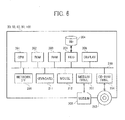
- FIG. 5 is a hardware configuration diagram of the transmission terminal 10.
- the transmission terminal 10 of the embodiment includes a central processing unit (CPU) 101 that controls entire operation of the transmission terminal 10, a read-only memory (ROM) 102 that stores a program used for controlling the CPU 101, such as an initial program loader (IPL), a random-access memory (RAM) 103 used as a work area for the CPU 101, a flash memory 104 that stores various types of data, such as the transmission terminal program, image data, and sound data, a solid state drive (SSD) 105 that controls reading/ writing of various types of data from/to the flash memory 104 under control of the CPU 101, a medium drive 107 that controls reading/writing (storage) of data from/to a recording medium 106 such as a flash memory, the operation keys 108 operated in the case of, for example, selecting a counterpart terminal for the transmission terminal 10, the power switch 109 for turning ON/OFF the power of the transmission terminal 10, and a network interface (I/F) 111 for
- IPL initial
- the transmission terminal 10 includes: the built-in camera 112, which captures an image of a subject and obtains image data under control of the CPU 101; an imaging element I/F 113 that controls driving of the camera 112; the built-in microphone 114, which receives an audio input; the built-in speaker 115, which outputs sound; a sound input/output I/F 116 that processes inputting/outputting of a sound signal between the microphone 114 and the speaker 115 under control of the CPU 101; a display I/F 117 that transmits image data to an external display 120 under control of the CPU 101; the external device connection I/F 118 connected to a connection port 1021 g illustrated in FIG. 4 in order to connect various external devices; the alarm lamp 119, which indicates an abnormality of various functions of the transmission terminal 10; and a bus line 110 such as an address bus and a data bus for electrically connecting the above-described elements as illustrated in FIG. 5 .
- a bus line 110 such as an address bus and a data bus for electrically connecting the above
- the display 120 may be implemented by a liquid crystal display or organic electroluminescence (EL) display, which displays an image of a subject, an operation icon, or the like.
- the display 120 is connected to the display I/F 117 by the cable 120c.
- the cable 120c may be an analog red green blue (RGB) (video graphic array (VGA)) signal cable, a component video cable, a high-definition multimedia interface (HDMI) signal cable, or a digital video interactive (DVI) signal cable.
- RGB red green blue
- VGA video graphic array
- HDMI high-definition multimedia interface
- DVI digital video interactive
- the camera 112 includes a lens system, and a solid-state imaging element that photoelectrically converts an image of a subject to electronic data.
- a solid-state imaging element for example, a complementary metal-oxide-semiconductor (CMOS) or a charge-coupled device (CCD) is used.
- CMOS complementary metal-oxide-semiconductor
- CCD charge-coupled device
- the external device connection I/F 118 is capable of connecting an external device such as an external camera, an external microphone, or an external speaker by using a Universal Serial Bus (USB) cable or the like.
- USB Universal Serial Bus
- the external camera is driven in preference to the built-in camera 112 under control of the CPU 101.
- the external microphone or the external speaker is driven in preference to the built-in microphone 114 or the built-in speaker 115 under control of the CPU 101.
- the camera 112, the microphone 114, and the speaker 115 need not necessarily be included in the transmission terminal 10, and the transmission terminal 10 may be connected to only an external camera, an external microphone, and an external speaker.
- the recording medium 106 is removable from the transmission terminal 10.
- a non-volatile memory that reads or writes data under control of the CPU 101 is not limited to the flash memory 104, and an electrically erasable and programmable read-only memory (EEPROM) may be used instead.
- EEPROM electrically erasable and programmable read-only memory
- the transmission terminal program may be stored in a file in an installable format or an executable format on a computer-readable recording medium such as the recording medium 106 for distribution.
- the transmission terminal program may be stored on the ROM 102, instead of the flash memory 104.
- FIG. 6 is a hardware configuration diagram of any one of the relay device 30, the terminal management system 50, the counterpart registration system 80, the program providing system 90, and the maintenance system 100.
- the terminal management system 50 is described below.
- the terminal management system 50 includes a CPU 201 that controls entire operation of the terminal management system 50, a ROM 202 that stores a program used for controlling the CPU 201, such as an IPL, a RAM 203 used as a work area for the CPU 201, the HD 204 that stores various types of data such as the terminal management program, a hard disk drive (HDD) 205 that controls reading/ writing of various types of data from/to the HD 204 under control of the CPU 201, a medium drive 207 that controls reading/writing (storage) of data from/to a recording medium 206 such as a flash memory, a display 208 that displays various types of information such as a cursor, a menu, a window, characters, or an image, a network I/F 209 for transmitting data using the communication network 2, a keyboard 211 including a plurality of keys for entering characters, numerals, and various instructions, a mouse 212 that selects and executes various instructions, selects a processing target, and moves the cursor, a compact disc
- terminal management program may be stored in a file in an installable format or an executable format on a computer-readable recording medium such as the recording medium 206 or the CD-ROM 213 and distributed.
- terminal management program may be stored on any desired memory such as the ROM 202, instead of the HD 204.
- the relay devices 30 have a hardware configuration that is the same as or similar to that of the above-described terminal management system 50, a description thereof is omitted.
- the HD 204 stores a relay device program for controlling the relay devices 30.
- the relay device program may be stored in a file in an installable format or an executable format on a computer-readable recording medium such as the recording medium 206 or the CD-ROM 213 and distributed.
- the relay device program may be stored on any desired memory such as the ROM 202, instead of the HD 204.
- the counterpart registration system 80 has a hardware configuration that is the same as or similar to that of the above-described terminal management system 50, a description thereof is omitted.
- the HD 204 stores a counterpart registration program for controlling the counterpart registration system 80.
- the counterpart registration program may be stored in a file in an installable format or an executable format on a computer-readable recording medium such as the recording medium 206 or the CD-ROM 213 and distributed.
- the counterpart registration program may be stored on any desired memory such as the ROM 202, instead of the HD 204.
- the program providing system 90 and the maintenance system 100 each have a hardware configuration that is the same as or similar to that of the above-described terminal management system 50, descriptions thereof are omitted.
- the HD 204 stores a program providing program for controlling the program providing system 90.
- the program providing program may be recorded in a file in an installable format or an executable format on a computer-readable recording medium such as the recording medium 206 or the CD-ROM 213 and distributed.
- the program providing program may be stored on any desired memory such as the ROM 202, instead of the HD 204.
- each of the above-described programs may be stored on a computer-readable recording medium such as a compact disc recordable (CD-R), a digital versatile disc (DVD), or a Blue-ray disc, which serve as other examples of the above-described removable recording medium, and may be provided.
- a computer-readable recording medium such as a compact disc recordable (CD-R), a digital versatile disc (DVD), or a Blue-ray disc, which serve as other examples of the above-described removable recording medium, and may be provided.
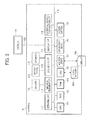
- FIG. 7 is a schematic block diagram illustrating a functional structure of the terminal management system 50 and the counterpart registration system 80 of the transmission management system 40.
- the terminal management system 50 includes a second communicator 51, a second authenticator 52, a memory control 53, and a memory 60.
- the memory control 53 includes a data processor 54, a second extractor 55, a terminal manager 56, and a candidate list manager 57.
- the memory 60 includes a terminal authentication management DB 61, a terminal management DB 62, a candidate list management DB 63, a group management DB 64, and an administrator DB 65.
- data stored in the group management DB 64 and the administrator DB 65 are one example of first association information.
- the data stored in the candidate list management DB 63 is one example of second association information.
- the group management DB 64 is one example of third association information, of the first association information.
- the administrator DB 65 is one example of fourth association information, of the first association information.
- FIG. 8 is a conceptual diagram of the terminal authentication management DB 61.
- the terminal authentication management DB 61 stores a terminal ID and a password in association with each other, as association information.
- the terminal ID is identification information for identifying a transmission terminal 10.
- the terminal ID (an example of terminal identification information) may be identification information previously stored in a memory of the transmission terminal 10, or may be identification information input by the user of the transmission terminal 10 to the transmission terminal 10.
- the password is a password for the transmission terminal 10 to log in to the transmission management system 40 with the terminal ID. Note that records in the terminal authentication management DB 61 may have columns (fields) other than those described above.
- FIG. 9 is a conceptual diagram of the terminal management DB 62.
- the terminal management DB 62 stores a terminal ID, name, operation state, date/time received, and IP address of a terminal as items of association information that are associated with one another.
- the terminal ID is identification information for identifying a transmission terminal 10.
- the name is the name of the transmission terminal 10. Alternatively, the name may be the name of the user of the transmission terminal 10, the name of a department to which the user belongs, or the like.
- the operation state is the most recently obtained operation state of the transmission terminal 10.
- the date/time received is the date and time at which a login request from the transmission terminal 10 to the transmission management system 40 has been accepted.
- the IP address is the IP address of the transmission terminal 10. Note that records in the terminal management DB 62 may have columns other than those described above.
- FIG. 10 is a conceptual diagram of the candidate list management DB 63.
- the candidate list management DB 63 manages the terminal ID of a starting terminal and the terminal ID of a candidate counterpart terminal that may be requested by the starting terminal to have communication with, as items of association information that are associated with each other. Note that records in the candidate list management DB 63 may have columns other than those described above.
- FIG. 11 is a conceptual diagram of the group management DB 64.
- the group management DB 64 stores a group ID, group name, and terminal ID for identifying a transmission terminal belonging to that group, in association with one another, as association information.
- the group ID is an example of identification information for identifying a group.
- the records in the group management DB 64 may have columns (fields) other than those described above.
- FIG. 12 is a conceptual diagram of the administrator DB 65.
- the administrator DB 65 manages an administrator ID, password, and a group ID for identifying a group being managed by the administrator, in association with one another, as association information.
- the table of FIG. 12 indicates that, the administrator A having the administrator ID "02A” manages the group G1 having the group ID "G001" and the group G2 having the group ID "G002".
- the administrator B having the administrator ID "02B” manages the group G3 having the group ID "G003".
- the administrator C having the administrator ID "02C” manages the group G4 having the group ID "G004".
- the records in the administrator DB 65 may have columns (fields) other than those described above.
- the administrator ID is one example of identification information for identifying the administrator of the transmission terminal 10.
- the administrator ID may be replaced by a name of the administrator.
- the password is used for logging into the management system 40 with a specific administrator ID.
- the second communicator 51 communicates with the transmission terminal 10 or the other system, through the communication network 2.
- the second authenticator 52 authenticates a transmission terminal 10, which logs in the terminal management system 50 (transmission management system 40) to start communication with the counterpart transmission terminal 10. More specifically, the second authenticator 52 searches the terminal authentication management DB 61 in the memory 60, using a terminal D and a password included in login information received at the second communicator 51 as search keys. The second authenticator 52 determines whether the search keys match a terminal ID and a password in the terminal authentication management DB 61, to determine whether to allow login to the terminal management system 50.
- the terminal manager 56 manages the operation state of the transmission terminal 10, which requests for logging into the transmission management system 40.
- the terminal manager 56 updates a record in the terminal management DB 62 that corresponds to the terminal ID of the transmission terminal 10, which has given the login request to the terminal management system 50 (the transmission management system 40). Specifically, in the case of successful login, the "operation state" is changed from offline to online (communication OK), and the "date/time received” and the "IP address" are updated.
- the second extractor 55 searches the candidate list management DB 63 by using, for example, the terminal ID of the transmission terminal 10, which has given the login request to the terminal management system 50 (the transmission management system 40), as a search key, and reads a terminal ID registered as a candidate counterpart terminal for the transmission terminal 10, which has given the login request.
- the second extractor 55 searches the terminal management DB 62 by using the extracted terminal ID as a search key, and reads the operation state of a transmission terminal 10 for every extracted terminal ID. The read terminal ID and the operation state are transmitted to the transmission terminal 10, which has given the login request to the transmission management system 40, via the second communicator 51.
- a candidate list including a candidate counterpart terminal(s) is displayed on the display 120 of the transmission terminal 10, which has given the request.
- the user of the transmission terminal 10 selects a desired counterpart terminal from the candidate list, thereby establishing a session sed between the transmission terminals 10 and realizing communication between the transmission terminals 10.
- the session sed between the transmission terminals 10 may be established via the transmission management system 40 or may directly be established.
- the transmission terminals 10 can exchange contents data through the session sed.
- the second extractor 55 can also search the candidate list management DB 63 by using the terminal ID of the transmission terminal 10, which has given the login request to the transmission management system 40, as a search key, and extract the terminal ID of a starting terminal from a record in which the terminal ID of the transmission terminal 10, which has given the login request, is registered as the terminal ID of a candidate counterpart terminal. Accordingly, the second extractor 55 searches the terminal management DB 62 by using, as a search key, the terminal ID of a starting terminal that registers the transmission terminal 10, which has given the login request, as a candidate counterpart terminal, thereby extracting a corresponding operation state.
- the candidate list manager 57 adds, changes, or deletes a record to/in/from the candidate list management DB 63.
- the data processor 54 performs processing to store data in the memory 60. In addition, the data processor 54 performs processing to read data stored in the memory 60.
- the counterpart registration system 80 includes a first communicator 81, a first authenticator 82, and a display control 83. Further, the display control 83 includes a data processor 84, a first extractor 85, a screen data generator 86, and a determiner 87.
- the first communicator 81, the data processor 84, and the first extractor 85 have functions that are the same as or similar to those of the second communicator 51, the data processor 54, and the second extractor 55, respectively, and hence descriptions thereof are omitted.
- the counterpart registration system 80 has no memory in this embodiment, the data processor 84 and the first extractor 85 can realize the same functions as those of the data processor 54 and the second extractor 55 by accessing the memory 60 of the terminal management system 50 via the communication network 2.
- the first authenticator 82 authenticates a transmission terminal 10 or an administrator terminal 20 when the transmission terminal 10 or the administrator terminal 20 tries to log in to the counterpart registration system 80 (transmission management system 40) in order to add or delete a candidate counterpart terminal. Specifically, a request to add or delete a candidate counterpart terminal can be given not only from the transmission terminal 10, but also from the administrator terminal 20.
- the first authenticator 82 searches the terminal authentication management DB 61 (or the administrator DB 65) of the memory 60 by using a terminal ID (or an administrator ID) and a password included in login information received by the first communicator 81 as search keys.
- the first authenticator 82 determines whether the search keys match information in the terminal authentication management DB 61 (or the administrator DB 65), thereby authenticating whether to permit login to the counterpart registration system 80 (transmission management system 40).
- the screen data generator 86 generates various screens, such as an authentication screen (see FIG. 17 ), an administrator registration screen (see FIG.. 18 ), a management terminal list screen (see FIG.. 19 ), a management terminal registration screen (see FIG.. 21 ), and a confirmation screen (see FIG.. 22 and 23 ).
- the screen data generator 86 generates a screen in, for example, HyperText Markup Language (HTML).
- HTML HyperText Markup Language
- the data processor 84 performs operation as described below.
- the terminal ID of the management terminal is one example of identification information for identifying the management terminal.
- the terminal ID of the starting terminal is one example of identification information for identifying the starting terminal.
- the terminal ID of the candidate counterpart terminal is one example of identification information for identifying the candidate counterpart terminal.
- the identification information may include not only the terminal ID, but also the terminal name, and a manufacturing number of the terminal.
- the data processor 84 performs the function of registering a management terminal. For example, in response to a request for registering a specific terminal as a management terminal that is received at the first communicator 81, the data processor 84 stores a terminal ID of the specific terminal, in association with a specific administrator ID, to register the specific terminal as a management terminal to be managed by the administrator identified by the specific administrator ID. More specifically, the first association information associating one or more management terminals and the administrator, which may be managed using the group management DB 64 and the administrator DB 65, is updated to include the specific terminal as the management terminal for the specific administrator that sends the request.
- the data processor 84 further performs the function of registering a candidate counterpart terminal, respectively, for the newly registered management terminal and the previously registered management terminal. For example, the data processor 84 extracts the terminal ID of each of one or more management terminals other than the specific management terminal just registered ("the newly registered management terminal"), from the first association information for the specific administrator. The data processor 84 further registers the terminal ID of the newly registered management terminal, as a candidate counterpart terminal for each one of the other management terminals of the specific administrator, by storing the terminal ID of the newly registered management terminal in association with the extracted terminal ID of each one of the other management terminals, which is a starting terminal ID, in the second association information. For example, the second association information may be managed using the candidate list management DB 63.
- the data processor 84 further associates the extracted terminal ID of each one of the other management terminals, with the terminal ID of the newly registered management terminal, which is a starting terminal ID, in the second association information, to register each one of the other management terminals as a candidate counterpart terminal for the newly registered management terminal.
- the data processor 84 performs the function of deleting a management terminal. For example, in response to a request for deleting a specific management terminal from being under management of the specific administrator, received at the first communicator 81, the data processor 84 deletes a terminal ID of the specific management terminal, which is stored in association with a specific administrator ID of the specific administrator in the first association information, to delete the specific management terminal from the management terminals being managed by the specific administrator.
- the data processor 84 further performs the function of deleting a candidate counterpart terminal, respectively, for the deleted management terminal and the registered management terminal. For example, the data processor 84 extracts the terminal ID of each one or more management terminals other than the specific management terminal being just deleted ("the deleted management terminal"), from the first association information for the specific administrator. The data processor 84 further deletes the terminal ID of the deleted management terminal, which is stored as a candidate counterpart terminal for each one of the other management terminals of the specific administrator, by deleting the terminal ID of the deleted management terminal that is stored in association with the terminal ID of the other management terminal that is a starting terminal ID, in the second association information. The data processor 84 further deletes the terminal ID of the terminal ID of each one of the other management terminals, which is stored as a candidate counterpart terminal for the deleted management terminal that is a starting terminal ID, in the second association information.
- FIGs. 13 and 14 example operation of registering a candidate counterpart terminal to the candidate list is explained.
- FIG. 15 example operation of deleting a candidate counterpart terminal from the candidate list is explained.
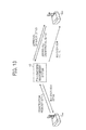
- FIG. 13 is a conceptual diagram illustrating example operation of registering a candidate counterpart terminal, in case of a first scenario.
- this example scenario illustrated in FIG. 13 it is assumed that the user at the transmission terminal 10aa requests to register the transmission terminal 10da, which belongs to a different group, as a candidate counterpart terminal in the candidate list for the terminal 10aa.
- the transmission terminal 10aa sends a request for registering the transmission terminal 10da as a candidate counterpart terminal for the terminal 10aa, to the transmission management system 40.
- the transmission management system 40 sends a request for approval to register the terminal 10da as a candidate counterpart terminal for the terminal 10aa, to the terminal 10da.
- the transmission terminal 10da sends a response indicating whether to approve or disapprove registration, to the transmission management system 40.
- the transmission management system 40 registers the transmission terminal 10da, as a candidate counterpart terminal for the transmission terminal 10aa, in the candidate list management DB 63.
- the transmission management system 40 sends notification indicating completion of registration to the transmission terminal 10aa and the transmission terminal 10da, respectively.
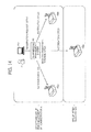
- FIG. 14 is a conceptual diagram illustrating example operation of registering a candidate counterpart terminal, in case of a second scenario.
- the transmission management system 40 when the transmission terminals 10aa and 10ab are already registered as a management terminal of the group G1 being managed by the administrator A, the transmission management system 40 newly registers the transmission terminal 10ac, as a management terminal of the group G1, and further performs the process of registering the newly registered terminal 10ac as a candidate counterpart terminal.
- the administrator terminal 20a sends a request for registering the transmission terminal 10ac, as a management terminal of the group G1 (group ID "G001") being managed by the administrator A, to the transmission management system 40.
- the transmission management system 40 registers the transmission terminal 10ac as a management terminal of the group G1, and performs the process of registering candidate counterpart terminals respectively for the newly registered terminal 10ac and previously registered terminals 10 in the group G1.
- the transmission management system 40 registers the newly registered transmission terminal 10ac, as a candidate counterpart terminal for each one of the terminals 10aa and 10ab of the same group G1, in the candidate list management DB 63.
- the transmission management system 40 registers the transmission terminals 10aa and 10ab, which are already registered, as a candidate counterpart terminal for the newly registered terminal 1 0ac of the same group G1, in the candidate list management DB 63.
- the administrator A or the user of each terminal 10 does not have to instruct registration of the newly registered terminal 10ac as a candidate counterpart terminal or registration of the previously registered terminals 10aa and 10ab as a candidate counterpart terminal.
- registration of candidate counterpart terminals will be automatically performed by the transmission management system 40, collectively, for each one of the terminals in that group.
- the transmission management system 40 sends notification indicating that the transmission terminal 10ac is newly registered to the group G1, respectively, to the transmission terminals 10aa, 10ab, and 10ac.
- the transmission management system 40 further sends notification indicating completion of registration of candidate counterpart terminals, respectively, to the transmission terminals 10aa, 10ab, and 10ac.
- FIG. 15 is a conceptual diagram illustrating example operation of deleting a candidate counterpart terminal, in case of a third scenario.
- the transmission management system 40 deletes the transmission terminal 10ab from the management terminal of the group G1, and further performs the process of deleting a candidate counterpart terminal, respectively, for the deleted transmission terminal 10ab and the registered terminal 10aa.
- the administrator terminal 20a sends a request for deleting the transmission terminal 10ab, which is a management terminal, from the group G1 (group ID "G001") being managed by the administrator A.
- the transmission management system 40 deletes the transmission terminal 10ab from the management terminals of the group G1, and further performs the process of deleting the candidate counterpart terminals, respectively, for the terminal 10aa and 10ab. In this deletion process, the transmission management system 40 deletes the deleted transmission terminal 10ab, from the candidate counterpart terminals for the transmission terminal 10aa of the same group G1. Further, in the deletion process, the transmission management system 40 deletes the transmission terminal 10aa, from the candidate counterpart terminals for the transmission terminal 10ab of the same group G1.
- the administrator A or the user of each terminal 10 does not have to instruct deletion of the deleted transmission terminal 10ab from the candidate counterpart terminals or deletion of the transmission terminal 10aa from the candidate counterpart terminals.
- the deletion process will be automatically performed by the transmission management system 40, collectively, for each one of the terminals in the group.
- the transmission management system 40 sends notification indicating that the transmission terminal 10ab is deleted from the group G1, respectively, to the transmission terminals 10aa and 10ab.
- the transmission management system 40 further sends notification indicating completion of deletion of candidate counterpart terminals, respectively, to the transmission terminals 10aa and 10ab.
- FIG. 16 is a flowchart illustrating operation of managing terminals, performed by the transmission management system 40, according to an example embodiment of the present invention.
- the first authenticator 82 of the counterpart registration system 80 determines whether a login request is received from the administrator terminal 20, which is operated by the administrator, with an administrator ID of the administrator, through the communication network 2. When it is determined that the login request with the administrator ID is received ("YES" at S101), the operation proceeds to S102. When it is determined that the login request with the administrator ID is not received ("NO" at S101), which includes the case where a login request with a user ID is received, the operation proceeds to S199.
- the counterpart registration system 80 performs a login process with the user ID.
- the transmission terminal 10 which logs in with the user ID, can only register a candidate counterpart terminal to its own candidate list prepared for that terminal 10.
- the administrator terminal 20, which logs in with the administrator ID can register a candidate counterpart terminal to candidate lists of management terminals belonging to the group being managed by the administrator.
- FIG. 17 is a conceptual diagram of an authentication screen of the transmission management system 40.
- the screen data generator 86 displays, via the first communicator 81, an authentication screen illustrated by way of example in FIG. 17 on the administrator terminal 20 operated by the administrator.
- the counterpart registration system 80 determines to proceed to S102.
- terminal authentication is selected on the screen of FIG. 17 .
- the counterpart registration system 80 determines to proceed to S 199.
- the screen data illustrated in FIGs. 17, 18 , 19 , and 21 to 23 are stored in a memory of the screen data generator 86.
- these screen data may be stored in the memory 60.
- the data processor 84 may read out any one of the screen data according to an instruction from the screen data generator 86.
- the operation proceeds to S102.
- the first authenticator 82 determines whether administrator information such as the administrator ID and the password, is unregistered in the administrator DB 65. When it is determined that the administrator information is registered in the administrator DB 65 ("NO" at S102), at S104, the first authenticator 82 permits login. When it is determines that the administrator information is not registered, that is, unregistered ("YES" at S102), the operation proceeds to S103.
- the screen data generator 86 displays, via the first communicator 81, a registration screen on the administrator terminal 20 operated by the administrator.
- the counterpart registration system 80 logs in the administrator.
- An example of the case in which administrator information is unregistered in the administrator DB 65 is, for example, the case in which the administrator is registered for the first time using an initial setting password.
- FIG. 18 is a conceptual diagram of an administrator registration screen.
- the administrator registration screen illustrated in FIG. 18 is displayed on the administrator terminal 20.
- the screen data generator 86 generates a management terminal list screen illustrated in FIG. 19 , and the first communicator 81 transmits data of the management terminal list screen to the administrator terminal 20, thereby displaying the screen.
- FIG. 19 is a conceptual diagram of the management terminal list screen.
- the management terminal list screen includes a list of transmission terminals 10 managed by the administrator who logs in.
- the first extractor 85 searches the administrator DB 65 using the administrator ID received at the counterpart registration system 80 as a search key to obtain the group ID associated with the administrator ID.
- the first extractor 85 searches the group management DB 64 using the obtained group ID as a search key to obtain the group name and the management terminal ID, which are respectively associated with the group ID.
- the first extractor 85 searches the candidate list management DB 63 using the obtained management terminal ID, which corresponds to the starting terminal ID, as a search key to obtain a terminal ID of each one of candidate counterpart terminals for the starting terminal ID.
- the screen data generator 86 Based on this information obtained at the first extractor 85, the screen data generator 86 generates the management terminal list screen.
- the management terminal list screen which is generated as described above, displays the name and the terminal ID of the management terminal that are obtained from the terminal management DB 62, and the terminal IDs of the candidate counterpart terminals associated with the starting terminal ID obtained from the candidate list management DB 63 (that is the same as the terminal ID in the terminal management DB 62), in association with one another.
- the management terminal list screen further displays the "Delete" key for each management terminal ID. When the "Delete" key is selected, a request for deleting the terminal 10 indicated by the corresponding terminal ID from the management terminals is accepted.
- the screen of FIG. 19 indicates that the administrator A manages a plurality of groups including the group G 1 (first sales division) and the group G2 (second sales division). Further, as management terminals of the group G1 (first sales division), the transmission terminal 10aa with the name "AA terminal”, and the transmission terminal 10ab with the name "AB terminal” are managed.
- the management terminal list screen further includes the "Register management terminal” key and the "Delete terminals by group” key.
- the "Register management terminal” key when selected, accepts a request for newly registering a transmission terminal 10 as a management terminal.
- the "Delete terminals by group” key when selected, accepts a request for deleting the management terminals 10 that are registered in the group. More specifically, the "Delete terminals by group” key is selected, when requesting to delete all transmission terminals 10 belonging to the group being displayed as a corresponding index is currently selected.
- the "Delete” key which is displayed for each management terminal, is selected when requesting to delete a specific corresponding terminal 10 from the group.
- the management terminal list screen further displays the "Log out” key, which, when selected, requests to log out. These keys may be selected by the administrator, for example, through pressing the key with any desired input device or a finger.
- the counterpart registration system 80 performs the management terminal registration and deletion process, which will be described later.
- the determiner 86 determines whether a request for ending operation is received, for example, by determining whether the "Log out" key is selected by the administrator. When it is determined that the request for ending operation is received ("YES" at S107), the operation proceeds to S108. At S108, the counterpart registration system 40 logs out the administrator terminal 20. When it is determined that the request for ending operation is not received ("NO" at S107), the operation returns to S106.
- FIG. 20 is a flowchart illustrating operation of registering or deleting a management terminal, performed by the counterpart registration system 80.
- FIG. 21 is a conceptual diagram illustrating a management terminal registration screen.
- FIGs. 22 and 23 are each a conceptual diagram illustrating a confirmation screen, which confirms deletion of a management terminal.
- the determiner 87 determines whether to register a management terminal, based on determination of whether the "Register management terminal" key is selected by the administrator. When the "Register management terminal" key is selected ("YES" at S201), the determiner 87 determines to register a management terminal, and the operation proceeds to S202.
- the screen data generator 86 sends a management terminal registration screen, such as the screen illustrated in FIG. 21 , to the administrator 20 through the first communicator 81.
- the administrator terminal 20 displays the management terminal registration screen of FIG. 21 .
- the management terminal registration screen includes a pull-down menu, which allows the administrator to select a group to which a management terminal is to be registered, from a list of groups.
- the management terminal registration screen further includes a plurality of entry fields ("registration terminal ID"), for allowing the administrator to input a terminal ID of the terminal 10 that the administrator wants to register to the selected group.
- registration terminal ID Assuming that the administrator selects the group from the pull-down menu, inputs the terminal ID of the terminal 10 in the "registration terminal ID" entry field, and selects the "Register” key, the administrator terminal 20 sends a registration request to the counterpart registration system 80.
- the registration request includes the group ID of the selected group, the terminal ID entered in the entry field, and the administrator ID of the administrator who logs in.
- the counterpart registration system 80 receives the registration request at the communicator 81.
- the data processor 84 refers to the group management DB 64 of the terminal management system 50, to specify a record including the group ID of the group selected using the management terminal registration screen of FIG. 21 , and adds the terminal ID that is input through the management terminal registration screen of FIG. 21 in a "management terminal ID" column in the specified record. In this manner, the transmission terminal 10 is newly registered as a management terminal for management by the administrator.
- the data processor 84 registers the newly registered management terminal, as a candidate counterpart terminal for the transmission terminal 10 of the same group.
- the data processor 84 further registers the transmission terminal 10 of the same group, as a candidate counterpart terminal for the newly registered management terminal.
- the data processor 84 refers to the candidate list management DB 63 of the terminal management system 50 to specify a record including the terminal ID of the terminal 10 that is already registered in the selected group, as a starting terminal ID, and adds the terminal ID of the newly registered management terminal in a candidate counterpart terminal ID column of the specified record.
- the data processor 84 further refers to the candidate list management DB 63 of the terminal management system 50 to specify a record including the terminal ID of the newly registered management terminal, which is input, as a starting terminal ID, and adds the terminal ID of the terminal 10 of the same group in a candidate counterpart terminal ID column of the specified record.
- the determiner 87 of the counterpart registration system 80 determines whether terminals in the selected group is deleted, that is, the "Delete terminals by group” key is selected. When it is determined the group is to be deleted ("YES" at S205), the operation proceeds to S206.
- the data processor 84 obtains the group ID of the group that is displayed as an index of the screen, and the administrator ID obtained at S 101, and deletes the obtained group ID that is associated with the obtained administrator ID from the administrator DB 65. For example, referring to the management terminal list screen of FIG. 19 where the "First sales division" is selected, it is assumed that the "Delete terminals by group” key is selected. In such case, the group ID "G001" is deleted in the administrator DB 65, specifically, from the "group ID” field associated with the administrator ID of the administrator who logs in.
- the screen data generator 86 may send data of a confirmation screen of FIG. 22 , to the administrator terminal 20 operated by the login administrator, via the first communicator 81.
- the confirmation screen of FIG. 22 confirms the administrator whether to delete the selected group.
- the data processor 84 performs S206 of deleting the group.
- the data processor 84 ends operation of FIG. 20 without performing S206.
- the data processor 84 deletes the terminals used to be in the group that is deleted, from the candidate list for the terminals in the group that is deleted. More specifically, the data processor 84 refers to the candidate list management DB 63 of FIG. 10 , to specify a record including the terminal ID of the terminal 10 that is registered in the deleted group, as a starting terminal ID. The data processor 84 deletes the terminal ID of the terminal 10 that is registered in the deleted group, from the candidate counterpart terminals for the terminal 10 that is registered in the deleted group. For example, as illustrated in Fig. 19 , it is assumed that the "Delete terminals by group" key is selected in a state in which the "first sales division" index has been selected on the management terminal list screen.
- the terminal ID "01ab” of the terminal 10ab similarly included in the deleted group "first sales division” is deleted from the terminal ID of a candidate counterpart terminal associated with the terminal ID "01aa” of the transmission terminal 10aa.
- the terminal ID "01aa” of the terminal 10aa similarly included in the deleted group "first sales division” is deleted from the terminal ID of a candidate counterpart terminal associated with the terminal ID "01ab” of the transmission terminal 10ab.
- a record of the terminal in the group to be deleted that is stored as a starting terminal ID in the candidate list management DB 63, is not deleted.
- the terminal ID of the terminal 10 in the group is deleted from candidate counterpart terminal IDs for that record.
- the data processor 84 obtains the terminal ID of the terminal 10 corresponding to the selected "Delete" key, and the group ID associated with the administrator ID obtained at S101 in the administrator DB 65. From the group management DB of FIG. 11 , the data processor 84 deletes the terminal ID of the selected management terminal, associated with the obtained group ID.
- the data processor 84 deletes the terminal ID "01ab" of the selected terminal, from the management terminal IDs associated with the group ID "G001" of the selected group.
- the screen data generator 86 may send confirmation screen data of FIG. 23 , to the administrator terminal 20 of the administrator who logs in, through the first communicator 81.
- the confirmation screen of FIG. 23 confirms whether to delete the selected management terminal.
- the data processor 84 performs S208.
- the data processor 84 ends without performing S208.
- the data processor 84 refers to a record for the management terminal that is deleted at S208, which is the starting terminal, in the candidate list management DB 63.
- the data processor 84 deletes, from candidate counterpart terminal IDs that are associated with the deleted terminal, that is the starting terminal, the terminal IDs of one or more other terminals belonging to the same group to which the deleted terminal used to belong.
- the data processor 84 further deletes, for a record corresponding to each one of the one or more other terminals of the same group, that is, the starting terminal, the terminal ID of the deleted terminal, from the candidate counterpart terminal IDs associated with the other terminal of the same group.
- the data processor 84 refers to the candidate list management DB 63 to refer to a record for the terminal 10ab, that is, the starting terminal, and deletes the terminal ID "01aa” of the other terminal 10aa in the same group from candidate counterpart terminals 10 associated with the terminal ID "01aa”.
- the data processor 84 refers to a record for the other terminal 10aa of the same group in the candidate list management DB 63 ( FIG. 10 ), that is the starting terminal, and deletes the terminal ID "01ab” of the terminal 10ab from candidate counterpart terminal IDs associated with the terminal ID "01 aa” of the other terminal 10aa in the same group.
- the transmission management system 40 in response to receiving a request for registering a transmission terminal in a group being managed by an administrator, from an administrator terminal operated by the administrator, the transmission management system 40 not only registers the terminal to that group, but also registers that terminal to a list of candidate counterpart terminals for the other terminals that have been registered to that group. The transmission management system 40 further registers the other terminals that are previously registered in that group, as a candidate counterpart terminal of that newly registered terminal.
- the administrator needs to only instruct to register a terminal to be under management by the administrator, such that further operation of registering the terminal to a candidate list management DB 63 is not needed. Further, the transmission management system 40 automatically registers the terminal to the candidate list management DB 63, only for the group being managed by the administrator, thus improving security.
- the transmission management system 40 in response to receiving a request for deleting a transmission terminal from a group being managed by an administrator, from an administrator terminal operated by the administrator, not only deletes the terminal from that group, but also deletes that terminal from a list of candidate counterpart terminals for the other terminals that have been registered to that group. The transmission management system 40 further deletes the other transmission terminals, from a list of candidate counterpart terminals for that terminal to be deleted.
- the administrator needs to only instruct to delete a terminal from a group under management by the administrator, such that further operation of deleting the terminal from a candidate list management DB 63 is not needed. Further, the transmission management system 40 automatically deletes the terminal from the candidate list management DB 63, only for the group being managed by the administrator, thus improving security.
- the transmission management system 40 in response to receiving a request for deleting a group being managed by an administrator, from an administrator terminal operated by the administrator, the transmission management system 40 not only deletes that group from groups being managed by the administrator, but also deletes transmission terminals from a list of candidate counterpart terminals for the transmission terminals that have been registered to that group to be deleted.
- the administrator needs to only instruct to delete a group from the groups under management by the administrator, such that further operation of deleting the terminal from the candidate list management DB 63 is not needed. Further, the transmission management system 40 automatically deletes the terminal from the candidate list management DB 63, only for the group being managed by the administrator, thus improving security.
- the transmission management system 40 is applicable to an arbitrary system as long as the system is a communication system in which transmission terminals 10 are capable of communicating with each other.
- the transmission management system 40 is applicable to a teleconference system, a video conference system, a sound conference system, a sound phone system (including a mobile phone system), a text chat system, or a white-board sharing system.
- transmission terminals 10 may be dedicated terminals for the above-described communication system or game-dedicated terminals, or may be general terminals such as personal computers, smart phones, mobile phone terminals, or tablet terminals.
- the terminal management system 50 and the counterpart registration system 80 it is sufficient for the terminal management system 50 and the counterpart registration system 80 to be information processing apparatuses including the functional blocks illustrated by way of example in FIG. 7 , and the terminal management system 50 and the counterpart registration system 80 maybe dedicated server apparatuses or general terminal apparatuses.
- any of the above-described devices or units can be implemented as a hardware apparatus, such as a special-purpose circuit or device, or as a hardware/software combination, such as a processor executing a software program.
- the present invention can be implemented in any convenient form, for example using dedicated hardware, or a mixture of dedicated hardware and software.
- the present invention may be implemented as computer software implemented by one or more networked processing apparatuses.
- the network can comprise any conventional terrestrial or wireless communications network, such as the Internet.
- the processing apparatuses can compromise any suitably programmed apparatuses such as a general purpose computer, personal digital assistant, mobile telephone (such as a WAP or 3G-compliant phone) and so on. Since the present invention can be implemented as software, each and every aspect of the present invention thus encompasses computer software implementable on a programmable device.
- the computer software can be provided to the programmable device using any conventional carrier medium.
- the carrier medium can compromise a transient carrier medium such as an electrical, optical, microwave, acoustic or radio frequency signal carrying the computer code.
- a transient carrier medium such as an electrical, optical, microwave, acoustic or radio frequency signal carrying the computer code.
- An example of such a transient medium is a TCP/IP signal carrying computer code over an IP network, such as the Internet.
- the carrier medium can also comprise a storage medium for storing processor readable code such as a floppy disk, hard disk, CD ROM, magnetic tape device or solid state memory device.
- the hardware platform includes any desired kind of hardware resources including, for example, a central processing unit (CPU), a random access memory (RAM), and a hard disk drive (HDD).
- the CPU may be implemented by any desired kind of any desired number of processor.
- the RAM may be implemented by any desired kind of volatile or non-volatile memory.
- the HDD may be implemented by any desired kind of non-volatile memory capable of storing a large amount of data.
- the hardware resources may additionally include an input device, an output device, or a network device, depending on the type of the apparatus. Alternatively, the HDD may be provided outside of the apparatus as long as the HDD is accessible.
- the CPU such as a cache memory of the CPU
- the RAM may function as a physical memory or a primary memory of the apparatus, while the HDD may function as a secondary memory of the apparatus.
Landscapes
- Engineering & Computer Science (AREA)
- Signal Processing (AREA)
- Multimedia (AREA)
- Computer Networks & Wireless Communication (AREA)
- General Engineering & Computer Science (AREA)
- Telephonic Communication Services (AREA)
- Two-Way Televisions, Distribution Of Moving Picture Or The Like (AREA)
- Mobile Radio Communication Systems (AREA)
Abstract
Description
- The present invention generally relates to managing candidate counterpart terminals.
- Communication systems that allow communication among a remotely located sites via a communication network such as the Internet have become popular. An example of such a communication system includes a videoconference system. For example, a terminal used by one of two parties that are holding a videoconference converts an image and sound of a subject in a conference room to digital data and transmits the digital data to a terminal used by the other party. The terminal used by the other party displays an image on a display and outputs sound from a speaker. Accordingly, a videoconference between remotely located sites can be held in a state that is similar to an actual conference.
- In such a conference system, technology that registers a candidate counterpart terminal in a candidate list is available. Using the candidate list, a user at a terminal can easily call a terminal that serves as a candidate counterpart terminal to start communication.
- On the other hand, many terminals are used in a large organization such as a company. In such environment, there is an administrator who manages terminals of users. Sometimes, the administrator may want to dispose of an old terminal being managed by the administrator, for example, to replace it with a new terminal. Even after the terminal is disposed of, that terminal continues to be registered as a candidate counterpart terminal of the other terminals that are under management of the administrator. Thus, every time the terminal is removed from the terminals being managed by the administrator, the administrator deletes that terminal not managed by the administrator, from the candidate counterpart terminal for the other terminals being managed by the administrator.
- In view of the above, in one aspect of the present invention, in response to a request for deleting a specific management terminal from being under management of a specific administrator, a transmission management system not only deletes terminal identification information of the specific management terminal, from terminal identification information of management terminals being managed by the specific administrator, but also deletes the terminal identification information of the specific management terminal from candidate counterpart terminal identification information for the other management terminals being managed by the specific administrator.
- For example, example embodiments of the present invention include a transmission management system for managing a plurality of transmission terminals, including: a memory that stores: first association information that associates administrator identification information for identifying an administrator with management terminal identification information for identifying one or more management terminals being managed by the administrator; and second association information that associates, for each one of the plurality of transmission terminals, terminal identification information for identifying a terminal with candidate counterpart terminal identification information for identifying one or more candidate counterpart terminals, to indicate that the terminal is capable of requesting to start communication with the candidate counterpart terminals; a receiver that receives a request for deleting a specific management terminal from being under management of a specific administrator, the request including specific terminal identification information of the specific terminal to be deleted and specific administrator identification information of the specific administrator; and a data processor that deletes the specific terminal identification information from the management terminal identification information being associated with the specific administrator identification information by the first association information. The data processor further specifies one or more management terminals being managed by the specific administrator other than the specific terminal being deleted using the first association information, and deletes the specific terminal identification information of the specific terminal being deleted, from candidate counterpart terminal identification information associated with each one of the other management terminals by the second association information.
- Accordingly, in one aspect of the present invention, the candidate counterpart terminal information is automatically modified to reflect the terminal that is deleted from being under management by an administrator, thus increasing operability for the user.
- A more complete appreciation of the disclosure and many of the attendant advantages and features thereof can be readily obtained and understood from the following detailed description with reference to the accompanying drawings, wherein:
-
FIG. 1 is a schematic diagram illustrating a configuration of a transmission system according to an example embodiment of the present invention; -
FIG. 2 is an illustration for explaining various data such as image data, sound data, and various management information, transmitted or received in the transmission system ofFIG. 1 , according to an example embodiment of the present invention; -
FIGs. 3A to 3C are an illustration for explaining quality of image data; -
FIG. 4 is an external view of a transmission terminal of the transmission system ofFIG. 1 ; -
FIG. 5 is a hardware configuration diagram of the transmission terminal ofFIG. 4 ; -
FIG. 6 is a hardware configuration diagram of a relay device, a terminal management system, a counterpart registration system, a program providing system, and a maintenance system of the transmission system ofFIG. 1 ; -
FIG. 7 is a functional block diagram of the terminal management system and the counterpart registration system included in the transmission management system ofFIG. 1 ; -
FIG. 8 is a conceptual diagram of a terminal authentication management database (DB); -
FIG. 9 is a conceptual diagram of a terminal management DB; -
FIG. 10 is a conceptual diagram of a candidate list management DB; -
FIG. 11 is a conceptual diagram of a group management DB; -
FIG. 12 is a conceptual diagram of an administrator management DB; -
FIG. 13 is a conceptual diagram illustrating an example of a candidate counterpart terminal registration process; -
FIG. 14 is a conceptual diagram illustrating an example of a candidate counterpart terminal registration process; -
FIG. 15 is a conceptual diagram illustrating an example of a candidate counterpart terminal deletion process; -
FIG. 16 is a flowchart illustrating operation of managing a terminal, performed by the transmission management system ofFIG. 1 , according to an example embodiment of the present invention; -
FIG. 17 is an illustration of an example authentication screen; -
FIG. 18 is an illustration of an example administrator registration screen; -
FIG. 19 is an illustration of an example management terminal list screen; -
FIG. 20 is a flowchart illustrating operation of registering or deleting a management terminal, performed by the transmission management system ofFIG. 1 , according to an example embodiment of the present invention; -
FIG. 21 is an illustration of an example management terminal registration screen; -
FIG. 22 is an illustration of an example confirmation screen for management terminal deletion; and -
FIG. 23 is an illustration of an example confirmation screen for management terminal deletion. - The accompanying drawings are intended to depict example embodiments of the present invention and should not be interpreted to limit the scope thereof. The accompanying drawings are not to be considered as drawn to scale unless explicitly noted.
- The terminology used herein is for the purpose of describing particular embodiments only and is not intended to be limiting of the present invention. As used herein, the singular forms "a", "an" and "the" are intended to include the plural forms as well, unless the context clearly indicates otherwise. It will be further understood that the terms "includes" and/or "including", when used in this specification, specify the presence of stated features, integers, steps, operations, elements, and/or components, but do not preclude the presence or addition of one or more other features, integers, steps, operations, elements, components, and/or groups thereof.
- In describing example embodiments shown in the drawings, specific terminology is employed for the sake of clarity. However, the present disclosure is not intended to be limited to the specific terminology so selected and it is to be understood that each specific element includes all technical equivalents that operate in a similar manner.
- In the following description, illustrative embodiments will be described with reference to acts and symbolic representations of operations (e.g., in the form of flowcharts) that may be implemented as program modules or functional processes including routines, programs, objects, components, data structures, etc., that perform particular tasks or implement particular abstract data types and may be implemented using existing hardware at existing network elements or control nodes. Such existing hardware may include one or more Central Processing Units (CPUs), digital signal processors (DSPs), application-specific-integrated-circuits, field programmable gate arrays (FPGAs) computers or the like. These terms in general may be referred to as processors.
- Unless specifically stated otherwise, or as is apparent from the discussion, terms such as "processing" or "computing" or "calculating" or "determining" or "displaying" or the like, refer to the action and processes of a computer system, or similar electronic computing device, that manipulates and transforms data represented as physical, electronic quantities within the computer system's registers and memories into other data similarly represented as physical quantities within the computer system memories or registers or other such information storage, transmission or display devices.
- Referring to the drawings, a
transmission system 1 is explained according to an example embodiment of the present invention. - The
transmission system 1 includes a communication system that intercommunicates information or information reflecting feelings, for example, between or among terminals. In this example, the communication system is a system for intercommunicating information or information reflecting feelings, for example, between or among a plurality of communication terminals (one example of "transmission terminals") via a communication management system (one example of a "transmission management system"), and an example thereof includes a videoconference or teleconference system. -
FIG. 1 is a schematic block diagram illustrating a configuration of thetransmission system 1.FIG. 2 is a conceptual diagram illustrating a transmission/reception of image data, sound data, and various types of management information in the transmission system ofFIG. 1 .FIGs. 3A to 3C are conceptual diagrams explaining the image quality of image data. - The
transmission system 1 illustrated inFIG. 1 includes a plurality of transmission terminals (10aa, 10ab, ...), displays (120aa, 120ab, ...) for the respective transmission terminals (10aa, 10ab, ...), a plurality of administrator terminals (20a, 20b, 20c, and 20d), a plurality of relay devices (30a, 30b, 30c, and 30d), atransmission management system 40, aprogram providing system 90, and amaintenance system 100. Further, thetransmission management system 40 includes aterminal management system 50 and acounterpart registration system 80. - The plurality of
transmission terminals 10 each transmit and receive image data and sound data serving as examples of contents data. Note that another example of contents data includes text data. In other words, it is sufficient for contents data to include at least one of image data, sound data, and text data. - Hereinafter, an arbitrary one or ones of the plurality of transmission terminals (10aa, 10ab, ...) is/are represented as a "transmission terminal(s) 10", an arbitrary one or ones of the plurality of displays (120aa, 120ab, ...) is/are represented as a "display(s) 120", and an arbitrary one or ones of the plurality of relay devices (30a, 30b, 30c, and 30d) is/are represented as a "relay device(s) 30".
- In this example, a
transmission terminal 10 serving as a request sender that gives a request to start a videoconference is represented as a "starting terminal", and atransmission terminal 10 serving as a counterpart terminal (relay destination) that is a request destination is represented as a "counterpart terminal". - As illustrated in
FIG. 2 , a management information session sei for transmitting and receiving various types of management information is established via theterminal management system 50 between a starting terminal 10A and acounterpart terminal 10B in thetransmission system 1. In addition, four sessions for transmitting and receiving four items of data, namely, high-resolution image data (HL), intermediate-resolution image data (ML), low-resolution image data (LL), and sound data (V), are established via arelay device 30 between the starting terminal 10A and thecounterpart terminal 10B. Here, these four sessions are collectively indicated as an image/sound data session sed. Note that it is not always necessary to have therelay device 30 to relay data between the starting terminal 10A and thecounterpart terminal 10B; the image/sound data session sed may be established directly between the starting terminal 10A and thecounterpart terminal 10B. - Here, the resolution of images of image data handled in the embodiment will be described. There are the following images: a low-resolution image, serving as a base image, having horizontal 160 pixels by vertical 120 pixels, as illustrated in
FIG. 3 A; an intermediate-resolution image having horizontal 320 pixels by vertical 240 pixels, as illustrated inFIG. 3B ; and a high-resolution image having horizontal 640 pixels by vertical 480 pixels, as illustrated inFIG. 3C . In the case of communicating via a narrow band, low-quality image data that only includes low-resolution image data serving as a base image is relayed. In the case of communicating via a relatively wide band, intermediate-quality image data including low-resolution image data serving as a base image and intermediate-resolution image data is relayed. In the case of communicating via a very wide band, high-quality image data including low-resolution image data serving as a base image, intermediate-resolution image data, and high-resolution image data is relayed. - The
relay devices 30 illustrated inFIG. 1 relay contents data between the plurality oftransmission terminals 10. Theterminal management system 50 centrally manages login authentication from thetransmission terminals 10, the communication states of thetransmission terminals 10, candidate lists of thetransmission terminals 10, and the communication states of therelay devices 30, etc. Note that an image of image data may be a moving image or a still image, or may include both thereof. - A plurality of routers (70a, 70b, 70c, 70d, 70ab, and 70cd) select an optimal path for contents data such as image data and sound data. Hereinafter, an arbitrary one or ones of the routers (70a, 70b, 70c, 70d, 70ab, and 70cd) is/are represented as a "router(s) 70".
- The
program providing system 90 includes a hard disk (HD) 204 described later. TheHD 204 stores a transmission terminal program for causing atransmission terminal 10 to realize various functions (or for causing atransmission terminal 10 to function as various elements). For example, the transmission terminal program may be transmitted to thetransmission terminal 10 to be downloaded onto thetransmission terminal 10. TheHD 204 of theprogram providing system 90 further stores a relay device program for causing arelay device 30 to realize various functions (or for causing arelay device 30 to function as various elements). For example, the relay device program may be transmitted to therelay device 30 to be downloaded onto therelay device 30. - Further, the
HD 204 of theprogram providing system 90 stores a transmission management program for causing theterminal management system 50 to realize various functions (or for causing theterminal management system 50 to function as various elements). For example, the transmission management program may be transmitted to theterminal management system 50 to be downloaded onto theterminal management system 50. In addition, theHD 204 of theprogram providing system 90 stores a counterpart registration program for causing thecounterpart registration system 80 to realize various functions (or for causing thecounterpart registration system 80 to function as various elements). For example, the counterpart registration program may be transmitted to thecounterpart registration system 80 to be downloaded onto thecounterpart registration system 80. Note that the terminal management program and the counterpart registration program may be collectively referred to as a transmission management program. - In this example, the
maintenance system 100 is implemented by one or more computers for performing maintenance, management, or conservation of at least one of thetransmission terminals 10, therelay devices 30, theterminal management system 50, thecounterpart registration system 80, and theprogram providing system 90. For example, in the case where themaintenance system 100 is located in one country, and thetransmission terminals 10, therelay devices 30, theterminal management system 50, thecounterpart registration system 80, or theprogram providing system 90 is/are located outside that country, themaintenance system 100 remotely performs, via acommunication network 2, maintenance, management, or conservation of at least one of thetransmission terminals 10, therelay devices 30, theterminal management system 50, thecounterpart registration system 80, and theprogram providing system 90. Themaintenance system 100 may perform maintenance such as management of the model number, serial number, sales contact, maintenance checkup, or a past history of failures of at least one of thetransmission terminals 10, therelay devices 30, theterminal management system 50, thecounterpart registration system 80, and theprogram providing system 90. - In this example, the transmission terminals (10aa, 10ab, 10ac, ...), the
relay device 30a, and therouter 70a are connected to be communicable with each other by a local area network (LAN) 2a. The transmission terminals (10ba, 10bb, 10bc, ...), therelay device 30b, and therouter 70b are connected to be communicable with each other by aLAN 2b. In addition, theLAN 2a and theLAN 2b are connected to be communicable with each other by a dedicated line 2ab including the router 70ab and are provided in a certain area A. For example, assuming that the area A is an office in Tokyo, theLAN 2a is managed in the first sales division, and theLAN 2b is managed in the second sales division. - Further, in this example, transmission terminals (10ca, 10cb, 10cc, ...), the
relay device 30c, and therouter 70c are connected to be communicable with each other by aLAN 2c. The transmission terminals (10da, 10db, 10dc, ...), therelay device 30d, and therouter 70d are connected to be communicable with each other by aLAN 2d. In addition, theLAN 2c and theLAN 2d are connected to be communicable with each other by a dedicated line 2cd including the router 70cd and are provided in a certain area B. For example, assuming that the area B is an office in Osaka, theLAN 2c is managed in the first development division, and theLAN 2d is managed in the second development division. The area A and the area B are connected to be communicable with each other from the routers (70ab and 70cd), respectively, via the Internet 2i. - The
terminal management system 50, thecounterpart registration system 80, and theprogram providing system 90 are connected to be communicable with thetransmission terminals 10 and therelay devices 30 via the Internet 2i. Theterminal management system 50, thecounterpart registration system 80, and theprogram providing system 90 may be located in the area A or the area B, or may be located in other areas. - The
communication network 2 of this embodiment includes theLAN 2a, theLAN 2b, the dedicated line 2ab, the Internet 2i, the dedicated line 2cd, theLAN 2c, and theLAN 2d. Thecommunication network 2 may include not only a wired network, but also a network where communication is performed wirelessly, such as Wireless Fidelity (WiFi) or Bluetooth (registered trademark). - In
FIG. 1 , four digits indicated below each of thetransmission terminals 10, each of therelay devices 30, theterminal management system 50, each of the routers 70, thecounterpart registration system 80, and theprogram providing system 90 indicates an IP address in an abbreviated form in the general Internet Protocol version 4 (IPv4). For example, the IP address of the transmission terminal 10aa is "1.2.1.3". Although IPv6 may be used instead of IPv4, IPv4 is used in order to make the description simple. - Note that the
transmission terminals 10 may be used not only for communication between offices or between different rooms in the same office, but also for communication within the same room or for outdoor-indoor communication or outdoor-outdoor communication. In the case where thetransmission terminals 10 are used outside, wireless communication using a cellular phone communication network or the like is performed. - Next, referring to
FIGs. 4 to 6 , the hardware configuration of thetransmission system 1 of this embodiment will be described.FIG. 4 is an external view of thetransmission terminal 10. The description will be given assuming that the longitudinal direction of thetransmission terminal 10 is the X-axis direction, a direction orthogonal to the X-axis direction on one plane is the Y-axis direction, and a direction orthogonal to the X-axis direction and the Y-axis direction (vertical direction) is the Z-axis direction. - As illustrated in
FIG. 4 , thetransmission terminal 10 includes acasing 1100, anarm 1200, and acamera housing 1300. Among these portions, afront wall 1110 of thecasing 1100 has an inlet face including a plurality of inlet holes, and aback wall 1120 of thecasing 1100 has anexhaust face 1121 on which a plurality of exhaust holes are formed. Accordingly, by driving of a cooling fan included in thecasing 1100, air behind thetransmission terminal 10 can be taken in via the inlet face and exhausted to the rear of thetransmission terminal 10 via theexhaust face 1121. A right-side wall 1130 of thecasing 1100 has asound pickup hole 1131 formed thereon, and a built-inmicrophone 114, described later, is capable of picking up sound and noise. - An
operation panel 1150 is formed toward the right-side wall 1130 of thecasing 1100. Theoperation panel 1150 has a plurality of operation keys (108a to 108e), apower switch 109, and analarm lamp 119, which are formed thereon. In addition, theoperation panel 1150 has asound output face 1151, which is formed of a plurality of sound output holes for allowing output sound from a built-in aspeaker 115 to pass through. In addition, anaccommodation portion 1160 serving as a recess for accommodating thearm 1200 and thecamera housing 1300 is formed toward a left-side wall 1140 of thecasing 1100. A plurality of connection ports (1132a to 1132c) for electrically connecting cables to an external device connection interface (I/F) 118 are provided on the right-side wall 1130 of thecasing 1100. A connection port for electrically connecting acable 120c for adisplay 120 to the external device connection I/F 118 is provided toward the left-side wall 1140 of thecasing 1100. - The following description uses the term "operation key(s) 108" for indicating an arbitrary one or ones of the operation keys (108a to 108e), and the term "connection port(s) 1132" for indicating an arbitrary one or ones of the connection ports (1132a to 1132c).
- The
arm 1200 is attached to thecasing 1100 via atorque hinge 1210 and is rotatable in the vertical direction within the range of a tilt angle θ1 of 135 degrees with respect to thecasing 1100.FIG. 4 indicates a state in which the tilt angle θ1 is 90 degrees. - The
camera housing 1300 has a built-incamera 112 provided thereon, and thecamera 112 can capture an image of a user, a document, a room, or the like. In addition, thecamera housing 1300 has atorque hinge 1310 formed thereon. Thecamera housing 1300 is attached to thearm 1200 via thetorque hinge 1310 and is rotatable in the vertical and horizontal directions within a range of a pan angle θ2 of ±180 degrees and a tilt angle θ3 of ±45 degrees with respect to thearm 1200, in which the state illustrated inFIG. 4 serves as 0 degrees. - Since the
relay devices 30, theterminal management system 50, thecounterpart registration system 80, theprogram providing system 90, and themaintenance system 100 each have the same appearance as that of a general server computer, descriptions of the outer appearances thereof are omitted. -
FIG. 5 is a hardware configuration diagram of thetransmission terminal 10. As illustrated inFIG. 5 , thetransmission terminal 10 of the embodiment includes a central processing unit (CPU) 101 that controls entire operation of thetransmission terminal 10, a read-only memory (ROM) 102 that stores a program used for controlling theCPU 101, such as an initial program loader (IPL), a random-access memory (RAM) 103 used as a work area for theCPU 101, aflash memory 104 that stores various types of data, such as the transmission terminal program, image data, and sound data, a solid state drive (SSD) 105 that controls reading/ writing of various types of data from/to theflash memory 104 under control of theCPU 101, amedium drive 107 that controls reading/writing (storage) of data from/to arecording medium 106 such as a flash memory, theoperation keys 108 operated in the case of, for example, selecting a counterpart terminal for thetransmission terminal 10, thepower switch 109 for turning ON/OFF the power of thetransmission terminal 10, and a network interface (I/F) 111 for transmitting data using thecommunication network 2. - In addition, the
transmission terminal 10 includes: the built-incamera 112, which captures an image of a subject and obtains image data under control of theCPU 101; an imaging element I/F 113 that controls driving of thecamera 112; the built-inmicrophone 114, which receives an audio input; the built-inspeaker 115, which outputs sound; a sound input/output I/F 116 that processes inputting/outputting of a sound signal between themicrophone 114 and thespeaker 115 under control of theCPU 101; a display I/F 117 that transmits image data to anexternal display 120 under control of theCPU 101; the external device connection I/F 118 connected to a connection port 1021 g illustrated inFIG. 4 in order to connect various external devices; thealarm lamp 119, which indicates an abnormality of various functions of thetransmission terminal 10; and abus line 110 such as an address bus and a data bus for electrically connecting the above-described elements as illustrated inFIG. 5 . - The
display 120 may be implemented by a liquid crystal display or organic electroluminescence (EL) display, which displays an image of a subject, an operation icon, or the like. In addition, thedisplay 120 is connected to the display I/F 117 by thecable 120c. Thecable 120c may be an analog red green blue (RGB) (video graphic array (VGA)) signal cable, a component video cable, a high-definition multimedia interface (HDMI) signal cable, or a digital video interactive (DVI) signal cable. - The
camera 112 includes a lens system, and a solid-state imaging element that photoelectrically converts an image of a subject to electronic data. As the solid-state imaging element, for example, a complementary metal-oxide-semiconductor (CMOS) or a charge-coupled device (CCD) is used. - The external device connection I/
F 118 is capable of connecting an external device such as an external camera, an external microphone, or an external speaker by using a Universal Serial Bus (USB) cable or the like. In the case where an external camera is connected, the external camera is driven in preference to the built-incamera 112 under control of theCPU 101. Similarly, in the case where an external microphone is connected or an external speaker is connected, the external microphone or the external speaker is driven in preference to the built-inmicrophone 114 or the built-inspeaker 115 under control of theCPU 101. - Note that the
camera 112, themicrophone 114, and thespeaker 115 need not necessarily be included in thetransmission terminal 10, and thetransmission terminal 10 may be connected to only an external camera, an external microphone, and an external speaker. In addition, therecording medium 106 is removable from thetransmission terminal 10. In addition, a non-volatile memory that reads or writes data under control of theCPU 101 is not limited to theflash memory 104, and an electrically erasable and programmable read-only memory (EEPROM) may be used instead. - Further, the transmission terminal program may be stored in a file in an installable format or an executable format on a computer-readable recording medium such as the
recording medium 106 for distribution. In addition, the transmission terminal program may be stored on theROM 102, instead of theflash memory 104. -
FIG. 6 is a hardware configuration diagram of any one of therelay device 30, theterminal management system 50, thecounterpart registration system 80, theprogram providing system 90, and themaintenance system 100. For simplicity, the case for theterminal management system 50 is described below. - The terminal management system 50 includes a CPU 201 that controls entire operation of the terminal management system 50, a ROM 202 that stores a program used for controlling the CPU 201, such as an IPL, a RAM 203 used as a work area for the CPU 201, the HD 204 that stores various types of data such as the terminal management program, a hard disk drive (HDD) 205 that controls reading/ writing of various types of data from/to the HD 204 under control of the CPU 201, a medium drive 207 that controls reading/writing (storage) of data from/to a recording medium 206 such as a flash memory, a display 208 that displays various types of information such as a cursor, a menu, a window, characters, or an image, a network I/F 209 for transmitting data using the communication network 2, a keyboard 211 including a plurality of keys for entering characters, numerals, and various instructions, a mouse 212 that selects and executes various instructions, selects a processing target, and moves the cursor, a compact disc read-only memory (CD-ROM) drive 214 that controls reading/writing of various types of data from/to a CD-ROM 213 serving as an example of a removable recording medium, and a bus line 210 such as an address bus and a data bus for electrically connecting the above-described elements.
- Note that the terminal management program may be stored in a file in an installable format or an executable format on a computer-readable recording medium such as the
recording medium 206 or the CD-ROM 213 and distributed. In addition, the terminal management program may be stored on any desired memory such as theROM 202, instead of theHD 204. - In addition, since the
relay devices 30 have a hardware configuration that is the same as or similar to that of the above-describedterminal management system 50, a description thereof is omitted. Note that theHD 204 stores a relay device program for controlling therelay devices 30. Also in this case, the relay device program may be stored in a file in an installable format or an executable format on a computer-readable recording medium such as therecording medium 206 or the CD-ROM 213 and distributed. In addition, the relay device program may be stored on any desired memory such as theROM 202, instead of theHD 204. - Further, since the
counterpart registration system 80 has a hardware configuration that is the same as or similar to that of the above-describedterminal management system 50, a description thereof is omitted. Note that theHD 204 stores a counterpart registration program for controlling thecounterpart registration system 80. Also in this case, the counterpart registration program may be stored in a file in an installable format or an executable format on a computer-readable recording medium such as therecording medium 206 or the CD-ROM 213 and distributed. In addition, the counterpart registration program may be stored on any desired memory such as theROM 202, instead of theHD 204. - In addition, since the
program providing system 90 and themaintenance system 100 each have a hardware configuration that is the same as or similar to that of the above-describedterminal management system 50, descriptions thereof are omitted. Note that theHD 204 stores a program providing program for controlling theprogram providing system 90. Also in this case, the program providing program may be recorded in a file in an installable format or an executable format on a computer-readable recording medium such as therecording medium 206 or the CD-ROM 213 and distributed. In addition, the program providing program may be stored on any desired memory such as theROM 202, instead of theHD 204. In addition, the same applies to themaintenance system 100 and a maintenance program. - Note that each of the above-described programs may be stored on a computer-readable recording medium such as a compact disc recordable (CD-R), a digital versatile disc (DVD), or a Blue-ray disc, which serve as other examples of the above-described removable recording medium, and may be provided.
- Referring to
FIGs. 7 to 12 , a functional configuration of theterminal management system 50 and thecounterpart registration system 80 is explained, according to an example embodiment of the present invention.FIG. 7 is a schematic block diagram illustrating a functional structure of theterminal management system 50 and thecounterpart registration system 80 of thetransmission management system 40. - With the hardware structure of
FIG. 6 that operates in cooperation with the terminal management program, theterminal management system 50 includes asecond communicator 51, asecond authenticator 52, amemory control 53, and amemory 60. Thememory control 53 includes adata processor 54, asecond extractor 55, aterminal manager 56, and acandidate list manager 57. Thememory 60 includes a terminalauthentication management DB 61, aterminal management DB 62, a candidatelist management DB 63, agroup management DB 64, and anadministrator DB 65. - In this example, data stored in the
group management DB 64 and theadministrator DB 65 are one example of first association information. The data stored in the candidatelist management DB 63 is one example of second association information. Thegroup management DB 64 is one example of third association information, of the first association information. Theadministrator DB 65 is one example of fourth association information, of the first association information. -
FIG. 8 is a conceptual diagram of the terminalauthentication management DB 61. The terminalauthentication management DB 61 stores a terminal ID and a password in association with each other, as association information. The terminal ID is identification information for identifying atransmission terminal 10. The terminal ID (an example of terminal identification information) may be identification information previously stored in a memory of thetransmission terminal 10, or may be identification information input by the user of thetransmission terminal 10 to thetransmission terminal 10. The password is a password for thetransmission terminal 10 to log in to thetransmission management system 40 with the terminal ID. Note that records in the terminalauthentication management DB 61 may have columns (fields) other than those described above. -
FIG. 9 is a conceptual diagram of theterminal management DB 62. Theterminal management DB 62 stores a terminal ID, name, operation state, date/time received, and IP address of a terminal as items of association information that are associated with one another. The terminal ID is identification information for identifying atransmission terminal 10. The name is the name of thetransmission terminal 10. Alternatively, the name may be the name of the user of thetransmission terminal 10, the name of a department to which the user belongs, or the like. The operation state is the most recently obtained operation state of thetransmission terminal 10. The date/time received is the date and time at which a login request from thetransmission terminal 10 to thetransmission management system 40 has been accepted. The IP address is the IP address of thetransmission terminal 10. Note that records in theterminal management DB 62 may have columns other than those described above. -
FIG. 10 is a conceptual diagram of the candidatelist management DB 63. The candidatelist management DB 63 manages the terminal ID of a starting terminal and the terminal ID of a candidate counterpart terminal that may be requested by the starting terminal to have communication with, as items of association information that are associated with each other. Note that records in the candidatelist management DB 63 may have columns other than those described above. -
FIG. 11 is a conceptual diagram of thegroup management DB 64. Thegroup management DB 64 stores a group ID, group name, and terminal ID for identifying a transmission terminal belonging to that group, in association with one another, as association information. The group ID is an example of identification information for identifying a group. The records in thegroup management DB 64 may have columns (fields) other than those described above. -
FIG. 12 is a conceptual diagram of theadministrator DB 65. Theadministrator DB 65 manages an administrator ID, password, and a group ID for identifying a group being managed by the administrator, in association with one another, as association information. The table ofFIG. 12 indicates that, the administrator A having the administrator ID "02A" manages the group G1 having the group ID "G001" and the group G2 having the group ID "G002". The administrator B having the administrator ID "02B" manages the group G3 having the group ID "G003". The administrator C having the administrator ID "02C" manages the group G4 having the group ID "G004". The records in theadministrator DB 65 may have columns (fields) other than those described above. - The administrator ID is one example of identification information for identifying the administrator of the
transmission terminal 10. The administrator ID may be replaced by a name of the administrator. The password is used for logging into themanagement system 40 with a specific administrator ID. - Referring back to
FIG. 7 , thesecond communicator 51 communicates with thetransmission terminal 10 or the other system, through thecommunication network 2. - The
second authenticator 52 authenticates atransmission terminal 10, which logs in the terminal management system 50 (transmission management system 40) to start communication with thecounterpart transmission terminal 10. More specifically, thesecond authenticator 52 searches the terminalauthentication management DB 61 in thememory 60, using a terminal D and a password included in login information received at thesecond communicator 51 as search keys. Thesecond authenticator 52 determines whether the search keys match a terminal ID and a password in the terminalauthentication management DB 61, to determine whether to allow login to theterminal management system 50. - The
terminal manager 56 manages the operation state of thetransmission terminal 10, which requests for logging into thetransmission management system 40. Theterminal manager 56 updates a record in theterminal management DB 62 that corresponds to the terminal ID of thetransmission terminal 10, which has given the login request to the terminal management system 50 (the transmission management system 40). Specifically, in the case of successful login, the "operation state" is changed from offline to online (communication OK), and the "date/time received" and the "IP address" are updated. - The
second extractor 55 searches the candidatelist management DB 63 by using, for example, the terminal ID of thetransmission terminal 10, which has given the login request to the terminal management system 50 (the transmission management system 40), as a search key, and reads a terminal ID registered as a candidate counterpart terminal for thetransmission terminal 10, which has given the login request. In addition, thesecond extractor 55 searches theterminal management DB 62 by using the extracted terminal ID as a search key, and reads the operation state of atransmission terminal 10 for every extracted terminal ID. The read terminal ID and the operation state are transmitted to thetransmission terminal 10, which has given the login request to thetransmission management system 40, via thesecond communicator 51. With this process, a candidate list including a candidate counterpart terminal(s) is displayed on thedisplay 120 of thetransmission terminal 10, which has given the request. The user of thetransmission terminal 10 selects a desired counterpart terminal from the candidate list, thereby establishing a session sed between thetransmission terminals 10 and realizing communication between thetransmission terminals 10. - Note that the session sed between the
transmission terminals 10 may be established via thetransmission management system 40 or may directly be established. In addition, thetransmission terminals 10 can exchange contents data through the session sed. - The
second extractor 55 can also search the candidatelist management DB 63 by using the terminal ID of thetransmission terminal 10, which has given the login request to thetransmission management system 40, as a search key, and extract the terminal ID of a starting terminal from a record in which the terminal ID of thetransmission terminal 10, which has given the login request, is registered as the terminal ID of a candidate counterpart terminal. Accordingly, thesecond extractor 55 searches theterminal management DB 62 by using, as a search key, the terminal ID of a starting terminal that registers thetransmission terminal 10, which has given the login request, as a candidate counterpart terminal, thereby extracting a corresponding operation state. - The
candidate list manager 57 adds, changes, or deletes a record to/in/from the candidatelist management DB 63. - The
data processor 54 performs processing to store data in thememory 60. In addition, thedata processor 54 performs processing to read data stored in thememory 60. - Next, the
counterpart registration system 80 will be described. With the hardware configuration illustrated inFig. 6 that operates in cooperation with the counterpart registration program, thecounterpart registration system 80 includes afirst communicator 81, afirst authenticator 82, and adisplay control 83. Further, thedisplay control 83 includes adata processor 84, afirst extractor 85, ascreen data generator 86, and adeterminer 87. - Among these elements, the
first communicator 81, thedata processor 84, and thefirst extractor 85 have functions that are the same as or similar to those of thesecond communicator 51, thedata processor 54, and thesecond extractor 55, respectively, and hence descriptions thereof are omitted. Although thecounterpart registration system 80 has no memory in this embodiment, thedata processor 84 and thefirst extractor 85 can realize the same functions as those of thedata processor 54 and thesecond extractor 55 by accessing thememory 60 of theterminal management system 50 via thecommunication network 2. - The
first authenticator 82 authenticates atransmission terminal 10 or an administrator terminal 20 when thetransmission terminal 10 or the administrator terminal 20 tries to log in to the counterpart registration system 80 (transmission management system 40) in order to add or delete a candidate counterpart terminal. Specifically, a request to add or delete a candidate counterpart terminal can be given not only from thetransmission terminal 10, but also from the administrator terminal 20. - In addition, the
first authenticator 82 searches the terminal authentication management DB 61 (or the administrator DB 65) of thememory 60 by using a terminal ID (or an administrator ID) and a password included in login information received by thefirst communicator 81 as search keys. Thefirst authenticator 82 determines whether the search keys match information in the terminal authentication management DB 61 (or the administrator DB 65), thereby authenticating whether to permit login to the counterpart registration system 80 (transmission management system 40). - The
screen data generator 86 generates various screens, such as an authentication screen (seeFIG. 17 ), an administrator registration screen (seeFIG.. 18 ), a management terminal list screen (seeFIG.. 19 ), a management terminal registration screen (seeFIG.. 21 ), and a confirmation screen (seeFIG.. 22 and23 ). Thescreen data generator 86 generates a screen in, for example, HyperText Markup Language (HTML). - The
data processor 84 performs operation as described below. In this example, the terminal ID of the management terminal is one example of identification information for identifying the management terminal. The terminal ID of the starting terminal is one example of identification information for identifying the starting terminal. The terminal ID of the candidate counterpart terminal is one example of identification information for identifying the candidate counterpart terminal. For example, the identification information may include not only the terminal ID, but also the terminal name, and a manufacturing number of the terminal. - In one example, the
data processor 84 performs the function of registering a management terminal. For example, in response to a request for registering a specific terminal as a management terminal that is received at thefirst communicator 81, thedata processor 84 stores a terminal ID of the specific terminal, in association with a specific administrator ID, to register the specific terminal as a management terminal to be managed by the administrator identified by the specific administrator ID. More specifically, the first association information associating one or more management terminals and the administrator, which may be managed using thegroup management DB 64 and theadministrator DB 65, is updated to include the specific terminal as the management terminal for the specific administrator that sends the request. - The
data processor 84 further performs the function of registering a candidate counterpart terminal, respectively, for the newly registered management terminal and the previously registered management terminal. For example, thedata processor 84 extracts the terminal ID of each of one or more management terminals other than the specific management terminal just registered ("the newly registered management terminal"), from the first association information for the specific administrator. Thedata processor 84 further registers the terminal ID of the newly registered management terminal, as a candidate counterpart terminal for each one of the other management terminals of the specific administrator, by storing the terminal ID of the newly registered management terminal in association with the extracted terminal ID of each one of the other management terminals, which is a starting terminal ID, in the second association information. For example, the second association information may be managed using the candidatelist management DB 63. Thedata processor 84 further associates the extracted terminal ID of each one of the other management terminals, with the terminal ID of the newly registered management terminal, which is a starting terminal ID, in the second association information, to register each one of the other management terminals as a candidate counterpart terminal for the newly registered management terminal. - In another example, the
data processor 84 performs the function of deleting a management terminal. For example, in response to a request for deleting a specific management terminal from being under management of the specific administrator, received at thefirst communicator 81, thedata processor 84 deletes a terminal ID of the specific management terminal, which is stored in association with a specific administrator ID of the specific administrator in the first association information, to delete the specific management terminal from the management terminals being managed by the specific administrator. - The
data processor 84 further performs the function of deleting a candidate counterpart terminal, respectively, for the deleted management terminal and the registered management terminal. For example, thedata processor 84 extracts the terminal ID of each one or more management terminals other than the specific management terminal being just deleted ("the deleted management terminal"), from the first association information for the specific administrator. Thedata processor 84 further deletes the terminal ID of the deleted management terminal, which is stored as a candidate counterpart terminal for each one of the other management terminals of the specific administrator, by deleting the terminal ID of the deleted management terminal that is stored in association with the terminal ID of the other management terminal that is a starting terminal ID, in the second association information. Thedata processor 84 further deletes the terminal ID of the terminal ID of each one of the other management terminals, which is stored as a candidate counterpart terminal for the deleted management terminal that is a starting terminal ID, in the second association information. - Referring now to
FIGs. 13 and14 , example operation of registering a candidate counterpart terminal to the candidate list is explained. Referring toFIG. 15 , example operation of deleting a candidate counterpart terminal from the candidate list is explained. -
FIG. 13 is a conceptual diagram illustrating example operation of registering a candidate counterpart terminal, in case of a first scenario. In this example scenario illustrated inFIG. 13 , it is assumed that the user at the transmission terminal 10aa requests to register the transmission terminal 10da, which belongs to a different group, as a candidate counterpart terminal in the candidate list for the terminal 10aa. - At ST11, the transmission terminal 10aa sends a request for registering the transmission terminal 10da as a candidate counterpart terminal for the terminal 10aa, to the
transmission management system 40. - At ST12, the
transmission management system 40 sends a request for approval to register the terminal 10da as a candidate counterpart terminal for the terminal 10aa, to the terminal 10da. - At ST13, the transmission terminal 10da sends a response indicating whether to approve or disapprove registration, to the
transmission management system 40. - Assuming that the response indicates approval, the
transmission management system 40 registers the transmission terminal 10da, as a candidate counterpart terminal for the transmission terminal 10aa, in the candidatelist management DB 63. At S14, thetransmission management system 40 sends notification indicating completion of registration to the transmission terminal 10aa and the transmission terminal 10da, respectively. -
FIG. 14 is a conceptual diagram illustrating example operation of registering a candidate counterpart terminal, in case of a second scenario. In this example scenario illustrated inFIG. 14 , when the transmission terminals 10aa and 10ab are already registered as a management terminal of the group G1 being managed by the administrator A, thetransmission management system 40 newly registers the transmission terminal 10ac, as a management terminal of the group G1, and further performs the process of registering the newly registered terminal 10ac as a candidate counterpart terminal. - At ST21, the
administrator terminal 20a sends a request for registering the transmission terminal 10ac, as a management terminal of the group G1 (group ID "G001") being managed by the administrator A, to thetransmission management system 40. - At ST22, the
transmission management system 40 registers the transmission terminal 10ac as a management terminal of the group G1, and performs the process of registering candidate counterpart terminals respectively for the newly registered terminal 10ac and previously registeredterminals 10 in the group G1. In this registration process, thetransmission management system 40 registers the newly registered transmission terminal 10ac, as a candidate counterpart terminal for each one of the terminals 10aa and 10ab of the same group G1, in the candidatelist management DB 63. Further, in the registration process, thetransmission management system 40 registers the transmission terminals 10aa and 10ab, which are already registered, as a candidate counterpart terminal for the newly registeredterminal 1 0ac of the same group G1, in the candidatelist management DB 63. Through this registration process, which is automatically performed with registration of the transmission terminal 10ac as a management terminal of the administrator A, the administrator A or the user of each terminal 10 does not have to instruct registration of the newly registered terminal 10ac as a candidate counterpart terminal or registration of the previously registered terminals 10aa and 10ab as a candidate counterpart terminal. In other words, with a request for registering the terminal as a management terminal, which is made by the administrator A, registration of candidate counterpart terminals will be automatically performed by thetransmission management system 40, collectively, for each one of the terminals in that group. - At ST23, the
transmission management system 40 sends notification indicating that the transmission terminal 10ac is newly registered to the group G1, respectively, to the transmission terminals 10aa, 10ab, and 10ac. Thetransmission management system 40 further sends notification indicating completion of registration of candidate counterpart terminals, respectively, to the transmission terminals 10aa, 10ab, and 10ac. -
FIG. 15 is a conceptual diagram illustrating example operation of deleting a candidate counterpart terminal, in case of a third scenario. In this example scenario illustrated inFIG. 15 , when the transmission terminals 10aa and 10ab are already registered as a management terminal of the group G1 being managed by the administrator A, thetransmission management system 40 deletes the transmission terminal 10ab from the management terminal of the group G1, and further performs the process of deleting a candidate counterpart terminal, respectively, for the deleted transmission terminal 10ab and the registered terminal 10aa. - At ST31, the
administrator terminal 20a sends a request for deleting the transmission terminal 10ab, which is a management terminal, from the group G1 (group ID "G001") being managed by the administrator A. - At ST32, the
transmission management system 40 deletes the transmission terminal 10ab from the management terminals of the group G1, and further performs the process of deleting the candidate counterpart terminals, respectively, for the terminal 10aa and 10ab. In this deletion process, thetransmission management system 40 deletes the deleted transmission terminal 10ab, from the candidate counterpart terminals for the transmission terminal 10aa of the same group G1. Further, in the deletion process, thetransmission management system 40 deletes the transmission terminal 10aa, from the candidate counterpart terminals for the transmission terminal 10ab of the same group G1. Through this deletion process, which is automatically performed with deletion of the transmission terminal 10ab from the management terminals of the administrator A, the administrator A or the user of each terminal 10 does not have to instruct deletion of the deleted transmission terminal 10ab from the candidate counterpart terminals or deletion of the transmission terminal 10aa from the candidate counterpart terminals. In other words, with a request for deleting the terminal from the management terminals, which is made by the administrator A, the deletion process will be automatically performed by thetransmission management system 40, collectively, for each one of the terminals in the group. - At ST33, the
transmission management system 40 sends notification indicating that the transmission terminal 10ab is deleted from the group G1, respectively, to the transmission terminals 10aa and 10ab. Thetransmission management system 40 further sends notification indicating completion of deletion of candidate counterpart terminals, respectively, to the transmission terminals 10aa and 10ab. - Referring now to
FIGs. 16 to 23 , operation of managing terminals is explained.FIG. 16 is a flowchart illustrating operation of managing terminals, performed by thetransmission management system 40, according to an example embodiment of the present invention. - At S101, the
first authenticator 82 of thecounterpart registration system 80 determines whether a login request is received from the administrator terminal 20, which is operated by the administrator, with an administrator ID of the administrator, through thecommunication network 2. When it is determined that the login request with the administrator ID is received ("YES" at S101), the operation proceeds to S102. When it is determined that the login request with the administrator ID is not received ("NO" at S101), which includes the case where a login request with a user ID is received, the operation proceeds to S199. At S199, thecounterpart registration system 80 performs a login process with the user ID. In this example, thetransmission terminal 10, which logs in with the user ID, can only register a candidate counterpart terminal to its own candidate list prepared for that terminal 10. In contrary, the administrator terminal 20, which logs in with the administrator ID, can register a candidate counterpart terminal to candidate lists of management terminals belonging to the group being managed by the administrator. -
FIG. 17 is a conceptual diagram of an authentication screen of thetransmission management system 40. Prior to the login request at S101, thescreen data generator 86 displays, via thefirst communicator 81, an authentication screen illustrated by way of example inFIG. 17 on the administrator terminal 20 operated by the administrator. - When administrator authentication is selected on the screen of
FIG. 17 , thecounterpart registration system 80 determines to proceed to S102. When terminal authentication is selected on the screen ofFIG. 17 , thecounterpart registration system 80 determines to proceed toS 199. - The screen data illustrated in
FIGs. 17, 18 ,19 , and21 to 23 are stored in a memory of thescreen data generator 86. Alternatively, these screen data may be stored in thememory 60. In such case, thedata processor 84 may read out any one of the screen data according to an instruction from thescreen data generator 86. - Referring back to
FIG. 16 , when it is determined that the login request with the administrator ID is received at S101 ("YES" at S101), the operation proceeds to S102. At S102, thefirst authenticator 82 determines whether administrator information such as the administrator ID and the password, is unregistered in theadministrator DB 65. When it is determined that the administrator information is registered in the administrator DB 65 ("NO" at S102), at S104, thefirst authenticator 82 permits login. When it is determines that the administrator information is not registered, that is, unregistered ("YES" at S102), the operation proceeds to S103. At S103, thescreen data generator 86 displays, via thefirst communicator 81, a registration screen on the administrator terminal 20 operated by the administrator. After registering the administrator information input through the registration screen, to theadministrator DB 65, thecounterpart registration system 80 logs in the administrator. An example of the case in which administrator information is unregistered in theadministrator DB 65 is, for example, the case in which the administrator is registered for the first time using an initial setting password. -
FIG. 18 is a conceptual diagram of an administrator registration screen. At S103, for example, the administrator registration screen illustrated inFIG. 18 is displayed on the administrator terminal 20. - Referring back to
FIG. 16 , at S105, thescreen data generator 86 generates a management terminal list screen illustrated inFIG. 19 , and thefirst communicator 81 transmits data of the management terminal list screen to the administrator terminal 20, thereby displaying the screen.FIG. 19 is a conceptual diagram of the management terminal list screen. The management terminal list screen includes a list oftransmission terminals 10 managed by the administrator who logs in. - Specifically, the
first extractor 85 searches theadministrator DB 65 using the administrator ID received at thecounterpart registration system 80 as a search key to obtain the group ID associated with the administrator ID. Thefirst extractor 85 searches thegroup management DB 64 using the obtained group ID as a search key to obtain the group name and the management terminal ID, which are respectively associated with the group ID. Thefirst extractor 85 searches the candidatelist management DB 63 using the obtained management terminal ID, which corresponds to the starting terminal ID, as a search key to obtain a terminal ID of each one of candidate counterpart terminals for the starting terminal ID. Based on this information obtained at thefirst extractor 85, thescreen data generator 86 generates the management terminal list screen. - The management terminal list screen, which is generated as described above, displays the name and the terminal ID of the management terminal that are obtained from the
terminal management DB 62, and the terminal IDs of the candidate counterpart terminals associated with the starting terminal ID obtained from the candidate list management DB 63 (that is the same as the terminal ID in the terminal management DB 62), in association with one another. The management terminal list screen further displays the "Delete" key for each management terminal ID. When the "Delete" key is selected, a request for deleting the terminal 10 indicated by the corresponding terminal ID from the management terminals is accepted. The screen ofFIG. 19 indicates that the administrator A manages a plurality of groups including the group G 1 (first sales division) and the group G2 (second sales division). Further, as management terminals of the group G1 (first sales division), the transmission terminal 10aa with the name "AA terminal", and the transmission terminal 10ab with the name "AB terminal" are managed. - The management terminal list screen further includes the "Register management terminal" key and the "Delete terminals by group" key. The "Register management terminal" key, when selected, accepts a request for newly registering a
transmission terminal 10 as a management terminal. The "Delete terminals by group" key, when selected, accepts a request for deleting themanagement terminals 10 that are registered in the group. More specifically, the "Delete terminals by group" key is selected, when requesting to delete alltransmission terminals 10 belonging to the group being displayed as a corresponding index is currently selected. The "Delete" key, which is displayed for each management terminal, is selected when requesting to delete a specific corresponding terminal 10 from the group. The management terminal list screen further displays the "Log out" key, which, when selected, requests to log out. These keys may be selected by the administrator, for example, through pressing the key with any desired input device or a finger. - Assuming that any one of the keys "Register management terminal", "Delete terminals by group", and "Delete" is selected, at S106, the
counterpart registration system 80 performs the management terminal registration and deletion process, which will be described later. - At S107, the
determiner 86 determines whether a request for ending operation is received, for example, by determining whether the "Log out" key is selected by the administrator. When it is determined that the request for ending operation is received ("YES" at S107), the operation proceeds to S108. At S108, thecounterpart registration system 40 logs out the administrator terminal 20. When it is determined that the request for ending operation is not received ("NO" at S107), the operation returns to S106. - Referring now to
FIGs. 19 to 23 , operation of registering or deleting a management terminal, performed at S106 ofFIG. 16 , is explained according to an example embodiment of the present invention.FIG. 20 is a flowchart illustrating operation of registering or deleting a management terminal, performed by thecounterpart registration system 80.FIG. 21 is a conceptual diagram illustrating a management terminal registration screen.FIGs. 22 and23 are each a conceptual diagram illustrating a confirmation screen, which confirms deletion of a management terminal. - At S201, the
determiner 87 determines whether to register a management terminal, based on determination of whether the "Register management terminal" key is selected by the administrator. When the "Register management terminal" key is selected ("YES" at S201), thedeterminer 87 determines to register a management terminal, and the operation proceeds to S202. At S202, thescreen data generator 86 sends a management terminal registration screen, such as the screen illustrated inFIG. 21 , to the administrator 20 through thefirst communicator 81. - The administrator terminal 20 displays the management terminal registration screen of
FIG. 21 . The management terminal registration screen includes a pull-down menu, which allows the administrator to select a group to which a management terminal is to be registered, from a list of groups. The management terminal registration screen further includes a plurality of entry fields ("registration terminal ID"), for allowing the administrator to input a terminal ID of the terminal 10 that the administrator wants to register to the selected group. Assuming that the administrator selects the group from the pull-down menu, inputs the terminal ID of the terminal 10 in the "registration terminal ID" entry field, and selects the "Register" key, the administrator terminal 20 sends a registration request to thecounterpart registration system 80. The registration request includes the group ID of the selected group, the terminal ID entered in the entry field, and the administrator ID of the administrator who logs in. Thecounterpart registration system 80 receives the registration request at thecommunicator 81. - At S202, the
data processor 84 refers to thegroup management DB 64 of theterminal management system 50, to specify a record including the group ID of the group selected using the management terminal registration screen ofFIG. 21 , and adds the terminal ID that is input through the management terminal registration screen ofFIG. 21 in a "management terminal ID" column in the specified record. In this manner, thetransmission terminal 10 is newly registered as a management terminal for management by the administrator. - At S203, the
data processor 84 registers the newly registered management terminal, as a candidate counterpart terminal for thetransmission terminal 10 of the same group. Thedata processor 84 further registers thetransmission terminal 10 of the same group, as a candidate counterpart terminal for the newly registered management terminal. - More specifically, the
data processor 84 refers to the candidatelist management DB 63 of theterminal management system 50 to specify a record including the terminal ID of the terminal 10 that is already registered in the selected group, as a starting terminal ID, and adds the terminal ID of the newly registered management terminal in a candidate counterpart terminal ID column of the specified record. Thedata processor 84 further refers to the candidatelist management DB 63 of theterminal management system 50 to specify a record including the terminal ID of the newly registered management terminal, which is input, as a starting terminal ID, and adds the terminal ID of the terminal 10 of the same group in a candidate counterpart terminal ID column of the specified record. - At S201, when it is determined that registration of a management terminal is not requested ("NO" at S201), the operation proceeds to S204. At S204, the
counterpart registration system 80 further determines whether to delete a management terminal, that is, whether the "Delete terminals by group" key or the "Delete" key is selected. When it is determined that a management terminal is to be deleted ("YES" at S204), the operation proceeds to S205. - At S205, the
determiner 87 of thecounterpart registration system 80 determines whether terminals in the selected group is deleted, that is, the "Delete terminals by group" key is selected. When it is determined the group is to be deleted ("YES" at S205), the operation proceeds to S206. At S206, thedata processor 84 obtains the group ID of the group that is displayed as an index of the screen, and the administrator ID obtained atS 101, and deletes the obtained group ID that is associated with the obtained administrator ID from theadministrator DB 65. For example, referring to the management terminal list screen ofFIG. 19 where the "First sales division" is selected, it is assumed that the "Delete terminals by group" key is selected. In such case, the group ID "G001" is deleted in theadministrator DB 65, specifically, from the "group ID" field associated with the administrator ID of the administrator who logs in. - In this example, before the
data processor 84 deletes the group ID from theadministrator DB 65, thescreen data generator 86 may send data of a confirmation screen ofFIG. 22 , to the administrator terminal 20 operated by the login administrator, via thefirst communicator 81. The confirmation screen ofFIG. 22 confirms the administrator whether to delete the selected group. When the "OK" key is selected by the administrator, thedata processor 84 performs S206 of deleting the group. When the "CANCEL" key is selected by the administrator, thedata processor 84 ends operation ofFIG. 20 without performing S206. - At S207, the
data processor 84 deletes the terminals used to be in the group that is deleted, from the candidate list for the terminals in the group that is deleted. More specifically, thedata processor 84 refers to the candidatelist management DB 63 ofFIG. 10 , to specify a record including the terminal ID of the terminal 10 that is registered in the deleted group, as a starting terminal ID. Thedata processor 84 deletes the terminal ID of the terminal 10 that is registered in the deleted group, from the candidate counterpart terminals for the terminal 10 that is registered in the deleted group. For example, as illustrated inFig. 19 , it is assumed that the "Delete terminals by group" key is selected in a state in which the "first sales division" index has been selected on the management terminal list screen. In the case where the transmission terminal 10aa in the "first sales division" group serves as a starting terminal, the terminal ID "01ab" of the terminal 10ab similarly included in the deleted group "first sales division" is deleted from the terminal ID of a candidate counterpart terminal associated with the terminal ID "01aa" of the transmission terminal 10aa. Similarly, in the case where the transmission terminal 10ab in the "first sales division" group serves as a starting terminal, the terminal ID "01aa" of the terminal 10aa similarly included in the deleted group "first sales division" is deleted from the terminal ID of a candidate counterpart terminal associated with the terminal ID "01ab" of the transmission terminal 10ab. - As described above, when deleting a group from one or more groups to be managed by an administrator, a record of the terminal in the group to be deleted, that is stored as a starting terminal ID in the candidate
list management DB 63, is not deleted. The terminal ID of the terminal 10 in the group is deleted from candidate counterpart terminal IDs for that record. - Referring back to S205, when it is determined that the group is not to be deleted, that is, when the "Delete" key is selected for a specific terminal ("NO" at S205), the operation proceeds to S208.
- At S208, the
data processor 84 obtains the terminal ID of the terminal 10 corresponding to the selected "Delete" key, and the group ID associated with the administrator ID obtained at S101 in theadministrator DB 65. From the group management DB ofFIG. 11 , thedata processor 84 deletes the terminal ID of the selected management terminal, associated with the obtained group ID. - For example, referring to the management terminal list screen of
FIG. 19 , it is assumed that the "Delete" key is selected for the "AB terminal", while the "First Sales Division" index is selected. Referring toFIG. 11 , thedata processor 84 deletes the terminal ID "01ab" of the selected terminal, from the management terminal IDs associated with the group ID "G001" of the selected group. - Further, in prior to deleting the terminal ID at S208, the
screen data generator 86 may send confirmation screen data ofFIG. 23 , to the administrator terminal 20 of the administrator who logs in, through thefirst communicator 81. The confirmation screen ofFIG. 23 confirms whether to delete the selected management terminal. In response to the user selection of "OK" key, thedata processor 84 performs S208. When the "Cancel" key is selected, thedata processor 84 ends without performing S208. - After S208, the operation proceeds to S207. The
data processor 84 refers to a record for the management terminal that is deleted at S208, which is the starting terminal, in the candidatelist management DB 63. Thedata processor 84 deletes, from candidate counterpart terminal IDs that are associated with the deleted terminal, that is the starting terminal, the terminal IDs of one or more other terminals belonging to the same group to which the deleted terminal used to belong. Thedata processor 84 further deletes, for a record corresponding to each one of the one or more other terminals of the same group, that is, the starting terminal, the terminal ID of the deleted terminal, from the candidate counterpart terminal IDs associated with the other terminal of the same group. - For example, referring to the management terminal list screen of
FIG. 19 , it is assumed that the "Delete" key is selected for the "AB terminal", while the "First Sales Division" index is selected. Referring toFIG. 10 , thedata processor 84 refers to the candidatelist management DB 63 to refer to a record for the terminal 10ab, that is, the starting terminal, and deletes the terminal ID "01aa" of the other terminal 10aa in the same group fromcandidate counterpart terminals 10 associated with the terminal ID "01aa". Similarly, thedata processor 84 refers to a record for the other terminal 10aa of the same group in the candidate list management DB 63 (FIG. 10 ), that is the starting terminal, and deletes the terminal ID "01ab" of the terminal 10ab from candidate counterpart terminal IDs associated with the terminal ID "01 aa" of the other terminal 10aa in the same group. - After S203 or S207, the operation of
FIG. 20 ends to proceed to S107 ofFIG. 16 . - As described above, in one example, in response to receiving a request for registering a transmission terminal in a group being managed by an administrator, from an administrator terminal operated by the administrator, the
transmission management system 40 not only registers the terminal to that group, but also registers that terminal to a list of candidate counterpart terminals for the other terminals that have been registered to that group. Thetransmission management system 40 further registers the other terminals that are previously registered in that group, as a candidate counterpart terminal of that newly registered terminal. - Accordingly, the administrator needs to only instruct to register a terminal to be under management by the administrator, such that further operation of registering the terminal to a candidate
list management DB 63 is not needed. Further, thetransmission management system 40 automatically registers the terminal to the candidatelist management DB 63, only for the group being managed by the administrator, thus improving security. - In another example, in response to receiving a request for deleting a transmission terminal from a group being managed by an administrator, from an administrator terminal operated by the administrator, the
transmission management system 40 not only deletes the terminal from that group, but also deletes that terminal from a list of candidate counterpart terminals for the other terminals that have been registered to that group. Thetransmission management system 40 further deletes the other transmission terminals, from a list of candidate counterpart terminals for that terminal to be deleted. - Accordingly, the administrator needs to only instruct to delete a terminal from a group under management by the administrator, such that further operation of deleting the terminal from a candidate
list management DB 63 is not needed. Further, thetransmission management system 40 automatically deletes the terminal from the candidatelist management DB 63, only for the group being managed by the administrator, thus improving security. - In another example, in response to receiving a request for deleting a group being managed by an administrator, from an administrator terminal operated by the administrator, the
transmission management system 40 not only deletes that group from groups being managed by the administrator, but also deletes transmission terminals from a list of candidate counterpart terminals for the transmission terminals that have been registered to that group to be deleted. - Accordingly, the administrator needs to only instruct to delete a group from the groups under management by the administrator, such that further operation of deleting the terminal from the candidate
list management DB 63 is not needed. Further, thetransmission management system 40 automatically deletes the terminal from the candidatelist management DB 63, only for the group being managed by the administrator, thus improving security. - Note that the
transmission management system 40 is applicable to an arbitrary system as long as the system is a communication system in whichtransmission terminals 10 are capable of communicating with each other. For example, thetransmission management system 40 is applicable to a teleconference system, a video conference system, a sound conference system, a sound phone system (including a mobile phone system), a text chat system, or a white-board sharing system. In addition,transmission terminals 10 may be dedicated terminals for the above-described communication system or game-dedicated terminals, or may be general terminals such as personal computers, smart phones, mobile phone terminals, or tablet terminals. In addition, it is sufficient for theterminal management system 50 and thecounterpart registration system 80 to be information processing apparatuses including the functional blocks illustrated by way of example inFIG. 7 , and theterminal management system 50 and thecounterpart registration system 80 maybe dedicated server apparatuses or general terminal apparatuses. - Numerous additional modifications and variations are possible in light of the above teachings. It is therefore to be understood that within the scope of the appended claims, the disclosure of the present invention may be practiced otherwise than as specifically described herein. For example, elements and/or features of different illustrative embodiments may be combined with each other and/or substituted for each other within the scope of this disclosure and appended claims.
- Further, any of the above-described devices or units can be implemented as a hardware apparatus, such as a special-purpose circuit or device, or as a hardware/software combination, such as a processor executing a software program.
- The present invention can be implemented in any convenient form, for example using dedicated hardware, or a mixture of dedicated hardware and software. The present invention may be implemented as computer software implemented by one or more networked processing apparatuses. The network can comprise any conventional terrestrial or wireless communications network, such as the Internet. The processing apparatuses can compromise any suitably programmed apparatuses such as a general purpose computer, personal digital assistant, mobile telephone (such as a WAP or 3G-compliant phone) and so on. Since the present invention can be implemented as software, each and every aspect of the present invention thus encompasses computer software implementable on a programmable device. The computer software can be provided to the programmable device using any conventional carrier medium. The carrier medium can compromise a transient carrier medium such as an electrical, optical, microwave, acoustic or radio frequency signal carrying the computer code. An example of such a transient medium is a TCP/IP signal carrying computer code over an IP network, such as the Internet. The carrier medium can also comprise a storage medium for storing processor readable code such as a floppy disk, hard disk, CD ROM, magnetic tape device or solid state memory device.
- The hardware platform includes any desired kind of hardware resources including, for example, a central processing unit (CPU), a random access memory (RAM), and a hard disk drive (HDD). The CPU may be implemented by any desired kind of any desired number of processor. The RAM may be implemented by any desired kind of volatile or non-volatile memory. The HDD may be implemented by any desired kind of non-volatile memory capable of storing a large amount of data. The hardware resources may additionally include an input device, an output device, or a network device, depending on the type of the apparatus. Alternatively, the HDD may be provided outside of the apparatus as long as the HDD is accessible. In this example, the CPU, such as a cache memory of the CPU, and the RAM may function as a physical memory or a primary memory of the apparatus, while the HDD may function as a secondary memory of the apparatus.
Claims (10)
- A transmission management system (40) for managing a plurality of transmission terminals (10), comprising:a memory (60) configured to store:first association information (64, 65) that associates administrator identification information for identifying an administrator with management terminal identification information for identifying one or more management terminals being managed by the administrator; andsecond association information (63) that associates, for each one of the plurality of transmission terminals, terminal identification information for identifying a terminal with candidate counterpart terminal identification information. for identifying one or more candidate counterpart terminals, to indicate that the terminal is capable of requesting to start communication with the candidate counterpart terminals;a receiver (81) configured to receive a request for deleting a specific management terminal from being under management of a specific administrator, the request including specific terminal identification information of the specific terminal to be deleted and specific administrator identification information of the specific administrator; anda data processor (84) configured to delete the specific terminal identification information from the management terminal identification information being associated with the specific administrator identification information by the first association information;characterized in that the data processor (84) is further configured to
specify one or more management terminals being managed by the specific administrator other than the specific terminal being deleted using the first association information, and
delete the specific terminal identification information of the specific terminal being deleted, from candidate counterpart terminal identification information associated with each one of the other management terminals by the second association information. - The transmission management system (40) of claim 1, wherein the data processor (84) is further configured to
delete terminal identification information of the other management terminals, from candidate counterpart terminal identification information associated with the specific terminal identification information of the specific terminal being deleted by the second association information. - The transmission management system (40) of claim 1, further comprising:a transmitter (81) configured to send notification indicating that the specific terminal is deleted from a list of candidate counterpart terminals, respectively, to the other management terminals being managed by the specific administrator.
- The transmission management system (40) of claim 2, further comprising:a transmitter (81) configured to send notification indicating that the other terminals are deleted from a list of candidate counterpart terminals, to the specific terminal being deleted.
- The transmission management system (40) of any one of claims 1 to 4, wherein the first association information includes:third association information (65) that associates, for each administrator, the administrator identification information with group identification information for identifying one or more groups of management terminals being managed by the administrator; andfourth association information (64) that associates, for each group, the group identification information and management terminal identification information for identifying one or more management terminals belonging to the group.
- A transmission system (1), comprising:the transmission management system (40) of claim 1; andone or more transmission terminals (10) each connected to the transmission management system (40) through a network.
- A method of managing a plurality of transmission terminals (10), comprising:storing in a memory (60) first association information that associates administrator identification information for identifying an administrator with management terminal identification information for identifying one or more management terminals being managed by the administrator;storing in the memory (60) second association information that associates, for each one of the plurality of transmission terminals, terminal identification information for identifying a terminal with candidate counterpart terminal identification information for identifying one or more candidate counterpart terminals, to indicate that the terminal is capable of requesting to start communication with the candidate counterpart terminals;receiving (ST31) a request for deleting a specific management terminal from being under management of a specific administrator, the request including specific terminal identification information of the specific terminal to be deleted and specific administrator identification information of the specific administrator;deleting (ST32, S208) the specific terminal identification information from the management terminal identification information being associated with the specific administrator identification information by the first association information;specifying one or more management terminals being managed by the specific administrator other than the specific terminal being deleted using the first association information; anddeleting (ST32, S207) the specific terminal identification information of the specific terminal being deleted, from candidate counterpart terminal identification information associated with each one of the other management terminals by the second association information.
- The method of claim 7, further comprising:deleting (ST32, S207) terminal identification information of the other management terminals, from candidate counterpart terminal identification information associated with the specific terminal identification information of the specific terminal being deleted by the second association information.
- The method of claim 7 or 8, wherein the first association information includes:third association information that associates, for each administrator, the administrator identification information with group identification information for identifying one or more groups of management terminals being managed by the administrator; andfourth association information that associates, for each group, the group identification information and management terminal identification information for identifying one or more management terminals belonging to the group.
- A carrier means (202, 203, 205, 206, 213) carrying computer readable code for controlling one or more controllers (201) to carryout the method of any one of claims 7 to 9.
Applications Claiming Priority (1)
| Application Number | Priority Date | Filing Date | Title |
|---|---|---|---|
| JP2013190865A JP6248490B2 (en) | 2013-09-13 | 2013-09-13 | Transmission management system, management method and program |
Publications (3)
| Publication Number | Publication Date |
|---|---|
| EP2849419A2 true EP2849419A2 (en) | 2015-03-18 |
| EP2849419A3 EP2849419A3 (en) | 2015-04-08 |
| EP2849419B1 EP2849419B1 (en) | 2020-03-11 |
Family
ID=51542152
Family Applications (1)
| Application Number | Title | Priority Date | Filing Date |
|---|---|---|---|
| EP14184002.5A Active EP2849419B1 (en) | 2013-09-13 | 2014-09-09 | Apparatus, system and method of managing data, and carrier means |
Country Status (3)
| Country | Link |
|---|---|
| US (1) | US9300915B2 (en) |
| EP (1) | EP2849419B1 (en) |
| JP (1) | JP6248490B2 (en) |
Families Citing this family (2)
| Publication number | Priority date | Publication date | Assignee | Title |
|---|---|---|---|---|
| JP2016062272A (en) * | 2014-09-17 | 2016-04-25 | 株式会社リコー | Transmission system, transmission management system, transmission method, and program |
| JP6550712B2 (en) | 2014-10-10 | 2019-07-31 | 株式会社リコー | Communication system, management server, and communication method |
Family Cites Families (9)
| Publication number | Priority date | Publication date | Assignee | Title |
|---|---|---|---|---|
| US20030079037A1 (en) * | 2001-10-24 | 2003-04-24 | Greg Donnelly | System and method of serving communities of interest |
| JP2006074453A (en) | 2004-09-02 | 2006-03-16 | Canon Inc | Videophone / conference system |
| JP2006172015A (en) * | 2004-12-14 | 2006-06-29 | Hitachi Information Technology Co Ltd | Network terminal, server device and mail program |
| JP2008070988A (en) * | 2006-09-12 | 2008-03-27 | Fujitsu Ltd | Presence service support system, presence service support method, and computer program |
| JP5554565B2 (en) * | 2007-11-27 | 2014-07-23 | キヤノン電子株式会社 | Management server, program, and recording medium |
| JP5370466B2 (en) * | 2010-11-30 | 2013-12-18 | 株式会社リコー | Transmission management system, program, program providing system, and maintenance system |
| JP5353989B2 (en) * | 2011-02-28 | 2013-11-27 | 株式会社リコー | Transmission management device, transmission terminal, transmission system, transmission management method, transmission terminal control method, transmission management program, and transmission terminal control program |
| JP6011000B2 (en) * | 2011-12-28 | 2016-10-19 | 株式会社リコー | Transmission management apparatus, transmission system, transmission management method and program |
| JP6107196B2 (en) | 2013-02-12 | 2017-04-05 | 株式会社リコー | Management system, management method and program |
-
2013
- 2013-09-13 JP JP2013190865A patent/JP6248490B2/en active Active
-
2014
- 2014-09-09 EP EP14184002.5A patent/EP2849419B1/en active Active
- 2014-09-12 US US14/484,507 patent/US9300915B2/en not_active Expired - Fee Related
Non-Patent Citations (1)
| Title |
|---|
| None |
Also Published As
| Publication number | Publication date |
|---|---|
| US9300915B2 (en) | 2016-03-29 |
| US20150077510A1 (en) | 2015-03-19 |
| EP2849419A3 (en) | 2015-04-08 |
| JP2015056864A (en) | 2015-03-23 |
| JP6248490B2 (en) | 2017-12-20 |
| EP2849419B1 (en) | 2020-03-11 |
Similar Documents
| Publication | Publication Date | Title |
|---|---|---|
| CN103229493B (en) | Transmission management system | |
| EP2879363A1 (en) | Apparatus, system, and method of managing counterpart terminal information, and carrier medium | |
| EP2849422A2 (en) | Apparatus, system, and method of managing data, and carrier means | |
| EP2849435A1 (en) | Communication terminal, communication management system, communication system and carrier medium | |
| EP3026844B1 (en) | Apparatus, system, and method of selecting relay device in conferencing system, and carrier medium | |
| EP2849436A2 (en) | Apparatus, system, and method of managing data, and carrier means | |
| JP2024164292A (en) | Management system, management method, program, system and method | |
| EP2849420B1 (en) | Counterpart terminal information management system, method and carrier means | |
| EP2846540B1 (en) | Apparatus, system, and method of managing data, and carrier means | |
| EP2849421A2 (en) | Apparatus, system, and method of managing data, and carrier means | |
| EP2854368B1 (en) | Transmission management system, management method, and carrier means | |
| JP6183072B2 (en) | Transmission management system, management method and program | |
| EP2822253B1 (en) | Communication management system, communication terminal, communication system, and carrier means | |
| EP2849419B1 (en) | Apparatus, system and method of managing data, and carrier means | |
| EP2822254A1 (en) | Communication management system, communication terminal, communication system, and recording medium storing control program | |
| EP3029882B1 (en) | Apparatus, system, and method for determining destination for state information and carrier means | |
| EP3029933B1 (en) | Apparatus, system, and method of controlling session, and carrier means | |
| JP6958686B2 (en) | Management system, management method, program, system and method | |
| JP6451813B2 (en) | Management system, management method, program, system and method | |
| EP2950527A1 (en) | Transmission terminal, transmission system, relay device selecting method, and carrier means | |
| JP2022008932A (en) | Transmission management system, management method and program | |
| JP2019080323A (en) | Transmission management system, management method, and program |
Legal Events
| Date | Code | Title | Description |
|---|---|---|---|
| PUAL | Search report despatched |
Free format text: ORIGINAL CODE: 0009013 |
|
| PUAI | Public reference made under article 153(3) epc to a published international application that has entered the european phase |
Free format text: ORIGINAL CODE: 0009012 |
|
| 17P | Request for examination filed |
Effective date: 20140909 |
|
| AK | Designated contracting states |
Kind code of ref document: A2 Designated state(s): AL AT BE BG CH CY CZ DE DK EE ES FI FR GB GR HR HU IE IS IT LI LT LU LV MC MK MT NL NO PL PT RO RS SE SI SK SM TR |
|
| AX | Request for extension of the european patent |
Extension state: BA ME |
|
| AK | Designated contracting states |
Kind code of ref document: A3 Designated state(s): AL AT BE BG CH CY CZ DE DK EE ES FI FR GB GR HR HU IE IS IT LI LT LU LV MC MK MT NL NO PL PT RO RS SE SI SK SM TR |
|
| AX | Request for extension of the european patent |
Extension state: BA ME |
|
| RIC1 | Information provided on ipc code assigned before grant |
Ipc: H04L 29/08 20060101ALI20150302BHEP Ipc: H04M 3/42 20060101AFI20150302BHEP Ipc: H04M 3/493 20060101ALI20150302BHEP Ipc: H04L 12/18 20060101ALI20150302BHEP Ipc: H04M 3/56 20060101ALI20150302BHEP Ipc: H04N 7/15 20060101ALI20150302BHEP |
|
| STAA | Information on the status of an ep patent application or granted ep patent |
Free format text: STATUS: EXAMINATION IS IN PROGRESS |
|
| 17Q | First examination report despatched |
Effective date: 20170620 |
|
| GRAP | Despatch of communication of intention to grant a patent |
Free format text: ORIGINAL CODE: EPIDOSNIGR1 |
|
| STAA | Information on the status of an ep patent application or granted ep patent |
Free format text: STATUS: GRANT OF PATENT IS INTENDED |
|
| INTG | Intention to grant announced |
Effective date: 20191025 |
|
| GRAS | Grant fee paid |
Free format text: ORIGINAL CODE: EPIDOSNIGR3 |
|
| GRAA | (expected) grant |
Free format text: ORIGINAL CODE: 0009210 |
|
| STAA | Information on the status of an ep patent application or granted ep patent |
Free format text: STATUS: THE PATENT HAS BEEN GRANTED |
|
| AK | Designated contracting states |
Kind code of ref document: B1 Designated state(s): AL AT BE BG CH CY CZ DE DK EE ES FI FR GB GR HR HU IE IS IT LI LT LU LV MC MK MT NL NO PL PT RO RS SE SI SK SM TR |
|
| REG | Reference to a national code |
Ref country code: GB Ref legal event code: FG4D |
|
| REG | Reference to a national code |
Ref country code: CH Ref legal event code: EP |
|
| REG | Reference to a national code |
Ref country code: AT Ref legal event code: REF Ref document number: 1244589 Country of ref document: AT Kind code of ref document: T Effective date: 20200315 |
|
| REG | Reference to a national code |
Ref country code: IE Ref legal event code: FG4D |
|
| REG | Reference to a national code |
Ref country code: DE Ref legal event code: R096 Ref document number: 602014062088 Country of ref document: DE |
|
| PG25 | Lapsed in a contracting state [announced via postgrant information from national office to epo] |
Ref country code: FI Free format text: LAPSE BECAUSE OF FAILURE TO SUBMIT A TRANSLATION OF THE DESCRIPTION OR TO PAY THE FEE WITHIN THE PRESCRIBED TIME-LIMIT Effective date: 20200311 Ref country code: NO Free format text: LAPSE BECAUSE OF FAILURE TO SUBMIT A TRANSLATION OF THE DESCRIPTION OR TO PAY THE FEE WITHIN THE PRESCRIBED TIME-LIMIT Effective date: 20200611 Ref country code: RS Free format text: LAPSE BECAUSE OF FAILURE TO SUBMIT A TRANSLATION OF THE DESCRIPTION OR TO PAY THE FEE WITHIN THE PRESCRIBED TIME-LIMIT Effective date: 20200311 |
|
| REG | Reference to a national code |
Ref country code: NL Ref legal event code: MP Effective date: 20200311 |
|
| PG25 | Lapsed in a contracting state [announced via postgrant information from national office to epo] |
Ref country code: GR Free format text: LAPSE BECAUSE OF FAILURE TO SUBMIT A TRANSLATION OF THE DESCRIPTION OR TO PAY THE FEE WITHIN THE PRESCRIBED TIME-LIMIT Effective date: 20200612 Ref country code: BG Free format text: LAPSE BECAUSE OF FAILURE TO SUBMIT A TRANSLATION OF THE DESCRIPTION OR TO PAY THE FEE WITHIN THE PRESCRIBED TIME-LIMIT Effective date: 20200611 Ref country code: HR Free format text: LAPSE BECAUSE OF FAILURE TO SUBMIT A TRANSLATION OF THE DESCRIPTION OR TO PAY THE FEE WITHIN THE PRESCRIBED TIME-LIMIT Effective date: 20200311 Ref country code: LV Free format text: LAPSE BECAUSE OF FAILURE TO SUBMIT A TRANSLATION OF THE DESCRIPTION OR TO PAY THE FEE WITHIN THE PRESCRIBED TIME-LIMIT Effective date: 20200311 Ref country code: SE Free format text: LAPSE BECAUSE OF FAILURE TO SUBMIT A TRANSLATION OF THE DESCRIPTION OR TO PAY THE FEE WITHIN THE PRESCRIBED TIME-LIMIT Effective date: 20200311 |
|
| REG | Reference to a national code |
Ref country code: LT Ref legal event code: MG4D |
|
| PG25 | Lapsed in a contracting state [announced via postgrant information from national office to epo] |
Ref country code: NL Free format text: LAPSE BECAUSE OF FAILURE TO SUBMIT A TRANSLATION OF THE DESCRIPTION OR TO PAY THE FEE WITHIN THE PRESCRIBED TIME-LIMIT Effective date: 20200311 |
|
| PG25 | Lapsed in a contracting state [announced via postgrant information from national office to epo] |
Ref country code: PT Free format text: LAPSE BECAUSE OF FAILURE TO SUBMIT A TRANSLATION OF THE DESCRIPTION OR TO PAY THE FEE WITHIN THE PRESCRIBED TIME-LIMIT Effective date: 20200805 Ref country code: IS Free format text: LAPSE BECAUSE OF FAILURE TO SUBMIT A TRANSLATION OF THE DESCRIPTION OR TO PAY THE FEE WITHIN THE PRESCRIBED TIME-LIMIT Effective date: 20200711 Ref country code: CZ Free format text: LAPSE BECAUSE OF FAILURE TO SUBMIT A TRANSLATION OF THE DESCRIPTION OR TO PAY THE FEE WITHIN THE PRESCRIBED TIME-LIMIT Effective date: 20200311 Ref country code: LT Free format text: LAPSE BECAUSE OF FAILURE TO SUBMIT A TRANSLATION OF THE DESCRIPTION OR TO PAY THE FEE WITHIN THE PRESCRIBED TIME-LIMIT Effective date: 20200311 Ref country code: SK Free format text: LAPSE BECAUSE OF FAILURE TO SUBMIT A TRANSLATION OF THE DESCRIPTION OR TO PAY THE FEE WITHIN THE PRESCRIBED TIME-LIMIT Effective date: 20200311 Ref country code: RO Free format text: LAPSE BECAUSE OF FAILURE TO SUBMIT A TRANSLATION OF THE DESCRIPTION OR TO PAY THE FEE WITHIN THE PRESCRIBED TIME-LIMIT Effective date: 20200311 Ref country code: EE Free format text: LAPSE BECAUSE OF FAILURE TO SUBMIT A TRANSLATION OF THE DESCRIPTION OR TO PAY THE FEE WITHIN THE PRESCRIBED TIME-LIMIT Effective date: 20200311 Ref country code: SM Free format text: LAPSE BECAUSE OF FAILURE TO SUBMIT A TRANSLATION OF THE DESCRIPTION OR TO PAY THE FEE WITHIN THE PRESCRIBED TIME-LIMIT Effective date: 20200311 |
|
| REG | Reference to a national code |
Ref country code: AT Ref legal event code: MK05 Ref document number: 1244589 Country of ref document: AT Kind code of ref document: T Effective date: 20200311 |
|
| REG | Reference to a national code |
Ref country code: DE Ref legal event code: R097 Ref document number: 602014062088 Country of ref document: DE |
|
| PLBE | No opposition filed within time limit |
Free format text: ORIGINAL CODE: 0009261 |
|
| STAA | Information on the status of an ep patent application or granted ep patent |
Free format text: STATUS: NO OPPOSITION FILED WITHIN TIME LIMIT |
|
| PG25 | Lapsed in a contracting state [announced via postgrant information from national office to epo] |
Ref country code: ES Free format text: LAPSE BECAUSE OF FAILURE TO SUBMIT A TRANSLATION OF THE DESCRIPTION OR TO PAY THE FEE WITHIN THE PRESCRIBED TIME-LIMIT Effective date: 20200311 Ref country code: IT Free format text: LAPSE BECAUSE OF FAILURE TO SUBMIT A TRANSLATION OF THE DESCRIPTION OR TO PAY THE FEE WITHIN THE PRESCRIBED TIME-LIMIT Effective date: 20200311 Ref country code: DK Free format text: LAPSE BECAUSE OF FAILURE TO SUBMIT A TRANSLATION OF THE DESCRIPTION OR TO PAY THE FEE WITHIN THE PRESCRIBED TIME-LIMIT Effective date: 20200311 Ref country code: AT Free format text: LAPSE BECAUSE OF FAILURE TO SUBMIT A TRANSLATION OF THE DESCRIPTION OR TO PAY THE FEE WITHIN THE PRESCRIBED TIME-LIMIT Effective date: 20200311 |
|
| 26N | No opposition filed |
Effective date: 20201214 |
|
| PG25 | Lapsed in a contracting state [announced via postgrant information from national office to epo] |
Ref country code: PL Free format text: LAPSE BECAUSE OF FAILURE TO SUBMIT A TRANSLATION OF THE DESCRIPTION OR TO PAY THE FEE WITHIN THE PRESCRIBED TIME-LIMIT Effective date: 20200311 Ref country code: SI Free format text: LAPSE BECAUSE OF FAILURE TO SUBMIT A TRANSLATION OF THE DESCRIPTION OR TO PAY THE FEE WITHIN THE PRESCRIBED TIME-LIMIT Effective date: 20200311 |
|
| PG25 | Lapsed in a contracting state [announced via postgrant information from national office to epo] |
Ref country code: MC Free format text: LAPSE BECAUSE OF FAILURE TO SUBMIT A TRANSLATION OF THE DESCRIPTION OR TO PAY THE FEE WITHIN THE PRESCRIBED TIME-LIMIT Effective date: 20200311 |
|
| REG | Reference to a national code |
Ref country code: CH Ref legal event code: PL |
|
| REG | Reference to a national code |
Ref country code: BE Ref legal event code: MM Effective date: 20200930 |
|
| PG25 | Lapsed in a contracting state [announced via postgrant information from national office to epo] |
Ref country code: LU Free format text: LAPSE BECAUSE OF NON-PAYMENT OF DUE FEES Effective date: 20200909 |
|
| PG25 | Lapsed in a contracting state [announced via postgrant information from national office to epo] |
Ref country code: CH Free format text: LAPSE BECAUSE OF NON-PAYMENT OF DUE FEES Effective date: 20200930 Ref country code: BE Free format text: LAPSE BECAUSE OF NON-PAYMENT OF DUE FEES Effective date: 20200930 Ref country code: LI Free format text: LAPSE BECAUSE OF NON-PAYMENT OF DUE FEES Effective date: 20200930 Ref country code: IE Free format text: LAPSE BECAUSE OF NON-PAYMENT OF DUE FEES Effective date: 20200909 |
|
| PG25 | Lapsed in a contracting state [announced via postgrant information from national office to epo] |
Ref country code: TR Free format text: LAPSE BECAUSE OF FAILURE TO SUBMIT A TRANSLATION OF THE DESCRIPTION OR TO PAY THE FEE WITHIN THE PRESCRIBED TIME-LIMIT Effective date: 20200311 Ref country code: MT Free format text: LAPSE BECAUSE OF FAILURE TO SUBMIT A TRANSLATION OF THE DESCRIPTION OR TO PAY THE FEE WITHIN THE PRESCRIBED TIME-LIMIT Effective date: 20200311 Ref country code: CY Free format text: LAPSE BECAUSE OF FAILURE TO SUBMIT A TRANSLATION OF THE DESCRIPTION OR TO PAY THE FEE WITHIN THE PRESCRIBED TIME-LIMIT Effective date: 20200311 |
|
| PG25 | Lapsed in a contracting state [announced via postgrant information from national office to epo] |
Ref country code: MK Free format text: LAPSE BECAUSE OF FAILURE TO SUBMIT A TRANSLATION OF THE DESCRIPTION OR TO PAY THE FEE WITHIN THE PRESCRIBED TIME-LIMIT Effective date: 20200311 Ref country code: AL Free format text: LAPSE BECAUSE OF FAILURE TO SUBMIT A TRANSLATION OF THE DESCRIPTION OR TO PAY THE FEE WITHIN THE PRESCRIBED TIME-LIMIT Effective date: 20200311 |
|
| P01 | Opt-out of the competence of the unified patent court (upc) registered |
Effective date: 20230522 |
|
| PGFP | Annual fee paid to national office [announced via postgrant information from national office to epo] |
Ref country code: DE Payment date: 20250919 Year of fee payment: 12 |
|
| PGFP | Annual fee paid to national office [announced via postgrant information from national office to epo] |
Ref country code: GB Payment date: 20250918 Year of fee payment: 12 |
|
| PGFP | Annual fee paid to national office [announced via postgrant information from national office to epo] |
Ref country code: FR Payment date: 20250922 Year of fee payment: 12 |