EP2849251A1 - Battery pack - Google Patents
Battery pack Download PDFInfo
- Publication number
- EP2849251A1 EP2849251A1 EP14182275.9A EP14182275A EP2849251A1 EP 2849251 A1 EP2849251 A1 EP 2849251A1 EP 14182275 A EP14182275 A EP 14182275A EP 2849251 A1 EP2849251 A1 EP 2849251A1
- Authority
- EP
- European Patent Office
- Prior art keywords
- welding part
- electrode tab
- battery pack
- unit cells
- battery
- Prior art date
- Legal status (The legal status is an assumption and is not a legal conclusion. Google has not performed a legal analysis and makes no representation as to the accuracy of the status listed.)
- Granted
Links
Images




Classifications
-
- B—PERFORMING OPERATIONS; TRANSPORTING
- B23—MACHINE TOOLS; METAL-WORKING NOT OTHERWISE PROVIDED FOR
- B23K—SOLDERING OR UNSOLDERING; WELDING; CLADDING OR PLATING BY SOLDERING OR WELDING; CUTTING BY APPLYING HEAT LOCALLY, e.g. FLAME CUTTING; WORKING BY LASER BEAM
- B23K26/00—Working by laser beam, e.g. welding, cutting or boring
- B23K26/20—Bonding
- B23K26/21—Bonding by welding
- B23K26/24—Seam welding
- B23K26/244—Overlap seam welding
-
- B—PERFORMING OPERATIONS; TRANSPORTING
- B23—MACHINE TOOLS; METAL-WORKING NOT OTHERWISE PROVIDED FOR
- B23K—SOLDERING OR UNSOLDERING; WELDING; CLADDING OR PLATING BY SOLDERING OR WELDING; CUTTING BY APPLYING HEAT LOCALLY, e.g. FLAME CUTTING; WORKING BY LASER BEAM
- B23K26/00—Working by laser beam, e.g. welding, cutting or boring
- B23K26/36—Removing material
- B23K26/40—Removing material taking account of the properties of the material involved
-
- H—ELECTRICITY
- H01—ELECTRIC ELEMENTS
- H01M—PROCESSES OR MEANS, e.g. BATTERIES, FOR THE DIRECT CONVERSION OF CHEMICAL ENERGY INTO ELECTRICAL ENERGY
- H01M50/00—Constructional details or processes of manufacture of the non-active parts of electrochemical cells other than fuel cells, e.g. hybrid cells
- H01M50/20—Mountings; Secondary casings or frames; Racks, modules or packs; Suspension devices; Shock absorbers; Transport or carrying devices; Holders
- H01M50/204—Racks, modules or packs for multiple batteries or multiple cells
- H01M50/207—Racks, modules or packs for multiple batteries or multiple cells characterised by their shape
- H01M50/213—Racks, modules or packs for multiple batteries or multiple cells characterised by their shape adapted for cells having curved cross-section, e.g. round or elliptic
-
- H—ELECTRICITY
- H01—ELECTRIC ELEMENTS
- H01M—PROCESSES OR MEANS, e.g. BATTERIES, FOR THE DIRECT CONVERSION OF CHEMICAL ENERGY INTO ELECTRICAL ENERGY
- H01M50/00—Constructional details or processes of manufacture of the non-active parts of electrochemical cells other than fuel cells, e.g. hybrid cells
- H01M50/50—Current conducting connections for cells or batteries
- H01M50/502—Interconnectors for connecting terminals of adjacent batteries; Interconnectors for connecting cells outside a battery casing
- H01M50/514—Methods for interconnecting adjacent batteries or cells
- H01M50/516—Methods for interconnecting adjacent batteries or cells by welding, soldering or brazing
-
- H—ELECTRICITY
- H01—ELECTRIC ELEMENTS
- H01M—PROCESSES OR MEANS, e.g. BATTERIES, FOR THE DIRECT CONVERSION OF CHEMICAL ENERGY INTO ELECTRICAL ENERGY
- H01M50/00—Constructional details or processes of manufacture of the non-active parts of electrochemical cells other than fuel cells, e.g. hybrid cells
- H01M50/50—Current conducting connections for cells or batteries
- H01M50/531—Electrode connections inside a battery casing
- H01M50/534—Electrode connections inside a battery casing characterised by the material of the leads or tabs
-
- H—ELECTRICITY
- H01—ELECTRIC ELEMENTS
- H01M—PROCESSES OR MEANS, e.g. BATTERIES, FOR THE DIRECT CONVERSION OF CHEMICAL ENERGY INTO ELECTRICAL ENERGY
- H01M50/00—Constructional details or processes of manufacture of the non-active parts of electrochemical cells other than fuel cells, e.g. hybrid cells
- H01M50/50—Current conducting connections for cells or batteries
- H01M50/531—Electrode connections inside a battery casing
- H01M50/536—Electrode connections inside a battery casing characterised by the method of fixing the leads to the electrodes, e.g. by welding
-
- H—ELECTRICITY
- H01—ELECTRIC ELEMENTS
- H01M—PROCESSES OR MEANS, e.g. BATTERIES, FOR THE DIRECT CONVERSION OF CHEMICAL ENERGY INTO ELECTRICAL ENERGY
- H01M50/00—Constructional details or processes of manufacture of the non-active parts of electrochemical cells other than fuel cells, e.g. hybrid cells
- H01M50/50—Current conducting connections for cells or batteries
- H01M50/543—Terminals
- H01M50/552—Terminals characterised by their shape
- H01M50/559—Terminals adapted for cells having curved cross-section, e.g. round, elliptic or button cells
-
- H—ELECTRICITY
- H01—ELECTRIC ELEMENTS
- H01M—PROCESSES OR MEANS, e.g. BATTERIES, FOR THE DIRECT CONVERSION OF CHEMICAL ENERGY INTO ELECTRICAL ENERGY
- H01M50/00—Constructional details or processes of manufacture of the non-active parts of electrochemical cells other than fuel cells, e.g. hybrid cells
- H01M50/50—Current conducting connections for cells or batteries
- H01M50/543—Terminals
- H01M50/564—Terminals characterised by their manufacturing process
- H01M50/566—Terminals characterised by their manufacturing process by welding, soldering or brazing
-
- H—ELECTRICITY
- H01—ELECTRIC ELEMENTS
- H01R—ELECTRICALLY-CONDUCTIVE CONNECTIONS; STRUCTURAL ASSOCIATIONS OF A PLURALITY OF MUTUALLY-INSULATED ELECTRICAL CONNECTING ELEMENTS; COUPLING DEVICES; CURRENT COLLECTORS
- H01R4/00—Electrically-conductive connections between two or more conductive members in direct contact, i.e. touching one another; Means for effecting or maintaining such contact; Electrically-conductive connections having two or more spaced connecting locations for conductors and using contact members penetrating insulation
- H01R4/02—Soldered or welded connections
- H01R4/029—Welded connections
-
- B—PERFORMING OPERATIONS; TRANSPORTING
- B23—MACHINE TOOLS; METAL-WORKING NOT OTHERWISE PROVIDED FOR
- B23K—SOLDERING OR UNSOLDERING; WELDING; CLADDING OR PLATING BY SOLDERING OR WELDING; CUTTING BY APPLYING HEAT LOCALLY, e.g. FLAME CUTTING; WORKING BY LASER BEAM
- B23K2103/00—Materials to be soldered, welded or cut
- B23K2103/08—Non-ferrous metals or alloys
-
- B—PERFORMING OPERATIONS; TRANSPORTING
- B23—MACHINE TOOLS; METAL-WORKING NOT OTHERWISE PROVIDED FOR
- B23K—SOLDERING OR UNSOLDERING; WELDING; CLADDING OR PLATING BY SOLDERING OR WELDING; CUTTING BY APPLYING HEAT LOCALLY, e.g. FLAME CUTTING; WORKING BY LASER BEAM
- B23K2103/00—Materials to be soldered, welded or cut
- B23K2103/08—Non-ferrous metals or alloys
- B23K2103/10—Aluminium or alloys thereof
-
- B—PERFORMING OPERATIONS; TRANSPORTING
- B23—MACHINE TOOLS; METAL-WORKING NOT OTHERWISE PROVIDED FOR
- B23K—SOLDERING OR UNSOLDERING; WELDING; CLADDING OR PLATING BY SOLDERING OR WELDING; CUTTING BY APPLYING HEAT LOCALLY, e.g. FLAME CUTTING; WORKING BY LASER BEAM
- B23K2103/00—Materials to be soldered, welded or cut
- B23K2103/08—Non-ferrous metals or alloys
- B23K2103/12—Copper or alloys thereof
-
- B—PERFORMING OPERATIONS; TRANSPORTING
- B23—MACHINE TOOLS; METAL-WORKING NOT OTHERWISE PROVIDED FOR
- B23K—SOLDERING OR UNSOLDERING; WELDING; CLADDING OR PLATING BY SOLDERING OR WELDING; CUTTING BY APPLYING HEAT LOCALLY, e.g. FLAME CUTTING; WORKING BY LASER BEAM
- B23K2103/00—Materials to be soldered, welded or cut
- B23K2103/18—Dissimilar materials
-
- B—PERFORMING OPERATIONS; TRANSPORTING
- B23—MACHINE TOOLS; METAL-WORKING NOT OTHERWISE PROVIDED FOR
- B23K—SOLDERING OR UNSOLDERING; WELDING; CLADDING OR PLATING BY SOLDERING OR WELDING; CUTTING BY APPLYING HEAT LOCALLY, e.g. FLAME CUTTING; WORKING BY LASER BEAM
- B23K2103/00—Materials to be soldered, welded or cut
- B23K2103/18—Dissimilar materials
- B23K2103/26—Alloys of Nickel and Cobalt and Chromium
-
- H—ELECTRICITY
- H01—ELECTRIC ELEMENTS
- H01M—PROCESSES OR MEANS, e.g. BATTERIES, FOR THE DIRECT CONVERSION OF CHEMICAL ENERGY INTO ELECTRICAL ENERGY
- H01M50/00—Constructional details or processes of manufacture of the non-active parts of electrochemical cells other than fuel cells, e.g. hybrid cells
- H01M50/50—Current conducting connections for cells or batteries
- H01M50/502—Interconnectors for connecting terminals of adjacent batteries; Interconnectors for connecting cells outside a battery casing
- H01M50/507—Interconnectors for connecting terminals of adjacent batteries; Interconnectors for connecting cells outside a battery casing comprising an arrangement of two or more busbars within a container structure, e.g. busbar modules
-
- H—ELECTRICITY
- H01—ELECTRIC ELEMENTS
- H01M—PROCESSES OR MEANS, e.g. BATTERIES, FOR THE DIRECT CONVERSION OF CHEMICAL ENERGY INTO ELECTRICAL ENERGY
- H01M50/00—Constructional details or processes of manufacture of the non-active parts of electrochemical cells other than fuel cells, e.g. hybrid cells
- H01M50/50—Current conducting connections for cells or batteries
- H01M50/543—Terminals
- H01M50/547—Terminals characterised by the disposition of the terminals on the cells
- H01M50/548—Terminals characterised by the disposition of the terminals on the cells on opposite sides of the cell
-
- Y—GENERAL TAGGING OF NEW TECHNOLOGICAL DEVELOPMENTS; GENERAL TAGGING OF CROSS-SECTIONAL TECHNOLOGIES SPANNING OVER SEVERAL SECTIONS OF THE IPC; TECHNICAL SUBJECTS COVERED BY FORMER USPC CROSS-REFERENCE ART COLLECTIONS [XRACs] AND DIGESTS
- Y02—TECHNOLOGIES OR APPLICATIONS FOR MITIGATION OR ADAPTATION AGAINST CLIMATE CHANGE
- Y02E—REDUCTION OF GREENHOUSE GAS [GHG] EMISSIONS, RELATED TO ENERGY GENERATION, TRANSMISSION OR DISTRIBUTION
- Y02E60/00—Enabling technologies; Technologies with a potential or indirect contribution to GHG emissions mitigation
- Y02E60/10—Energy storage using batteries
Definitions
- the present invention relates to a battery pack.
- Portable electronic devices such as notebook computers, tablet computers, smart phones, or the like have been widely used.
- the portable electronic devices include a battery pack for saving power so as to allow a user to use the portable electronic devices for a certain amount of time without external power supplies.
- the battery pack may include a plurality of battery cells consisting of secondary batteries capable of being repeatedly charged and discharged.
- One or more embodiments of the present invention include a battery pack with a reduced size and capable of decreasing manufacturing costs by simplifying a manufacturing procedure.
- a battery pack including: a plurality of unit cells; a battery holder in which the plurality of unit cells are mounted; an electrode tab arranged on the battery holder; and a bus bar of which a portion is arranged on the electrode tab, wherein the battery holder includes a welding part that contacts the electrode tab.
- the unit cells may be cylindrical cells.
- the battery holder may include: mounting surfaces on which the unit cells are mounted; and an insertion part separated from the mounting surfaces, and having a predetermined depth so as to allow the welding parts to be inserted into a top portion or a bottom portion of the battery holder.
- the welding part may be arranged at a center of a top portion or a bottom portion of the battery holder.
- a top surface of the welding part and that of the battery holder may be disposed on a same level.
- the welding part may be formed of copper or nickel.
- a top surface of the welding part and exposed terminals of the unit cells may be disposed on a same level.
- the electrode tab may cover exposed terminals of the unit cells and the welding part.
- the electrode tab may contact a top surface of the welding part.
- the electrode tab may include connections welded to terminals of the unit cells.
- the electrode tab may be formed of at least one selected from a group consisting of nickel, aluminum, copper, and silver.
- the bus bar may overlap with the welding part.
- the bus bar may be combined with the welding part via a welding process while the electrode tab is interposed between the bus bar and the welding part.
- the welding process may be a laser welding process.
- a battery pack including: a plurality of battery holders in which a plurality of unit cells are mounted, and that are adjacent to each other; an electrode tab arranged on the battery holders; and a bus bar of which a portion is disposed on the electrode tab, wherein each of the plurality of battery holders includes: mounting surfaces on which the unit cells are mounted; an insertion part separated from the mounting surfaces, and having a predetermined depth at a top portion or a bottom portion of the each of the battery holders; and a welding part inserted into the insertion part and combined with the electrode tab.
- the electrode tab may be combined with terminals of the unit cells and the welding part.
- the welding part may be arranged at a bottom surface of the electrode tab combined with the bus bar.
- the mounting surfaces may be at least two surfaces.
- a top surface of the welding part may be arranged on a same level as terminals of the plurality of unit cells that are mounted in each of the plurality of battery holders.
- the welding part may be formed of copper or nickel.
- the battery pack 100 includes a plurality of unit cells no; battery holder(s) 120 on which the plurality of unit cells 110 are mounted; electrode tabs 130 that connect the plurality of unit cells 110 in series or in parallel; and bus bars 140 that are electrically connected on the electrode tabs 130.
- the plurality of unit cells 110 may be cylindrical cells.
- each of the plurality of unit cells 110 includes a first terminal 112 at one end and a second terminal 114 at the other end.
- the plurality of unit cells 110 may be lithium ion cells and may be arranged on the battery holders 120 so that the neighboring unit cells 110 in the battery holders 120 have identical polarity. That is, the unit cell 110 that is adjacent to another unit cell 110 having positive polarity at one end has positive polarity at its one end.
- the unit cells 110 that are adjacent to each other may be arranged to have different polarity, according to series or parallel connections.
- the plurality of unit cells 110 may be arranged and fixed in the battery holders 120.
- Each of the battery holders 120 includes mounting surfaces (housing portions) 122 on which the unit cell 110 is mounted; an insertion part (recess) 124 that is separated from the mounting surfaces 122 and that has a predetermined depth at an upper or lower part of the battery holder 120; and a welding part (welding material) 126 formed at the insertion part 124.
- the battery holder comprises a plurality of housing portions, each for receiving a battery, and a recess 124 between the mounting portions for receiving a solder or welding material 126.
- the housing portions of the battery holder 120 may be formed of a plastic or any appropriate material, that is capable of holding the unit cells 110 in position.
- the mounting surfaces 122 may have a round shape so as to match an outer surface of the cylindrical unit cell 110.
- the shape of the mounting surfaces 122 is not limited thereto, and according to a shape of the unit cell 110, the shape of the mounting surfaces 122 may vary.
- the battery holder 120 has eight mounting surfaces 122.
- one or more embodiments of the present invention are not limited thereto, and thus, the number of the mounting surfaces 122 that are formed in the battery holder 120 may vary according to desired charge and discharge capacities.
- one unit cell 110 is mounted on one mounting surface 122 of the battery holder 120, but one or more embodiments of the present invention are not limited thereto, and thus, a plurality of the unit cells 110 may be vertically mounted on the mounting surfaces 122.
- the insertion part 124 is formed in the battery holder 120 so as to overlap with the bus bar 140 on a certain region.
- the insertion part 124 may be formed at a center of the battery holder 120 and may have a predetermined depth for receiving the welding part 126.
- one or more embodiments of the present invention are not limited thereto, and thus the insertion part 124 may also be formed to be close to one of the mounting surfaces 122, according to a process.
- the welding part 126 may be formed in the insertion part 124 by using a conductive material.
- the welding part 126 may be formed of metal such as copper or nickel, but one or more embodiments of the present invention are not limited thereto.
- the welding part 126 may be arranged on the same level as a top or bottom portion of the unit cell 110 mounted on the mounting surfaces 122.
- the top portion of the unit cell 110 may be a top portion of the first terminal 112, and the bottom portion of the unit cell 110 may be a bottom portion of the second terminal 114.
- the top portion of the unit cell 100 may be a bottom portion of the second terminal 114, and the bottom portion of the unit cell 110 may be a top portion of the first terminal 112.
- the welding part 126, the electrode tab 130 and the bus bar 140 may be arranged to overlap with each other on a certain region, and then may be combined with each other during a welding process, for example, a laser welding process.
- the electrode tab 130 is arranged on a top or bottom surface of the battery holder 120, and is electrically connected to the plurality of unit cells 110 that are adjacent to each other in the battery holders 120.
- the electrode tab 130 includes connections 132 at corners or between the corners so as to be welded to the first terminal 112 or the second terminal 114 of the unit cell 110.
- the electrode tab 130 is arranged on the battery holder 120 so as to cover the welding part 126 of the battery holder 120.
- the electrode tab 130 may be formed of a metal material having good conductivity.
- the electrode tab 130 may be formed of at least one material selected from a group consisting of nickel, aluminum, copper, and silver, but one or more embodiments of the present invention are not limited thereto.
- the electrode tab 130 electrically connects the eight unit cells 110, but one or more embodiments of the present invention are not limited thereto. The number of the unit cells 110 that are electrically connected to one electrode tab 130 may vary.
- the bus bar 140 is arranged on the top surface of the electrode tab 130 and overlaps with the welding part 126 in a predetermined region.
- the bus bars 140 may be electrically and mechanically connected to the electrode tab 130 through a welding process.
- a portion of the bus bar 140 may be arranged on the top surface of the electrode tab 130, but the other portion of the bus bar 140 may be arranged on another electrode tab 130. By doing so the bus bar 140 may function as a medium for electrically connecting two adjacent battery holders 120.
- the bus bars 140 may function as a medium for electrically connecting two adjacent battery holders 120.
- the electrode tabs 130 are sequentially connected by using the bus bars 140, a high-capacity battery pack 100 may be manufactured.
- each of the three battery holders 120 houses the eight unit cells 110, so that the battery pack 100 is formed, but the number of the battery holders 120 included in the battery pack 100 may be determined according to desired charge and discharge capacities.
- the other portion of the bus bar 140 may not be arranged on the top surface of the other electrode tab 130 but may be electrically connected, as a first terminal or a second terminal of the battery pack 100, to an external terminal (not shown).
- the battery holder 120 may include the welding part 126 so that the battery holder 120 may connect the electrode tab 130 and the bus bar 140 through a welding process.
- a thickness of the electrode tab 130 that is arranged on the battery holder 120 and electrically connects the plurality of unit cells 110 is relatively smaller than a thickness of the bus bar 140. Therefore, there is a limit in connecting the electrode tab 130 and the bus bar 140 by welding, but because the welding part 126 is arranged below the electrode tab 130, the electrode tab 130 and the bus bar 140 may be connected through the welding process.
- the welding process may be a laser welding process, but one or more embodiments of the present invention are not limited thereto.
- bus bar 140 and the electrode tab 130 may be combined with each other through the welding process, without using a coupling unit such as a bolt, so that a manufacturing procedure may be simplified, manufacturing costs may be reduced, and a size of the battery pack 100 may be decreased.
- FIG. 3 is a schematic cross-sectional view of the battery pack 100 of FIG. 1 , taken along a line A-A' of FIG. 1
- FIG. 4 is a schematic cross-sectional view of the battery pack 100 of FIG. 1 , taken along a line B-B' of FIG. 1 .
- the plurality of unit cells 110 mounted on the mounting surfaces 122 of the battery holder 120 are separated from each other, and by forming the insertion part 124 having a predetermined depth in the center of the battery holder 120, the welding part 126 may be mounted in the insertion part 124.
- the top surface of the welding part 126 may be arranged on the same level as the top surface of the battery holder 120, and the bottom surface of the electrode tab 130 that contacts the first terminals 112 of the unit cells 110 may be combined with the top surface of the welding part 126.
- the bus bar 140 and the welding part 126 are arranged to overlap with each other in a certain region by having the electrode tab 130 interposed therebetween, and then the welding part 126 having a predetermined thickness is arranged on the bottom surface of the electrode tab 130.
- the electrode tab 130 having a thickness relatively smaller than that of the bus bar 140 may be easily combined with the bus bar 140 through the welding process.
- top surface of the welding part 126 may be arranged at the same level as the top portion of the first terminal 112 of the unit cell 110.
- the battery holder 120 may be strongly combined with the electrode tab 130.
- the bottom surface of the welding part 126 may be arranged on the same layer as the bottom surface of the battery holder 120, and the top surface of the electrode tab 130 that contacts the second terminals 114 of the unit cells 110 is combined with the bottom surface of the welding part 126.
- the bus bar 140 and the welding part 126 are arranged to overlap with each other in a certain region by having the electrode tab 130 interposed therebetween, and the welding part 126 having a predetermined thickness is arranged on the top portion of the electrode tab 130 that is connected to the bus bar 140.
- the bottom surface of the welding part 126 may be arranged on the same level as the bottom portion of the second terminal 114 of the unit cell 110.
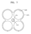
- FIGS. 5 through 7 are plane views schematically illustrating battery holders 220, 320, and 420 according to embodiments of the present invention.
- the battery holder 220 includes a plurality of mounting surfaces 222 on which two unit cells (not shown) are mounted; an insertion part 224 that is separated from the mounting surfaces 222; and a welding part 226 that is mounted on the insertion part 224.
- the battery holder 220 may have the two mounting surfaces 222 on which the two unit cells are mounted, and the welding part 226 may be formed in a gap (recess) between the two mounting surfaces 222.
- the battery holder 320 includes a plurality of mounting surfaces 322 on which three unit cells (not shown) are mounted; an insertion part 324 that is separated from the mounting surfaces 322; and a welding part 326 that is mounted on the insertion part 324.
- the battery holder 320 may have the three mounting surfaces 322 on which the three unit cells are mounted, and the welding part 326 may be formed in a gap between the three mounting surfaces 322, that is, the welding part 326 may be formed at the center of the battery holder 320.
- the battery holder 420 includes a plurality of mounting surfaces 422 on which four unit cells (not shown) are mounted; an insertion part 424 that is separated from the mounting surfaces 422; and a welding part 426 that is mounted on the insertion part 424.
- the battery holder 420 may have the four mounting surfaces 422 on which the four unit cells are mounted, and the welding part 426 may be formed in a gap between the four mounting surfaces 422, that is, the welding part 426 may be formed at the center of the battery holders 420.
- shapes of the welding parts 226, 326 and 426 are round, but one or more embodiments of the present invention are not limited thereto, thus, the shapes may vary.
Landscapes
- Chemical & Material Sciences (AREA)
- Chemical Kinetics & Catalysis (AREA)
- Electrochemistry (AREA)
- General Chemical & Material Sciences (AREA)
- Engineering & Computer Science (AREA)
- Physics & Mathematics (AREA)
- Optics & Photonics (AREA)
- Plasma & Fusion (AREA)
- Mechanical Engineering (AREA)
- Manufacturing & Machinery (AREA)
- Battery Mounting, Suspending (AREA)
- Connection Of Batteries Or Terminals (AREA)
Abstract

Description
- The present invention relates to a battery pack.
- Portable electronic devices such as notebook computers, tablet computers, smart phones, or the like have been widely used. The portable electronic devices include a battery pack for saving power so as to allow a user to use the portable electronic devices for a certain amount of time without external power supplies. The battery pack may include a plurality of battery cells consisting of secondary batteries capable of being repeatedly charged and discharged.
- When a battery pack having a plurality of battery cells is manufactured, a process for combining bus bars with electrode tabs is required.
- One or more embodiments of the present invention include a battery pack with a reduced size and capable of decreasing manufacturing costs by simplifying a manufacturing procedure.
- According to an embodiment of the present invention, there is provided a battery pack including: a plurality of unit cells; a battery holder in which the plurality of unit cells are mounted; an electrode tab arranged on the battery holder; and a bus bar of which a portion is arranged on the electrode tab, wherein the battery holder includes a welding part that contacts the electrode tab.
- The unit cells may be cylindrical cells.
- The battery holder may include: mounting surfaces on which the unit cells are mounted; and an insertion part separated from the mounting surfaces, and having a predetermined depth so as to allow the welding parts to be inserted into a top portion or a bottom portion of the battery holder.
- The welding part may be arranged at a center of a top portion or a bottom portion of the battery holder.
- A top surface of the welding part and that of the battery holder may be disposed on a same level.
- The welding part may be formed of copper or nickel.
- A top surface of the welding part and exposed terminals of the unit cells may be disposed on a same level.
- The electrode tab may cover exposed terminals of the unit cells and the welding part.
- The electrode tab may contact a top surface of the welding part.
- The electrode tab may include connections welded to terminals of the unit cells.
- The electrode tab may be formed of at least one selected from a group consisting of nickel, aluminum, copper, and silver.
- The bus bar may overlap with the welding part.
- The bus bar may be combined with the welding part via a welding process while the electrode tab is interposed between the bus bar and the welding part.
- The welding process may be a laser welding process.
- According to another embodiment of the present invention, there is provided a battery pack including: a plurality of battery holders in which a plurality of unit cells are mounted, and that are adjacent to each other; an electrode tab arranged on the battery holders; and a bus bar of which a portion is disposed on the electrode tab, wherein each of the plurality of battery holders includes: mounting surfaces on which the unit cells are mounted; an insertion part separated from the mounting surfaces, and having a predetermined depth at a top portion or a bottom portion of the each of the battery holders; and a welding part inserted into the insertion part and combined with the electrode tab.
- The electrode tab may be combined with terminals of the unit cells and the welding part.
- The welding part may be arranged at a bottom surface of the electrode tab combined with the bus bar.
- The mounting surfaces may be at least two surfaces.
- A top surface of the welding part may be arranged on a same level as terminals of the plurality of unit cells that are mounted in each of the plurality of battery holders.
- The welding part may be formed of copper or nickel.
- These and/or other aspects will become apparent and more readily appreciated from the following description of the embodiments, taken in conjunction with the accompanying drawings in which:
-
FIG. 1 is a perspective view of a battery pack according to an embodiment of the present invention; -
FIG. 2 is an exploded perspective view of the battery pack; -
FIG. 3 is a schematic cross-sectional view of the battery pack ofFIG. 1 , taken along a line A-A' ofFIG. 1 ; -
FIG. 4 is a schematic cross-sectional view of the battery pack ofFIG. 1 , taken along a line B-B' ofFIG. 1 ; and -
FIGS. 5 to 7 are plane views schematically illustrating battery holders according to embodiments of the present invention. - Reference will now be made in detail to embodiments, examples of which are illustrated in the accompanying drawings, wherein like reference numerals refer to the like elements throughout.
- Referring to
FIGS. 1 and2 , thebattery pack 100 includes a plurality of unit cells no; battery holder(s) 120 on which the plurality ofunit cells 110 are mounted;electrode tabs 130 that connect the plurality ofunit cells 110 in series or in parallel; andbus bars 140 that are electrically connected on theelectrode tabs 130. - The plurality of
unit cells 110 may be cylindrical cells. In the present embodiment, each of the plurality ofunit cells 110 includes afirst terminal 112 at one end and asecond terminal 114 at the other end. The plurality ofunit cells 110 may be lithium ion cells and may be arranged on thebattery holders 120 so that the neighboringunit cells 110 in thebattery holders 120 have identical polarity. That is, theunit cell 110 that is adjacent to anotherunit cell 110 having positive polarity at one end has positive polarity at its one end. However, one or more embodiments of the present invention are not limited thereto, thus, theunit cells 110 that are adjacent to each other may be arranged to have different polarity, according to series or parallel connections. - The plurality of
unit cells 110 may be arranged and fixed in thebattery holders 120. - Each of the
battery holders 120 includes mounting surfaces (housing portions) 122 on which theunit cell 110 is mounted; an insertion part (recess) 124 that is separated from themounting surfaces 122 and that has a predetermined depth at an upper or lower part of thebattery holder 120; and a welding part (welding material) 126 formed at theinsertion part 124. In other words, the battery holder comprises a plurality of housing portions, each for receiving a battery, and arecess 124 between the mounting portions for receiving a solder orwelding material 126. - The housing portions of the
battery holder 120 may be formed of a plastic or any appropriate material, that is capable of holding theunit cells 110 in position. - The
mounting surfaces 122 may have a round shape so as to match an outer surface of thecylindrical unit cell 110. However, the shape of themounting surfaces 122 is not limited thereto, and according to a shape of theunit cell 110, the shape of themounting surfaces 122 may vary. Also, in the present embodiment, thebattery holder 120 has eightmounting surfaces 122. However, one or more embodiments of the present invention are not limited thereto, and thus, the number of themounting surfaces 122 that are formed in thebattery holder 120 may vary according to desired charge and discharge capacities. - Also, in the present embodiment, one
unit cell 110 is mounted on onemounting surface 122 of thebattery holder 120, but one or more embodiments of the present invention are not limited thereto, and thus, a plurality of theunit cells 110 may be vertically mounted on themounting surfaces 122. - The
insertion part 124 is formed in thebattery holder 120 so as to overlap with thebus bar 140 on a certain region. For example, theinsertion part 124 may be formed at a center of thebattery holder 120 and may have a predetermined depth for receiving thewelding part 126. However, one or more embodiments of the present invention are not limited thereto, and thus theinsertion part 124 may also be formed to be close to one of themounting surfaces 122, according to a process. - The
welding part 126 may be formed in theinsertion part 124 by using a conductive material. For example, thewelding part 126 may be formed of metal such as copper or nickel, but one or more embodiments of the present invention are not limited thereto. Also, thewelding part 126 may be arranged on the same level as a top or bottom portion of theunit cell 110 mounted on themounting surfaces 122. The top portion of theunit cell 110 may be a top portion of thefirst terminal 112, and the bottom portion of theunit cell 110 may be a bottom portion of thesecond terminal 114. Alternatively, the top portion of theunit cell 100 may be a bottom portion of thesecond terminal 114, and the bottom portion of theunit cell 110 may be a top portion of thefirst terminal 112. - The
welding part 126, theelectrode tab 130 and thebus bar 140 may be arranged to overlap with each other on a certain region, and then may be combined with each other during a welding process, for example, a laser welding process. - The
electrode tab 130 is arranged on a top or bottom surface of thebattery holder 120, and is electrically connected to the plurality ofunit cells 110 that are adjacent to each other in thebattery holders 120. Theelectrode tab 130 includesconnections 132 at corners or between the corners so as to be welded to thefirst terminal 112 or thesecond terminal 114 of theunit cell 110. Also, theelectrode tab 130 is arranged on thebattery holder 120 so as to cover thewelding part 126 of thebattery holder 120. - The
electrode tab 130 may be formed of a metal material having good conductivity. For example, theelectrode tab 130 may be formed of at least one material selected from a group consisting of nickel, aluminum, copper, and silver, but one or more embodiments of the present invention are not limited thereto. Also, in the present embodiment, theelectrode tab 130 electrically connects the eightunit cells 110, but one or more embodiments of the present invention are not limited thereto. The number of theunit cells 110 that are electrically connected to oneelectrode tab 130 may vary. - The
bus bar 140 is arranged on the top surface of theelectrode tab 130 and overlaps with thewelding part 126 in a predetermined region. The bus bars 140 may be electrically and mechanically connected to theelectrode tab 130 through a welding process. - A portion of the
bus bar 140 may be arranged on the top surface of theelectrode tab 130, but the other portion of thebus bar 140 may be arranged on anotherelectrode tab 130. By doing so thebus bar 140 may function as a medium for electrically connecting twoadjacent battery holders 120. When theelectrode tabs 130 are sequentially connected by using the bus bars 140, a high-capacity battery pack 100 may be manufactured. In the present embodiment, each of the threebattery holders 120 houses the eightunit cells 110, so that thebattery pack 100 is formed, but the number of thebattery holders 120 included in thebattery pack 100 may be determined according to desired charge and discharge capacities. - The other portion of the
bus bar 140 may not be arranged on the top surface of theother electrode tab 130 but may be electrically connected, as a first terminal or a second terminal of thebattery pack 100, to an external terminal (not shown). - According to the present invention, the
battery holder 120 may include thewelding part 126 so that thebattery holder 120 may connect theelectrode tab 130 and thebus bar 140 through a welding process. - A thickness of the
electrode tab 130 that is arranged on thebattery holder 120 and electrically connects the plurality ofunit cells 110 is relatively smaller than a thickness of thebus bar 140. Therefore, there is a limit in connecting theelectrode tab 130 and thebus bar 140 by welding, but because thewelding part 126 is arranged below theelectrode tab 130, theelectrode tab 130 and thebus bar 140 may be connected through the welding process. The welding process may be a laser welding process, but one or more embodiments of the present invention are not limited thereto. - Also, the
bus bar 140 and theelectrode tab 130 may be combined with each other through the welding process, without using a coupling unit such as a bolt, so that a manufacturing procedure may be simplified, manufacturing costs may be reduced, and a size of thebattery pack 100 may be decreased. -
FIG. 3 is a schematic cross-sectional view of thebattery pack 100 ofFIG. 1 , taken along a line A-A' ofFIG. 1 , andFIG. 4 is a schematic cross-sectional view of thebattery pack 100 ofFIG. 1 , taken along a line B-B' ofFIG. 1 . - Referring to
FIG. 3 , the plurality ofunit cells 110 mounted on the mountingsurfaces 122 of thebattery holder 120 are separated from each other, and by forming theinsertion part 124 having a predetermined depth in the center of thebattery holder 120, thewelding part 126 may be mounted in theinsertion part 124. - The top surface of the
welding part 126 may be arranged on the same level as the top surface of thebattery holder 120, and the bottom surface of theelectrode tab 130 that contacts thefirst terminals 112 of theunit cells 110 may be combined with the top surface of thewelding part 126. - In more detail, the
bus bar 140 and thewelding part 126 are arranged to overlap with each other in a certain region by having theelectrode tab 130 interposed therebetween, and then thewelding part 126 having a predetermined thickness is arranged on the bottom surface of theelectrode tab 130. - Therefore, the
electrode tab 130 having a thickness relatively smaller than that of thebus bar 140 may be easily combined with thebus bar 140 through the welding process. - In addition, the top surface of the
welding part 126 may be arranged at the same level as the top portion of thefirst terminal 112 of theunit cell 110. - Because the
first terminal 112 of theunit cell 110, the upper surface of thewelding part 126 and the upper surface of thebattery holder 120 are disposed on the same level, thebattery holder 120 may be strongly combined with theelectrode tab 130. - Referring to
FIG. 4 , the bottom surface of thewelding part 126 may be arranged on the same layer as the bottom surface of thebattery holder 120, and the top surface of theelectrode tab 130 that contacts thesecond terminals 114 of theunit cells 110 is combined with the bottom surface of thewelding part 126. - In more detail, the
bus bar 140 and thewelding part 126 are arranged to overlap with each other in a certain region by having theelectrode tab 130 interposed therebetween, and thewelding part 126 having a predetermined thickness is arranged on the top portion of theelectrode tab 130 that is connected to thebus bar 140. - Also, the bottom surface of the
welding part 126 may be arranged on the same level as the bottom portion of thesecond terminal 114 of theunit cell 110. -
FIGS. 5 through 7 are plane views schematically illustratingbattery holders - Referring to
FIG. 5 , thebattery holder 220 includes a plurality of mountingsurfaces 222 on which two unit cells (not shown) are mounted; aninsertion part 224 that is separated from the mountingsurfaces 222; and awelding part 226 that is mounted on theinsertion part 224. - Unlike the
battery holder 120 illustrated inFIGS. 1 and2 , thebattery holder 220 may have the two mountingsurfaces 222 on which the two unit cells are mounted, and thewelding part 226 may be formed in a gap (recess) between the two mountingsurfaces 222. - Referring to
FIG. 6 , thebattery holder 320 includes a plurality of mountingsurfaces 322 on which three unit cells (not shown) are mounted; aninsertion part 324 that is separated from the mountingsurfaces 322; and awelding part 326 that is mounted on theinsertion part 324. - Unlike the
battery holder 120 illustrated inFIGS. 1 and2 , thebattery holder 320 may have the three mountingsurfaces 322 on which the three unit cells are mounted, and thewelding part 326 may be formed in a gap between the three mountingsurfaces 322, that is, thewelding part 326 may be formed at the center of thebattery holder 320. - Referring to
FIG. 7 , thebattery holder 420 includes a plurality of mountingsurfaces 422 on which four unit cells (not shown) are mounted; aninsertion part 424 that is separated from the mountingsurfaces 422; and awelding part 426 that is mounted on theinsertion part 424. - Unlike the
battery holder 120 illustrated inFIGS. 1 and2 , thebattery holder 420 may have the four mountingsurfaces 422 on which the four unit cells are mounted, and thewelding part 426 may be formed in a gap between the four mountingsurfaces 422, that is, thewelding part 426 may be formed at the center of thebattery holders 420. - Referring to
FIGS. 5 to 7 , shapes of thewelding parts - While this invention has been particularly shown and described with reference to preferred embodiments thereof, it will be understood by those skilled in the art that various changes in form and details may be made therein without departing from the scope of the invention as defined by the appended claims.
Claims (14)
- A battery pack comprising:a plurality of unit cells (110);a battery holder (120, 220, 320, 420) to which the plurality of unit cells are mounted;an electrode tab (130) arranged on the battery holder; anda bus bar (140) of which a portion is arranged on the electrode tab,wherein the battery holder comprises a welding part (126, 226, 326, 426) that contacts the electrode tab.
- The battery pack of claim 1, wherein the plurality of unit cells are cylindrical cells.
- The battery pack of claim 1 or 2, wherein the battery holder comprises:mounting surfaces (122, 222, 322, 422) to which the plurality of unit cells are mounted; anda recess (124, 224, 324, 424) having a predetermined depth so as to allow the welding part to be inserted into a top portion or a bottom portion of the battery holder.
- The battery pack of claim 1, 2 or 3, wherein the welding part is arranged at a center of a top portion or a bottom portion of the battery holder.
- The battery pack of any one of the preceding claims, wherein a top surface of the welding part and a top surface of the battery holder are disposed on the same level.
- The battery pack of any one of the preceding claims, wherein the welding part comprises copper or nickel.
- The battery pack of any one of the preceding claims, wherein a top surface of the welding part and exposed terminals of the plurality of unit cells are disposed on the same level.
- The battery pack of any one of the preceding claims, wherein the electrode tab covers exposed terminals of the plurality of unit cells and the welding part.
- The battery pack of any one of the preceding claims, wherein the electrode tab contacts a top surface of the welding part.
- The battery pack of any one of the preceding claims, wherein the electrode tab comprises connections welded to terminals of the plurality of unit cells.
- The battery pack of any one of the preceding claims, wherein the electrode tab comprises at least one selected from a group consisting of nickel, aluminum, copper, and silver.
- The battery pack of any one of the preceding claims, wherein the bus bar overlaps with the welding part.
- A method of making a battery pack according to any one of the preceding claims, comprising combining the bus bar with the welding part via a welding process while the electrode tab is interposed between the bus bar and the welding part.
- The method of claim 13, wherein the welding process comprises a laser welding process.
Applications Claiming Priority (1)
| Application Number | Priority Date | Filing Date | Title |
|---|---|---|---|
| KR1020130110614A KR101749509B1 (en) | 2013-09-13 | 2013-09-13 | Battery pack having welding portion |
Publications (2)
| Publication Number | Publication Date |
|---|---|
| EP2849251A1 true EP2849251A1 (en) | 2015-03-18 |
| EP2849251B1 EP2849251B1 (en) | 2016-09-28 |
Family
ID=51392171
Family Applications (1)
| Application Number | Title | Priority Date | Filing Date |
|---|---|---|---|
| EP14182275.9A Active EP2849251B1 (en) | 2013-09-13 | 2014-08-26 | Battery pack |
Country Status (5)
| Country | Link |
|---|---|
| US (1) | US9337465B2 (en) |
| EP (1) | EP2849251B1 (en) |
| JP (1) | JP6494066B2 (en) |
| KR (1) | KR101749509B1 (en) |
| CN (1) | CN104466066B (en) |
Cited By (2)
| Publication number | Priority date | Publication date | Assignee | Title |
|---|---|---|---|---|
| WO2020172648A1 (en) * | 2019-02-22 | 2020-08-27 | Tiveni Mergeco, Inc. | Electrical cell connection arrangements and method thereof |
| GB2604167A (en) * | 2021-02-26 | 2022-08-31 | Jaguar Land Rover Ltd | Laser welding systems and methods |
Families Citing this family (9)
| Publication number | Priority date | Publication date | Assignee | Title |
|---|---|---|---|---|
| US10319494B2 (en) * | 2016-02-05 | 2019-06-11 | Ematrix Energy Systems, Inc. | Multi-functional busbar with interstitial passages |
| KR102169631B1 (en) | 2017-03-21 | 2020-10-23 | 주식회사 엘지화학 | Battery module, battery pack comprising the battery module and vehicle comprising the battery pack |
| JP7199817B2 (en) * | 2018-03-16 | 2023-01-06 | 矢崎総業株式会社 | battery pack |
| JP6976890B2 (en) * | 2018-03-16 | 2021-12-08 | 矢崎総業株式会社 | Battery pack |
| CN109802064B (en) * | 2018-12-20 | 2023-12-05 | 河南新太行电源股份有限公司 | Battery mould structure of adjustable extension |
| KR102789539B1 (en) * | 2019-10-15 | 2025-03-31 | 주식회사 엘지에너지솔루션 | Battery Module Having Module Bus-bar |
| KR102673680B1 (en) | 2021-08-31 | 2024-06-10 | (주)씨오알엔 | Modular battery battery pack for easy renewability |
| KR20230064700A (en) | 2021-11-03 | 2023-05-11 | 주식회사 이지엠테크 | Waterproof, moistureproof, high current lithium-ion battery pack with internal temperature control function |
| KR102795307B1 (en) | 2022-09-19 | 2025-04-17 | (주)씨오알엔 | Modular battery pack with cooling system |
Citations (3)
| Publication number | Priority date | Publication date | Assignee | Title |
|---|---|---|---|---|
| US20080131765A1 (en) * | 2006-11-10 | 2008-06-05 | Shoji Imanaga | Battery Pack and Method for Welding Cells |
| US20120013340A1 (en) * | 2010-01-28 | 2012-01-19 | Yuasa Shin-Ichi | Battery module |
| US20130196204A1 (en) * | 2012-02-01 | 2013-08-01 | Samsung Sdi Co., Ltd. | Rechargeable battery assembly and pack including the same |
Family Cites Families (7)
| Publication number | Priority date | Publication date | Assignee | Title |
|---|---|---|---|---|
| JP4193328B2 (en) * | 2000-05-19 | 2008-12-10 | 新神戸電機株式会社 | Battery assembly, battery assembly and battery module |
| JP5119735B2 (en) * | 2007-05-16 | 2013-01-16 | ソニー株式会社 | Battery pack |
| JP5241182B2 (en) | 2007-09-11 | 2013-07-17 | 三洋電機株式会社 | Assembled battery |
| JP5306746B2 (en) * | 2007-09-26 | 2013-10-02 | 日立マクセル株式会社 | Battery pack |
| CA2721548C (en) | 2008-04-14 | 2017-10-17 | A123 Systems, Inc. | Flexible voltage nested battery module design |
| JP2011233319A (en) | 2010-04-27 | 2011-11-17 | Sanyo Electric Co Ltd | Battery pack |
| JP2012248284A (en) * | 2011-05-25 | 2012-12-13 | Kojima Press Industry Co Ltd | Battery holding connection structure |
-
2013
- 2013-09-13 KR KR1020130110614A patent/KR101749509B1/en active Active
-
2014
- 2014-04-03 US US14/244,725 patent/US9337465B2/en active Active
- 2014-07-16 JP JP2014145519A patent/JP6494066B2/en active Active
- 2014-08-14 CN CN201410399967.1A patent/CN104466066B/en active Active
- 2014-08-26 EP EP14182275.9A patent/EP2849251B1/en active Active
Patent Citations (3)
| Publication number | Priority date | Publication date | Assignee | Title |
|---|---|---|---|---|
| US20080131765A1 (en) * | 2006-11-10 | 2008-06-05 | Shoji Imanaga | Battery Pack and Method for Welding Cells |
| US20120013340A1 (en) * | 2010-01-28 | 2012-01-19 | Yuasa Shin-Ichi | Battery module |
| US20130196204A1 (en) * | 2012-02-01 | 2013-08-01 | Samsung Sdi Co., Ltd. | Rechargeable battery assembly and pack including the same |
Cited By (4)
| Publication number | Priority date | Publication date | Assignee | Title |
|---|---|---|---|---|
| WO2020172648A1 (en) * | 2019-02-22 | 2020-08-27 | Tiveni Mergeco, Inc. | Electrical cell connection arrangements and method thereof |
| GB2604167A (en) * | 2021-02-26 | 2022-08-31 | Jaguar Land Rover Ltd | Laser welding systems and methods |
| WO2022180217A1 (en) * | 2021-02-26 | 2022-09-01 | Jaguar Land Rover Limited | Laser welding systems and methods |
| GB2604167B (en) * | 2021-02-26 | 2025-05-28 | Jaguar Land Rover Ltd | Laser welding systems and methods |
Also Published As
| Publication number | Publication date |
|---|---|
| KR101749509B1 (en) | 2017-06-21 |
| US9337465B2 (en) | 2016-05-10 |
| JP2015056401A (en) | 2015-03-23 |
| JP6494066B2 (en) | 2019-04-03 |
| CN104466066A (en) | 2015-03-25 |
| EP2849251B1 (en) | 2016-09-28 |
| US20150079445A1 (en) | 2015-03-19 |
| CN104466066B (en) | 2018-11-20 |
| KR20150031092A (en) | 2015-03-23 |
Similar Documents
| Publication | Publication Date | Title |
|---|---|---|
| EP2849251B1 (en) | Battery pack | |
| EP2849262B1 (en) | Battery cell of irregular structure and battery module comprising same | |
| US9331324B2 (en) | Connector assembly and battery pack having the same | |
| CN111247662A (en) | Battery modules and battery packs with bus bars | |
| KR102444124B1 (en) | Battery module and battery pack comprising same | |
| KR101440890B1 (en) | Battery Pack | |
| CN110651379A (en) | Cylindrical battery cell with connecting cap | |
| US20180040862A1 (en) | Battery pack | |
| KR20200056715A (en) | Battery module and battery pack including the same | |
| KR100983011B1 (en) | Electrical Connecting Member for Battery Cell Based on Physical Contact Manner | |
| CN105745775B (en) | Grid arrangement for plate-shaped battery electrodes of electrochemical accumulators and accumulators | |
| CN104124405B (en) | Battery module assemblies for vehicle battery packs | |
| EP3671941B1 (en) | Secondary battery and battery pack including the same | |
| EP3671942A1 (en) | Terminal case having improved secondary battery state estimation function | |
| KR101826862B1 (en) | Battery Pack Having Protection Module | |
| CN106797045B (en) | A battery including a battery case with raised protrusions corresponding to a stepped electrode assembly | |
| CN100566007C (en) | Cylindrical lithium secondary battery and manufacturing method thereof | |
| US20120156525A1 (en) | Battery pack and manufacturing method thereof | |
| KR101039517B1 (en) | Battery cell connection member | |
| KR101805243B1 (en) | Block Type Polymer Battery And Block Type Polymer Battery Making Method | |
| KR20150006649A (en) | Battery Pack | |
| KR20170014476A (en) | Cylindrical Secondary Battery Having Circular Electrode | |
| US9190631B2 (en) | Battery pack | |
| KR101267784B1 (en) | Electrical Connecting Member Having Partition Structure and Battery Pack Manufactured Using The Same | |
| KR101542073B1 (en) | Cap Assembly of Excellent Structural Stability and Battery Pack Employed with The Same |
Legal Events
| Date | Code | Title | Description |
|---|---|---|---|
| PUAI | Public reference made under article 153(3) epc to a published international application that has entered the european phase |
Free format text: ORIGINAL CODE: 0009012 |
|
| 17P | Request for examination filed |
Effective date: 20140826 |
|
| AK | Designated contracting states |
Kind code of ref document: A1 Designated state(s): AL AT BE BG CH CY CZ DE DK EE ES FI FR GB GR HR HU IE IS IT LI LT LU LV MC MK MT NL NO PL PT RO RS SE SI SK SM TR |
|
| AX | Request for extension of the european patent |
Extension state: BA ME |
|
| R17P | Request for examination filed (corrected) |
Effective date: 20150918 |
|
| RBV | Designated contracting states (corrected) |
Designated state(s): AL AT BE BG CH CY CZ DE DK EE ES FI FR GB GR HR HU IE IS IT LI LT LU LV MC MK MT NL NO PL PT RO RS SE SI SK SM TR |
|
| GRAP | Despatch of communication of intention to grant a patent |
Free format text: ORIGINAL CODE: EPIDOSNIGR1 |
|
| RIC1 | Information provided on ipc code assigned before grant |
Ipc: B23K 26/244 20140101ALI20160321BHEP Ipc: B23K 26/40 20140101ALI20160321BHEP Ipc: H01M 2/10 20060101AFI20160321BHEP Ipc: H01M 2/20 20060101ALI20160321BHEP Ipc: B23K 103/08 20060101ALI20160321BHEP Ipc: H01R 4/02 20060101ALI20160321BHEP |
|
| INTG | Intention to grant announced |
Effective date: 20160415 |
|
| RIN1 | Information on inventor provided before grant (corrected) |
Inventor name: BAE, MIN-CHEOL Inventor name: NOH, KYOUNG-HWAN Inventor name: CHOI, HONG-KEUN Inventor name: JEONG, IK-JAE |
|
| GRAS | Grant fee paid |
Free format text: ORIGINAL CODE: EPIDOSNIGR3 |
|
| GRAA | (expected) grant |
Free format text: ORIGINAL CODE: 0009210 |
|
| AK | Designated contracting states |
Kind code of ref document: B1 Designated state(s): AL AT BE BG CH CY CZ DE DK EE ES FI FR GB GR HR HU IE IS IT LI LT LU LV MC MK MT NL NO PL PT RO RS SE SI SK SM TR |
|
| REG | Reference to a national code |
Ref country code: GB Ref legal event code: FG4D |
|
| REG | Reference to a national code |
Ref country code: CH Ref legal event code: EP |
|
| REG | Reference to a national code |
Ref country code: AT Ref legal event code: REF Ref document number: 833419 Country of ref document: AT Kind code of ref document: T Effective date: 20161015 |
|
| REG | Reference to a national code |
Ref country code: IE Ref legal event code: FG4D |
|
| REG | Reference to a national code |
Ref country code: DE Ref legal event code: R096 Ref document number: 602014003945 Country of ref document: DE |
|
| REG | Reference to a national code |
Ref country code: LT Ref legal event code: MG4D |
|
| PG25 | Lapsed in a contracting state [announced via postgrant information from national office to epo] |
Ref country code: LT Free format text: LAPSE BECAUSE OF FAILURE TO SUBMIT A TRANSLATION OF THE DESCRIPTION OR TO PAY THE FEE WITHIN THE PRESCRIBED TIME-LIMIT Effective date: 20160928 Ref country code: HR Free format text: LAPSE BECAUSE OF FAILURE TO SUBMIT A TRANSLATION OF THE DESCRIPTION OR TO PAY THE FEE WITHIN THE PRESCRIBED TIME-LIMIT Effective date: 20160928 Ref country code: RS Free format text: LAPSE BECAUSE OF FAILURE TO SUBMIT A TRANSLATION OF THE DESCRIPTION OR TO PAY THE FEE WITHIN THE PRESCRIBED TIME-LIMIT Effective date: 20160928 Ref country code: FI Free format text: LAPSE BECAUSE OF FAILURE TO SUBMIT A TRANSLATION OF THE DESCRIPTION OR TO PAY THE FEE WITHIN THE PRESCRIBED TIME-LIMIT Effective date: 20160928 Ref country code: NO Free format text: LAPSE BECAUSE OF FAILURE TO SUBMIT A TRANSLATION OF THE DESCRIPTION OR TO PAY THE FEE WITHIN THE PRESCRIBED TIME-LIMIT Effective date: 20161228 |
|
| REG | Reference to a national code |
Ref country code: NL Ref legal event code: MP Effective date: 20160928 |
|
| REG | Reference to a national code |
Ref country code: AT Ref legal event code: MK05 Ref document number: 833419 Country of ref document: AT Kind code of ref document: T Effective date: 20160928 |
|
| PG25 | Lapsed in a contracting state [announced via postgrant information from national office to epo] |
Ref country code: GR Free format text: LAPSE BECAUSE OF FAILURE TO SUBMIT A TRANSLATION OF THE DESCRIPTION OR TO PAY THE FEE WITHIN THE PRESCRIBED TIME-LIMIT Effective date: 20161229 Ref country code: LV Free format text: LAPSE BECAUSE OF FAILURE TO SUBMIT A TRANSLATION OF THE DESCRIPTION OR TO PAY THE FEE WITHIN THE PRESCRIBED TIME-LIMIT Effective date: 20160928 Ref country code: SE Free format text: LAPSE BECAUSE OF FAILURE TO SUBMIT A TRANSLATION OF THE DESCRIPTION OR TO PAY THE FEE WITHIN THE PRESCRIBED TIME-LIMIT Effective date: 20160928 Ref country code: NL Free format text: LAPSE BECAUSE OF FAILURE TO SUBMIT A TRANSLATION OF THE DESCRIPTION OR TO PAY THE FEE WITHIN THE PRESCRIBED TIME-LIMIT Effective date: 20160928 |
|
| PG25 | Lapsed in a contracting state [announced via postgrant information from national office to epo] |
Ref country code: EE Free format text: LAPSE BECAUSE OF FAILURE TO SUBMIT A TRANSLATION OF THE DESCRIPTION OR TO PAY THE FEE WITHIN THE PRESCRIBED TIME-LIMIT Effective date: 20160928 Ref country code: RO Free format text: LAPSE BECAUSE OF FAILURE TO SUBMIT A TRANSLATION OF THE DESCRIPTION OR TO PAY THE FEE WITHIN THE PRESCRIBED TIME-LIMIT Effective date: 20160928 |
|
| PG25 | Lapsed in a contracting state [announced via postgrant information from national office to epo] |
Ref country code: SM Free format text: LAPSE BECAUSE OF FAILURE TO SUBMIT A TRANSLATION OF THE DESCRIPTION OR TO PAY THE FEE WITHIN THE PRESCRIBED TIME-LIMIT Effective date: 20160928 Ref country code: PL Free format text: LAPSE BECAUSE OF FAILURE TO SUBMIT A TRANSLATION OF THE DESCRIPTION OR TO PAY THE FEE WITHIN THE PRESCRIBED TIME-LIMIT Effective date: 20160928 Ref country code: AT Free format text: LAPSE BECAUSE OF FAILURE TO SUBMIT A TRANSLATION OF THE DESCRIPTION OR TO PAY THE FEE WITHIN THE PRESCRIBED TIME-LIMIT Effective date: 20160928 Ref country code: CZ Free format text: LAPSE BECAUSE OF FAILURE TO SUBMIT A TRANSLATION OF THE DESCRIPTION OR TO PAY THE FEE WITHIN THE PRESCRIBED TIME-LIMIT Effective date: 20160928 Ref country code: ES Free format text: LAPSE BECAUSE OF FAILURE TO SUBMIT A TRANSLATION OF THE DESCRIPTION OR TO PAY THE FEE WITHIN THE PRESCRIBED TIME-LIMIT Effective date: 20160928 Ref country code: SK Free format text: LAPSE BECAUSE OF FAILURE TO SUBMIT A TRANSLATION OF THE DESCRIPTION OR TO PAY THE FEE WITHIN THE PRESCRIBED TIME-LIMIT Effective date: 20160928 Ref country code: BE Free format text: LAPSE BECAUSE OF FAILURE TO SUBMIT A TRANSLATION OF THE DESCRIPTION OR TO PAY THE FEE WITHIN THE PRESCRIBED TIME-LIMIT Effective date: 20160928 Ref country code: BG Free format text: LAPSE BECAUSE OF FAILURE TO SUBMIT A TRANSLATION OF THE DESCRIPTION OR TO PAY THE FEE WITHIN THE PRESCRIBED TIME-LIMIT Effective date: 20161228 Ref country code: PT Free format text: LAPSE BECAUSE OF FAILURE TO SUBMIT A TRANSLATION OF THE DESCRIPTION OR TO PAY THE FEE WITHIN THE PRESCRIBED TIME-LIMIT Effective date: 20170130 Ref country code: IS Free format text: LAPSE BECAUSE OF FAILURE TO SUBMIT A TRANSLATION OF THE DESCRIPTION OR TO PAY THE FEE WITHIN THE PRESCRIBED TIME-LIMIT Effective date: 20170128 |
|
| REG | Reference to a national code |
Ref country code: DE Ref legal event code: R097 Ref document number: 602014003945 Country of ref document: DE |
|
| PG25 | Lapsed in a contracting state [announced via postgrant information from national office to epo] |
Ref country code: IT Free format text: LAPSE BECAUSE OF FAILURE TO SUBMIT A TRANSLATION OF THE DESCRIPTION OR TO PAY THE FEE WITHIN THE PRESCRIBED TIME-LIMIT Effective date: 20160928 |
|
| REG | Reference to a national code |
Ref country code: FR Ref legal event code: PLFP Year of fee payment: 4 |
|
| PG25 | Lapsed in a contracting state [announced via postgrant information from national office to epo] |
Ref country code: DK Free format text: LAPSE BECAUSE OF FAILURE TO SUBMIT A TRANSLATION OF THE DESCRIPTION OR TO PAY THE FEE WITHIN THE PRESCRIBED TIME-LIMIT Effective date: 20160928 |
|
| PLBE | No opposition filed within time limit |
Free format text: ORIGINAL CODE: 0009261 |
|
| STAA | Information on the status of an ep patent application or granted ep patent |
Free format text: STATUS: NO OPPOSITION FILED WITHIN TIME LIMIT |
|
| 26N | No opposition filed |
Effective date: 20170629 |
|
| PG25 | Lapsed in a contracting state [announced via postgrant information from national office to epo] |
Ref country code: SI Free format text: LAPSE BECAUSE OF FAILURE TO SUBMIT A TRANSLATION OF THE DESCRIPTION OR TO PAY THE FEE WITHIN THE PRESCRIBED TIME-LIMIT Effective date: 20160928 |
|
| REG | Reference to a national code |
Ref country code: CH Ref legal event code: PL |
|
| PG25 | Lapsed in a contracting state [announced via postgrant information from national office to epo] |
Ref country code: MC Free format text: LAPSE BECAUSE OF FAILURE TO SUBMIT A TRANSLATION OF THE DESCRIPTION OR TO PAY THE FEE WITHIN THE PRESCRIBED TIME-LIMIT Effective date: 20160928 |
|
| PG25 | Lapsed in a contracting state [announced via postgrant information from national office to epo] |
Ref country code: CH Free format text: LAPSE BECAUSE OF NON-PAYMENT OF DUE FEES Effective date: 20170831 Ref country code: LI Free format text: LAPSE BECAUSE OF NON-PAYMENT OF DUE FEES Effective date: 20170831 |
|
| REG | Reference to a national code |
Ref country code: IE Ref legal event code: MM4A |
|
| PG25 | Lapsed in a contracting state [announced via postgrant information from national office to epo] |
Ref country code: LU Free format text: LAPSE BECAUSE OF NON-PAYMENT OF DUE FEES Effective date: 20170826 |
|
| REG | Reference to a national code |
Ref country code: FR Ref legal event code: PLFP Year of fee payment: 5 |
|
| PG25 | Lapsed in a contracting state [announced via postgrant information from national office to epo] |
Ref country code: IE Free format text: LAPSE BECAUSE OF NON-PAYMENT OF DUE FEES Effective date: 20170826 |
|
| PG25 | Lapsed in a contracting state [announced via postgrant information from national office to epo] |
Ref country code: MT Free format text: LAPSE BECAUSE OF NON-PAYMENT OF DUE FEES Effective date: 20170826 |
|
| PG25 | Lapsed in a contracting state [announced via postgrant information from national office to epo] |
Ref country code: AL Free format text: LAPSE BECAUSE OF FAILURE TO SUBMIT A TRANSLATION OF THE DESCRIPTION OR TO PAY THE FEE WITHIN THE PRESCRIBED TIME-LIMIT Effective date: 20160928 |
|
| PG25 | Lapsed in a contracting state [announced via postgrant information from national office to epo] |
Ref country code: HU Free format text: LAPSE BECAUSE OF FAILURE TO SUBMIT A TRANSLATION OF THE DESCRIPTION OR TO PAY THE FEE WITHIN THE PRESCRIBED TIME-LIMIT; INVALID AB INITIO Effective date: 20140826 |
|
| PG25 | Lapsed in a contracting state [announced via postgrant information from national office to epo] |
Ref country code: CY Free format text: LAPSE BECAUSE OF FAILURE TO SUBMIT A TRANSLATION OF THE DESCRIPTION OR TO PAY THE FEE WITHIN THE PRESCRIBED TIME-LIMIT Effective date: 20160928 |
|
| PG25 | Lapsed in a contracting state [announced via postgrant information from national office to epo] |
Ref country code: MK Free format text: LAPSE BECAUSE OF FAILURE TO SUBMIT A TRANSLATION OF THE DESCRIPTION OR TO PAY THE FEE WITHIN THE PRESCRIBED TIME-LIMIT Effective date: 20160928 |
|
| PG25 | Lapsed in a contracting state [announced via postgrant information from national office to epo] |
Ref country code: TR Free format text: LAPSE BECAUSE OF FAILURE TO SUBMIT A TRANSLATION OF THE DESCRIPTION OR TO PAY THE FEE WITHIN THE PRESCRIBED TIME-LIMIT Effective date: 20160928 |
|
| REG | Reference to a national code |
Ref country code: DE Ref legal event code: R079 Ref document number: 602014003945 Country of ref document: DE Free format text: PREVIOUS MAIN CLASS: H01M0002100000 Ipc: H01M0050200000 |
|
| P01 | Opt-out of the competence of the unified patent court (upc) registered |
Effective date: 20230528 |
|
| PGFP | Annual fee paid to national office [announced via postgrant information from national office to epo] |
Ref country code: DE Payment date: 20250805 Year of fee payment: 12 |
|
| PGFP | Annual fee paid to national office [announced via postgrant information from national office to epo] |
Ref country code: GB Payment date: 20250731 Year of fee payment: 12 |
|
| PGFP | Annual fee paid to national office [announced via postgrant information from national office to epo] |
Ref country code: FR Payment date: 20250808 Year of fee payment: 12 |