EP2849162B1 - System and method for visualization of history of events using bim model - Google Patents
System and method for visualization of history of events using bim model Download PDFInfo
- Publication number
- EP2849162B1 EP2849162B1 EP14178599.8A EP14178599A EP2849162B1 EP 2849162 B1 EP2849162 B1 EP 2849162B1 EP 14178599 A EP14178599 A EP 14178599A EP 2849162 B1 EP2849162 B1 EP 2849162B1
- Authority
- EP
- European Patent Office
- Prior art keywords
- time
- security system
- user
- sensor
- display
- Prior art date
- Legal status (The legal status is an assumption and is not a legal conclusion. Google has not performed a legal analysis and makes no representation as to the accuracy of the status listed.)
- Active
Links
Images



Classifications
-
- G—PHYSICS
- G06—COMPUTING OR CALCULATING; COUNTING
- G06F—ELECTRIC DIGITAL DATA PROCESSING
- G06F3/00—Input arrangements for transferring data to be processed into a form capable of being handled by the computer; Output arrangements for transferring data from processing unit to output unit, e.g. interface arrangements
- G06F3/01—Input arrangements or combined input and output arrangements for interaction between user and computer
- G06F3/048—Interaction techniques based on graphical user interfaces [GUI]
- G06F3/0481—Interaction techniques based on graphical user interfaces [GUI] based on specific properties of the displayed interaction object or a metaphor-based environment, e.g. interaction with desktop elements like windows or icons, or assisted by a cursor's changing behaviour or appearance
- G06F3/04815—Interaction with a metaphor-based environment or interaction object displayed as three-dimensional [3D], e.g. changing the user viewpoint with respect to the environment or object
-
- G—PHYSICS
- G06—COMPUTING OR CALCULATING; COUNTING
- G06F—ELECTRIC DIGITAL DATA PROCESSING
- G06F3/00—Input arrangements for transferring data to be processed into a form capable of being handled by the computer; Output arrangements for transferring data from processing unit to output unit, e.g. interface arrangements
- G06F3/01—Input arrangements or combined input and output arrangements for interaction between user and computer
- G06F3/048—Interaction techniques based on graphical user interfaces [GUI]
- G06F3/0481—Interaction techniques based on graphical user interfaces [GUI] based on specific properties of the displayed interaction object or a metaphor-based environment, e.g. interaction with desktop elements like windows or icons, or assisted by a cursor's changing behaviour or appearance
-
- G—PHYSICS
- G06—COMPUTING OR CALCULATING; COUNTING
- G06F—ELECTRIC DIGITAL DATA PROCESSING
- G06F3/00—Input arrangements for transferring data to be processed into a form capable of being handled by the computer; Output arrangements for transferring data from processing unit to output unit, e.g. interface arrangements
- G06F3/01—Input arrangements or combined input and output arrangements for interaction between user and computer
- G06F3/048—Interaction techniques based on graphical user interfaces [GUI]
- G06F3/0484—Interaction techniques based on graphical user interfaces [GUI] for the control of specific functions or operations, e.g. selecting or manipulating an object, an image or a displayed text element, setting a parameter value or selecting a range
- G06F3/04842—Selection of displayed objects or displayed text elements
-
- G—PHYSICS
- G06—COMPUTING OR CALCULATING; COUNTING
- G06F—ELECTRIC DIGITAL DATA PROCESSING
- G06F3/00—Input arrangements for transferring data to be processed into a form capable of being handled by the computer; Output arrangements for transferring data from processing unit to output unit, e.g. interface arrangements
- G06F3/01—Input arrangements or combined input and output arrangements for interaction between user and computer
- G06F3/048—Interaction techniques based on graphical user interfaces [GUI]
- G06F3/0484—Interaction techniques based on graphical user interfaces [GUI] for the control of specific functions or operations, e.g. selecting or manipulating an object, an image or a displayed text element, setting a parameter value or selecting a range
- G06F3/04847—Interaction techniques to control parameter settings, e.g. interaction with sliders or dials
-
- G—PHYSICS
- G06—COMPUTING OR CALCULATING; COUNTING
- G06T—IMAGE DATA PROCESSING OR GENERATION, IN GENERAL
- G06T19/00—Manipulating three-dimensional [3D] models or images for computer graphics
- G06T19/003—Navigation within 3D models or images
-
- G—PHYSICS
- G08—SIGNALLING
- G08B—SIGNALLING SYSTEMS, e.g. PERSONAL CALLING SYSTEMS; ORDER TELEGRAPHS; ALARM SYSTEMS
- G08B13/00—Burglar, theft or intruder alarms
- G08B13/18—Actuation by interference with heat, light, or radiation of shorter wavelength; Actuation by intruding sources of heat, light, or radiation of shorter wavelength
- G08B13/189—Actuation by interference with heat, light, or radiation of shorter wavelength; Actuation by intruding sources of heat, light, or radiation of shorter wavelength using passive radiation detection systems
- G08B13/194—Actuation by interference with heat, light, or radiation of shorter wavelength; Actuation by intruding sources of heat, light, or radiation of shorter wavelength using passive radiation detection systems using image scanning and comparing systems
- G08B13/196—Actuation by interference with heat, light, or radiation of shorter wavelength; Actuation by intruding sources of heat, light, or radiation of shorter wavelength using passive radiation detection systems using image scanning and comparing systems using television cameras
- G08B13/19678—User interface
- G08B13/19691—Signalling events for better perception by user, e.g. indicating alarms by making display brighter, adding text, creating a sound
-
- G—PHYSICS
- G08—SIGNALLING
- G08B—SIGNALLING SYSTEMS, e.g. PERSONAL CALLING SYSTEMS; ORDER TELEGRAPHS; ALARM SYSTEMS
- G08B13/00—Burglar, theft or intruder alarms
- G08B13/18—Actuation by interference with heat, light, or radiation of shorter wavelength; Actuation by intruding sources of heat, light, or radiation of shorter wavelength
- G08B13/189—Actuation by interference with heat, light, or radiation of shorter wavelength; Actuation by intruding sources of heat, light, or radiation of shorter wavelength using passive radiation detection systems
- G08B13/194—Actuation by interference with heat, light, or radiation of shorter wavelength; Actuation by intruding sources of heat, light, or radiation of shorter wavelength using passive radiation detection systems using image scanning and comparing systems
- G08B13/196—Actuation by interference with heat, light, or radiation of shorter wavelength; Actuation by intruding sources of heat, light, or radiation of shorter wavelength using passive radiation detection systems using image scanning and comparing systems using television cameras
- G08B13/19697—Arrangements wherein non-video detectors generate an alarm themselves
-
- G—PHYSICS
- G08—SIGNALLING
- G08B—SIGNALLING SYSTEMS, e.g. PERSONAL CALLING SYSTEMS; ORDER TELEGRAPHS; ALARM SYSTEMS
- G08B25/00—Alarm systems in which the location of the alarm condition is signalled to a central station, e.g. fire or police telegraphic systems
- G08B25/14—Central alarm receiver or annunciator arrangements
-
- H—ELECTRICITY
- H04—ELECTRIC COMMUNICATION TECHNIQUE
- H04N—PICTORIAL COMMUNICATION, e.g. TELEVISION
- H04N5/00—Details of television systems
- H04N5/76—Television signal recording
- H04N5/91—Television signal processing therefor
-
- H—ELECTRICITY
- H04—ELECTRIC COMMUNICATION TECHNIQUE
- H04N—PICTORIAL COMMUNICATION, e.g. TELEVISION
- H04N7/00—Television systems
- H04N7/18—Closed-circuit television [CCTV] systems, i.e. systems in which the video signal is not broadcast
- H04N7/181—Closed-circuit television [CCTV] systems, i.e. systems in which the video signal is not broadcast for receiving images from a plurality of remote sources
-
- G—PHYSICS
- G06—COMPUTING OR CALCULATING; COUNTING
- G06T—IMAGE DATA PROCESSING OR GENERATION, IN GENERAL
- G06T2200/00—Indexing scheme for image data processing or generation, in general
- G06T2200/24—Indexing scheme for image data processing or generation, in general involving graphical user interfaces [GUIs]
Definitions
- the field relates to security systems and more particularly to methods of tracking events within security systems.
- Security systems for the protection of homes and/or businesses are generally known. Such systems typically involve the use of one or more sensors located on the doors or windows surrounding a secured area for the detection of intruders.
- the sensors of a security system are typically monitored via an alarm panel either located within the home or business or at a central monitoring station. Upon activation of one of the sensors, the alarm panel may activate an alarm.
- security events are typically saved into an event file including an identifier of the sensor raising the alarm and a time of activation of the sensor.
- the event files are important during any investigation into events in order to determine how an intruder entered the secured area and the identity of the intruder.
- US patent, publication number 2012/0194336A1 discloses a user interface of a security system where a user can create a pop-up to view the output of a camera.
- US patent application 2013/0091432A1 discloses a user interface of a security system where video clips of a tracked object or person can be displayed in a 'results' panel.
- the present invention provides for a method of a security system and a corresponding system as claimed in the accompanying claims.
- FIG. 1 is a block diagram of a security system 10 shown generally in accordance with an illustrated embodiment. Included within the system is a number of sensors 12, 14 used to protect a secured area 16.
- the sensors may be limited switches mounted on doors and/or windows located along a periphery of the secured area that detect entry of intruders into the secured area.
- the sensors could also be motion detectors based upon passive infrared (PIR) devices or cameras that perform video processing of video images to detect changes between successive frames.
- PIR passive infrared
- the sensors could also be environmental detectors based upon any of a number of different technologies (e.g., smoke detectors, carbon monoxide detectors, natural gas detectors, etc.).
- the sensors may be monitored by a control panel 20 located within the secured area or within a central monitoring 18.
- a control panel 20 located within the secured area or within a central monitoring 18.
- the central monitoring station may respond by summoning the appropriate help (e.g., police, fire department, etc.).
- processor apparatus processors 20, 22, each operating under control of one or more computer programs 24, 26 loaded from a non-transitory computer readable medium (memory) 28.
- processors processors
- computer programs computer programs 24, 26 loaded from a non-transitory computer readable medium (memory) 28.
- non-transitory computer readable medium memory 28.
- an alarm processor that monitors the status of each of the sensors. Upon detection of activation of one of the sensors, the alarm processor may activate a local alarm 34 to notify authorized occupants of the secured area and may also summon help.
- an event processor located within the control panel may be an event processor.
- the event processor Upon activation of one of the sensors, the event processor saves an event into an event file 30, 32 or may add an entry into a preexisting event file within memory.
- the entry includes an identifier of the activated sensor and a time of the event.
- the user interface 36 may include an interactive display 38 or a display and separate keyboard 40.
- the user interface may be located on the control panel where the control panel is located within the secured area or may be a stand-alone device.
- the user interface may be used to arm or disarm the security system protecting the secured area.
- the user interface may also display alarm events.
- an authorized user may enter a personal identification number (PIN) and a function key (e.g., arm, arm away, disarm, etc.).
- PIN personal identification number
- function key e.g., arm, arm away, disarm, etc.
- the user interface may respond with a graphical indicator showing the status of the local alarm system.
- the security system may also include sensors that allow access into the secured area by authorized users.
- the sensors could be a card reader that reads an identify card carried by an authorized user and grants access into the secured area.
- the BIM may contain three-dimensional views of the secured area along with geographical coordinates of each of the sensors within the secured area.
- the BIM is used along with the event files by an event display system including one or more event processors 20, 22 to display events on the user interface under a process shown generally in FIG. 5 .
- the user enters a time through the user interface and the event processor may display events that happened at that time on a three-dimensional view of the secured area or portion of the secured area along with a graphical indicator on the three dimensional view that indicates where that event occurred.
- a respective popup is displayed that includes information about the event.
- the user identifies a time interval of interest by entering a starting time and ending time and the video processor may show the events that occurred within that time period.
- a sequence processor may also play back the events in the sequence as they occurred.
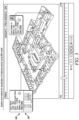
- FIG. 2 may depict a screen 100 shown on the display by one or more of the event processors.
- the screen may include a number of information elements.
- the screen includes a time scale 102 including the entered start time 104 and end time 104.
- the time scale also includes a time indicator 106.
- graphical indicators 110, 112 that show the geographical locations of sensors activated between the start time and location of the indicator 106.
- a respective popup 114, 116 that shows information associated with the respective event.
- the popup may show an identifier of the alarm, the type of alarm, the time and the status.
- a circled indicator may show the total number of alarms/alerts from the sensor during some predetermined time period.
- the screen of FIG. 2 may also include one or more function buttons 118, 120.
- the function buttons may be used to control the format of information displayed in conjunction with that time interval.
- one of the function buttons may be a playback button that plays back events as they occurred within the selected area.
- the user may first click on an icon of the BIM model displayed on the display of the user interface.
- a display processor may show a three-dimensional view of the entire secured area including an interactive window through which the user enters starting and ending times.
- the three-dimensional view may include a three-dimensional representation of the multi-story building.
- the user may select one of the stories using a cursor 121 and be presented with the three-dimensional view of one of the stories of the building.
- the user enters a start and end time and activate an enter button resulting in a display such as that shown in FIG. 2 .
- the user may select the time indicator using the cursor and drag the time indicator across the time scale.
- a time processor identifies any activated sensors that had been activated between the start time and current location of the time indicator and displays them on the screen including a popup and graphical indicator location showing the location of the sensor within the three-dimensional view.
- the user may select a playback button of the function buttons.
- the playback processor increments the location of the time indicator at some rate (e.g., 1:1 for playback at the same rate as the events occurred; 2:1 for playback at twice the rate, etc.).
- the time indicator automatically moves across the time scale incrementally displaying events based upon the location of the time indicator.
- the operator may activate a pause button of the function pushbuttons. While paused, the user may activate a view video pushbutton 124 on any of the popups. Activating the view video pushbutton cause a video processor to retrieve a sequence of video images from one or more cameras that were previously identified within the BIM as capturing images associated with the activated sensor.
- the video processor may display a sequence of images from a predetermined time period before activation of the corresponding sensor until a predetermined time after activation of the sensor.
- the images may be displayed within a separate window 126 of the popup as shown in FIG. 3 .
- the user may activate a hide video pushbutton 128.
- the screen may return to the view of FIG. 2 .
- the user may double click on the displayed view and receive a full screen view of the recorded video showing activation of the sensor.
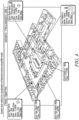
- a digest view processor may retrieve and display a history of all activated sensors over some much larger time period as shown in FIG. 4 .
- the system provides the functionality where all of the events/alarms of the system may be displayed in a specified timeframe.
- a BIM of the building or other secured area may be used to do this.
- the display of the system may have a timeline slider used in conjunction with a display under the BIM to playback the history of events/alarms that happened between the limits of the specified time.
- the user can choose the timeframe to view the history of alarms/events in the floor/premises of the building using the BIM.
- the system will play back the history of events/alarms within a 3-D display provided under the BIM of the specified floor/premises by highlighting the device (door/reader/panel).
- any activated sensor may be highlighted with different colors according to the priority of the alarm.
- the details of that event/alarm is also displayed nearby on the model using an associated window like a popup dialog with the count of the alarm/event that happened from the start to end times of the timeframe.
- a user can pause the history timeline at any time to view the events/alarms that happened at that moment and can click on the event/alarm in the popup dialog to see more detail about the alarm.
- the user can also view the recorded video on the camera nearest the device (door/reader/panel) where the alarm has occurred.
- FIG. 2 shows the timeline slider with play/pause option for the time between 1 pm and 2pm using the BIM of a building.
- the alarms/events that happened between the time limits in that time frame with its details and its count from the start time of the timeframe is shown as a popup dialog box in the diagram.
- the device from which the alarm/event originated is highlighted with different colors based on its priority.
- FIG. 3 depicts details of how a user may view the recorded video from a camera near the device (door/reader/panel) where the alarm/event occurred.
- the recorded video of the particular event/alarm is viewed by expanding the link "view video" in the event/alarm popup as shown.
- FIG. 4 depicts the "digest view” where a user can view the overlay of all events/alarms that happened during the specified timeframe in a single snapshot view. The user can drill down to see details about individual alarms/events by expanding the popup. The user can open and review the recorded video of that particular event.
- the user can instantly shift from the history timeline view to "digest view” if the user wants to see the total count of events/alarms of various devices.
- the user can switch back and forth between views as and when needed.
- the system also includes a "digest view" where a user can view the overlay of all events/alarms that happened on the specified timeframe in a single snapshot view.
- event/alarm popup the count of alarms/events that happened on the device from the start time of the timeframe will be displayed.
- the user can drill down to see details about individual alarms/events by expanding the popup.
- the user can open and review the recorded video of that particular event.
- the system solves the problem of viewing alarms/events in a number of ways.
- digest view a user can view the overlay of all events/alarms that happened on the specified timeframe in a single snapshot view.
- the system may operate by using a set of steps including a building information model (BIM) of a security system providing a three-dimensional view of a secured area of the security system including the physical location of any sensors of the security system, an input device of the security system receiving from a user a starting time and ending time of a time interval of interest and a processor of the security system displaying the three-dimensional view of the secured area including a time scale showing the starting time on one end of the time scale and the ending time at an opposing end of the time scale and a respective popup of details for each corresponding sensor of at least some sensors of the security system activated during the time interval of interest, each respective popup graphically connected to the physical location of the corresponding sensor within the three dimensional view.
- BIM building information model
- the system may accomplish these steps using apparatus including a building information model (BIM) of a security system embodied in a non-transient computer readable medium, the BIM provides a three-dimensional view of a secured area of the security system including the physical location of any sensors of the security system, an input device of the security system that receives from a user a starting time and ending time of a time interval of interest and a processor of the security system that displays the three-dimensional view of the secured area including a time scale showing the starting time on one end of the time scale and the ending time at an opposing end of the time scale and a respective popup of details for each corresponding sensor of at least some sensors of the security system activated during the time interval of interest, each respective popup graphically connected to the physical location of the corresponding sensor within the three dimensional view.
- BIM building information model
- the system may include a security system that protects a secured area, a building information model (BIM) of the security system embodied in a non-transient computer readable medium, the BIM provides a three-dimensional view of the secured area of the security system including the physical location of a plurality of sensors of the security system, an input device of the security system that receives from a user a starting time and ending time of a time interval of interest and a processor of the security system that displays the three-dimensional view of the secured area including a time scale showing the starting time on one end of the time scale and the ending time at an opposing end of the time scale and a respective popup of details for each corresponding sensor of the plurality of sensors that were activated during the time interval of interest, each respective popup graphically connected to the physical location of the corresponding sensor within the three dimensional view.
- BIM building information model
Landscapes
- Engineering & Computer Science (AREA)
- Physics & Mathematics (AREA)
- General Physics & Mathematics (AREA)
- General Engineering & Computer Science (AREA)
- Theoretical Computer Science (AREA)
- Human Computer Interaction (AREA)
- Multimedia (AREA)
- Signal Processing (AREA)
- Software Systems (AREA)
- Business, Economics & Management (AREA)
- Emergency Management (AREA)
- Remote Sensing (AREA)
- Computer Graphics (AREA)
- Computer Hardware Design (AREA)
- Radar, Positioning & Navigation (AREA)
- Alarm Systems (AREA)
Description
- The field relates to security systems and more particularly to methods of tracking events within security systems.
- Security systems for the protection of homes and/or businesses are generally known. Such systems typically involve the use of one or more sensors located on the doors or windows surrounding a secured area for the detection of intruders.
- The sensors of a security system are typically monitored via an alarm panel either located within the home or business or at a central monitoring station. Upon activation of one of the sensors, the alarm panel may activate an alarm.
- While some security systems may be monitored by a full time security guard, many security systems are only monitored indirectly via the reporting of security events to a central monitoring station. Upon detecting an alarm, the guard or central monitoring station may respond by summoning the police.
- In most cases, security events are typically saved into an event file including an identifier of the sensor raising the alarm and a time of activation of the sensor. The event files are important during any investigation into events in order to determine how an intruder entered the secured area and the identity of the intruder.
- While existing security systems work well, the security events saved into the event files are difficult to read and interpret. Accordingly, a need exists for better methods of recording and presenting such events.
-
US patent, publication number 2012/0194336A1 discloses a user interface of a security system where a user can create a pop-up to view the output of a camera.US patent application 2013/0091432A1 discloses a user interface of a security system where video clips of a tracked object or person can be displayed in a 'results' panel. - The present invention provides for a method of a security system and a corresponding system as claimed in the accompanying claims.
-
-
FIG. 1 is a block diagram of a security system shown generally in accordance with an illustrated embodiment; -
FIG. 2 depicts a screen that may be shown on a display of the system ofFIG. 1 ; -
FIG. 3 depicts a screen showing video from the system ofFIG. 1 ; -
FIG. 4 depicts a digest view of events from the system ofFIG. 1 ; and -
FIG. 5 shows a set of method steps that may be used by the system ofFIG. 1 . - While embodiments can take many different forms, specific embodiments thereof are shown in the drawings and will be described herein in detail with the understanding that the present disclosure is to be considered as an exemplification of the principles hereof, as well as the best mode of practicing same. No limitation to the specific embodiment illustrated is intended.
-
FIG. 1 is a block diagram of asecurity system 10 shown generally in accordance with an illustrated embodiment. Included within the system is a number ofsensors area 16. The sensors may be limited switches mounted on doors and/or windows located along a periphery of the secured area that detect entry of intruders into the secured area. The sensors could also be motion detectors based upon passive infrared (PIR) devices or cameras that perform video processing of video images to detect changes between successive frames. The sensors could also be environmental detectors based upon any of a number of different technologies (e.g., smoke detectors, carbon monoxide detectors, natural gas detectors, etc.). - The sensors may be monitored by a
control panel 20 located within the secured area or within acentral monitoring 18. Upon detecting activation of one of the sensors (either directly where the control panel is located at the central monitoring station or via a message sent to the central monitoring station where the control panel is located within the secured area), the central monitoring station may respond by summoning the appropriate help (e.g., police, fire department, etc.). - Located within the control panel may be one or more processor apparatus (processors) 20, 22, each operating under control of one or
more computer programs - Included within the control panel is an alarm processor that monitors the status of each of the sensors. Upon detection of activation of one of the sensors, the alarm processor may activate a
local alarm 34 to notify authorized occupants of the secured area and may also summon help. - Also located within the control panel may be an event processor. Upon activation of one of the sensors, the event processor saves an event into an
event file - Also associated with the secured area is a
user interface 36. The user interface may include aninteractive display 38 or a display andseparate keyboard 40. The user interface may be located on the control panel where the control panel is located within the secured area or may be a stand-alone device. - The user interface may be used to arm or disarm the security system protecting the secured area. The user interface may also display alarm events. In order to arm or disarm the system, an authorized user may enter a personal identification number (PIN) and a function key (e.g., arm, arm away, disarm, etc.). The user interface may respond with a graphical indicator showing the status of the local alarm system.
- In addition to the user interface, the security system may also include sensors that allow access into the secured area by authorized users. In this case, at least one of the sensors could be a card reader that reads an identify card carried by an authorized user and grants access into the secured area.
- Also included within the security system is a building information model (BIM) 42. The BIM may contain three-dimensional views of the secured area along with geographical coordinates of each of the sensors within the secured area.
- The BIM is used along with the event files by an event display system including one or
more event processors FIG. 5 . The user enters a time through the user interface and the event processor may display events that happened at that time on a three-dimensional view of the secured area or portion of the secured area along with a graphical indicator on the three dimensional view that indicates where that event occurred. In accordance with the present invention, a respective popup is displayed that includes information about the event. Further in accordance with the invention, the user identifies a time interval of interest by entering a starting time and ending time and the video processor may show the events that occurred within that time period. A sequence processor may also play back the events in the sequence as they occurred. -
FIG. 2 may depict ascreen 100 shown on the display by one or more of the event processors. The screen may include a number of information elements. The screen includes atime scale 102 including the enteredstart time 104 andend time 104. The time scale also includes atime indicator 106. - Also included within the screen may be one or more
graphical indicators indicator 106. Associated with the graphical indicators is arespective popup - The screen of
FIG. 2 may also include one ormore function buttons 118, 120. The function buttons may be used to control the format of information displayed in conjunction with that time interval. For example, one of the function buttons may be a playback button that plays back events as they occurred within the selected area. - In order to use the event display system, the user may first click on an icon of the BIM model displayed on the display of the user interface. In response, a display processor may show a three-dimensional view of the entire secured area including an interactive window through which the user enters starting and ending times. In the case where the secured area is a multistory building, the three-dimensional view may include a three-dimensional representation of the multi-story building. The user may select one of the stories using a
cursor 121 and be presented with the three-dimensional view of one of the stories of the building. The user enters a start and end time and activate an enter button resulting in a display such as that shown inFIG. 2 . - The user may select the time indicator using the cursor and drag the time indicator across the time scale. As the time indicator is dragged across the time scale, a time processor identifies any activated sensors that had been activated between the start time and current location of the time indicator and displays them on the screen including a popup and graphical indicator location showing the location of the sensor within the three-dimensional view.
- Alternatively, the user may select a playback button of the function buttons. In this case, the playback processor increments the location of the time indicator at some rate (e.g., 1:1 for playback at the same rate as the events occurred; 2:1 for playback at twice the rate, etc.). In response, the time indicator automatically moves across the time scale incrementally displaying events based upon the location of the time indicator.
- As the indicator moves across the time scale, the operator may activate a pause button of the function pushbuttons. While paused, the user may activate a
view video pushbutton 124 on any of the popups. Activating the view video pushbutton cause a video processor to retrieve a sequence of video images from one or more cameras that were previously identified within the BIM as capturing images associated with the activated sensor. - Once activated, the video processor may display a sequence of images from a predetermined time period before activation of the corresponding sensor until a predetermined time after activation of the sensor. The images may be displayed within a
separate window 126 of the popup as shown inFIG. 3 . - Once the user has viewed the images associated with the activated sensor, the user may activate a
hide video pushbutton 128. In response, the screen may return to the view ofFIG. 2 . Alternatively, the user may double click on the displayed view and receive a full screen view of the recorded video showing activation of the sensor. - In addition to viewing video, the user may also activate a digest view pushbutton of the function pushbuttons. In this case, a digest view processor may retrieve and display a history of all activated sensors over some much larger time period as shown in
FIG. 4 . - In general, the system provides the functionality where all of the events/alarms of the system may be displayed in a specified timeframe. A BIM of the building or other secured area may be used to do this. The display of the system may have a timeline slider used in conjunction with a display under the BIM to playback the history of events/alarms that happened between the limits of the specified time.
- The user can choose the timeframe to view the history of alarms/events in the floor/premises of the building using the BIM. In response, the system will play back the history of events/alarms within a 3-D display provided under the BIM of the specified floor/premises by highlighting the device (door/reader/panel). In this regard, any activated sensor may be highlighted with different colors according to the priority of the alarm. The details of that event/alarm is also displayed nearby on the model using an associated window like a popup dialog with the count of the alarm/event that happened from the start to end times of the timeframe.
- A user can pause the history timeline at any time to view the events/alarms that happened at that moment and can click on the event/alarm in the popup dialog to see more detail about the alarm. The user can also view the recorded video on the camera nearest the device (door/reader/panel) where the alarm has occurred.
-
FIG. 2 shows the timeline slider with play/pause option for the time between 1 pm and 2pm using the BIM of a building. The alarms/events that happened between the time limits in that time frame with its details and its count from the start time of the timeframe is shown as a popup dialog box in the diagram. The device from which the alarm/event originated is highlighted with different colors based on its priority. -
FIG. 3 depicts details of how a user may view the recorded video from a camera near the device (door/reader/panel) where the alarm/event occurred. The recorded video of the particular event/alarm is viewed by expanding the link "view video" in the event/alarm popup as shown. -
FIG. 4 depicts the "digest view" where a user can view the overlay of all events/alarms that happened during the specified timeframe in a single snapshot view. The user can drill down to see details about individual alarms/events by expanding the popup. The user can open and review the recorded video of that particular event. - The user can instantly shift from the history timeline view to "digest view" if the user wants to see the total count of events/alarms of various devices. The user can switch back and forth between views as and when needed.
- The system also includes a "digest view" where a user can view the overlay of all events/alarms that happened on the specified timeframe in a single snapshot view. In the event/alarm popup the count of alarms/events that happened on the device from the start time of the timeframe will be displayed. The user can drill down to see details about individual alarms/events by expanding the popup. The user can open and review the recorded video of that particular event.
- The system solves the problem of viewing alarms/events in a number of ways. First, by providing the play/pause timeline slider for the history of events/alarms in the BIM, the user can visually identify what, when and where the alarm/event occurred. Second, by specifying the count of alarms/events that happed in a time frame, a user can easily identify which region of the building is more alarm prone. By providing a method to view the recorded video on the cameras nearest the areas where the alarm happened in the BIM model itself, a user is more location aware of the context of the alarm/event. By using "digest view", a user can view the overlay of all events/alarms that happened on the specified timeframe in a single snapshot view.
- In general, the system may operate by using a set of steps including a building information model (BIM) of a security system providing a three-dimensional view of a secured area of the security system including the physical location of any sensors of the security system, an input device of the security system receiving from a user a starting time and ending time of a time interval of interest and a processor of the security system displaying the three-dimensional view of the secured area including a time scale showing the starting time on one end of the time scale and the ending time at an opposing end of the time scale and a respective popup of details for each corresponding sensor of at least some sensors of the security system activated during the time interval of interest, each respective popup graphically connected to the physical location of the corresponding sensor within the three dimensional view.
- The system may accomplish these steps using apparatus including a building information model (BIM) of a security system embodied in a non-transient computer readable medium, the BIM provides a three-dimensional view of a secured area of the security system including the physical location of any sensors of the security system, an input device of the security system that receives from a user a starting time and ending time of a time interval of interest and a processor of the security system that displays the three-dimensional view of the secured area including a time scale showing the starting time on one end of the time scale and the ending time at an opposing end of the time scale and a respective popup of details for each corresponding sensor of at least some sensors of the security system activated during the time interval of interest, each respective popup graphically connected to the physical location of the corresponding sensor within the three dimensional view.
- In alternate embodiments, the system may include a security system that protects a secured area, a building information model (BIM) of the security system embodied in a non-transient computer readable medium, the BIM provides a three-dimensional view of the secured area of the security system including the physical location of a plurality of sensors of the security system, an input device of the security system that receives from a user a starting time and ending time of a time interval of interest and a processor of the security system that displays the three-dimensional view of the secured area including a time scale showing the starting time on one end of the time scale and the ending time at an opposing end of the time scale and a respective popup of details for each corresponding sensor of the plurality of sensors that were activated during the time interval of interest, each respective popup graphically connected to the physical location of the corresponding sensor within the three dimensional view.
Claims (7)
- A method comprising:a building information model (BIM) of a security system (10) providing a three-dimensional view of a secured area (16) of the security system including the physical location of any sensors (12, 14) of the security system;if a sensor (12, 14) is activated, saving an entry into an event file (30) wherein the entry includes an identifier of the activated sensor and the time of the activation;an input device (40) of the security system receiving from a user a starting time and ending time of a time interval of interest; anda processor (20, 22) and a display (38) of the security system displaying the three-dimensional view of the secured area (16) including a time scale (102) showing the starting time input by the user on one end of the time scale and the ending time input by the user at an opposing end of the time scale and a respective popup (114, 116) of details for each sensor (12, 14) of the security system activated during the time interval of interest, each respective popup being graphically connected to the physical location of the corresponding sensor within the three dimensional view,wherein, upon a user activating the time scale (102), the processor (20, 22) and display (38) of the security system (10) play back activations of sensors (12, 14) as they occurred, including display of the respective popup (114, 116), in accordance with a time indicator (106) shown on the display incrementing along at least a portion of the time interval between the starting time and the ending time.
- The method as in claim 1 further comprising at least one respective popup including a view video activation button.
- The method as in claim 2 further comprising the user activating the view video activation button (118, 120) and viewing video associated with activation of the corresponding sensor.
- The method as in claim 1 where the corresponding sensor (12, 14) further comprises an intrusion sensor.
- The method as in claim 1 wherein the at least some sensors (12, 14) further comprises a card reader.
- The method as in claim 1 wherein the graphical connector further comprises an arrow leading from the popup to the location of the corresponding sensor.
- An apparatus comprising a building information model (BIM) of a security system, an input device of the security system and a processor and a display of the security system, all configured to perform a method as previously claimed.
Applications Claiming Priority (1)
| Application Number | Priority Date | Filing Date | Title |
|---|---|---|---|
| US13/962,228 US9412245B2 (en) | 2013-08-08 | 2013-08-08 | System and method for visualization of history of events using BIM model |
Publications (3)
| Publication Number | Publication Date |
|---|---|
| EP2849162A2 EP2849162A2 (en) | 2015-03-18 |
| EP2849162A3 EP2849162A3 (en) | 2016-11-16 |
| EP2849162B1 true EP2849162B1 (en) | 2023-04-05 |
Family
ID=51453563
Family Applications (1)
| Application Number | Title | Priority Date | Filing Date |
|---|---|---|---|
| EP14178599.8A Active EP2849162B1 (en) | 2013-08-08 | 2014-07-25 | System and method for visualization of history of events using bim model |
Country Status (4)
| Country | Link |
|---|---|
| US (3) | US9412245B2 (en) |
| EP (1) | EP2849162B1 (en) |
| CN (1) | CN104349141B (en) |
| CA (1) | CA2857886C (en) |
Families Citing this family (29)
| Publication number | Priority date | Publication date | Assignee | Title |
|---|---|---|---|---|
| US9965564B2 (en) | 2011-07-26 | 2018-05-08 | Schneider Electric It Corporation | Apparatus and method of displaying hardware status using augmented reality |
| US20160071319A1 (en) * | 2014-09-09 | 2016-03-10 | Schneider Electric It Corporation | Method to use augumented reality to function as hmi display |
| US9846487B2 (en) * | 2015-02-18 | 2017-12-19 | Honeywell International Inc. | Method of using PIR arrays for gesture recognition in security systems |
| US10635411B2 (en) * | 2015-03-12 | 2020-04-28 | Honeywell International Inc. | System and method of locating installed devices |
| US20160378268A1 (en) * | 2015-06-23 | 2016-12-29 | Honeywell International Inc. | System and method of smart incident analysis in control system using floor maps |
| CN105208431A (en) * | 2015-09-25 | 2015-12-30 | 晨星半导体股份有限公司 | Program recording method and recording device |
| US11436911B2 (en) * | 2015-09-30 | 2022-09-06 | Johnson Controls Tyco IP Holdings LLP | Sensor based system and method for premises safety and operational profiling based on drift analysis |
| US9965841B2 (en) | 2016-02-29 | 2018-05-08 | Schneider Electric USA, Inc. | Monitoring system based on image analysis of photos |
| US20180284974A1 (en) * | 2017-03-29 | 2018-10-04 | Honeywell International Inc. | Method for Recreating Time-Based Events Using a Building Monitoring System |
| CN107102604A (en) * | 2017-06-27 | 2017-08-29 | 中铁四局集团有限公司 | A device monitoring method, device and system |
| US11222081B2 (en) | 2017-11-27 | 2022-01-11 | Evoqua Water Technologies Llc | Off-line electronic documentation solutions |
| CN108184088A (en) * | 2017-11-28 | 2018-06-19 | 中建三局第二建设工程有限责任公司 | A kind of method that video monitoring is blended with Unity3D |
| CN108416076B (en) * | 2017-12-19 | 2020-06-09 | 江苏镇江建筑科学研究院集团股份有限公司 | BIM technology-based assembly type building design method |
| CN108036826A (en) * | 2018-01-20 | 2018-05-15 | 苏州科技大学 | Building intelligent monitor system |
| USD936664S1 (en) * | 2018-09-07 | 2021-11-23 | Delta Electronics, Inc. | Display screen or portion thereof with graphical user interface |
| EP3641349B1 (en) * | 2018-10-17 | 2022-02-09 | Koa Health B.V. | Method, system and computer programs for providing a location aware user model preserving the user's privacy |
| US11240058B2 (en) * | 2019-03-29 | 2022-02-01 | Qualcomm Incorporated | System and method to view occupant status and manage devices of building |
| CN110312104A (en) * | 2019-07-18 | 2019-10-08 | 中铁十八局集团有限公司 | A kind of high-altitude installation exercise efficiency Visualized management system |
| CN110378063B (en) * | 2019-07-26 | 2023-07-14 | 腾讯科技(深圳)有限公司 | Device deployment method, device, and electronic device based on smart building space |
| US11172111B2 (en) * | 2019-07-29 | 2021-11-09 | Honeywell International Inc. | Devices and methods for security camera installation planning |
| CN110460819A (en) * | 2019-09-05 | 2019-11-15 | 河南城建学院 | A construction project management system project progress data entry method |
| CN113031838B (en) * | 2019-12-25 | 2023-03-24 | 花瓣云科技有限公司 | Screen recording method and device and electronic equipment |
| CN111311203B (en) * | 2020-04-01 | 2023-08-22 | 陕西工业职业技术学院 | Engineering progress management and control system based on BIM |
| CN113626913B (en) * | 2021-08-03 | 2023-07-21 | 上海原构设计咨询有限公司 | BIM three-dimensional drawing processing system for historic building design |
| JP1735398S (en) * | 2022-02-28 | 2023-01-26 | Information display image | |
| US11934633B2 (en) * | 2022-03-14 | 2024-03-19 | Honeywell International Inc. | Method and system for visual representation of sensor-detected events |
| CA3258159A1 (en) * | 2022-06-07 | 2023-12-14 | Kingsway Enterprises (Uk) Limited | Door monitoring system |
| US12197704B2 (en) * | 2022-09-08 | 2025-01-14 | Genetec Inc. | Method and apparatus for controlling a user interface |
| CN116341084B (en) * | 2023-04-25 | 2023-11-10 | 盐城市建设工程质量检测中心有限公司 | Visualization system and method for building engineering detection |
Family Cites Families (19)
| Publication number | Priority date | Publication date | Assignee | Title |
|---|---|---|---|---|
| US20030025599A1 (en) * | 2001-05-11 | 2003-02-06 | Monroe David A. | Method and apparatus for collecting, sending, archiving and retrieving motion video and still images and notification of detected events |
| US20070008099A1 (en) * | 1999-09-01 | 2007-01-11 | Nettalon Security Systems, Inc. | Method and apparatus for remotely monitoring a site |
| US7868912B2 (en) * | 2000-10-24 | 2011-01-11 | Objectvideo, Inc. | Video surveillance system employing video primitives |
| US6989745B1 (en) * | 2001-09-06 | 2006-01-24 | Vistascape Security Systems Corp. | Sensor device for use in surveillance system |
| ATE500580T1 (en) * | 2005-03-25 | 2011-03-15 | Sensormatic Electronics Llc | INTELLIGENT CAMERA SELECTION AND OBJECT TRACKING |
| US8412021B2 (en) * | 2007-05-18 | 2013-04-02 | Fall Front Wireless Ny, Llc | Video player user interface |
| EP2142977A4 (en) * | 2007-05-02 | 2010-05-19 | Google Inc | User interfaces for web-based video player |
| US8310542B2 (en) * | 2007-11-28 | 2012-11-13 | Fuji Xerox Co., Ltd. | Segmenting time based on the geographic distribution of activity in sensor data |
| US9398266B2 (en) * | 2008-04-02 | 2016-07-19 | Hernan Carzalo | Object content navigation |
| US20100118147A1 (en) * | 2008-11-11 | 2010-05-13 | Honeywell International Inc. | Methods and apparatus for adaptively streaming video data based on a triggering event |
| EP2348416A1 (en) * | 2010-01-21 | 2011-07-27 | Software AG | Analysis system and method for analyzing continuous queries for data streams |
| US8947506B2 (en) * | 2010-08-27 | 2015-02-03 | Broadcom Corporation | Method and system for utilizing depth information for generating 3D maps |
| US8823508B2 (en) * | 2011-01-31 | 2014-09-02 | Honeywell International Inc. | User interfaces for enabling information infusion to improve situation awareness |
| US20130027561A1 (en) * | 2011-07-29 | 2013-01-31 | Panasonic Corporation | System and method for improving site operations by detecting abnormalities |
| US20130039634A1 (en) * | 2011-08-12 | 2013-02-14 | Honeywell International Inc. | System and method of creating an intelligent video clip for improved investigations in video surveillance |
| US9269243B2 (en) * | 2011-10-07 | 2016-02-23 | Siemens Aktiengesellschaft | Method and user interface for forensic video search |
| US8839109B2 (en) * | 2011-11-14 | 2014-09-16 | Utc Fire And Security Americas Corporation, Inc. | Digital video system with intelligent video selection timeline |
| US9472072B2 (en) * | 2012-05-04 | 2016-10-18 | Honeywell International Inc. | System and method of post event/alarm analysis in CCTV and integrated security systems |
| US8781293B2 (en) * | 2012-08-20 | 2014-07-15 | Gorilla Technology Inc. | Correction method for object linking across video sequences in a multiple camera video surveillance system |
-
2013
- 2013-08-08 US US13/962,228 patent/US9412245B2/en active Active
-
2014
- 2014-07-25 EP EP14178599.8A patent/EP2849162B1/en active Active
- 2014-07-28 CA CA2857886A patent/CA2857886C/en not_active Expired - Fee Related
- 2014-08-07 CN CN201410589252.2A patent/CN104349141B/en active Active
-
2016
- 2016-06-22 US US15/189,128 patent/US10241640B2/en active Active
-
2019
- 2019-03-15 US US16/355,369 patent/US11150778B2/en active Active
Also Published As
| Publication number | Publication date |
|---|---|
| CN104349141A (en) | 2015-02-11 |
| US10241640B2 (en) | 2019-03-26 |
| CA2857886A1 (en) | 2015-02-08 |
| US20190212898A1 (en) | 2019-07-11 |
| US11150778B2 (en) | 2021-10-19 |
| EP2849162A3 (en) | 2016-11-16 |
| EP2849162A2 (en) | 2015-03-18 |
| US20150043887A1 (en) | 2015-02-12 |
| US9412245B2 (en) | 2016-08-09 |
| US20160306523A1 (en) | 2016-10-20 |
| CN104349141B (en) | 2018-10-12 |
| CA2857886C (en) | 2018-05-22 |
Similar Documents
| Publication | Publication Date | Title |
|---|---|---|
| US11150778B2 (en) | System and method for visualization of history of events using BIM model | |
| CA2814366C (en) | System and method of post event/alarm analysis in cctv and integrated security systems | |
| EP2876570B1 (en) | System and method of dynamic correlation view for cloud based incident analysis and pattern detection | |
| US9984545B2 (en) | System and method of monitoring the video surveillance activities | |
| US10176683B2 (en) | Virtual panoramic thumbnail to summarize and visualize video content in video surveillance and in connected home business | |
| CN103985229B (en) | The system and method for alarm and history video playing | |
| EP2442284B1 (en) | Graphical bookmarking of video data with user inputs in video surveillance | |
| US20140362225A1 (en) | Video Tagging for Dynamic Tracking | |
| JP2017040983A (en) | Security system and person image display method | |
| CA2920242A1 (en) | Method of using pir arrays for gesture recognition in security systems | |
| WO2017029779A1 (en) | Security system, person image display method, and report creation method | |
| EP3109837A1 (en) | System and method of smart incident analysis in control system using floor maps | |
| US9990821B2 (en) | Method of restoring camera position for playing video scenario | |
| JP6268496B2 (en) | Security system and image display method | |
| CN102457718B (en) | Utilize user to input in video monitoring and video data is added graphical bookmarks |
Legal Events
| Date | Code | Title | Description |
|---|---|---|---|
| PUAI | Public reference made under article 153(3) epc to a published international application that has entered the european phase |
Free format text: ORIGINAL CODE: 0009012 |
|
| 17P | Request for examination filed |
Effective date: 20140725 |
|
| AK | Designated contracting states |
Kind code of ref document: A2 Designated state(s): AL AT BE BG CH CY CZ DE DK EE ES FI FR GB GR HR HU IE IS IT LI LT LU LV MC MK MT NL NO PL PT RO RS SE SI SK SM TR |
|
| AX | Request for extension of the european patent |
Extension state: BA ME |
|
| RAP1 | Party data changed (applicant data changed or rights of an application transferred) |
Owner name: HONEYWELL INTERNATIONAL INC. |
|
| PUAL | Search report despatched |
Free format text: ORIGINAL CODE: 0009013 |
|
| AK | Designated contracting states |
Kind code of ref document: A3 Designated state(s): AL AT BE BG CH CY CZ DE DK EE ES FI FR GB GR HR HU IE IS IT LI LT LU LV MC MK MT NL NO PL PT RO RS SE SI SK SM TR |
|
| AX | Request for extension of the european patent |
Extension state: BA ME |
|
| RIC1 | Information provided on ipc code assigned before grant |
Ipc: G08B 25/14 20060101ALI20161012BHEP Ipc: G08B 13/196 20060101AFI20161012BHEP |
|
| STAA | Information on the status of an ep patent application or granted ep patent |
Free format text: STATUS: EXAMINATION IS IN PROGRESS |
|
| 17Q | First examination report despatched |
Effective date: 20180329 |
|
| GRAP | Despatch of communication of intention to grant a patent |
Free format text: ORIGINAL CODE: EPIDOSNIGR1 |
|
| STAA | Information on the status of an ep patent application or granted ep patent |
Free format text: STATUS: GRANT OF PATENT IS INTENDED |
|
| INTG | Intention to grant announced |
Effective date: 20221117 |
|
| GRAS | Grant fee paid |
Free format text: ORIGINAL CODE: EPIDOSNIGR3 |
|
| GRAA | (expected) grant |
Free format text: ORIGINAL CODE: 0009210 |
|
| STAA | Information on the status of an ep patent application or granted ep patent |
Free format text: STATUS: THE PATENT HAS BEEN GRANTED |
|
| AK | Designated contracting states |
Kind code of ref document: B1 Designated state(s): AL AT BE BG CH CY CZ DE DK EE ES FI FR GB GR HR HU IE IS IT LI LT LU LV MC MK MT NL NO PL PT RO RS SE SI SK SM TR |
|
| REG | Reference to a national code |
Ref country code: GB Ref legal event code: FG4D |
|
| REG | Reference to a national code |
Ref country code: CH Ref legal event code: EP |
|
| REG | Reference to a national code |
Ref country code: AT Ref legal event code: REF Ref document number: 1558844 Country of ref document: AT Kind code of ref document: T Effective date: 20230415 |
|
| REG | Reference to a national code |
Ref country code: DE Ref legal event code: R096 Ref document number: 602014086590 Country of ref document: DE |
|
| REG | Reference to a national code |
Ref country code: IE Ref legal event code: FG4D |
|
| P01 | Opt-out of the competence of the unified patent court (upc) registered |
Effective date: 20230523 |
|
| REG | Reference to a national code |
Ref country code: LT Ref legal event code: MG9D |
|
| REG | Reference to a national code |
Ref country code: NL Ref legal event code: MP Effective date: 20230405 |
|
| REG | Reference to a national code |
Ref country code: AT Ref legal event code: MK05 Ref document number: 1558844 Country of ref document: AT Kind code of ref document: T Effective date: 20230405 |
|
| PG25 | Lapsed in a contracting state [announced via postgrant information from national office to epo] |
Ref country code: NL Free format text: LAPSE BECAUSE OF FAILURE TO SUBMIT A TRANSLATION OF THE DESCRIPTION OR TO PAY THE FEE WITHIN THE PRESCRIBED TIME-LIMIT Effective date: 20230405 |
|
| PG25 | Lapsed in a contracting state [announced via postgrant information from national office to epo] |
Ref country code: SE Free format text: LAPSE BECAUSE OF FAILURE TO SUBMIT A TRANSLATION OF THE DESCRIPTION OR TO PAY THE FEE WITHIN THE PRESCRIBED TIME-LIMIT Effective date: 20230405 Ref country code: PT Free format text: LAPSE BECAUSE OF FAILURE TO SUBMIT A TRANSLATION OF THE DESCRIPTION OR TO PAY THE FEE WITHIN THE PRESCRIBED TIME-LIMIT Effective date: 20230807 Ref country code: NO Free format text: LAPSE BECAUSE OF FAILURE TO SUBMIT A TRANSLATION OF THE DESCRIPTION OR TO PAY THE FEE WITHIN THE PRESCRIBED TIME-LIMIT Effective date: 20230705 Ref country code: ES Free format text: LAPSE BECAUSE OF FAILURE TO SUBMIT A TRANSLATION OF THE DESCRIPTION OR TO PAY THE FEE WITHIN THE PRESCRIBED TIME-LIMIT Effective date: 20230405 Ref country code: AT Free format text: LAPSE BECAUSE OF FAILURE TO SUBMIT A TRANSLATION OF THE DESCRIPTION OR TO PAY THE FEE WITHIN THE PRESCRIBED TIME-LIMIT Effective date: 20230405 |
|
| PG25 | Lapsed in a contracting state [announced via postgrant information from national office to epo] |
Ref country code: RS Free format text: LAPSE BECAUSE OF FAILURE TO SUBMIT A TRANSLATION OF THE DESCRIPTION OR TO PAY THE FEE WITHIN THE PRESCRIBED TIME-LIMIT Effective date: 20230405 Ref country code: PL Free format text: LAPSE BECAUSE OF FAILURE TO SUBMIT A TRANSLATION OF THE DESCRIPTION OR TO PAY THE FEE WITHIN THE PRESCRIBED TIME-LIMIT Effective date: 20230405 Ref country code: LV Free format text: LAPSE BECAUSE OF FAILURE TO SUBMIT A TRANSLATION OF THE DESCRIPTION OR TO PAY THE FEE WITHIN THE PRESCRIBED TIME-LIMIT Effective date: 20230405 Ref country code: LT Free format text: LAPSE BECAUSE OF FAILURE TO SUBMIT A TRANSLATION OF THE DESCRIPTION OR TO PAY THE FEE WITHIN THE PRESCRIBED TIME-LIMIT Effective date: 20230405 Ref country code: IS Free format text: LAPSE BECAUSE OF FAILURE TO SUBMIT A TRANSLATION OF THE DESCRIPTION OR TO PAY THE FEE WITHIN THE PRESCRIBED TIME-LIMIT Effective date: 20230805 Ref country code: HR Free format text: LAPSE BECAUSE OF FAILURE TO SUBMIT A TRANSLATION OF THE DESCRIPTION OR TO PAY THE FEE WITHIN THE PRESCRIBED TIME-LIMIT Effective date: 20230405 Ref country code: GR Free format text: LAPSE BECAUSE OF FAILURE TO SUBMIT A TRANSLATION OF THE DESCRIPTION OR TO PAY THE FEE WITHIN THE PRESCRIBED TIME-LIMIT Effective date: 20230706 Ref country code: AL Free format text: LAPSE BECAUSE OF FAILURE TO SUBMIT A TRANSLATION OF THE DESCRIPTION OR TO PAY THE FEE WITHIN THE PRESCRIBED TIME-LIMIT Effective date: 20230405 |
|
| PG25 | Lapsed in a contracting state [announced via postgrant information from national office to epo] |
Ref country code: FI Free format text: LAPSE BECAUSE OF FAILURE TO SUBMIT A TRANSLATION OF THE DESCRIPTION OR TO PAY THE FEE WITHIN THE PRESCRIBED TIME-LIMIT Effective date: 20230405 |
|
| REG | Reference to a national code |
Ref country code: DE Ref legal event code: R097 Ref document number: 602014086590 Country of ref document: DE |
|
| PG25 | Lapsed in a contracting state [announced via postgrant information from national office to epo] |
Ref country code: SK Free format text: LAPSE BECAUSE OF FAILURE TO SUBMIT A TRANSLATION OF THE DESCRIPTION OR TO PAY THE FEE WITHIN THE PRESCRIBED TIME-LIMIT Effective date: 20230405 |
|
| PG25 | Lapsed in a contracting state [announced via postgrant information from national office to epo] |
Ref country code: SM Free format text: LAPSE BECAUSE OF FAILURE TO SUBMIT A TRANSLATION OF THE DESCRIPTION OR TO PAY THE FEE WITHIN THE PRESCRIBED TIME-LIMIT Effective date: 20230405 Ref country code: SK Free format text: LAPSE BECAUSE OF FAILURE TO SUBMIT A TRANSLATION OF THE DESCRIPTION OR TO PAY THE FEE WITHIN THE PRESCRIBED TIME-LIMIT Effective date: 20230405 Ref country code: RO Free format text: LAPSE BECAUSE OF FAILURE TO SUBMIT A TRANSLATION OF THE DESCRIPTION OR TO PAY THE FEE WITHIN THE PRESCRIBED TIME-LIMIT Effective date: 20230405 Ref country code: EE Free format text: LAPSE BECAUSE OF FAILURE TO SUBMIT A TRANSLATION OF THE DESCRIPTION OR TO PAY THE FEE WITHIN THE PRESCRIBED TIME-LIMIT Effective date: 20230405 Ref country code: DK Free format text: LAPSE BECAUSE OF FAILURE TO SUBMIT A TRANSLATION OF THE DESCRIPTION OR TO PAY THE FEE WITHIN THE PRESCRIBED TIME-LIMIT Effective date: 20230405 Ref country code: CZ Free format text: LAPSE BECAUSE OF FAILURE TO SUBMIT A TRANSLATION OF THE DESCRIPTION OR TO PAY THE FEE WITHIN THE PRESCRIBED TIME-LIMIT Effective date: 20230405 |
|
| PLBE | No opposition filed within time limit |
Free format text: ORIGINAL CODE: 0009261 |
|
| STAA | Information on the status of an ep patent application or granted ep patent |
Free format text: STATUS: NO OPPOSITION FILED WITHIN TIME LIMIT |
|
| PG25 | Lapsed in a contracting state [announced via postgrant information from national office to epo] |
Ref country code: MC Free format text: LAPSE BECAUSE OF FAILURE TO SUBMIT A TRANSLATION OF THE DESCRIPTION OR TO PAY THE FEE WITHIN THE PRESCRIBED TIME-LIMIT Effective date: 20230405 |
|
| PG25 | Lapsed in a contracting state [announced via postgrant information from national office to epo] |
Ref country code: MC Free format text: LAPSE BECAUSE OF FAILURE TO SUBMIT A TRANSLATION OF THE DESCRIPTION OR TO PAY THE FEE WITHIN THE PRESCRIBED TIME-LIMIT Effective date: 20230405 |
|
| REG | Reference to a national code |
Ref country code: CH Ref legal event code: PL |
|
| 26N | No opposition filed |
Effective date: 20240108 |
|
| REG | Reference to a national code |
Ref country code: BE Ref legal event code: MM Effective date: 20230731 |
|
| PG25 | Lapsed in a contracting state [announced via postgrant information from national office to epo] |
Ref country code: LU Free format text: LAPSE BECAUSE OF NON-PAYMENT OF DUE FEES Effective date: 20230725 |
|
| PG25 | Lapsed in a contracting state [announced via postgrant information from national office to epo] |
Ref country code: LU Free format text: LAPSE BECAUSE OF NON-PAYMENT OF DUE FEES Effective date: 20230725 |
|
| REG | Reference to a national code |
Ref country code: IE Ref legal event code: MM4A |
|
| PG25 | Lapsed in a contracting state [announced via postgrant information from national office to epo] |
Ref country code: CH Free format text: LAPSE BECAUSE OF NON-PAYMENT OF DUE FEES Effective date: 20230731 |
|
| PG25 | Lapsed in a contracting state [announced via postgrant information from national office to epo] |
Ref country code: SI Free format text: LAPSE BECAUSE OF FAILURE TO SUBMIT A TRANSLATION OF THE DESCRIPTION OR TO PAY THE FEE WITHIN THE PRESCRIBED TIME-LIMIT Effective date: 20230405 |
|
| PG25 | Lapsed in a contracting state [announced via postgrant information from national office to epo] |
Ref country code: SI Free format text: LAPSE BECAUSE OF FAILURE TO SUBMIT A TRANSLATION OF THE DESCRIPTION OR TO PAY THE FEE WITHIN THE PRESCRIBED TIME-LIMIT Effective date: 20230405 Ref country code: IT Free format text: LAPSE BECAUSE OF FAILURE TO SUBMIT A TRANSLATION OF THE DESCRIPTION OR TO PAY THE FEE WITHIN THE PRESCRIBED TIME-LIMIT Effective date: 20230405 Ref country code: BE Free format text: LAPSE BECAUSE OF NON-PAYMENT OF DUE FEES Effective date: 20230731 |
|
| PG25 | Lapsed in a contracting state [announced via postgrant information from national office to epo] |
Ref country code: IE Free format text: LAPSE BECAUSE OF NON-PAYMENT OF DUE FEES Effective date: 20230725 |
|
| PG25 | Lapsed in a contracting state [announced via postgrant information from national office to epo] |
Ref country code: IE Free format text: LAPSE BECAUSE OF NON-PAYMENT OF DUE FEES Effective date: 20230725 |
|
| PG25 | Lapsed in a contracting state [announced via postgrant information from national office to epo] |
Ref country code: BG Free format text: LAPSE BECAUSE OF FAILURE TO SUBMIT A TRANSLATION OF THE DESCRIPTION OR TO PAY THE FEE WITHIN THE PRESCRIBED TIME-LIMIT Effective date: 20230405 |
|
| PG25 | Lapsed in a contracting state [announced via postgrant information from national office to epo] |
Ref country code: BG Free format text: LAPSE BECAUSE OF FAILURE TO SUBMIT A TRANSLATION OF THE DESCRIPTION OR TO PAY THE FEE WITHIN THE PRESCRIBED TIME-LIMIT Effective date: 20230405 |
|
| PG25 | Lapsed in a contracting state [announced via postgrant information from national office to epo] |
Ref country code: CY Free format text: LAPSE BECAUSE OF FAILURE TO SUBMIT A TRANSLATION OF THE DESCRIPTION OR TO PAY THE FEE WITHIN THE PRESCRIBED TIME-LIMIT; INVALID AB INITIO Effective date: 20140725 |
|
| PG25 | Lapsed in a contracting state [announced via postgrant information from national office to epo] |
Ref country code: HU Free format text: LAPSE BECAUSE OF FAILURE TO SUBMIT A TRANSLATION OF THE DESCRIPTION OR TO PAY THE FEE WITHIN THE PRESCRIBED TIME-LIMIT; INVALID AB INITIO Effective date: 20140725 |
|
| PGFP | Annual fee paid to national office [announced via postgrant information from national office to epo] |
Ref country code: DE Payment date: 20250728 Year of fee payment: 12 |
|
| PGFP | Annual fee paid to national office [announced via postgrant information from national office to epo] |
Ref country code: GB Payment date: 20250722 Year of fee payment: 12 |
|
| PGFP | Annual fee paid to national office [announced via postgrant information from national office to epo] |
Ref country code: FR Payment date: 20250725 Year of fee payment: 12 |
|
| PG25 | Lapsed in a contracting state [announced via postgrant information from national office to epo] |
Ref country code: TR Free format text: LAPSE BECAUSE OF FAILURE TO SUBMIT A TRANSLATION OF THE DESCRIPTION OR TO PAY THE FEE WITHIN THE PRESCRIBED TIME-LIMIT Effective date: 20230405 |