EP2848921A1 - Substrate defect detection mechanism - Google Patents
Substrate defect detection mechanism Download PDFInfo
- Publication number
- EP2848921A1 EP2848921A1 EP14179284.6A EP14179284A EP2848921A1 EP 2848921 A1 EP2848921 A1 EP 2848921A1 EP 14179284 A EP14179284 A EP 14179284A EP 2848921 A1 EP2848921 A1 EP 2848921A1
- Authority
- EP
- European Patent Office
- Prior art keywords
- substrate
- control unit
- light field
- field cameras
- Prior art date
- Legal status (The legal status is an assumption and is not a legal conclusion. Google has not performed a legal analysis and makes no representation as to the accuracy of the status listed.)
- Granted
Links
- 239000000758 substrate Substances 0.000 title claims abstract description 37
- 230000007547 defect Effects 0.000 title claims abstract description 23
- 230000007246 mechanism Effects 0.000 title description 4
- 238000001514 detection method Methods 0.000 title description 3
- 238000000034 method Methods 0.000 claims abstract description 12
- 238000012545 processing Methods 0.000 claims abstract description 8
- 238000012795 verification Methods 0.000 claims description 7
- 240000000254 Agrostemma githago Species 0.000 claims description 6
- 235000009899 Agrostemma githago Nutrition 0.000 claims description 6
- 238000001035 drying Methods 0.000 claims description 4
- 230000002950 deficient Effects 0.000 claims description 3
- 238000003384 imaging method Methods 0.000 claims description 2
- 238000005259 measurement Methods 0.000 claims description 2
- 238000004148 unit process Methods 0.000 claims 3
- 238000004519 manufacturing process Methods 0.000 description 2
- 230000003287 optical effect Effects 0.000 description 2
- 238000004891 communication Methods 0.000 description 1
- 238000004590 computer program Methods 0.000 description 1
- 230000001419 dependent effect Effects 0.000 description 1
- 238000010586 diagram Methods 0.000 description 1
- 230000002452 interceptive effect Effects 0.000 description 1
- 230000010355 oscillation Effects 0.000 description 1
- 230000003068 static effect Effects 0.000 description 1
- 230000037303 wrinkles Effects 0.000 description 1
Images

Classifications
-
- B—PERFORMING OPERATIONS; TRANSPORTING
- B41—PRINTING; LINING MACHINES; TYPEWRITERS; STAMPS
- B41J—TYPEWRITERS; SELECTIVE PRINTING MECHANISMS, i.e. MECHANISMS PRINTING OTHERWISE THAN FROM A FORME; CORRECTION OF TYPOGRAPHICAL ERRORS
- B41J11/00—Devices or arrangements of selective printing mechanisms, e.g. ink-jet printers or thermal printers, for supporting or handling copy material in sheet or web form
- B41J11/0005—Curl smoothing, i.e. smoothing down corrugated printing material, e.g. by pressing means acting on wrinkled printing material
-
- B—PERFORMING OPERATIONS; TRANSPORTING
- B41—PRINTING; LINING MACHINES; TYPEWRITERS; STAMPS
- B41J—TYPEWRITERS; SELECTIVE PRINTING MECHANISMS, i.e. MECHANISMS PRINTING OTHERWISE THAN FROM A FORME; CORRECTION OF TYPOGRAPHICAL ERRORS
- B41J11/00—Devices or arrangements of selective printing mechanisms, e.g. ink-jet printers or thermal printers, for supporting or handling copy material in sheet or web form
- B41J11/0095—Detecting means for copy material, e.g. for detecting or sensing presence of copy material or its leading or trailing end
-
- G—PHYSICS
- G01—MEASURING; TESTING
- G01N—INVESTIGATING OR ANALYSING MATERIALS BY DETERMINING THEIR CHEMICAL OR PHYSICAL PROPERTIES
- G01N21/00—Investigating or analysing materials by the use of optical means, i.e. using sub-millimetre waves, infrared, visible or ultraviolet light
- G01N21/84—Systems specially adapted for particular applications
- G01N21/88—Investigating the presence of flaws or contamination
- G01N21/89—Investigating the presence of flaws or contamination in moving material, e.g. running paper or textiles
- G01N21/8901—Optical details; Scanning details
- G01N21/8903—Optical details; Scanning details using a multiple detector array
-
- G—PHYSICS
- G01—MEASURING; TESTING
- G01N—INVESTIGATING OR ANALYSING MATERIALS BY DETERMINING THEIR CHEMICAL OR PHYSICAL PROPERTIES
- G01N21/00—Investigating or analysing materials by the use of optical means, i.e. using sub-millimetre waves, infrared, visible or ultraviolet light
- G01N21/84—Systems specially adapted for particular applications
- G01N21/88—Investigating the presence of flaws or contamination
- G01N21/89—Investigating the presence of flaws or contamination in moving material, e.g. running paper or textiles
- G01N21/892—Investigating the presence of flaws or contamination in moving material, e.g. running paper or textiles characterised by the flaw, defect or object feature examined
- G01N21/898—Irregularities in textured or patterned surfaces, e.g. textiles, wood
- G01N21/8983—Irregularities in textured or patterned surfaces, e.g. textiles, wood for testing textile webs, i.e. woven material
-
- B—PERFORMING OPERATIONS; TRANSPORTING
- B41—PRINTING; LINING MACHINES; TYPEWRITERS; STAMPS
- B41J—TYPEWRITERS; SELECTIVE PRINTING MECHANISMS, i.e. MECHANISMS PRINTING OTHERWISE THAN FROM A FORME; CORRECTION OF TYPOGRAPHICAL ERRORS
- B41J2203/00—Embodiments of or processes related to the control of the printing process
- B41J2203/01—Inspecting a printed medium or a medium to be printed using a sensing device
- B41J2203/011—Inspecting the shape or condition, e.g. wrinkled or warped, of a medium to be printed before printing on it
Definitions
- This invention relates generally to the field of printing systems. More particularly, the invention relates to image processing in a printing system.
- PVS print verification system
- Predictable operations and final quality are affected by attributes such as proper web tension, paper to ink-jet head gap, localized deformity (e.g., cockle), flutter and other mechanical anomalies that affect paper.
- attributes such as proper web tension, paper to ink-jet head gap, localized deformity (e.g., cockle), flutter and other mechanical anomalies that affect paper.
- Various means are currently in use to control and detect these aspects of the print or PVS system. Nonetheless, these mechanisms are static (e.g., tension gauge) or limit sensing (e.g., light beam make/break).
- tension gauge e.g., tension gauge
- limit sensing e.g., light beam make/break
- a method in one embodiment, includes one or more light field cameras recording image data of a substrate during printing to the substrate and a control unit processing the image data received from the one or more light field cameras to identify defect areas in the substrate.
- a print system in a further embodiment, includes a printhead array to apply presentation content to a substrate, one or more light field cameras to record image data of the substrate during application of the printed characters to the substrate and a control unit to process the image data received from the one or more light field cameras to identify defect areas in the substrate.
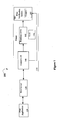
- Figure 1 illustrates one embodiment of a printing system 100.
- Printing system 100 includes a print application 110, a server 120 and a printer 130.
- Print application 110 makes a request for the printing of a document.
- print application 110 provides a print job data stream to print server 120 in a presentation format (e.g., Advanced Function Printing, Portable Document Format (PDF), Post Script, etc.).
- a presentation format e.g., Advanced Function Printing, Portable Document Format (PDF), Post Script, etc.
- Print server 120 processes pages of output that mix all of the elements normally found in presentation documents (e.g., text in typographic fonts, electronic forms, graphics, image, lines, boxes, and bar codes).
- the data stream is composed of architected, structured fields that describe each of these elements.
- printer 130 includes a control unit 140, printhead array 160 and print verification system (PVS) 180.
- print server 120 communicates with control unit 140 in order to integrate with the capabilities and command set of printer 130, and to facilitate interactive dialog between the print server 120 and printer 130.
- the dialog between the print server 120 and printer 130 is provided according to a device-dependent bi-directional command/data stream.
- Control unit 140 processes and renders objects received from print server 120 and provides sheet maps for printing to printhead array 160.
- control unit 140 includes a multitude (e.g., ten) of compute node machines, with each node having two or more parallel page output handlers (POH's).
- POH's parallel page output handlers
- PVS 180 is implemented to record mechanical defects in the substrate during printing (e.g., flutter, cockle, wrinkles or z-direction defects), as well as record print quality defects on the substrate.
- PVS 180 includes one or more cameras 185.
- cameras 185 are plenoptic cameras that use a microlens array to capture 4D light field information about a scene.
- Plenoptic cameras may also be referred to as light field cameras.
- other embodiments may feature the plenoptic cameras 185 as standalone units.
- a camera 185 has the ability to determine focus after image capture. This ability, coupled with the nature of the light source, enables capturing and managing a trans-web profile. Such a profile may be implemented to characterize web distortion (e.g., cockle, flutter, etc.) and periodicity (e.g., oscillation).
- web distortion e.g., cockle, flutter, etc.
- periodicity e.g., oscillation
- one or more plenoptic cameras 185 are installed at strategic points in printer 130 in order to utilize the light-field property to derive measurements.
- Figure 2A illustrates one embodiment of a top view of printer 130.
- printhead array 160 includes printheads 260 that apply presentation content (e.g., printed characters, graphics or other images) via ink (or toner) to a substrate as the substrates passes array 160.
- presentation content e.g., printed characters, graphics or other images
- ink or toner
- Figure 2B illustrates one embodiment of a side view of printer 130.
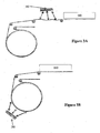
- Figure 3A illustrates one embodiment of a printer substrate path having plenoptic cameras 185 located immediately after the printhead array 160, as shown in Figures 2A and 2B .
- Figure 3B illustrates an embodiment in which plenoptic cameras 185 are located to capture a single image on a radial surface such as a drum or roller. This configuration enables a smaller footprint for print quality verification and reduced image processing requirements.
- the data collected by plenoptic cameras 185 is transmitted back to control unit 140 for processing to identify mechanical defects in the substrate during printing.
- PVS 180 may include a standalone control unit to perform the processing of the image data.
- control unit 140 may map out the surface of the substrate based on knowledge of the focal lengths of the camera 185 lenses in order to determine the focal length at various points of the substrate. This process provides a three-dimensional (3D) surface of the substrate.
- control unit 140 may focus the captured images of the web and determine, based on a magnitude of variance to get an image into focus, a degree of cockle that has occurred at the web.
- control unit 140 may process the images to determine differences in "X" or "Y" direction defects to know whether defect issues are from steering/rollers or printing/drying.
- control unit provides dynamic feedback to a paper control system (not shown) within printer 130 to correct defective regions detected during processing the image data.
- controller implements the image data to correct paper stability problems, cockling, wrinkling flutter, etc.
- cameras 185 are also implemented to capture color and print quality defects (e.g., jetouts, missing data, etc.).
- control unit 140 processes the imaging data to identify such defects.
- control unit 140 may transmit a message to a graphical user interface (GUI) 150 at printer 130 to provide defect data to an operator.
- GUI graphical user interface
- Embodiments of the invention may include various steps as set forth above.
- the steps may be embodied in machine-executable instructions.
- the instructions can be used to cause a general-purpose or special-purpose processor to perform certain steps.
- these steps may be performed by specific hardware components that contain hardwired logic for performing the steps, or by any combination of programmed computer components and custom hardware components.
- Elements of the present invention may also be provided as a machine-readable medium for storing the machine-executable instructions.
- the machine-readable medium may include, but is not limited to, floppy diskettes, optical disks, CD-ROMs, and magneto-optical disks, ROMs, RAMs, EPROMs, EEPROMs, magnetic or optical cards, propagation media or other type of media/machine-readable medium suitable for storing electronic instructions.
- the present invention may be downloaded as a computer program which may be transferred from a remote computer (e.g., a server) to a requesting computer (e.g., a client) by way of data signals embodied in a carrier wave or other propagation medium via a communication link (e.g., a modem or network connection).
- a remote computer e.g., a server
- a requesting computer e.g., a client
- a communication link e.g., a modem or network connection
Landscapes
- Textile Engineering (AREA)
- Engineering & Computer Science (AREA)
- Life Sciences & Earth Sciences (AREA)
- Analytical Chemistry (AREA)
- Health & Medical Sciences (AREA)
- Chemical & Material Sciences (AREA)
- Physics & Mathematics (AREA)
- Biochemistry (AREA)
- General Health & Medical Sciences (AREA)
- General Physics & Mathematics (AREA)
- Immunology (AREA)
- Pathology (AREA)
- Wood Science & Technology (AREA)
- Accessory Devices And Overall Control Thereof (AREA)
Abstract
Description
- This invention relates generally to the field of printing systems. More particularly, the invention relates to image processing in a printing system.
- In the high speed print production systems, relatively small variations in substrate (e.g., paper) web alignment, paper movement and surface contour can be critical. The same can be said for a print verification system (PVS) that verifies the print on the back-end of a print production system.
- Predictable operations and final quality are affected by attributes such as proper web tension, paper to ink-jet head gap, localized deformity (e.g., cockle), flutter and other mechanical anomalies that affect paper. Various means are currently in use to control and detect these aspects of the print or PVS system. Nonetheless, these mechanisms are static (e.g., tension gauge) or limit sensing (e.g., light beam make/break). The nature of the (paper) web, however, is such that simple edge or threshold sensing is insufficient.
- Accordingly, an improved detection mechanism is desired.
- In one embodiment, a method is disclosed. The method includes one or more light field cameras recording image data of a substrate during printing to the substrate and a control unit processing the image data received from the one or more light field cameras to identify defect areas in the substrate.
- In a further embodiment, a print system is disclosed. The print system includes a printhead array to apply presentation content to a substrate, one or more light field cameras to record image data of the substrate during application of the printed characters to the substrate and a control unit to process the image data received from the one or more light field cameras to identify defect areas in the substrate.
- A better understanding of the present invention can be obtained from the following detailed description in conjunction with the following drawings, in which:
-
Figure 1 illustrates one embodiment of a printing system; -
Figures 2A and 2B illustrate embodiments of a printer; and -
Figures 3A and 3B illustrate embodiments of printer substrate path implementations. - A defective substrate detection mechanism is described. In the following description, for the purposes of explanation, numerous specific details are set forth in order to provide a thorough understanding of the present invention. It will be apparent, however, to one skilled in the art that the present invention may be practiced without some of these specific details. In other instances, well-known structures and devices are shown in block diagram form to avoid obscuring the underlying principles of the present invention.
- Reference in the specification to "one embodiment" or "an embodiment" means that a particular feature, structure, or characteristic described in connection with the embodiment is included in at least one embodiment of the invention. The appearances of the phrase "in one embodiment" in various places in the specification are not necessarily all referring to the same embodiment.
-
Figure 1 illustrates one embodiment of aprinting system 100.Printing system 100 includes aprint application 110, aserver 120 and aprinter 130.Print application 110 makes a request for the printing of a document. In one embodiment,print application 110 provides a print job data stream to printserver 120 in a presentation format (e.g., Advanced Function Printing, Portable Document Format (PDF), Post Script, etc.). - Print
server 120 processes pages of output that mix all of the elements normally found in presentation documents (e.g., text in typographic fonts, electronic forms, graphics, image, lines, boxes, and bar codes). In one embodiment, the data stream is composed of architected, structured fields that describe each of these elements. - According to one embodiment,
printer 130 includes acontrol unit 140,printhead array 160 and print verification system (PVS) 180. In such an embodiment,print server 120 communicates withcontrol unit 140 in order to integrate with the capabilities and command set ofprinter 130, and to facilitate interactive dialog between theprint server 120 andprinter 130. In one embodiment, the dialog between theprint server 120 andprinter 130 is provided according to a device-dependent bi-directional command/data stream. -
Control unit 140 processes and renders objects received fromprint server 120 and provides sheet maps for printing toprinthead array 160. In such an embodiment,control unit 140 includes a multitude (e.g., ten) of compute node machines, with each node having two or more parallel page output handlers (POH's). - PVS 180 is implemented to record mechanical defects in the substrate during printing (e.g., flutter, cockle, wrinkles or z-direction defects), as well as record print quality defects on the substrate. In one embodiment,
PVS 180 includes one ormore cameras 185. In such an embodiment,cameras 185 are plenoptic cameras that use a microlens array to capture 4D light field information about a scene. Plenoptic cameras may also be referred to as light field cameras. Although described above as being incorporated withinPVS 180, other embodiments may feature theplenoptic cameras 185 as standalone units. - According to one embodiment, a
camera 185 has the ability to determine focus after image capture. This ability, coupled with the nature of the light source, enables capturing and managing a trans-web profile. Such a profile may be implemented to characterize web distortion (e.g., cockle, flutter, etc.) and periodicity (e.g., oscillation). - According to one embodiment, one or more
plenoptic cameras 185 are installed at strategic points inprinter 130 in order to utilize the light-field property to derive measurements.Figure 2A illustrates one embodiment of a top view ofprinter 130. As shown inFigure 2A ,printhead array 160 includesprintheads 260 that apply presentation content (e.g., printed characters, graphics or other images) via ink (or toner) to a substrate as the substrates passesarray 160. The substrate subsequently passes an array ofplenoptic cameras 185, which captures images of the substrate.Figure 2B illustrates one embodiment of a side view ofprinter 130. -
Figure 3A illustrates one embodiment of a printer substrate path havingplenoptic cameras 185 located immediately after theprinthead array 160, as shown inFigures 2A and 2B . However,Figure 3B illustrates an embodiment in whichplenoptic cameras 185 are located to capture a single image on a radial surface such as a drum or roller. This configuration enables a smaller footprint for print quality verification and reduced image processing requirements. - According to one embodiment, the data collected by
plenoptic cameras 185 is transmitted back tocontrol unit 140 for processing to identify mechanical defects in the substrate during printing. However in other embodiments,PVS 180 may include a standalone control unit to perform the processing of the image data. - In one embodiment,
control unit 140 may map out the surface of the substrate based on knowledge of the focal lengths of thecamera 185 lenses in order to determine the focal length at various points of the substrate. This process provides a three-dimensional (3D) surface of the substrate. In a further embodiment,control unit 140 may focus the captured images of the web and determine, based on a magnitude of variance to get an image into focus, a degree of cockle that has occurred at the web. In another embodiment,control unit 140 may process the images to determine differences in "X" or "Y" direction defects to know whether defect issues are from steering/rollers or printing/drying. - According to one embodiment, control unit provides dynamic feedback to a paper control system (not shown) within
printer 130 to correct defective regions detected during processing the image data. Thus, controller implements the image data to correct paper stability problems, cockling, wrinkling flutter, etc. - In one embodiment,
cameras 185 are also implemented to capture color and print quality defects (e.g., jetouts, missing data, etc.). In this embodiment,control unit 140 processes the imaging data to identify such defects. In yet a further embodiment,control unit 140 may transmit a message to a graphical user interface (GUI) 150 atprinter 130 to provide defect data to an operator. - Embodiments of the invention may include various steps as set forth above. The steps may be embodied in machine-executable instructions. The instructions can be used to cause a general-purpose or special-purpose processor to perform certain steps. Alternatively, these steps may be performed by specific hardware components that contain hardwired logic for performing the steps, or by any combination of programmed computer components and custom hardware components.
- Elements of the present invention may also be provided as a machine-readable medium for storing the machine-executable instructions. The machine-readable medium may include, but is not limited to, floppy diskettes, optical disks, CD-ROMs, and magneto-optical disks, ROMs, RAMs, EPROMs, EEPROMs, magnetic or optical cards, propagation media or other type of media/machine-readable medium suitable for storing electronic instructions. For example, the present invention may be downloaded as a computer program which may be transferred from a remote computer (e.g., a server) to a requesting computer (e.g., a client) by way of data signals embodied in a carrier wave or other propagation medium via a communication link (e.g., a modem or network connection).
- Throughout the foregoing description, for the purposes of explanation, numerous specific details were set forth in order to provide a thorough understanding of the invention. It will be apparent, however, to one skilled in the art that the invention may be practiced without some of these specific details. Accordingly, the scope and spirit of the invention should be judged in terms of the claims which follow.
- The present application is based on and claims the benefit of priority of
U. S. Patent Application Serial No. 13/973,088, filed on August 22, 2013
Claims (15)
- A print system comprising:a printhead array to apply printed characters to a substrate;one or more light field cameras to record image data of the substrate during application of the presentation content to the substrate; anda control unit to process the image data received from the one or more light field cameras to identify defect areas in the substrate.
- The print system of claim 1 wherein the light field cameras are located at strategic points along the substrate path to utilize the light-field property to derive measurements.
- The print system of claim 2 wherein the one or more light field cameras are located immediately after the printhead array in the substrate path.
- The print system of claim 2 wherein the one or more light field cameras are located to capture a single image on a radial surface.
- The print system of claim 1 wherein the control unit maps out a surface of the substrate based on focal lengths of the one or more light field cameras.
- The print system of claim 1 wherein the control unit focuses captured images from the image data and determines a degree of cockle that has occurred based on a magnitude of variance to focus an image.
- The print system of claim 6 wherein the control unit processes the captured images to determine differences in "X" or "Y" direction defects to know whether defect issues are from steering/ rollers or printing/drying.
- The print system of claim 7 wherein the determination of differences in "X" or "Y" direction defects permits a determination as to whether a defect is due to steering/rollers problems or printing/drying problems.
- The print system of claim 1 wherein the control unit provides dynamic feedback to a paper control system to correct defective substrate regions detected during processing the image data.
- The print system of claim 1 wherein the control unit processes the imaging data to identify color and print quality defects recorded by the one or more light field cameras.
- The print system of claim 10 wherein the control unit transmits one or more messages to a graphical user interface (GUI) to provide print quality defect data to an operator.
- A print verification system comprising:one or more light field cameras to record image data of the substrate during application of the presentation content to the substrate; anda control unit to process the image data received from the one or more light field cameras to identify defect areas in the substrate.
- The print verification system of claim 12 wherein the control unit maps out a surface of the substrate based on focal lengths of the one or more light field cameras.
- The print verification system of claim 12 wherein the control unit focuses captured images from the image data and determines a degree of cockle that has occurred based on a magnitude of variance to focus an image.
- The print verification system of claim 14 wherein the control unit processes the captured images to determine differences in "X" or "Y" direction defects to know whether defect issues are from steering/rollers or printing/drying.
Applications Claiming Priority (1)
| Application Number | Priority Date | Filing Date | Title |
|---|---|---|---|
| US13/973,088 US9132665B2 (en) | 2013-08-22 | 2013-08-22 | Substrate defect detection mechanism |
Publications (2)
| Publication Number | Publication Date |
|---|---|
| EP2848921A1 true EP2848921A1 (en) | 2015-03-18 |
| EP2848921B1 EP2848921B1 (en) | 2017-04-12 |
Family
ID=51265541
Family Applications (1)
| Application Number | Title | Priority Date | Filing Date |
|---|---|---|---|
| EP14179284.6A Not-in-force EP2848921B1 (en) | 2013-08-22 | 2014-07-31 | Substrate defect detection mechanism |
Country Status (2)
| Country | Link |
|---|---|
| US (1) | US9132665B2 (en) |
| EP (1) | EP2848921B1 (en) |
Cited By (5)
| Publication number | Priority date | Publication date | Assignee | Title |
|---|---|---|---|---|
| DE102015017054A1 (en) | 2015-05-11 | 2016-11-17 | Koenig & Bauer Ag | press |
| DE102015017056A1 (en) | 2015-05-11 | 2016-11-17 | Koenig & Bauer Ag | press |
| DE102015208713A1 (en) * | 2015-05-11 | 2016-11-17 | Koenig & Bauer Ag | press |
| DE102015017067A1 (en) | 2015-05-11 | 2016-11-17 | Koenig & Bauer Ag | press |
| DE102016123115A1 (en) * | 2016-11-30 | 2018-05-30 | Océ Holding B.V. | Method and printing device for increasing the print quality of a printing device |
Families Citing this family (2)
| Publication number | Priority date | Publication date | Assignee | Title |
|---|---|---|---|---|
| CN113592870B (en) * | 2021-10-02 | 2021-12-24 | 武汉海川彩印有限责任公司 | Printing defect detection method based on self-adaptive focal length |
| CN118583867B (en) * | 2024-08-06 | 2024-10-01 | 华南理工大学 | A dry spinning 3D printing defect identification method and system |
Citations (4)
| Publication number | Priority date | Publication date | Assignee | Title |
|---|---|---|---|---|
| US20070046715A1 (en) * | 2005-08-24 | 2007-03-01 | Fuji Photo Film Co., Ltd. | Image forming apparatus |
| US20080122890A1 (en) * | 2006-11-27 | 2008-05-29 | Mamoru Yorimoto | Image forming method and apparatus capable for preventing cockling |
| US20080291202A1 (en) * | 2007-05-23 | 2008-11-27 | Xerox Corporation | Plenoptic system for recording images from sheets |
| EP2244484A1 (en) * | 2009-04-22 | 2010-10-27 | Raytrix GmbH | Digital imaging system for synthesizing an image using data recorded with a plenoptic camera |
Family Cites Families (12)
| Publication number | Priority date | Publication date | Assignee | Title |
|---|---|---|---|---|
| US6947150B2 (en) * | 2002-05-16 | 2005-09-20 | Boise White Paper, Llc | Method and apparatus for determining out-of-plane defects in a paper sample |
| AT501432B1 (en) | 2005-02-08 | 2008-04-15 | Durst Phototech Digital Tech | INK JET PRINTING DEVICE AND METHOD FOR PRINTING MULTI-COLORED PICTURES |
| WO2007096475A1 (en) * | 2006-02-22 | 2007-08-30 | Viconsys Oy | Method for monitoring a rapidly-moving paper web and corresponding system |
| WO2009042638A2 (en) | 2007-09-27 | 2009-04-02 | Abb Ltd. | Accurate tracking of web features through converting processes |
| ES2372515B2 (en) * | 2008-01-15 | 2012-10-16 | Universidad De La Laguna | CHAMBER FOR THE REAL-TIME ACQUISITION OF THE VISUAL INFORMATION OF THREE-DIMENSIONAL SCENES. |
| US8045218B2 (en) * | 2008-10-15 | 2011-10-25 | Xerox Corporation | Digital compensation method and apparatus using image-to-image distortion map relating reference mark grids |
| US8123326B2 (en) * | 2009-09-29 | 2012-02-28 | Eastman Kodak Company | Calibration system for multi-printhead ink systems |
| US8384963B2 (en) | 2009-09-29 | 2013-02-26 | Konica Minolta Laboratory U.S.A., Inc. | System and method for monitoring output of printing devices |
| US8493616B2 (en) | 2009-10-23 | 2013-07-23 | Eastman Kodak Company | Method for identifying a media type and selecting a print mode based on the media type |
| JP5334902B2 (en) * | 2010-03-30 | 2013-11-06 | 大日本スクリーン製造株式会社 | Printing apparatus and camera position adjusting method |
| US8742309B2 (en) * | 2011-01-28 | 2014-06-03 | Aptina Imaging Corporation | Imagers with depth sensing capabilities |
| US20130163827A1 (en) * | 2011-12-21 | 2013-06-27 | Mark C. Rzadca | Method for detecting artifacts in printed content |
-
2013
- 2013-08-22 US US13/973,088 patent/US9132665B2/en active Active
-
2014
- 2014-07-31 EP EP14179284.6A patent/EP2848921B1/en not_active Not-in-force
Patent Citations (4)
| Publication number | Priority date | Publication date | Assignee | Title |
|---|---|---|---|---|
| US20070046715A1 (en) * | 2005-08-24 | 2007-03-01 | Fuji Photo Film Co., Ltd. | Image forming apparatus |
| US20080122890A1 (en) * | 2006-11-27 | 2008-05-29 | Mamoru Yorimoto | Image forming method and apparatus capable for preventing cockling |
| US20080291202A1 (en) * | 2007-05-23 | 2008-11-27 | Xerox Corporation | Plenoptic system for recording images from sheets |
| EP2244484A1 (en) * | 2009-04-22 | 2010-10-27 | Raytrix GmbH | Digital imaging system for synthesizing an image using data recorded with a plenoptic camera |
Cited By (10)
| Publication number | Priority date | Publication date | Assignee | Title |
|---|---|---|---|---|
| DE102015017054A1 (en) | 2015-05-11 | 2016-11-17 | Koenig & Bauer Ag | press |
| DE102015017056A1 (en) | 2015-05-11 | 2016-11-17 | Koenig & Bauer Ag | press |
| DE102015208713A1 (en) * | 2015-05-11 | 2016-11-17 | Koenig & Bauer Ag | press |
| DE102015017067A1 (en) | 2015-05-11 | 2016-11-17 | Koenig & Bauer Ag | press |
| DE102015208713B4 (en) * | 2015-05-11 | 2017-04-20 | Koenig & Bauer Ag | press |
| DE102015017054B4 (en) * | 2015-05-11 | 2017-05-04 | Koenig & Bauer Ag | press |
| DE102015017056B4 (en) * | 2015-05-11 | 2017-05-11 | Koenig & Bauer Ag | press |
| DE102016123115A1 (en) * | 2016-11-30 | 2018-05-30 | Océ Holding B.V. | Method and printing device for increasing the print quality of a printing device |
| US10406832B2 (en) | 2016-11-30 | 2019-09-10 | Océ Holding B.V. | Method and printer for increasing the print quality of a printer |
| DE102016123115B4 (en) * | 2016-11-30 | 2021-01-21 | Canon Production Printing Holding B.V. | Method and printing device for increasing the print quality of a printing device |
Also Published As
| Publication number | Publication date |
|---|---|
| US9132665B2 (en) | 2015-09-15 |
| US20150054880A1 (en) | 2015-02-26 |
| EP2848921B1 (en) | 2017-04-12 |
Similar Documents
| Publication | Publication Date | Title |
|---|---|---|
| EP2848921B1 (en) | Substrate defect detection mechanism | |
| USRE38957E1 (en) | Document verification and tracking system for printed material | |
| US9126404B2 (en) | Ink jet recording apparatus and method for detecting faulty discharge in ink jet recording apparatus | |
| US8888224B2 (en) | Image reading apparatus, image inspection apparatus, printing apparatus, and camera position adjustment method | |
| US10404868B2 (en) | Image defect detection | |
| JP6765858B2 (en) | Image processing methods, programs, and image processing equipment | |
| JP2011209984A5 (en) | Printing apparatus and camera position adjusting method | |
| US9440434B2 (en) | System and method for using ink drop modulation to compensate for media surface height variations in an inkjet printer | |
| US9193177B1 (en) | System for reducing cockle in media printed by an inkjet printer | |
| CN110062699B (en) | System and method for determining print conditions based on printed image samples | |
| JP6833349B2 (en) | Tray, adapter tray, recording device, information processing device, recording method, information processing method, and storage medium | |
| JP6066395B2 (en) | Image inspection apparatus and image inspection method | |
| TWI536799B (en) | Smart copy apparatus | |
| JP6100661B2 (en) | Barcode image inspection apparatus and method and program thereof | |
| US8789913B2 (en) | Printing apparatus | |
| JP2011098546A (en) | Image recorder and control method of image recorder | |
| JP2006297739A (en) | Printing system | |
| US12143552B1 (en) | Print scaling correction mechanism | |
| WO2010024019A1 (en) | Printer and method for inspecting print | |
| EP4606588A1 (en) | A method for controlling an image quality of printed substrates by an in-line scanner | |
| US20260129137A1 (en) | Print scaling correction mechanism | |
| JP2015035726A (en) | Composite device and control method thereof | |
| JP2021160252A (en) | Printer | |
| JP2010114567A (en) | Image reader having dirt detecting function | |
| JP2021084397A (en) | Image formation system and image formation method |
Legal Events
| Date | Code | Title | Description |
|---|---|---|---|
| PUAI | Public reference made under article 153(3) epc to a published international application that has entered the european phase |
Free format text: ORIGINAL CODE: 0009012 |
|
| 17P | Request for examination filed |
Effective date: 20140731 |
|
| AK | Designated contracting states |
Kind code of ref document: A1 Designated state(s): AL AT BE BG CH CY CZ DE DK EE ES FI FR GB GR HR HU IE IS IT LI LT LU LV MC MK MT NL NO PL PT RO RS SE SI SK SM TR |
|
| AX | Request for extension of the european patent |
Extension state: BA ME |
|
| GRAP | Despatch of communication of intention to grant a patent |
Free format text: ORIGINAL CODE: EPIDOSNIGR1 |
|
| RIC1 | Information provided on ipc code assigned before grant |
Ipc: G01N 21/898 20060101ALI20160615BHEP Ipc: G01N 21/89 20060101AFI20160615BHEP Ipc: B41J 11/00 20060101ALI20160615BHEP |
|
| INTG | Intention to grant announced |
Effective date: 20160712 |
|
| GRAJ | Information related to disapproval of communication of intention to grant by the applicant or resumption of examination proceedings by the epo deleted |
Free format text: ORIGINAL CODE: EPIDOSDIGR1 |
|
| GRAJ | Information related to disapproval of communication of intention to grant by the applicant or resumption of examination proceedings by the epo deleted |
Free format text: ORIGINAL CODE: EPIDOSDIGR1 |
|
| INTC | Intention to grant announced (deleted) | ||
| GRAS | Grant fee paid |
Free format text: ORIGINAL CODE: EPIDOSNIGR3 |
|
| GRAP | Despatch of communication of intention to grant a patent |
Free format text: ORIGINAL CODE: EPIDOSNIGR1 |
|
| INTG | Intention to grant announced |
Effective date: 20161216 |
|
| GRAA | (expected) grant |
Free format text: ORIGINAL CODE: 0009210 |
|
| AK | Designated contracting states |
Kind code of ref document: B1 Designated state(s): AL AT BE BG CH CY CZ DE DK EE ES FI FR GB GR HR HU IE IS IT LI LT LU LV MC MK MT NL NO PL PT RO RS SE SI SK SM TR |
|
| REG | Reference to a national code |
Ref country code: GB Ref legal event code: FG4D |
|
| REG | Reference to a national code |
Ref country code: CH Ref legal event code: EP |
|
| REG | Reference to a national code |
Ref country code: IE Ref legal event code: FG4D |
|
| REG | Reference to a national code |
Ref country code: AT Ref legal event code: REF Ref document number: 884405 Country of ref document: AT Kind code of ref document: T Effective date: 20170515 |
|
| REG | Reference to a national code |
Ref country code: DE Ref legal event code: R096 Ref document number: 602014008466 Country of ref document: DE |
|
| REG | Reference to a national code |
Ref country code: FR Ref legal event code: PLFP Year of fee payment: 4 |
|
| REG | Reference to a national code |
Ref country code: NL Ref legal event code: MP Effective date: 20170412 |
|
| REG | Reference to a national code |
Ref country code: LT Ref legal event code: MG4D |
|
| REG | Reference to a national code |
Ref country code: AT Ref legal event code: MK05 Ref document number: 884405 Country of ref document: AT Kind code of ref document: T Effective date: 20170412 |
|
| PG25 | Lapsed in a contracting state [announced via postgrant information from national office to epo] |
Ref country code: NL Free format text: LAPSE BECAUSE OF FAILURE TO SUBMIT A TRANSLATION OF THE DESCRIPTION OR TO PAY THE FEE WITHIN THE PRESCRIBED TIME-LIMIT Effective date: 20170412 |
|
| PG25 | Lapsed in a contracting state [announced via postgrant information from national office to epo] |
Ref country code: AT Free format text: LAPSE BECAUSE OF FAILURE TO SUBMIT A TRANSLATION OF THE DESCRIPTION OR TO PAY THE FEE WITHIN THE PRESCRIBED TIME-LIMIT Effective date: 20170412 Ref country code: HR Free format text: LAPSE BECAUSE OF FAILURE TO SUBMIT A TRANSLATION OF THE DESCRIPTION OR TO PAY THE FEE WITHIN THE PRESCRIBED TIME-LIMIT Effective date: 20170412 Ref country code: ES Free format text: LAPSE BECAUSE OF FAILURE TO SUBMIT A TRANSLATION OF THE DESCRIPTION OR TO PAY THE FEE WITHIN THE PRESCRIBED TIME-LIMIT Effective date: 20170412 Ref country code: FI Free format text: LAPSE BECAUSE OF FAILURE TO SUBMIT A TRANSLATION OF THE DESCRIPTION OR TO PAY THE FEE WITHIN THE PRESCRIBED TIME-LIMIT Effective date: 20170412 Ref country code: NO Free format text: LAPSE BECAUSE OF FAILURE TO SUBMIT A TRANSLATION OF THE DESCRIPTION OR TO PAY THE FEE WITHIN THE PRESCRIBED TIME-LIMIT Effective date: 20170712 Ref country code: GR Free format text: LAPSE BECAUSE OF FAILURE TO SUBMIT A TRANSLATION OF THE DESCRIPTION OR TO PAY THE FEE WITHIN THE PRESCRIBED TIME-LIMIT Effective date: 20170713 Ref country code: LT Free format text: LAPSE BECAUSE OF FAILURE TO SUBMIT A TRANSLATION OF THE DESCRIPTION OR TO PAY THE FEE WITHIN THE PRESCRIBED TIME-LIMIT Effective date: 20170412 |
|
| PG25 | Lapsed in a contracting state [announced via postgrant information from national office to epo] |
Ref country code: IS Free format text: LAPSE BECAUSE OF FAILURE TO SUBMIT A TRANSLATION OF THE DESCRIPTION OR TO PAY THE FEE WITHIN THE PRESCRIBED TIME-LIMIT Effective date: 20170812 Ref country code: LV Free format text: LAPSE BECAUSE OF FAILURE TO SUBMIT A TRANSLATION OF THE DESCRIPTION OR TO PAY THE FEE WITHIN THE PRESCRIBED TIME-LIMIT Effective date: 20170412 Ref country code: RS Free format text: LAPSE BECAUSE OF FAILURE TO SUBMIT A TRANSLATION OF THE DESCRIPTION OR TO PAY THE FEE WITHIN THE PRESCRIBED TIME-LIMIT Effective date: 20170412 Ref country code: PL Free format text: LAPSE BECAUSE OF FAILURE TO SUBMIT A TRANSLATION OF THE DESCRIPTION OR TO PAY THE FEE WITHIN THE PRESCRIBED TIME-LIMIT Effective date: 20170412 Ref country code: SE Free format text: LAPSE BECAUSE OF FAILURE TO SUBMIT A TRANSLATION OF THE DESCRIPTION OR TO PAY THE FEE WITHIN THE PRESCRIBED TIME-LIMIT Effective date: 20170412 Ref country code: BG Free format text: LAPSE BECAUSE OF FAILURE TO SUBMIT A TRANSLATION OF THE DESCRIPTION OR TO PAY THE FEE WITHIN THE PRESCRIBED TIME-LIMIT Effective date: 20170712 |
|
| REG | Reference to a national code |
Ref country code: DE Ref legal event code: R097 Ref document number: 602014008466 Country of ref document: DE |
|
| PG25 | Lapsed in a contracting state [announced via postgrant information from national office to epo] |
Ref country code: RO Free format text: LAPSE BECAUSE OF FAILURE TO SUBMIT A TRANSLATION OF THE DESCRIPTION OR TO PAY THE FEE WITHIN THE PRESCRIBED TIME-LIMIT Effective date: 20170412 Ref country code: CZ Free format text: LAPSE BECAUSE OF FAILURE TO SUBMIT A TRANSLATION OF THE DESCRIPTION OR TO PAY THE FEE WITHIN THE PRESCRIBED TIME-LIMIT Effective date: 20170412 Ref country code: SK Free format text: LAPSE BECAUSE OF FAILURE TO SUBMIT A TRANSLATION OF THE DESCRIPTION OR TO PAY THE FEE WITHIN THE PRESCRIBED TIME-LIMIT Effective date: 20170412 Ref country code: DK Free format text: LAPSE BECAUSE OF FAILURE TO SUBMIT A TRANSLATION OF THE DESCRIPTION OR TO PAY THE FEE WITHIN THE PRESCRIBED TIME-LIMIT Effective date: 20170412 Ref country code: EE Free format text: LAPSE BECAUSE OF FAILURE TO SUBMIT A TRANSLATION OF THE DESCRIPTION OR TO PAY THE FEE WITHIN THE PRESCRIBED TIME-LIMIT Effective date: 20170412 |
|
| PLBE | No opposition filed within time limit |
Free format text: ORIGINAL CODE: 0009261 |
|
| STAA | Information on the status of an ep patent application or granted ep patent |
Free format text: STATUS: NO OPPOSITION FILED WITHIN TIME LIMIT |
|
| PG25 | Lapsed in a contracting state [announced via postgrant information from national office to epo] |
Ref country code: IT Free format text: LAPSE BECAUSE OF FAILURE TO SUBMIT A TRANSLATION OF THE DESCRIPTION OR TO PAY THE FEE WITHIN THE PRESCRIBED TIME-LIMIT Effective date: 20170412 Ref country code: SM Free format text: LAPSE BECAUSE OF FAILURE TO SUBMIT A TRANSLATION OF THE DESCRIPTION OR TO PAY THE FEE WITHIN THE PRESCRIBED TIME-LIMIT Effective date: 20170412 |
|
| REG | Reference to a national code |
Ref country code: CH Ref legal event code: PL |
|
| 26N | No opposition filed |
Effective date: 20180115 |
|
| PG25 | Lapsed in a contracting state [announced via postgrant information from national office to epo] |
Ref country code: CH Free format text: LAPSE BECAUSE OF NON-PAYMENT OF DUE FEES Effective date: 20170731 Ref country code: LI Free format text: LAPSE BECAUSE OF NON-PAYMENT OF DUE FEES Effective date: 20170731 |
|
| REG | Reference to a national code |
Ref country code: IE Ref legal event code: MM4A |
|
| PG25 | Lapsed in a contracting state [announced via postgrant information from national office to epo] |
Ref country code: SI Free format text: LAPSE BECAUSE OF FAILURE TO SUBMIT A TRANSLATION OF THE DESCRIPTION OR TO PAY THE FEE WITHIN THE PRESCRIBED TIME-LIMIT Effective date: 20170412 |
|
| REG | Reference to a national code |
Ref country code: BE Ref legal event code: MM Effective date: 20170731 |
|
| PG25 | Lapsed in a contracting state [announced via postgrant information from national office to epo] |
Ref country code: LU Free format text: LAPSE BECAUSE OF NON-PAYMENT OF DUE FEES Effective date: 20170731 |
|
| REG | Reference to a national code |
Ref country code: FR Ref legal event code: PLFP Year of fee payment: 5 |
|
| PG25 | Lapsed in a contracting state [announced via postgrant information from national office to epo] |
Ref country code: IE Free format text: LAPSE BECAUSE OF NON-PAYMENT OF DUE FEES Effective date: 20170731 |
|
| PG25 | Lapsed in a contracting state [announced via postgrant information from national office to epo] |
Ref country code: BE Free format text: LAPSE BECAUSE OF NON-PAYMENT OF DUE FEES Effective date: 20170731 |
|
| PG25 | Lapsed in a contracting state [announced via postgrant information from national office to epo] |
Ref country code: MT Free format text: LAPSE BECAUSE OF NON-PAYMENT OF DUE FEES Effective date: 20170731 |
|
| PG25 | Lapsed in a contracting state [announced via postgrant information from national office to epo] |
Ref country code: MC Free format text: LAPSE BECAUSE OF FAILURE TO SUBMIT A TRANSLATION OF THE DESCRIPTION OR TO PAY THE FEE WITHIN THE PRESCRIBED TIME-LIMIT Effective date: 20170412 Ref country code: HU Free format text: LAPSE BECAUSE OF FAILURE TO SUBMIT A TRANSLATION OF THE DESCRIPTION OR TO PAY THE FEE WITHIN THE PRESCRIBED TIME-LIMIT; INVALID AB INITIO Effective date: 20140731 |
|
| PG25 | Lapsed in a contracting state [announced via postgrant information from national office to epo] |
Ref country code: CY Free format text: LAPSE BECAUSE OF FAILURE TO SUBMIT A TRANSLATION OF THE DESCRIPTION OR TO PAY THE FEE WITHIN THE PRESCRIBED TIME-LIMIT Effective date: 20170412 |
|
| PG25 | Lapsed in a contracting state [announced via postgrant information from national office to epo] |
Ref country code: MK Free format text: LAPSE BECAUSE OF FAILURE TO SUBMIT A TRANSLATION OF THE DESCRIPTION OR TO PAY THE FEE WITHIN THE PRESCRIBED TIME-LIMIT Effective date: 20170412 |
|
| PG25 | Lapsed in a contracting state [announced via postgrant information from national office to epo] |
Ref country code: TR Free format text: LAPSE BECAUSE OF FAILURE TO SUBMIT A TRANSLATION OF THE DESCRIPTION OR TO PAY THE FEE WITHIN THE PRESCRIBED TIME-LIMIT Effective date: 20170412 |
|
| PG25 | Lapsed in a contracting state [announced via postgrant information from national office to epo] |
Ref country code: PT Free format text: LAPSE BECAUSE OF FAILURE TO SUBMIT A TRANSLATION OF THE DESCRIPTION OR TO PAY THE FEE WITHIN THE PRESCRIBED TIME-LIMIT Effective date: 20170412 |
|
| PG25 | Lapsed in a contracting state [announced via postgrant information from national office to epo] |
Ref country code: AL Free format text: LAPSE BECAUSE OF FAILURE TO SUBMIT A TRANSLATION OF THE DESCRIPTION OR TO PAY THE FEE WITHIN THE PRESCRIBED TIME-LIMIT Effective date: 20170412 |
|
| PGFP | Annual fee paid to national office [announced via postgrant information from national office to epo] |
Ref country code: GB Payment date: 20220721 Year of fee payment: 9 Ref country code: DE Payment date: 20220620 Year of fee payment: 9 |
|
| PGFP | Annual fee paid to national office [announced via postgrant information from national office to epo] |
Ref country code: FR Payment date: 20220720 Year of fee payment: 9 |
|
| REG | Reference to a national code |
Ref country code: DE Ref legal event code: R119 Ref document number: 602014008466 Country of ref document: DE |
|
| GBPC | Gb: european patent ceased through non-payment of renewal fee |
Effective date: 20230731 |
|
| PG25 | Lapsed in a contracting state [announced via postgrant information from national office to epo] |
Ref country code: DE Free format text: LAPSE BECAUSE OF NON-PAYMENT OF DUE FEES Effective date: 20240201 Ref country code: GB Free format text: LAPSE BECAUSE OF NON-PAYMENT OF DUE FEES Effective date: 20230731 |
|
| PG25 | Lapsed in a contracting state [announced via postgrant information from national office to epo] |
Ref country code: FR Free format text: LAPSE BECAUSE OF NON-PAYMENT OF DUE FEES Effective date: 20230731 |