EP2848919B1 - Method and apparatus for creating images of fibrous structures - Google Patents
Method and apparatus for creating images of fibrous structures Download PDFInfo
- Publication number
- EP2848919B1 EP2848919B1 EP13184818.6A EP13184818A EP2848919B1 EP 2848919 B1 EP2848919 B1 EP 2848919B1 EP 13184818 A EP13184818 A EP 13184818A EP 2848919 B1 EP2848919 B1 EP 2848919B1
- Authority
- EP
- European Patent Office
- Prior art keywords
- hair
- light source
- material holder
- image capture
- capture element
- Prior art date
- Legal status (The legal status is an assumption and is not a legal conclusion. Google has not performed a legal analysis and makes no representation as to the accuracy of the status listed.)
- Active
Links
Images


Classifications
-
- G—PHYSICS
- G06—COMPUTING OR CALCULATING; COUNTING
- G06T—IMAGE DATA PROCESSING OR GENERATION, IN GENERAL
- G06T5/00—Image enhancement or restoration
- G06T5/77—Retouching; Inpainting; Scratch removal
-
- G—PHYSICS
- G01—MEASURING; TESTING
- G01N—INVESTIGATING OR ANALYSING MATERIALS BY DETERMINING THEIR CHEMICAL OR PHYSICAL PROPERTIES
- G01N21/00—Investigating or analysing materials by the use of optical means, i.e. using sub-millimetre waves, infrared, visible or ultraviolet light
- G01N21/17—Systems in which incident light is modified in accordance with the properties of the material investigated
- G01N21/47—Scattering, i.e. diffuse reflection
- G01N21/4738—Diffuse reflection, e.g. also for testing fluids, fibrous materials
-
- H—ELECTRICITY
- H04—ELECTRIC COMMUNICATION TECHNIQUE
- H04N—PICTORIAL COMMUNICATION, e.g. TELEVISION
- H04N23/00—Cameras or camera modules comprising electronic image sensors; Control thereof
- H04N23/56—Cameras or camera modules comprising electronic image sensors; Control thereof provided with illuminating means
-
- G—PHYSICS
- G01—MEASURING; TESTING
- G01N—INVESTIGATING OR ANALYSING MATERIALS BY DETERMINING THEIR CHEMICAL OR PHYSICAL PROPERTIES
- G01N21/00—Investigating or analysing materials by the use of optical means, i.e. using sub-millimetre waves, infrared, visible or ultraviolet light
- G01N21/01—Arrangements or apparatus for facilitating the optical investigation
- G01N21/03—Cuvette constructions
- G01N2021/0339—Holders for solids, powders
-
- G—PHYSICS
- G01—MEASURING; TESTING
- G01N—INVESTIGATING OR ANALYSING MATERIALS BY DETERMINING THEIR CHEMICAL OR PHYSICAL PROPERTIES
- G01N21/00—Investigating or analysing materials by the use of optical means, i.e. using sub-millimetre waves, infrared, visible or ultraviolet light
- G01N21/17—Systems in which incident light is modified in accordance with the properties of the material investigated
- G01N21/47—Scattering, i.e. diffuse reflection
- G01N21/4738—Diffuse reflection, e.g. also for testing fluids, fibrous materials
- G01N2021/4764—Special kinds of physical applications
-
- G—PHYSICS
- G01—MEASURING; TESTING
- G01N—INVESTIGATING OR ANALYSING MATERIALS BY DETERMINING THEIR CHEMICAL OR PHYSICAL PROPERTIES
- G01N2201/00—Features of devices classified in G01N21/00
- G01N2201/06—Illumination; Optics
- G01N2201/063—Illuminating optical parts
- G01N2201/0633—Directed, collimated illumination
-
- G—PHYSICS
- G06—COMPUTING OR CALCULATING; COUNTING
- G06T—IMAGE DATA PROCESSING OR GENERATION, IN GENERAL
- G06T2207/00—Indexing scheme for image analysis or image enhancement
- G06T2207/10—Image acquisition modality
- G06T2207/10024—Color image
Definitions
- the invention relates to apparatus and methods for creating images of fibrous structures.
- the inventions relates particularly to apparatus for capturing information related to actual fibrous structures and methods for utilizing that information to create images of virtual fibrous structures.
- the invention concerns an apparatus according to claim 1 and a method according to claim 3.
- Dependent claim 2 concerns a particular embodiment of the apparatus.
- ARNO ZINKE et al describes "A practical approach for photometric acquisition of hair color", ACM SIGGRAPH ASIA 2009 PAPERS ON, SIGGRAPH ASIA '09, 1 January 2009, page 1, XP055098824 .
- the approach includes disposing a sample of the hair upon a cylinder; illuminating the hair sample with a flash light to illuminate the cylinder; and capturing at least one digital image of the disposed hair sample using a camera aligned with the flash light and cylinder.
- optically correct refers to an image which accurately portrays the interaction of visible electromagnetic radiation with a fibrous structure of particular optical properties.
- color correct refers to an image which accurately portrays a fibrous structure of particular optical properties illuminated by a visible electromagnetic radiation source having a particular emissive spectrum.
- fibrous structure refers to any structure comprised of discrete strands or fibers. These fibers may be artificial or natural fibers. In particular the term may be used to refer to an array of strands of keratinous materials.
- Keratinous fibers may be selected from wool, fur, silk, hair and mixtures thereof; preferably from mammalian hair; more preferably from human hair.
- Hair may be living hair i.e. on a living body or non-living hair i.e. in a wig, hairpiece or other aggregation of non-living keratinous fibers. Hair may be from Caucasian, Asian, African, Afro-Caribbean origins or combinations of these ethnic types. Hair may be selected from non-treated hair (i.e. virgin hair), treated hair and mixtures thereof.
- Treated hair may be selected from artificially-colored hair, bleached hair, permanently-waved hair, and mixtures thereof.
- These fibers may have an average diameter from about 10 to about 200 microns, preferably from about 30 to about 150 microns, more preferably about 50 to about 120 microns.
- an apparatus for determining material optical properties comprises: a material holder comprising a curvilinear surface 100; a collimated light source 200 disposed in alignment with a surface normal of the curvilinear surface 100.
- the light source provided illuminates the material holder 100.
- the apparatus further comprises an image capture element 300 aligned with the collimated light source 200 and the surface normal of the curvilinear surface of the material holder 100, an angular offset between an axis of the collimated light source 200 and an axis of the image capture element 300, each in the same plane of a surface normal of the curvilinear surface of the material holder 100, less than about 5 degrees.
- the offset between the two axes is less than about 3 degrees.
- either the image capture element or the illumination source is disposed such that its axis is normal to the curvilinear surface of the material holder, with the other axis disposed at an angular offset as described above.
- each of the two axes may be disposed about half of the maximum angular offset from being normal to the curvilinear surface of the material holder.
- each of the two axes may be disposed about 2.5 degrees from normal to the curvilinear surface.
- the divergence angle of the collimated light may be less than about 0.5 degrees.
- the luminance of the light source in the area where the target material is mounted should not vary by more than 5% of the average luminance in this area.
- the image capture element and illumination source are each aligned to within about 5 degrees, preferably within about 1 degree, more preferably within about 0.2 degrees, of an imaginary plane including a surface normal of the curvilinear surface of the material holder.
- Figure 3 illustrate an embodiment wherein the collimated light source 200 is disposed with its axis parallel to, but not otherwise aligned with, the axis of the image capture element 300.
- Surface mirror 400 and half silvered mirror 500 are disposed to bring the output of the collimated light source 200 into alignment with the axis of the image capture element and to illuminate the image capture surface 100.
- a beam splitter may be substituted for the half silvered mirror 500.
- Figure 4 illustrates an example (not claimed) wherein a ring light 600 is disposed such that the axis of illumination of the ring light 600 is aligned with the axis of the image capture element 300.
- a Xenon High Pressure light source may be used to illuminate the material and material holder.
- the 150W Xenon are lamp Model: 6255 Oriel Instruments available from LOT Quantum Design GmbH (Germany) is an exemplary light source.
- the light source may be a D 55 simulator. D 55 corresponds roughly to midday sun light in Western Europe / Northern Europe; hence it is also called a daylight illuminant.
- the material holder may have a cylindrical cross section or other cross section comprising at least a curvilinear portion disposed facing the illumination source and the image capture clement.
- the material holder may be fabricated from any suitable material including wood, metal, glass, polymers, or composite materials.
- the material holder may comprise a comb or other fiber separating element to enable the material sample to be arrayed upon the material holder with the fibers separated and aligned upon the curvilinear surface.
- the image capture clement may comprise a high dynamic range digital camera.
- An exemplary image capture element, a camera is the TXG50c available from the Baumer Group, of Wales, Switzerland, and having a dynamic range of 12 bits for each of the Red, Green and Blue channels is an exemplary image capture element.
- a digital camera of lower dynamic range may be used as the image capture element providing that multiple images at different exposures are captured and combined.
- the sample of fibrous structure may comprise fibrous structures as defined hereinabove. This sample may comprise from about 2 to about 10000, preferably from about 10 to about 5000, more preferably from about 100 to about 2000, fibrous structures.
- a sample of fibrous material such as hair
- the arrayed fibers may be disposed in multiple layers upon the surface or in a single layer.
- the aligned disposition may be made easier through the utilization of a fiber separating element.
- the disposed array of fibers may be illuminated using the collimated D 55 illumination source.
- the 6255 Xenon Lamp available from Oriel Instruments, available from LOT Quantum Design GmbH (Germany), is an exemplary illumination source.
- At least one digital image of the illuminated fiber sample is captured for analysis, though more than one image may be captured. In one embodiment, the captured digital image is a high resolution image.
- the angular relationship between the image capture element, the illumination source and the material holder may be as described above.
- the capture image may be analyzed using software from GfaR, available from Dr. Arno Zinke, to determine values for intensity of RGB signals along columns of the image.
- the captured image may be corrected to reduce the effects produced by the angular offset between the illumination source and the image capture element.
- this image correction may be accomplished utilizing the GfaR software developed by Dr. Amo Zinke, GfaR, GmbH, Bonn, Germany.
- the image may be smoothed by calculating an average value for each row of pixels in the image and subsequently altering the value of each pixel as necessary to reduce the difference between the value of the particular pixel and the average value for the row of pixels.
- Optical fingerprint parameters including: Absorption red (radius (hair fiber) ⁇ -1), Absorption green (radius (hair fiber) ⁇ -1), Absorption blue (radius (hair fiber) ⁇ -1), long Shift R ( Degrees), long Shift TT (Degrees), long Shift TRT ( Degree), long Width R (Degrees), long Width TT ( Degrees), long Width TRT (Degrees), Scale R (no units), diffuse Fraction (no units), diffuse Reflectance red (no units), diffuse Reflectance green (no units), and diffuse Reflectance blue (no units), are defined for the image.
- R means “Reflection (on the outer surface)
- TT means “2x Transmission (no reflection back towards the light source)
- TRT means “Transmission, Reflection, Transmission (reflection on the inner back side)”.
- the values of the parameters are calculated using algorithms developed by Dr. Zinke, to estimate a bi-directional reflectance distribution function (BRDF) and to determine a bi-directional curve scattering distribution function, (BCSDF) using the GfaR software.
- BRDF bi-directional reflectance distribution function
- BCSDF bi-directional curve scattering distribution function
- the calculation is performed iteratively to reduce the error between an image rendered virtually using the parameters and the initial image of the fibrous material to a minimum value.
- Images of virtual fibrous materials may subsequently be created using the calculated OFP by using the OFP values together with a virtual model of a fibrous structure, a virtual illumination source of a particular luminosity and spectrum, arranged in a particular location relative to the virtual model and calculating the appearance of the fibrous structure according to the interaction of the parametric fibrous material properties and the parametric virtual light environment.
- the creation of the images may be accomplished via monte carlo path tracing and may take into consideration the definition of the light source in terms of its distance from the object, the size and distribution of the luminance and the angular distribution of the outgoing rays, the definition of the position and orientation of the hair model, and the definition and position and orientation of the camera.
Landscapes
- Physics & Mathematics (AREA)
- General Physics & Mathematics (AREA)
- Engineering & Computer Science (AREA)
- Biochemistry (AREA)
- Theoretical Computer Science (AREA)
- Life Sciences & Earth Sciences (AREA)
- Chemical & Material Sciences (AREA)
- Analytical Chemistry (AREA)
- Health & Medical Sciences (AREA)
- General Health & Medical Sciences (AREA)
- Pathology (AREA)
- Immunology (AREA)
- Multimedia (AREA)
- Signal Processing (AREA)
- Investigating Or Analysing Materials By Optical Means (AREA)
- Image Processing (AREA)
- Treatment Of Fiber Materials (AREA)
- Sampling And Sample Adjustment (AREA)
Description
- The invention relates to apparatus and methods for creating images of fibrous structures. The inventions relates particularly to apparatus for capturing information related to actual fibrous structures and methods for utilizing that information to create images of virtual fibrous structures.
- Creating images of virtual fibrous structures, such as hair, is known in the art. Efforts in this area typically focus upon the creation of images having a desired appearance, regardless of any link between the created appearance and an actual fibrous structure. What is necessary is a method and apparatus for the creation of fibrous structure images which are optically and/or color correct. <insert new page 1as
- The invention concerns an apparatus according to claim 1 and a method according to claim 3. Dependent claim 2 concerns a particular embodiment of the apparatus.
- ARNO ZINKE et al describes "A practical approach for photometric acquisition of hair color", ACM SIGGRAPH ASIA 2009 PAPERS ON, SIGGRAPH ASIA '09, 1 January 2009, page 1, XP055098824. The approach includes disposing a sample of the hair upon a cylinder; illuminating the hair sample with a flash light to illuminate the cylinder; and capturing at least one digital image of the disposed hair sample using a camera aligned with the flash light and cylinder.
-
-
Figure 1 provides a schematic plan view of an apparatus according to an example of the disclosure (not claimed). -
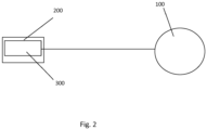
Figure 2 provides a schematic side view of an apparatus according to an example of the disclosure (not claimed). -
Figure 3 provides a schematic view of an apparatus according to one embodiment of the invention. -
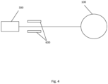
Figure 4 provides a schematic view of an apparatus according to an example of the disclosure (not claimed). - As used herein the term optically correct refers to an image which accurately portrays the interaction of visible electromagnetic radiation with a fibrous structure of particular optical properties.
- As used herein the term color correct refers to an image which accurately portrays a fibrous structure of particular optical properties illuminated by a visible electromagnetic radiation source having a particular emissive spectrum.
- As used herein the term fibrous structure refers to any structure comprised of discrete strands or fibers. These fibers may be artificial or natural fibers. In particular the term may be used to refer to an array of strands of keratinous materials. Keratinous fibers may be selected from wool, fur, silk, hair and mixtures thereof; preferably from mammalian hair; more preferably from human hair. Hair may be living hair i.e. on a living body or non-living hair i.e. in a wig, hairpiece or other aggregation of non-living keratinous fibers. Hair may be from Caucasian, Asian, African, Afro-Caribbean origins or combinations of these ethnic types. Hair may be selected from non-treated hair (i.e. virgin hair), treated hair and mixtures thereof. Treated hair may be selected from artificially-colored hair, bleached hair, permanently-waved hair, and mixtures thereof.
- These fibers may have an average diameter from about 10 to about 200 microns, preferably from about 30 to about 150 microns, more preferably about 50 to about 120 microns.
- In an example (not claimed), illustrated in
Figures 1 and2 , an apparatus for determining material optical properties comprises: a material holder comprising acurvilinear surface 100; a collimatedlight source 200 disposed in alignment with a surface normal of thecurvilinear surface 100. The light source provided illuminates thematerial holder 100. The apparatus further comprises animage capture element 300 aligned with the collimatedlight source 200 and the surface normal of the curvilinear surface of thematerial holder 100, an angular offset between an axis of thecollimated light source 200 and an axis of theimage capture element 300, each in the same plane of a surface normal of the curvilinear surface of thematerial holder 100, less than about 5 degrees. In one embodiment, the offset between the two axes is less than about 3 degrees. In one embodiment, either the image capture element or the illumination source is disposed such that its axis is normal to the curvilinear surface of the material holder, with the other axis disposed at an angular offset as described above. Alternatively, each of the two axes may be disposed about half of the maximum angular offset from being normal to the curvilinear surface of the material holder. As an example, each of the two axes may be disposed about 2.5 degrees from normal to the curvilinear surface. The divergence angle of the collimated light may be less than about 0.5 degrees. The luminance of the light source in the area where the target material is mounted should not vary by more than 5% of the average luminance in this area. - In one embodiment, the image capture element and illumination source are each aligned to within about 5 degrees, preferably within about 1 degree, more preferably within about 0.2 degrees, of an imaginary plane including a surface normal of the curvilinear surface of the material holder.
-
Figure 3 illustrate an embodiment wherein the collimatedlight source 200 is disposed with its axis parallel to, but not otherwise aligned with, the axis of theimage capture element 300.Surface mirror 400 and halfsilvered mirror 500 are disposed to bring the output of the collimatedlight source 200 into alignment with the axis of the image capture element and to illuminate theimage capture surface 100. A beam splitter may be substituted for the halfsilvered mirror 500. -
Figure 4 illustrates an example (not claimed) wherein aring light 600 is disposed such that the axis of illumination of thering light 600 is aligned with the axis of theimage capture element 300. - In one embodiment, a Xenon High Pressure light source may be used to illuminate the material and material holder. The 150W Xenon are lamp Model: 6255 Oriel Instruments available from LOT Quantum Design GmbH (Germany) is an exemplary light source. The light source may be a D55 simulator. D55 corresponds roughly to midday sun light in Western Europe / Northern Europe; hence it is also called a daylight illuminant.
- The material holder may have a cylindrical cross section or other cross section comprising at least a curvilinear portion disposed facing the illumination source and the image capture clement. The material holder may be fabricated from any suitable material including wood, metal, glass, polymers, or composite materials. The material holder may comprise a comb or other fiber separating element to enable the material sample to be arrayed upon the material holder with the fibers separated and aligned upon the curvilinear surface.
- The image capture clement may comprise a high dynamic range digital camera. An exemplary image capture element, a camera, is the TXG50c available from the Baumer Group, of Frauenfeld, Switzerland, and having a dynamic range of 12 bits for each of the Red, Green and Blue channels is an exemplary image capture element. A digital camera of lower dynamic range may be used as the image capture element providing that multiple images at different exposures are captured and combined.
- The sample of fibrous structure may comprise fibrous structures as defined hereinabove. This sample may comprise from about 2 to about 10000, preferably from about 10 to about 5000, more preferably from about 100 to about 2000, fibrous structures.
- In practice, a sample of fibrous material, such as hair, is disposed in an aligned array upon the curvilinear surface of the material holder. The arrayed fibers may be disposed in multiple layers upon the surface or in a single layer. The aligned disposition may be made easier through the utilization of a fiber separating element. The disposed array of fibers may be illuminated using the collimated D55 illumination source. The 6255 Xenon Lamp, available from Oriel Instruments, available from LOT Quantum Design GmbH (Germany), is an exemplary illumination source. At least one digital image of the illuminated fiber sample is captured for analysis, though more than one image may be captured. In one embodiment, the captured digital image is a high resolution image. The angular relationship between the image capture element, the illumination source and the material holder may be as described above.
- The capture image may be analyzed using software from GfaR, available from Dr. Arno Zinke, to determine values for intensity of RGB signals along columns of the image.
- The captured image may be corrected to reduce the effects produced by the angular offset between the illumination source and the image capture element. In one embodiment, this image correction may be accomplished utilizing the GfaR software developed by Dr. Amo Zinke, GfaR, GmbH, Bonn, Germany.
- The image may be smoothed by calculating an average value for each row of pixels in the image and subsequently altering the value of each pixel as necessary to reduce the difference between the value of the particular pixel and the average value for the row of pixels.
- Optical fingerprint parameters (OFP) including: Absorption red (radius (hair fiber)^-1), Absorption green (radius (hair fiber)^-1), Absorption blue (radius (hair fiber)^-1), long Shift R ( Degrees), long Shift TT (Degrees), long Shift TRT ( Degree), long Width R (Degrees), long Width TT ( Degrees), long Width TRT (Degrees), Scale R (no units), diffuse Fraction (no units), diffuse Reflectance red (no units), diffuse Reflectance green (no units), and diffuse Reflectance blue (no units), are defined for the image. As used in the previous sentence, the term "R" means "Reflection (on the outer surface)", "TT" means "2x Transmission (no reflection back towards the light source)" and "TRT" means "Transmission, Reflection, Transmission (reflection on the inner back side)". The values of the parameters are calculated using algorithms developed by Dr. Zinke, to estimate a bi-directional reflectance distribution function (BRDF) and to determine a bi-directional curve scattering distribution function, (BCSDF) using the GfaR software.
- The calculation is performed iteratively to reduce the error between an image rendered virtually using the parameters and the initial image of the fibrous material to a minimum value.
- Images of virtual fibrous materials may subsequently be created using the calculated OFP by using the OFP values together with a virtual model of a fibrous structure, a virtual illumination source of a particular luminosity and spectrum, arranged in a particular location relative to the virtual model and calculating the appearance of the fibrous structure according to the interaction of the parametric fibrous material properties and the parametric virtual light environment. The creation of the images may be accomplished via monte carlo path tracing and may take into consideration the definition of the light source in terms of its distance from the object, the size and distribution of the luminance and the angular distribution of the outgoing rays, the definition of the position and orientation of the hair model, and the definition and position and orientation of the camera.
- OFF values in following ranges have been found to yield acceptable representations of fibrous structures when compared to actual images of underlying fibrous structures: Absorption r 0,00805 to 2,96; Absorption g 0,018365 to 2,9613, Absorption b 0,031964 to 2,984, long Shift R (-8,3837) to (-0,9615), long Shift TT (-0,33319) to (3,8045), long Shift TRT (-0,99956) to 11,4136, long Width R 1,4976 to 12,4241, long Width TT 1,6076 to 15,3835, long Width TRT 4,1421 to 35,5172, Scale R 0,60002 to 0,99999, diffuse Fraction 0,00225 to 0,28391, diffuse Reflectance r 0,20935 to 1,124, diffuse Reflectance g 0,083714 to 1,0391, and diffuse Reflectance b 0,013692 to 1,0381.
- The dimensions and values disclosed herein are not to be understood as being strictly limited to the exact numerical values recited. Instead, unless otherwise specified, each such dimension is intended to mean both the recited value and a functionally equivalent range surrounding that value. For example, a dimension disclosed as "40 mm" is intended to mean "about 40 mm."
- Every document cited herein, including any cross referenced or related patent or application, is hereby incorporated herein by reference in its entirety unless expressly excluded or otherwise limited. The citation of any document is not an admission that it is prior art with respect to any invention disclosed or claimed herein or that it alone, or in any combination with any other reference or references, teaches, suggests or discloses any such invention. Further, to the extent that any meaning or definition of a term in this document conflicts with any meaning or definition of the same term in a document incorporated by reference, the meaning or definition assigned to that term in this document shall govern.
- While particular embodiments of the present invention have been illustrated and described, it would be obvious to those skilled in the art that various other changes and modifications can be made without departing from the scope of the invention as defined in the appended claims.
Claims (3)
- An apparatus for determining material optical properties of hair, the apparatus comprising:a. a material holder (100) for a sample of hair, comprising a curvilinear surface;b. a light source (200) to illuminate the material holder (100); andc. an image capture element (300) aligned with the surface normal of the curvilinear surface of the material holder (100);wherein the light source (200) has an output; andwherein the light source (200) is disposed with its axis parallel to, but not otherwise aligned with, the axis of the image capture element (300),characterised in that said light source is a collimated light source and in that a surface mirror (400) and a half silvered mirror (500) are disposed to bring the output of the collimated light source (200) into alignment with the axis of the image capture element (300) and to illuminate the curvilinear surface.
- The apparatus according to claim 1 wherein the material holder (100) further comprises a fiber separator.
- A method for defining material optical properties of hair, the method comprising steps of:a. disposing a sample of the hair upon a material holder (100) comprising a curvilinear surface;b. illuminating the disposed sample with a collimated light source (200) disposed in alignment with a surface normal of the curvilinear surface, to illuminate the material holder (100);c. capturing at least one digital image of the disposed hair sample using an image capture element (300) aligned with the collimated light source (200) and the surface normal of the curvilinear surface of the material holder (100), wherein an angular offset between an axis of the collimated light source (200) and an axis of the image capture element (300), each in a plane of the surface normal of the curvilinear surface of the material holder (100), is less than about 5 degrees;d. correcting the captured image according to the angular offset to reduce the effects produced by the angular offset between the collimated light source (200) and the image capture element (300);e. replacing erroneous pixels in the captured image with non-erroneous pixels to reduce the effect of misaligned hair; andf. defining parameters according to an optimized fit between a modeled image of hair and the captured image of hair.
Priority Applications (6)
| Application Number | Priority Date | Filing Date | Title |
|---|---|---|---|
| EP13184818.6A EP2848919B1 (en) | 2013-09-17 | 2013-09-17 | Method and apparatus for creating images of fibrous structures |
| MX2016003281A MX2016003281A (en) | 2013-09-17 | 2014-09-10 | Method and apparatus for creating images of fibrous structures. |
| BR112016005867A BR112016005867A2 (en) | 2013-09-17 | 2014-09-10 | method and apparatus for imaging fibrous structures |
| JP2016543928A JP2016533506A (en) | 2013-09-17 | 2014-09-10 | Method and apparatus for creating an image of a fibrous structure |
| PCT/US2014/054872 WO2015041903A1 (en) | 2013-09-17 | 2014-09-10 | Method and apparatus for creating images of fibrous structures |
| US14/488,966 US9563942B2 (en) | 2013-09-17 | 2014-09-17 | Method and apparatus for creating images of fibrous structures |
Applications Claiming Priority (1)
| Application Number | Priority Date | Filing Date | Title |
|---|---|---|---|
| EP13184818.6A EP2848919B1 (en) | 2013-09-17 | 2013-09-17 | Method and apparatus for creating images of fibrous structures |
Publications (2)
| Publication Number | Publication Date |
|---|---|
| EP2848919A1 EP2848919A1 (en) | 2015-03-18 |
| EP2848919B1 true EP2848919B1 (en) | 2024-11-13 |
Family
ID=49237031
Family Applications (1)
| Application Number | Title | Priority Date | Filing Date |
|---|---|---|---|
| EP13184818.6A Active EP2848919B1 (en) | 2013-09-17 | 2013-09-17 | Method and apparatus for creating images of fibrous structures |
Country Status (6)
| Country | Link |
|---|---|
| US (1) | US9563942B2 (en) |
| EP (1) | EP2848919B1 (en) |
| JP (1) | JP2016533506A (en) |
| BR (1) | BR112016005867A2 (en) |
| MX (1) | MX2016003281A (en) |
| WO (1) | WO2015041903A1 (en) |
Families Citing this family (1)
| Publication number | Priority date | Publication date | Assignee | Title |
|---|---|---|---|---|
| CN110290323B (en) * | 2019-06-28 | 2021-09-07 | Oppo广东移动通信有限公司 | Image processing method, apparatus, electronic device, and computer-readable storage medium |
Citations (2)
| Publication number | Priority date | Publication date | Assignee | Title |
|---|---|---|---|---|
| JP2000206043A (en) * | 1999-01-12 | 2000-07-28 | Kao Corp | Hair quality evaluation device |
| US20120140230A1 (en) * | 2009-08-13 | 2012-06-07 | Siemens Healthcare Diagnostics Inc. | Methods And Apparatus For Ascertaining Interferents And Physical Dimensions In Liquid Samples And Containers To Be Analyzed By A Clinical Analyzer |
Family Cites Families (6)
| Publication number | Priority date | Publication date | Assignee | Title |
|---|---|---|---|---|
| US6738659B2 (en) * | 2000-08-31 | 2004-05-18 | Hsu Pei-Feng | Optical imaging using the temporal direct reflective signal from a minimized pulse width laser |
| JP2005038021A (en) * | 2003-07-15 | 2005-02-10 | Ricoh Co Ltd | Image processing apparatus, image input apparatus, image processing method, and program for executing image processing method on computer |
| JP2006024141A (en) * | 2004-07-09 | 2006-01-26 | Sony Corp | Image processing apparatus and method, and program |
| EP1653219A1 (en) * | 2004-10-26 | 2006-05-03 | The Procter & Gamble Company | Method and apparatus for examining human hairs |
| US7495758B2 (en) * | 2006-09-06 | 2009-02-24 | Theo Boeing Company | Apparatus and methods for two-dimensional and three-dimensional inspection of a workpiece |
| US8391639B2 (en) * | 2007-07-23 | 2013-03-05 | The Procter & Gamble Company | Method and apparatus for realistic simulation of wrinkle aging and de-aging |
-
2013
- 2013-09-17 EP EP13184818.6A patent/EP2848919B1/en active Active
-
2014
- 2014-09-10 MX MX2016003281A patent/MX2016003281A/en unknown
- 2014-09-10 JP JP2016543928A patent/JP2016533506A/en active Pending
- 2014-09-10 BR BR112016005867A patent/BR112016005867A2/en not_active Application Discontinuation
- 2014-09-10 WO PCT/US2014/054872 patent/WO2015041903A1/en not_active Ceased
- 2014-09-17 US US14/488,966 patent/US9563942B2/en not_active Expired - Fee Related
Patent Citations (2)
| Publication number | Priority date | Publication date | Assignee | Title |
|---|---|---|---|---|
| JP2000206043A (en) * | 1999-01-12 | 2000-07-28 | Kao Corp | Hair quality evaluation device |
| US20120140230A1 (en) * | 2009-08-13 | 2012-06-07 | Siemens Healthcare Diagnostics Inc. | Methods And Apparatus For Ascertaining Interferents And Physical Dimensions In Liquid Samples And Containers To Be Analyzed By A Clinical Analyzer |
Non-Patent Citations (1)
| Title |
|---|
| R LU ET AL: "Optical properties (bidirectional reflection distribution functions) of velvet", APPLIED OPTICS, 1 September 1998 (1998-09-01), pages 5974, XP055731545, Retrieved from the Internet <URL:https://www.osapublishing.org/DirectPDFAccess/12FBB303-E7FC-7FB1-A4BE75B354D44F7E_43793/ao-37-25-5974.pdf?da=1&id=43793&seq=0&mobile=no> [retrieved on 20200922], DOI: 10.1364/AO.37.005974 * |
Also Published As
| Publication number | Publication date |
|---|---|
| BR112016005867A2 (en) | 2017-08-01 |
| JP2016533506A (en) | 2016-10-27 |
| MX2016003281A (en) | 2016-06-24 |
| US20150077533A1 (en) | 2015-03-19 |
| EP2848919A1 (en) | 2015-03-18 |
| US9563942B2 (en) | 2017-02-07 |
| WO2015041903A1 (en) | 2015-03-26 |
Similar Documents
| Publication | Publication Date | Title |
|---|---|---|
| CN104823213B (en) | Camera system, the color conversion apparatus used in it and the storage medium of method and color converting procedure | |
| CN102327156B (en) | Dental shade mapping | |
| CN101904773B (en) | Apparatus for dental surface shape and shade imaging | |
| US6907138B1 (en) | Method and device for analyzing surface structure | |
| KR102343251B1 (en) | A method for selecting a cosmetic product for an intended user | |
| US7480035B2 (en) | Glare-directed imaging | |
| EP2202688A3 (en) | System, method and apparatus for image processing and image format | |
| EP3701330B1 (en) | System and method for optical inspection of an object | |
| Caglar et al. | Could digital imaging be an alternative for digital colorimeters? | |
| US20200060798A1 (en) | Color Selection Aid For Target Objects Such As Dental Objects | |
| Dekker et al. | Spatial analysis of the ancient proteome of archeological teeth using mass spectrometry imaging | |
| US9563942B2 (en) | Method and apparatus for creating images of fibrous structures | |
| Nantanapiboon et al. | Impact of different lighting conditions on the tooth-shade selection using intra-oral scanners: An in-vitro study | |
| KR20080008993A (en) | How to Make Dental Colorimeters and Dental Prosthetics Hues | |
| EP2739206B1 (en) | Adaptive illumination method and apparatus for dental shade matching | |
| Szabó et al. | Optical analysis of Müller glia cells as light transporters through the retina | |
| CN103245307B (en) | A kind of detection method being suitable for mensuration cigarette tipping paper stamping area | |
| JP6823368B2 (en) | Irradiation support device, face photography device, and skin evaluation method | |
| JPWO2019124449A1 (en) | Visual function inspection and optical characteristic calculation system | |
| JP2019027886A (en) | Radiation characteristic measurement system and radiation characteristic measurement method | |
| Mangkuto et al. | Optimisation of luminance-based metrics for lighting in an open-plan dental examination room considering psycho-physiological response of dentists | |
| Guevara et al. | Light Scatter in Optical Materials: Advanced Haze Modeling | |
| Miccoli et al. | Modular wide spectrum lighting system for diagnosis, conservation, and restoration | |
| Iacomussi et al. | The shroud of Turin: spectral and colorimetric analysis for innovative lighting | |
| Gilchrist | Current problems in lightness theory |
Legal Events
| Date | Code | Title | Description |
|---|---|---|---|
| PUAI | Public reference made under article 153(3) epc to a published international application that has entered the european phase |
Free format text: ORIGINAL CODE: 0009012 |
|
| 17P | Request for examination filed |
Effective date: 20130917 |
|
| AK | Designated contracting states |
Kind code of ref document: A1 Designated state(s): AL AT BE BG CH CY CZ DE DK EE ES FI FR GB GR HR HU IE IS IT LI LT LU LV MC MK MT NL NO PL PT RO RS SE SI SK SM TR |
|
| AX | Request for extension of the european patent |
Extension state: BA ME |
|
| R17P | Request for examination filed (corrected) |
Effective date: 20150527 |
|
| RBV | Designated contracting states (corrected) |
Designated state(s): AL AT BE BG CH CY CZ DE DK EE ES FI FR GB GR HR HU IE IS IT LI LT LU LV MC MK MT NL NO PL PT RO RS SE SI SK SM TR |
|
| RAP1 | Party data changed (applicant data changed or rights of an application transferred) |
Owner name: NOXELL CORPORATION |
|
| STAA | Information on the status of an ep patent application or granted ep patent |
Free format text: STATUS: EXAMINATION IS IN PROGRESS |
|
| 17Q | First examination report despatched |
Effective date: 20200929 |
|
| RAP1 | Party data changed (applicant data changed or rights of an application transferred) |
Owner name: WELLA OPERATIONS US, LLC |
|
| GRAP | Despatch of communication of intention to grant a patent |
Free format text: ORIGINAL CODE: EPIDOSNIGR1 |
|
| STAA | Information on the status of an ep patent application or granted ep patent |
Free format text: STATUS: GRANT OF PATENT IS INTENDED |
|
| INTG | Intention to grant announced |
Effective date: 20240621 |
|
| GRAS | Grant fee paid |
Free format text: ORIGINAL CODE: EPIDOSNIGR3 |
|
| GRAA | (expected) grant |
Free format text: ORIGINAL CODE: 0009210 |
|
| STAA | Information on the status of an ep patent application or granted ep patent |
Free format text: STATUS: THE PATENT HAS BEEN GRANTED |
|
| AK | Designated contracting states |
Kind code of ref document: B1 Designated state(s): AL AT BE BG CH CY CZ DE DK EE ES FI FR GB GR HR HU IE IS IT LI LT LU LV MC MK MT NL NO PL PT RO RS SE SI SK SM TR |
|
| REG | Reference to a national code |
Ref country code: GB Ref legal event code: FG4D |
|
| REG | Reference to a national code |
Ref country code: CH Ref legal event code: EP |
|
| REG | Reference to a national code |
Ref country code: DE Ref legal event code: R096 Ref document number: 602013086287 Country of ref document: DE |
|
| REG | Reference to a national code |
Ref country code: IE Ref legal event code: FG4D |
|
| REG | Reference to a national code |
Ref country code: LT Ref legal event code: MG9D |
|
| REG | Reference to a national code |
Ref country code: NL Ref legal event code: MP Effective date: 20241113 |
|
| PG25 | Lapsed in a contracting state [announced via postgrant information from national office to epo] |
Ref country code: HR Free format text: LAPSE BECAUSE OF FAILURE TO SUBMIT A TRANSLATION OF THE DESCRIPTION OR TO PAY THE FEE WITHIN THE PRESCRIBED TIME-LIMIT Effective date: 20241113 Ref country code: IS Free format text: LAPSE BECAUSE OF FAILURE TO SUBMIT A TRANSLATION OF THE DESCRIPTION OR TO PAY THE FEE WITHIN THE PRESCRIBED TIME-LIMIT Effective date: 20250313 Ref country code: PT Free format text: LAPSE BECAUSE OF FAILURE TO SUBMIT A TRANSLATION OF THE DESCRIPTION OR TO PAY THE FEE WITHIN THE PRESCRIBED TIME-LIMIT Effective date: 20250313 |
|
| PG25 | Lapsed in a contracting state [announced via postgrant information from national office to epo] |
Ref country code: NL Free format text: LAPSE BECAUSE OF FAILURE TO SUBMIT A TRANSLATION OF THE DESCRIPTION OR TO PAY THE FEE WITHIN THE PRESCRIBED TIME-LIMIT Effective date: 20241113 Ref country code: FI Free format text: LAPSE BECAUSE OF FAILURE TO SUBMIT A TRANSLATION OF THE DESCRIPTION OR TO PAY THE FEE WITHIN THE PRESCRIBED TIME-LIMIT Effective date: 20241113 |
|
| REG | Reference to a national code |
Ref country code: AT Ref legal event code: MK05 Ref document number: 1742016 Country of ref document: AT Kind code of ref document: T Effective date: 20241113 |
|
| PG25 | Lapsed in a contracting state [announced via postgrant information from national office to epo] |
Ref country code: BG Free format text: LAPSE BECAUSE OF FAILURE TO SUBMIT A TRANSLATION OF THE DESCRIPTION OR TO PAY THE FEE WITHIN THE PRESCRIBED TIME-LIMIT Effective date: 20241113 |
|
| PG25 | Lapsed in a contracting state [announced via postgrant information from national office to epo] |
Ref country code: ES Free format text: LAPSE BECAUSE OF FAILURE TO SUBMIT A TRANSLATION OF THE DESCRIPTION OR TO PAY THE FEE WITHIN THE PRESCRIBED TIME-LIMIT Effective date: 20241113 |
|
| PG25 | Lapsed in a contracting state [announced via postgrant information from national office to epo] |
Ref country code: NO Free format text: LAPSE BECAUSE OF FAILURE TO SUBMIT A TRANSLATION OF THE DESCRIPTION OR TO PAY THE FEE WITHIN THE PRESCRIBED TIME-LIMIT Effective date: 20250213 |
|
| PG25 | Lapsed in a contracting state [announced via postgrant information from national office to epo] |
Ref country code: LV Free format text: LAPSE BECAUSE OF FAILURE TO SUBMIT A TRANSLATION OF THE DESCRIPTION OR TO PAY THE FEE WITHIN THE PRESCRIBED TIME-LIMIT Effective date: 20241113 Ref country code: GR Free format text: LAPSE BECAUSE OF FAILURE TO SUBMIT A TRANSLATION OF THE DESCRIPTION OR TO PAY THE FEE WITHIN THE PRESCRIBED TIME-LIMIT Effective date: 20250214 Ref country code: AT Free format text: LAPSE BECAUSE OF FAILURE TO SUBMIT A TRANSLATION OF THE DESCRIPTION OR TO PAY THE FEE WITHIN THE PRESCRIBED TIME-LIMIT Effective date: 20241113 |
|
| PG25 | Lapsed in a contracting state [announced via postgrant information from national office to epo] |
Ref country code: PL Free format text: LAPSE BECAUSE OF FAILURE TO SUBMIT A TRANSLATION OF THE DESCRIPTION OR TO PAY THE FEE WITHIN THE PRESCRIBED TIME-LIMIT Effective date: 20241113 |
|
| PG25 | Lapsed in a contracting state [announced via postgrant information from national office to epo] |
Ref country code: RS Free format text: LAPSE BECAUSE OF FAILURE TO SUBMIT A TRANSLATION OF THE DESCRIPTION OR TO PAY THE FEE WITHIN THE PRESCRIBED TIME-LIMIT Effective date: 20250213 |
|
| PG25 | Lapsed in a contracting state [announced via postgrant information from national office to epo] |
Ref country code: SM Free format text: LAPSE BECAUSE OF FAILURE TO SUBMIT A TRANSLATION OF THE DESCRIPTION OR TO PAY THE FEE WITHIN THE PRESCRIBED TIME-LIMIT Effective date: 20241113 |
|
| PG25 | Lapsed in a contracting state [announced via postgrant information from national office to epo] |
Ref country code: DK Free format text: LAPSE BECAUSE OF FAILURE TO SUBMIT A TRANSLATION OF THE DESCRIPTION OR TO PAY THE FEE WITHIN THE PRESCRIBED TIME-LIMIT Effective date: 20241113 |
|
| PG25 | Lapsed in a contracting state [announced via postgrant information from national office to epo] |
Ref country code: EE Free format text: LAPSE BECAUSE OF FAILURE TO SUBMIT A TRANSLATION OF THE DESCRIPTION OR TO PAY THE FEE WITHIN THE PRESCRIBED TIME-LIMIT Effective date: 20241113 |
|
| PG25 | Lapsed in a contracting state [announced via postgrant information from national office to epo] |
Ref country code: RO Free format text: LAPSE BECAUSE OF FAILURE TO SUBMIT A TRANSLATION OF THE DESCRIPTION OR TO PAY THE FEE WITHIN THE PRESCRIBED TIME-LIMIT Effective date: 20241113 |
|
| PG25 | Lapsed in a contracting state [announced via postgrant information from national office to epo] |
Ref country code: SK Free format text: LAPSE BECAUSE OF FAILURE TO SUBMIT A TRANSLATION OF THE DESCRIPTION OR TO PAY THE FEE WITHIN THE PRESCRIBED TIME-LIMIT Effective date: 20241113 |
|
| PG25 | Lapsed in a contracting state [announced via postgrant information from national office to epo] |
Ref country code: CZ Free format text: LAPSE BECAUSE OF FAILURE TO SUBMIT A TRANSLATION OF THE DESCRIPTION OR TO PAY THE FEE WITHIN THE PRESCRIBED TIME-LIMIT Effective date: 20241113 |
|
| PG25 | Lapsed in a contracting state [announced via postgrant information from national office to epo] |
Ref country code: IT Free format text: LAPSE BECAUSE OF FAILURE TO SUBMIT A TRANSLATION OF THE DESCRIPTION OR TO PAY THE FEE WITHIN THE PRESCRIBED TIME-LIMIT Effective date: 20241113 |
|
| REG | Reference to a national code |
Ref country code: DE Ref legal event code: R097 Ref document number: 602013086287 Country of ref document: DE |
|
| PG25 | Lapsed in a contracting state [announced via postgrant information from national office to epo] |
Ref country code: SE Free format text: LAPSE BECAUSE OF FAILURE TO SUBMIT A TRANSLATION OF THE DESCRIPTION OR TO PAY THE FEE WITHIN THE PRESCRIBED TIME-LIMIT Effective date: 20241113 |
|
| PLBE | No opposition filed within time limit |
Free format text: ORIGINAL CODE: 0009261 |
|
| STAA | Information on the status of an ep patent application or granted ep patent |
Free format text: STATUS: NO OPPOSITION FILED WITHIN TIME LIMIT |
|
| PGFP | Annual fee paid to national office [announced via postgrant information from national office to epo] |
Ref country code: DE Payment date: 20250919 Year of fee payment: 13 |
|
| PGFP | Annual fee paid to national office [announced via postgrant information from national office to epo] |
Ref country code: GB Payment date: 20250918 Year of fee payment: 13 |
|
| PGFP | Annual fee paid to national office [announced via postgrant information from national office to epo] |
Ref country code: FR Payment date: 20250922 Year of fee payment: 13 |
|
| 26N | No opposition filed |
Effective date: 20250814 |
|
| REG | Reference to a national code |
Ref country code: CH Ref legal event code: H13 Free format text: ST27 STATUS EVENT CODE: U-0-0-H10-H13 (AS PROVIDED BY THE NATIONAL OFFICE) Effective date: 20260504 |