EP2848781A1 - Internal combustion engine - Google Patents
Internal combustion engine Download PDFInfo
- Publication number
- EP2848781A1 EP2848781A1 EP12876521.1A EP12876521A EP2848781A1 EP 2848781 A1 EP2848781 A1 EP 2848781A1 EP 12876521 A EP12876521 A EP 12876521A EP 2848781 A1 EP2848781 A1 EP 2848781A1
- Authority
- EP
- European Patent Office
- Prior art keywords
- oil
- intake pipe
- gas
- tubular member
- pipe
- Prior art date
- Legal status (The legal status is an assumption and is not a legal conclusion. Google has not performed a legal analysis and makes no representation as to the accuracy of the status listed.)
- Withdrawn
Links
Images







Classifications
-
- F—MECHANICAL ENGINEERING; LIGHTING; HEATING; WEAPONS; BLASTING
- F01—MACHINES OR ENGINES IN GENERAL; ENGINE PLANTS IN GENERAL; STEAM ENGINES
- F01M—LUBRICATING OF MACHINES OR ENGINES IN GENERAL; LUBRICATING INTERNAL COMBUSTION ENGINES; CRANKCASE VENTILATING
- F01M13/00—Crankcase ventilating or breathing
- F01M13/04—Crankcase ventilating or breathing having means for purifying air before leaving crankcase, e.g. removing oil
-
- F—MECHANICAL ENGINEERING; LIGHTING; HEATING; WEAPONS; BLASTING
- F01—MACHINES OR ENGINES IN GENERAL; ENGINE PLANTS IN GENERAL; STEAM ENGINES
- F01M—LUBRICATING OF MACHINES OR ENGINES IN GENERAL; LUBRICATING INTERNAL COMBUSTION ENGINES; CRANKCASE VENTILATING
- F01M13/00—Crankcase ventilating or breathing
- F01M13/02—Crankcase ventilating or breathing by means of additional source of positive or negative pressure
- F01M13/028—Crankcase ventilating or breathing by means of additional source of positive or negative pressure of positive pressure
-
- F—MECHANICAL ENGINEERING; LIGHTING; HEATING; WEAPONS; BLASTING
- F02—COMBUSTION ENGINES; HOT-GAS OR COMBUSTION-PRODUCT ENGINE PLANTS
- F02M—SUPPLYING COMBUSTION ENGINES IN GENERAL WITH COMBUSTIBLE MIXTURES OR CONSTITUENTS THEREOF
- F02M35/00—Combustion-air cleaners, air intakes, intake silencers, or induction systems specially adapted for, or arranged on, internal-combustion engines
- F02M35/10—Air intakes; Induction systems
- F02M35/10209—Fluid connections to the air intake system; their arrangement of pipes, valves or the like
- F02M35/10222—Exhaust gas recirculation [EGR]; Positive crankcase ventilation [PCV]; Additional air admission, lubricant or fuel vapour admission
-
- F—MECHANICAL ENGINEERING; LIGHTING; HEATING; WEAPONS; BLASTING
- F04—POSITIVE - DISPLACEMENT MACHINES FOR LIQUIDS; PUMPS FOR LIQUIDS OR ELASTIC FLUIDS
- F04D—NON-POSITIVE-DISPLACEMENT PUMPS
- F04D17/00—Radial-flow pumps, e.g. centrifugal pumps; Helico-centrifugal pumps
- F04D17/08—Centrifugal pumps
- F04D17/10—Centrifugal pumps for compressing or evacuating
-
- F—MECHANICAL ENGINEERING; LIGHTING; HEATING; WEAPONS; BLASTING
- F04—POSITIVE - DISPLACEMENT MACHINES FOR LIQUIDS; PUMPS FOR LIQUIDS OR ELASTIC FLUIDS
- F04D—NON-POSITIVE-DISPLACEMENT PUMPS
- F04D29/00—Details, component parts, or accessories
- F04D29/26—Rotors specially for elastic fluids
- F04D29/28—Rotors specially for elastic fluids for centrifugal or helico-centrifugal pumps for radial-flow or helico-centrifugal pumps
- F04D29/284—Rotors specially for elastic fluids for centrifugal or helico-centrifugal pumps for radial-flow or helico-centrifugal pumps for compressors
-
- F—MECHANICAL ENGINEERING; LIGHTING; HEATING; WEAPONS; BLASTING
- F04—POSITIVE - DISPLACEMENT MACHINES FOR LIQUIDS; PUMPS FOR LIQUIDS OR ELASTIC FLUIDS
- F04D—NON-POSITIVE-DISPLACEMENT PUMPS
- F04D29/00—Details, component parts, or accessories
- F04D29/70—Suction grids; Strainers; Dust separation; Cleaning
- F04D29/701—Suction grids; Strainers; Dust separation; Cleaning especially adapted for elastic fluid pumps
-
- F—MECHANICAL ENGINEERING; LIGHTING; HEATING; WEAPONS; BLASTING
- F04—POSITIVE - DISPLACEMENT MACHINES FOR LIQUIDS; PUMPS FOR LIQUIDS OR ELASTIC FLUIDS
- F04D—NON-POSITIVE-DISPLACEMENT PUMPS
- F04D29/00—Details, component parts, or accessories
- F04D29/70—Suction grids; Strainers; Dust separation; Cleaning
- F04D29/701—Suction grids; Strainers; Dust separation; Cleaning especially adapted for elastic fluid pumps
- F04D29/705—Adding liquids
-
- F—MECHANICAL ENGINEERING; LIGHTING; HEATING; WEAPONS; BLASTING
- F01—MACHINES OR ENGINES IN GENERAL; ENGINE PLANTS IN GENERAL; STEAM ENGINES
- F01M—LUBRICATING OF MACHINES OR ENGINES IN GENERAL; LUBRICATING INTERNAL COMBUSTION ENGINES; CRANKCASE VENTILATING
- F01M13/00—Crankcase ventilating or breathing
- F01M13/02—Crankcase ventilating or breathing by means of additional source of positive or negative pressure
- F01M13/021—Crankcase ventilating or breathing by means of additional source of positive or negative pressure of negative pressure
- F01M2013/027—Crankcase ventilating or breathing by means of additional source of positive or negative pressure of negative pressure with a turbo charger or compressor
-
- F—MECHANICAL ENGINEERING; LIGHTING; HEATING; WEAPONS; BLASTING
- F01—MACHINES OR ENGINES IN GENERAL; ENGINE PLANTS IN GENERAL; STEAM ENGINES
- F01M—LUBRICATING OF MACHINES OR ENGINES IN GENERAL; LUBRICATING INTERNAL COMBUSTION ENGINES; CRANKCASE VENTILATING
- F01M13/00—Crankcase ventilating or breathing
- F01M13/04—Crankcase ventilating or breathing having means for purifying air before leaving crankcase, e.g. removing oil
- F01M2013/0422—Separating oil and gas with a centrifuge device
Definitions
- the present invention relates to an internal combustion engine, and more particularly relates to an internal combustion engine that is equipped with a blow-by gas returning mechanism.
- Patent Literature 1 discloses the blow-by gas returning mechanism that includes a first PCV pipe which connects a cylinder head and an intake pipe, at a downstream side from a throttle valve, and a second PCV pipe which connects the cylinder head and the intake pipe at an upstream side from a compressor.
- a blow-by gas is reintroduced into an internal combustion engine by two paths that are the first PCV pipe and the second PCV pipe and can be combusted.
- soot derived from carbon fuel, and oil in a crankcase are contained.
- Patent Literature 1 a removal device that removes the oil in a blow-by gas is provided in the second PCV pipe.
- the removal device even if the removal device is used, complete removal of the oil is difficult, and the soot-containing oil flows into the intake pipe.
- oil mist of a particle size equal to or smaller than 1 ⁇ m hereinafter, called "oil mist with a small particle size" is difficult to capture by the removing device, and has the property of being easily evaporated because of the small particle size in addition.
- soot-containing oil flows into the intake pipe as oil mist with a small particle size, and contacts and adheres to the intake pipe inner wall and the like, the soot-containing oil turns into deposits with a high probability.
- the soot-containing oil turns into deposits with a high probability.
- the present invention is made in the light of the aforementioned problem, and has an object to provide an internal combustion engine capable of restraining generation or accumulation of deposits derived from oil mist.
- a first aspect of the present invention is an internal combustion engine, comprising:
- a second aspect of the present invention is the internal combustion engine according to the first aspect, wherein the particle size enlargement oil flowing means comprises an intake pipe internal member having an outer circumferential wall in a curved shape that is disposed on a blow-by gas passage in which the blow-by gas introduced into the intake pipe flows, the PCV pipe is connected to the intake pipe from above in a vertical direction, and an opening of the PCV pipe to the intake pipe, and the outer circumferential wall are disposed to face each other.
- a third aspect of the present invention is the internal combustion engine according to the second aspect, further comprising:
- a fourth aspect of the present invention is the internal combustion engine according to the second or the third aspect, wherein flowability reducing means that reduces flowability on the outer circumferential wall, of the oil in the blow-by gas introduced into the intake pipe is provided at the outer circumferential wall.
- a fifth aspect of the present invention is the internal combustion engine according to the fourth aspect, wherein the flowability reducing means is a plurality of means that extends in an upstream and downstream directions of the intake pipe, and are spaced from one another in a circumferential direction of the outer circumferential wall.
- a sixth aspect of the present invention is the internal combustion engine according to any one of the second to the fifth aspects, further comprising:
- the oil in the blow-by gas can be caused to flow along the inner circumferential wall of the intake pipe while the particle size of the oil is enlarged.
- the oil mist in the blow-by gas is increased in viscosity by losing the oil component inside the oil mist, and easily adheres to the intake pipe inner wall and the like at the time of contacting the intake pipe inner wall and the like.
- the particle size of the oil can be enlarged by the particle size enlargement oil flowing means, the viscosity increasing speed can be slowed down. Accordingly, adherence of the oil mist to the intake pipe inner wall and the like can be restrained. Consequently, according to the first invention, deposit generation can be restrained.
- the oil with an enlarged particle size in which the oil particle size is enlarged can take the oil with a small particle size inside the oil with an enlarged particle size. Therefore, if the oil with an enlarged particle size flows along the inner circumferential wall of the intake pipe, the oil with an enlarged particle size can uniformly wash and remove the oil which adheres to and is being deposited on a midpoint in the passage. Consequently, according to the first invention, accumulation of the deposits also can be restrained.
- the intake pipe internal member having the outer circumferential wall in a curved shape is disposed on the blow-by gas passage, and therefore, the blow-by gas can be caused to flow along the outer circumferential wall.
- the PCV pipe is connected to the above described intake pipe from above in the vertical direction, and further, the opening of the PCV pipe to the intake pipe, and the above described outer circumferential wall are disposed to face each other. Therefore, the above described oil with an enlarged particle size is generated on the above described outer circumferential wall, and can be caused to flow uniformly along the above described outer circumferential wall in accordance with the flow of the blow-by gas and the gravity.
- the blow-by gas is compressed by the compressor. Therefore, the inside of the above described compressor can be said to be under the environment where the viscosity of the oil mist in the blow-by gas is easily increased.
- the intake pipe internal member having the outer circumferential wall in a curved shape is disposed on the above described blow-by gas passage at the upstream side from the compressor, and therefore, the oil with an enlarged particle size in which the oil particle size is enlarged is caused to flow uniformly along the above described outer circumferential wall and can be introduced into the above described compressor. Accordingly, generation and accumulation of deposits inside the compressor can be restrained.
- the flowability reducing means by the flowability reducing means, flowability of the oil on the above described outer circumferential wall can be reduced. If the flowability of the oil can be reduced, enlargement of the particle size of the oil particle can be promoted before contact to the intake pipe inner wall and the like. Consequently, according to the present invention, the oil particle size can be reliably enlarged.
- the above described oil with an enlarged particle size flows along the above described outer circumferential wall in accordance with the flow of the blow-by gas and the gravity.
- the above described flowability reducing means corresponds to a plurality of means which extend in the upstream and downstream directions of the above described intake pipe, and are spaced from one another along the above described outer circumferential wall, and therefore, mobility of the blow-by gas in the flow direction and mobility of the blow-by gas in the vertical direction can be balanced. Accordingly, the above described oil with an enlarged particle size can be caused to flow more uniformly along the above described outer circumferential wall.
- the EGR gas is introduced into the above described intake pipe from the upstream side from the blow-by gas.
- the EGR gas is a high-temperature gas, and therefore, if the EGR gas mixes with the blow-by gas, the oil mist in the blow-by gas easily increases in viscosity.
- the upstream end opening of the internal piping with a smaller diameter than the intake pipe is opened toward the opening of the EGR pipe to the intake pipe, and therefore, the EGR gas can be introduced into the above described internal piping. Accordingly, the EGR gas and the blow-by gas can be prevented from mixing with each other, and therefore, increase in the viscosity of the oil mist can be prevented.
- FIG. 1 is a diagram for explaining a system configuration of embodiment 1.
- a system of the present embodiment includes an engine 10 as an internal combustion engine.
- Each of cylinders of the engine 10 is provided with a piston, an intake valve, an exhaust valve, fuel injector and the like. Note that the number of cylinders and disposition of the cylinders of the engine 10 are not specially limited.
- the system of the present embodiment includes a turbocharger 12.
- the turbocharger 12 includes a turbine 12a provided at an exhaust pipe 14, and a compressor 12b provided at an intake pipe 16.
- the turbine 12a and the compressor 12b are connected to each other.
- the turbine 12a receives an exhaust pressure and rotates, whereby the compressor 12b is driven, and a gas flowing into the compressor 12b is compressed.
- the intake pipe 16 is provided with an intercooler 18 that cools the compressed gas.
- the system of the present embodiment includes a blow-by gas returning mechanism which returns a blow-by gas.
- a blow-by gas is a gas that flows into a crankcase from a gap between the piston and a cylinder wall surface of the engine 10.
- the blow-by gas returning mechanism includes a PCV pipe 20.
- the PCV pipe 20 connects the intake pipe 16 at an upstream side from the compressor 12b and a cylinder head cover (not illustrated) of the engine 10.
- the blow-by gas flows in the PCV pipe 20 and the intake pipe 16 in this sequence, and thereby is reintroduced into the engine 10.
- Figure 2 is an enlarged sectional view of a vicinity of the compressor 12b in Figure 1 .
- the compressor 12b includes an impeller 22, a housing 24 and a connecting shaft 26.
- the housing 24 rotatably supports the connecting shaft 26 which supports the impeller 22 to be incapable of rotating.
- the housing 24 is provided with an inlet section 28 that introduces intake air to an intake side 22a of the impeller 22, a spiral scroll 30 that is disposed on an outer periphery of the impeller 22, and a diffuser 32 that allows a discharge side 22b of the impeller 22 and the scroll 30 to communicate with each other.
- the connecting shaft 26 is connected to a turbine wheel (not illustrated) of the turbine 12a.
- a tubular member 34 is disposed inside the intake pipe 16.
- the tubular member 34 and the intake pipe 16 are disposed in such a manner that center axes thereof correspond to each other. Thereby, a gap 36 is formed between the tubular member 34 and the intake pipe 16.
- a tubular member with an outside diameter thereof having a size of 85% to approximately 99% of an inside diameter of the intake pipe 16 is preferably used as the tubular member 34.
- Use of the tubular member 34 of the size like this would be preferable, because oil droplets (described later) are easily caused to flow along an outer circumferential wall of the tubular member 34.
- a downstream end 34a of the tubular member 34 is disposed to face the inlet section 28.
- FIG. 3 is an enlarged sectional view of the vicinity of the compressor 12b in Figure 1 .
- the blow-by gas which flows into the intake pipe 16 from the PCV pipe 20 flows to the inlet section 28 side together with an intake gas that flows in the gap 36.
- the blow-by gas collides with the outer circumferential wall of the tubular member 34, and thereafter, flows in such a manner as to be along the outer circumferential wall (an inner circumferential wall of the intake pipe 16) of the tubular member 34.
- oil mist that is a result of the oil in the crankcase being turned into mist is contained in the blow-by gas.
- the oil mist mentioned here is oil of a particle size equal to or smaller than approximately 5 ⁇ m.
- FIG. 4 is a sectional view taken along line A-A in Figure 3 .
- the PCV pipe 20 is connected to the intake pipe 16 from above in the gravitation direction (namely, above in the vertical direction). Therefore, the oil droplet 38 which is generated by collision of the blow-by gas flows down on the outer circumferential wall of the tubular member 34 in accordance with the gravity, and diffuses to the entire outer circumferential wall while keeping the liquefied state.
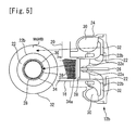
- Figure 5 is a view for explaining the behavior of the oil droplet 38 inside the compressor 12b.
- the oil droplet 38 diffuses to the entire outer circumferential wall of the tubular member 34 while keeping the liquefied state. Therefore, the oil droplet 38 flows in from the inlet section 28 while keeping the liquefied state, and flows uniformly into a surface of the impeller 22 to be discharged to the scroll 30 side. Consequently, according to the intake system structure of Figure 2 , the surface of the diffuser 32 is washed uniformly by the oil droplet 38 which keeps the liquefied state, and generation or accumulation of deposits on the surface can be restrained.
- FIG. 6 is a diagram for explaining the generation mechanism of a deposit.
- the oil in the crankcase is contained in the blow-by gas.
- a lot of oil mist is contained in the oil. This is because the blow-by gas immediately after discharged from the cylinder head has a high temperature, and part of the oil in the blow-by gas exists in a gaseous state, and is turned into mist during flowing through the PCV pipe 20.
- soot-containing oil which takes soot with a particle size of approximately 0.1 ⁇ m inside the soot-containing oil is present.
- the oil mist shown in Figure 6 schematically shows the soot-containing oil like this.
- the soot-containing oil flows into the compressor 12b from the inlet section 28 ((1) in Figure 6 ).
- the particle size of the soot-containing oil is equal to or smaller than approximately 5 ⁇ m.
- the gas which flows into the compressor 12b namely, the gas containing the intake gas and the blow-by gas
- the gas which flows into the compressor 12b namely, the gas containing the intake gas and the blow-by gas
- the diffuser 32 is compressed to be raised in temperature at once when passing through the impeller 22 after passing through the inlet section 28, and is further raised in temperature in a compression region called the diffuser 32.
- an internal temperature of the soot-containing oil also increases. Therefore, the soot-containing oil loses an oil component therein by evaporation, and the particle size of the soot-containing oil is gradually reduced.
- the soot-containing oil loses the oil component by evaporation along with increase in the temperature of the internal inflow gas, and is reduced in the particle size and is increased in viscosity ((2) in Figure 6 ).
- the soot-containing oil which is reduced in the particle size and increased in viscosity is seated on the surface of the diffuser 32, or further flows to a downstream side without being seated ((3) in Figure 6 ).
- the soot-containing oil which further flows to the downstream side loses most of the oil component inside the soot-containing oil ((4) in Figure 6 ). In this manner, the soot-containing oil adheres to the surface of the diffuser 32 to be a deposit.
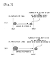
- Figure 7 is a diagram for explaining the behavior of the oil mist in the diffuser 32.
- the oil mist (the soot-containing oil) loses the oil component inside the oil mist and is reduced in the particle size, while flowing through the diffuser 32.
- the oil particle size in an inlet of the diffuser 32 is small, the flowability of the oil mist is lost while the oil mist is flowing and the oil mist becomes a deposit ( Figure 7 (A) ).
- Figure 7 (B) the oil mist passes through the diffuser 32 to reach the scroll 30 side. From this, it is found that if the oil particle size is large, the oil can be prevented from being seated on the surface of the diffuser 32, and the oil mist can be restrained from turning into a deposit.
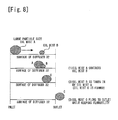
- FIG 8 is a diagram for explaining a behavior of oil mist of a large particle size (referred to the oil mist having a particle size larger than 1 ⁇ m. The same shall apply hereinafter.) in the diffuser 32.
- oil mist A oil mist
- oil mist B oil mist
- oil mist C oil mist C which has a larger particle size is formed ((2) in Figure 8 ).
- the oil mist C flows to an outlet of the diffuser 32 while keeping flowability ((3) in Figure 8 ). From this, it is found that the oil mist with a large particle size can remove the oil mist which is seated or the like.
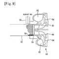
- Figure 9 is a view for explaining a flow of a blow-by gas and the like in a conventional intake system structure.
- the conventional intake system structure is similar to the intake system structure of the present embodiment except that the tubular member 34 is not installed. Therefore, the detailed description concerning the components in Figure 9 will be omitted.
- the blow-by gas which flows into an intake pipe 52 from a PCV pipe 50 flows to an inlet section 54 side together with an intake gas that flows in the intake pipe 52.
- the blow-by gas collides with an inner circumferential wall of the intake pipe 52.
- part of the oil mist in the blow-by gas is brought into a liquefied state (an oil droplet 56).
- the oil droplet 56 takes in oil mist in the blow-by gas which flows into the intake pipe 52 in succession, and moves to the inlet section 54 side in accordance with the flow of the intake gas while keeping the liquefied state.
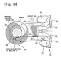
- Figure 10 is a view for explaining a behavior of the oil droplet 56 inside a compressor 58.
- the oil droplet 56 moves to the inlet section 54 side in accordance with the flow of the intake gas while keeping the liquefied state. Therefore, the oil droplet 56 which flows in from the inlet section 54 flows in from a part of a surface of an impeller 60, and is discharged to a diffuser 64 side. Accordingly, as shown in Figure 10 , a surface of the diffuser 64 is washed along a locus that the oil droplet 56 draws. In other words, in the intake system structure in Figure 9 , the surface of the diffuser 64 can be washed only partially.
- the oil droplet 38 described with Figure 3 to Figure 5 is an aggregate of oil mist with a particle size much larger than that of the oil mist with the large particle size. Therefore, by the oil droplet 38, the oil mist which is seated on the surface of the impeller 22 and deposits can be uniformly washed. Consequently, according to the intake system structure in Figure 2 , deposit accumulation in the entire surface of the diffuser 32 can be restrained. Further, the oil droplet 38 can reach the scroll 30 side without being seated on the surface of the diffuser 32. Consequently, according to the intake system structure in Figure 2 , generation of deposits in the entire surface of the diffuser 32 can be also restrained.
- the blow-by gas is caused to collide with the tubular member 34 to generate the oil droplet 38, and the generated oil droplet 38 is caused to flow along the outer circumferential wall of the tubular member 34.
- the oil droplet 38 can be also generated and caused to flow by using means other than the tubular member 34.
- Figure 11 is a view for explaining a modified mode of embodiment 1 described above.
- a blow-by gas is caused to collide with the tubular member 40 to generate the oil droplet 38, and the oil droplet 38 can be also caused to flow in such a manner as to be along the outer circumferential wall ((A) in Figure 11 ).
- a gas throttle member (liquefaction promoting member) 41 that is provided at an outlet at the intake pipe 16 side, of the PCV pipe 20, can also be used in combination with a tubular member 42 including a lower portion in the vertical direction of the tubular member 34 cut out on a larger scale than the cutout of the above described tubular member 40 ((B) in Figure 11 ).
- the above described gas throttle member 41 is more specifically a member in a truncated cone tube shape, and a member in which an end portion with a large diameter is connected to a connection region of the PCV pipe 20 and the intake pipe 16, and an end portion with a small diameter is located inside the intake pipe 16.
- a gas collision member (liquefaction promoting member) 43 provided at the connection region of the PCV pipe 20 and the intake pipe 16, and a tubular member 44 formed by cutting out a substantially right half of the tubular member 34 can be used in combination ((C) in Figure 11 ).
- the above described gas collision member 43 is a member that extends from a part of the connection region of the PCV pipe 20 and the intake pipe 16 toward a center axis of the PCV pipe 20 and toward the inside of the intake pipe 16, and the above described tubular member 44 is a member that passes a lower side of an opening of the PCV pipe 20 from an end portion in the intake pipe 16, of the above described gas collision member 43 to extend to a lower region in the vertical direction of the intake pipe 16 along the inner circumferential surface of the intake pipe 16.
- a tubular member 45 having a tube diameter smaller than that of the tubular member 40, and a tubular member 46 in a shape formed by cutting out an upper portion of the tubular member 40 can be also used in combination ((D) in Figure 11 ).
- oil droplets 38c, 38d, 38e and 38f shown in Figure 11 schematically show temporary accumulation state of the oil droplet 38.
- the tubular member 34 and the intake pipe 16 are disposed so that center axes of both of them correspond to each other. However, these center axes do not always have to correspond to each other. Namely, as shown in (B) in Figure 11 , the tubular member 34 and the intake pipe 16 may be disposed so that the center axis of the tubular member 34 is at a lower side in the gravitation direction with respect to the center axis of the intake pipe 16.
- any means that can cause oil to flow along the inner circumferential wall of the intake pipe 16 while enlarging the particle size of the oil in the blow-by gas can be used in place of the tubular member 34 of embodiment 1 described above.
- the present modification can be similarly applied in respective embodiments which will be described later.
- embodiment 1 described above explanation is made with the system including the turbocharger 12 as a premise.
- the intake system structure of embodiment 1 described above can be similarly applied in a system which is not loaded with a turbocharger. Namely, in the light of the generation mechanism of deposits, it can be said that when soot-containing oil is exposed under a high-temperature environment, the soot-containing oil easily turns into a deposit. Therefore, even in the system which is not loaded with a turbocharger, if the tubular member 34 of embodiment 1 described above is disposed in the vicinity of an intake valve (for example, an intake manifold and an intake pipe upstream of the intake manifold), the vicinity of the intake valve can be uniformly washed by the oil droplet 38. Accordingly, generation or accumulation of deposits in the vicinity of the intake valve can be restrained. Note that the present modification can be similarly applied in the respective embodiments which will be described later.
- tubular members 34 and 40 correspond to "particle size enlargement oil flowing means" in the above described first invention.
- a sectional shape perpendicular to the center axis of the tubular member 34 is circular, the sectional shape may be oval, polygonal (for example, pentagonal, hexagonal and the like).
- tubular members 34, 40, 42, 44 and 45 correspond to "intake pipe internal member" in the above described second invention.
- a feature thereof is a point in that the tubular member 34 of embodiment 1 described above is replaced with a tubular member 66 shown in Figure 12 . Therefore, hereinafter, the feature part is mainly described, and the system configuration and the other contents which are already described in embodiment 1 described above will be omitted.
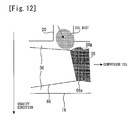
- Figure 12 is a view for explaining the feature part of the tubular member in embodiment 2, and an effect by the feature part.
- the tubular member 66 is disposed inside the intake pipe 16. Therefore, the oil droplet 38 can be generated in an outer circumferential wall of the tubular member 66.
- the PCV pipe 20 connects to the intake pipe 16 from above in the gravity direction. Therefore, the generated oil droplet 38 flows down on the outer circumferential wall of the tubular member 66 in accordance with the gravity, and diffuses to the entire outer circumferential wall while keeping a liquefied state.
- a tube port reduction section 66a is formed halfway in the tubular member 66. Therefore, in the tube port reduction section 66a, movement of the oil droplet 38 in a direction of the compressor 12b is restrained, and movement in the gravity direction (the arrow direction in the drawing) can be promoted. Thereby, a temporary accumulation state is generated (an oil droplet 38g) in the tube port reduction section 66a, and the oil droplet 38g can be caused to flow along the tube port reduction section 66a. Therefore, the oil droplet 38 can be spread over the entire outer circumferential wall of the tubular member 66.
- the tubular member 34 of embodiment 1 described above is a member in a straight-tube shape, and therefore, the oil droplet 38 is likely to be taken into the compressor 12b before the oil droplet 38 spreads over the entire outer circumferential wall of the tubular member 34.
- the oil droplet 38g in an accumulationstate is caused to flow along an outer circumference of the tube port reduction section 66a, and the oil droplet 38 can be reliably spread over the entire outer circumferential wall of the tubular member 66. Accordingly, the oil droplet 38 can be brought into contact with the surface of the diffuser 32 in a more uniform state. Accordingly, generation or accumulation of the deposits on the surface of the diffuser 32 can be restrained more effectively.
- FIG. 13 is a view for explaining a modified mode of embodiment 2 described above.
- a tubular member 68 where a groove section 68a is formed can be also used, in place of the tubular member 66.
- the groove section 68a is formed to extend around an outer circumferential wall of the tubular member 68.
- the accumulation state of the oil droplet 38 is generated (an oil droplet 38h) in the groove section 68a, and the oil droplet 38h can be caused to flow along the groove section 68a. Therefore, the oil droplet 38 can be spread over the entire outer circumferential wall of the tubular member 68. Accordingly, an effect substantially similar to the effect of embodiment 2 described above can be obtained.
- the tube port reduction section 66a and the groove section 68a correspond to "flowability reducing means" in the above described third invention.
- a feature thereof is a point in that the tubular member 34 of embodiment 1 described above is replaced with a tubular member 70 shown in Figure 14 . Therefore, hereinafter, the feature part will be mainly described, and the system configuration and the other contents which are already described in embodiment 1 described above will be omitted.
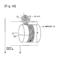
- Figure 14 is a view for explaining the feature part of the tubular member in embodiment 3, and an effect by the feature part.
- the tubular member 70 is disposed inside the intake pipe 16.
- the tubular member 70 is a tubular member in a straight tube shape similar to the tubular member 34 in Figure 2 . Therefore, an oil droplet (not illustrated) can be generated in an outer circumferential wall of the tubular member 70, and can be caused to flow on the outer circumferential wall.
- a coating section 70a formed from a lipophilic material is formed at a midpoint (more specifically, a portion immediately downstream of the connection port to the PCV pipe 20) on the outer circumferential wall of the tubular member 70.
- the coating section 70a is formed to extend in a band shape around the outer circumferential wall of the tubular member 70 with a center axis of the tubular member 70 as a center. Therefore, in the coating section 70a, movement of an oil droplet in the direction of the compressor 12b is restrained, and movement in the gravity direction (the arrow direction in the drawing) can be promoted.
- the tubular member 70 where the coating section 70a is formed is used, however, instead of forming the coating section 70a, the outer circumferential wall of the coating section formation spot may be formed by a rough surface.
- any means that can generate a temporary accumulation state of an oil droplet can be used in place of the tubular member 70 of embodiment 3 described above.
- the present modification also can be similarly applied in embodiment 4 which will be described later.
- the coating section 70a corresponds to "flowability reducing means" in the above described third invention.
- a feature thereof is a point in that the tubular member 34 of embodiment 1 described above is replaced with a tubular member 72 shown in Figure 15 . Therefore, hereinafter, the feature part will be mainly described, and the system configuration and the other contents which are already described in embodiment 1 described above will be omitted.
- Figure 15 is a view for explaining the feature part of the tubular member in embodiment 4, and an effect by the feature part.
- the tubular member 72 is disposed inside the intake pipe 16.
- the tubular member 72 is a member in a straight tube shape similar to the tubular member 34 in Figure 2 . Therefore, an oil droplet (not illustrated) can be generated in an outer circumferential wall of the tubular member 72, and can be caused to flow on the outer circumferential wall.
- coating sections 72a composed of a lipophilic material are formed along a gas flow direction.
- the coating sections 72a are formed with predetermined spaces in a circumferential direction of the tubular member 72, and among the respective coating sections 72a, the outer circumferential wall itself of the tubular member 72 is exposed. Namely, it can be said that on the outer circumferential wall of the tubular member 72, regions with high lipophilicity (the coating sections 72a) and regions with low lipophilicity (the outer circumferential wall of the tubular member 72) are alternately formed.
- tubular member By forming the tubular member like this, oil mobility to the regions with low lipophilicity from the regions with high lipophilicity is reduced, and oil accumulations can be generated in the regions with high lipophilicity. Further, since the oil accumulation has mass, the oil accumulation flows downward after a certain amount of oil is accumulated. Accordingly, oil accumulations are formed at predetermined spaces in the circumferential direction of the outer circumferential wall of the tubular member 72.
- the tubular member 72 of the present embodiment by a combination of the regions with high lipophilicity and the regions with low lipophilicity, the effects of the tubular members of embodiments 1 to 3 described above can be further enhanced. Namely, since the tubular member 34 of embodiment 1 described above is a member in a straight tube shape, the oil droplet 38 is likely to be taken into the compressor 12b before the oil droplet 38 spreads over the entire outer circumferential wall of the tubular member 34.
- the particle size of the oil droplet 38 in the accumulation state becomes excessively large, and the oil droplet 38 is likely to reach the inner circumferential wall of the intake pipe 16 at an opposite side to the connection port to the PCV pipe 20.
- Figure 16 is a view for explaining a problem of the tubular member 70 of embodiment 3 described above.
- the coating section 70a is formed on the outer circumferential wall of the tubular member 70. Therefore, the oil droplet 38 can be caused to flow along the coating section 70a.
- the oil droplet 38 finishes flowing on the coating section 70a before being taken into the compressor 12b, the oil droplet 38 is likely to accumulate on the inner circumferential wall of the intake pipe 16 as an oil droplet 38i. In that case, the oil droplet 38i flows into the compressor 12b from a part of the impeller 22, and therefore, the oil droplet 38i can only partially wash the surface of the diffuser 32.
- the tubular member 72 of the present embodiment owing to the disposition of the coating sections 72a as mentioned above, the generation amount of the oil droplet 38i described with Figure 16 can be reduced. Accordingly, the oil droplet 38 can be more effectively brought into contact with the surface of the diffuser 32 uniformly.
- tubular member 72 where the coating sections 72a are formed is used, a tubular member where groove sections are formed may be used, instead of the coating sections 72a. If the groove sections are formed along the gas flow direction, and the groove portions are formed at predetermined spaces in the circumferential direction of the tubular member, temporary oil accumulations can be generated in the groove sections. Accordingly, an effect substantially similar to the effect of embodiment 4 described above can be obtained.
- the coating section 72a corresponds to "flowability reducing means" in the above described fourth invention.
- the present embodiment has a feature of adopting an intake system structure in Figure 18 in a system configuration in Figure 17 .
- FIG 17 is a diagram for explaining the system configuration of embodiment 5.
- the system of the present embodiment includes an LPL-EGR mechanism that introduces an LPL-EGR (Low Pressure Loop Exhaust Gas Recirculation) gas.
- the LPL-EGR mechanism includes a LPL-EGR pipe 74.
- the LPL-EGR pipe 74 connects the exhaust pipe 14 at the downstream side from the turbine 12a, and the intake pipe 16 at the upstream side from the connection region of the PCV pipe 20 and the intake pipe 16.
- the configuration other than the LPL-EGR mechanism is similar to embodiment 1 described above, and therefore, explanation thereof will be omitted.
- FIG. 18 is an enlarged sectional view of a vicinity of the compressor 12b in Figure 17 .
- a tubular member 76 is disposed inside the intake pipe 16.
- the tubular member 76 is a tubular member in a straight tube shape similar to the tubular member 34 in Figure 2 . Therefore, the oil droplet 38 is generated on the outer circumferential wall of the tubular member 76, and is caused to flow on the outer circumferential wall.
- oil droplets 38j and 38k shown in Figure 18 schematically show temporary accumulation states of the oil droplet 38.
- a downstream end 76a of the tubular member 76 is disposed to face the inlet section 28. Therefore, the blow-by gas flows into the intake pipe 16 from the PCV pipe 20, flows in such a manner as to be along the outer circumferential wall (namely, the inner circumferential wall of the intake pipe 16) of the tubular member 76 together with the intake gas which flows in the gap 36, and heads toward the inlet section 28. Meanwhile, an upstream end 76b of the tubular member 76 inclines to the LPL-EGR pipe 74 side. Namely, an upstream end opening of the tubular member 76 opens toward an opening of the LPL-EGR pipe 74 to the intake pipe 16. Therefore, most of the LPL-EGR gas flows into the tubular member 76, and heads toward the inlet section 28 together with the intake gas.
- Figure 19 is a sectional view taken along line A-A' of Figure 18 .
- the blow-by gas flows in the gap 36, and the LPL-EGR gas flows inside the tubular member 76.
- the LPL-EGR gas is a gas at a high temperature (approximately 90°C).
- the temperature of the intake gas namely, an EGR gas-containing gas
- the temperature of the intake gas is a temperature higher than the gas temperature at the time of an ordinary intake gas (namely, air) reaching the discharge side 22b.
- the blow-by gas and the LPL-EGR gas mix with each other before flowing into the compressor 12b, reduction in the particle size and increase in viscosity of the soot-containing oil advance in the vicinity of the inlet section 28, and the soot-containing oil is deposited on the surface of the diffuser 32 with a high probability.
- the gases can be restrained from mixing before flowing into the compressor 12b.
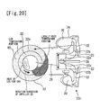
- Figure 20 is a view showing a temperature distribution inside the compressor 12b at the time of introduction of the LPL-EGR gas in the configuration which is not provided with the tubular member 76.
- the LPL-EGR gas has a high temperature, and therefore, on the surface of the diffuser 32, a locally high temperature portion is formed along the gas flow of the LPL-EGR gas.
- oil mist (soot-containing oil) flows in so as to be along the outer circumferential wall of the tubular member 76, and the LPL-EGR gas flows into the compressor 12b from the inside of the tubular member 76.
- tubular member 76 corresponds to the "internal piping" in the above described sixth invention.
Landscapes
- Engineering & Computer Science (AREA)
- Mechanical Engineering (AREA)
- General Engineering & Computer Science (AREA)
- Chemical & Material Sciences (AREA)
- Combustion & Propulsion (AREA)
- Lubrication Details And Ventilation Of Internal Combustion Engines (AREA)
- Structures Of Non-Positive Displacement Pumps (AREA)
Abstract
Description
- The present invention relates to an internal combustion engine, and more particularly relates to an internal combustion engine that is equipped with a blow-by gas returning mechanism.
- There has been conventionally known a blow-by gas returning mechanism that reintroduces a gas which flows into a crankcase from a gap between the piston and the cylinder wall surface of an internal combustion engine by way of a PCV (Positive Crankcase Ventilation) pipe and an intake pipe. For example,
Patent Literature 1 discloses the blow-by gas returning mechanism that includes a first PCV pipe which connects a cylinder head and an intake pipe, at a downstream side from a throttle valve, and a second PCV pipe which connects the cylinder head and the intake pipe at an upstream side from a compressor. According to the blow-by gas returning mechanism ofPatent Literature 1 described above, a blow-by gas is reintroduced into an internal combustion engine by two paths that are the first PCV pipe and the second PCV pipe and can be combusted. -
- Patent Literature 1: Japanese Patent Laid-Open No.
2009-293464 - Patent Literature 2: Japanese Patent Laid-Open No.
2009-281317 - Patent Literature 3: Japanese Patent Laid-Open No.
2004-116292 - Patent Literature 4: Japanese Patent Laid-Open No.
2009-264158 - Patent Literature 5: Japanese Patent Laid-Open No.
2005-048734 - Incidentally, in a blow-by gas, soot derived from carbon fuel, and oil in a crankcase are contained. Most of the oil exists in the blow-by gas with the above described soot taken inside the oil. Therefore, when the blow-by gas is introduced, the soot-containing oil contacts and adheres to the intake pipe inner wall and the other intake system components, and turns into deposits and accumulates as a result. Accumulation of deposits leads to reduction in the intake performance, and ultimately to reduction in the engine performance. Therefore, as for soot-containing oil, it is desirable that the generation of the soot-containing oil can be restrained.
- In this regard, in
Patent Literature 1 described above, a removal device that removes the oil in a blow-by gas is provided in the second PCV pipe. However, even if the removal device is used, complete removal of the oil is difficult, and the soot-containing oil flows into the intake pipe. In particular, oil mist of a particle size equal to or smaller than 1 µm (hereinafter, called "oil mist with a small particle size") is difficult to capture by the removing device, and has the property of being easily evaporated because of the small particle size in addition. Therefore, when the soot-containing oil flows into the intake pipe as oil mist with a small particle size, and contacts and adheres to the intake pipe inner wall and the like, the soot-containing oil turns into deposits with a high probability. As above, for solution to the deposits derived from the oil mist with a small particle size, further improvement has been required. - The present invention is made in the light of the aforementioned problem, and has an object to provide an internal combustion engine capable of restraining generation or accumulation of deposits derived from oil mist.
- To achieve the above described object, a first aspect of the present invention is an internal combustion engine, comprising:
- a PCV pipe that introduces a blow-by gas containing oil into an intake pipe of the internal combustion engine; and
- particle size enlargement oil flowing means for enlarging a particle size of the oil in the blow-by gas introduced into the intake pipe from the PCV pipe, and causing the oil having the particle size enlarged to flow along an inner circumferential wall of the intake pipe.
- A second aspect of the present invention is the internal combustion engine according to the first aspect,
wherein the particle size enlargement oil flowing means comprises an intake pipe internal member having an outer circumferential wall in a curved shape that is disposed on a blow-by gas passage in which the blow-by gas introduced into the intake pipe flows,
the PCV pipe is connected to the intake pipe from above in a vertical direction, and
an opening of the PCV pipe to the intake pipe, and the outer circumferential wall are disposed to face each other. - A third aspect of the present invention is the internal combustion engine according to the second aspect, further comprising:
- a compressor that is connected to the intake pipe at a downstream side from the intake pipe internal member, and compresses a gas flowing in the intake pipe.
- A fourth aspect of the present invention is the internal combustion engine according to the second or the third aspect,
wherein flowability reducing means that reduces flowability on the outer circumferential wall, of the oil in the blow-by gas introduced into the intake pipe is provided at the outer circumferential wall. - A fifth aspect of the present invention is the internal combustion engine according to the fourth aspect,
wherein the flowability reducing means is a plurality of means that extends in an upstream and downstream directions of the intake pipe, and are spaced from one another in a circumferential direction of the outer circumferential wall. - A sixth aspect of the present invention is the internal combustion engine according to any one of the second to the fifth aspects, further comprising:
- an EGR pipe that introduces an EGR gas into the intake pipe from an upstream side from an opening of the PCV pipe to the intake pipe,
- wherein the intake pipe internal member is an internal piping with a smaller diameter than the intake pipe, and
- an upstream end opening of the internal piping opens toward an opening of the EGR pipe to the intake pipe.
- According to the first invention, by the particle size enlargement oil flowing means, the oil in the blow-by gas can be caused to flow along the inner circumferential wall of the intake pipe while the particle size of the oil is enlarged. The oil mist in the blow-by gas is increased in viscosity by losing the oil component inside the oil mist, and easily adheres to the intake pipe inner wall and the like at the time of contacting the intake pipe inner wall and the like. In this regard, if the particle size of the oil can be enlarged by the particle size enlargement oil flowing means, the viscosity increasing speed can be slowed down. Accordingly, adherence of the oil mist to the intake pipe inner wall and the like can be restrained. Consequently, according to the first invention, deposit generation can be restrained. Further, the oil with an enlarged particle size in which the oil particle size is enlarged can take the oil with a small particle size inside the oil with an enlarged particle size. Therefore, if the oil with an enlarged particle size flows along the inner circumferential wall of the intake pipe, the oil with an enlarged particle size can uniformly wash and remove the oil which adheres to and is being deposited on a midpoint in the passage. Consequently, according to the first invention, accumulation of the deposits also can be restrained.
- According to the second invention, the intake pipe internal member having the outer circumferential wall in a curved shape is disposed on the blow-by gas passage, and therefore, the blow-by gas can be caused to flow along the outer circumferential wall. Further, the PCV pipe is connected to the above described intake pipe from above in the vertical direction, and further, the opening of the PCV pipe to the intake pipe, and the above described outer circumferential wall are disposed to face each other. Therefore, the above described oil with an enlarged particle size is generated on the above described outer circumferential wall, and can be caused to flow uniformly along the above described outer circumferential wall in accordance with the flow of the blow-by gas and the gravity.
- In the internal combustion engine including a compressor, the blow-by gas is compressed by the compressor. Therefore, the inside of the above described compressor can be said to be under the environment where the viscosity of the oil mist in the blow-by gas is easily increased. In this regard, according to the third invention, the intake pipe internal member having the outer circumferential wall in a curved shape is disposed on the above described blow-by gas passage at the upstream side from the compressor, and therefore, the oil with an enlarged particle size in which the oil particle size is enlarged is caused to flow uniformly along the above described outer circumferential wall and can be introduced into the above described compressor. Accordingly, generation and accumulation of deposits inside the compressor can be restrained.
- According to the fourth invention, by the flowability reducing means, flowability of the oil on the above described outer circumferential wall can be reduced. If the flowability of the oil can be reduced, enlargement of the particle size of the oil particle can be promoted before contact to the intake pipe inner wall and the like. Consequently, according to the present invention, the oil particle size can be reliably enlarged.
- As described above, the above described oil with an enlarged particle size flows along the above described outer circumferential wall in accordance with the flow of the blow-by gas and the gravity. According to the fifth invention, the above described flowability reducing means corresponds to a plurality of means which extend in the upstream and downstream directions of the above described intake pipe, and are spaced from one another along the above described outer circumferential wall, and therefore, mobility of the blow-by gas in the flow direction and mobility of the blow-by gas in the vertical direction can be balanced. Accordingly, the above described oil with an enlarged particle size can be caused to flow more uniformly along the above described outer circumferential wall.
- When the EGR pipe which introduces the EGR gas to the above described intake pipe from the upstream side from the opening of the above described PCV pipe to the above described intake pipe is included, the EGR gas is introduced into the above described intake pipe from the upstream side from the blow-by gas. Here, the EGR gas is a high-temperature gas, and therefore, if the EGR gas mixes with the blow-by gas, the oil mist in the blow-by gas easily increases in viscosity. In this regard, according to the sixth invention, the upstream end opening of the internal piping with a smaller diameter than the intake pipe is opened toward the opening of the EGR pipe to the intake pipe, and therefore, the EGR gas can be introduced into the above described internal piping. Accordingly, the EGR gas and the blow-by gas can be prevented from mixing with each other, and therefore, increase in the viscosity of the oil mist can be prevented.
-
-
Figure 1 is a diagram for explaining a system configuration ofembodiment 1. -
Figure 2 is an enlarged sectional view of a vicinity of thecompressor 12b inFigure 1 . -
Figure 3 is an enlarged sectional view of the vicinity of thecompressor 12b inFigure 1 . -
Figure 4 is a sectional view taken along line A-A inFigure 3 . -
Figure 5 is a view for explaining the behavior of theoil droplet 38 inside thecompressor 12b. -
Figure 6 is a diagram for explaining the generation mechanism of a deposit. -
Figure 7 is a diagram for explaining the behavior of the oil mist in thediffuser 32. -
Figure 8 is a diagram for explaining a behavior of oil mist of a large particle size in thediffuser 32. -
Figure 9 is a view for explaining a flow of a blow-by gas and the like in a conventional intake system structure. -
Figure 10 is a view for explaining a behavior of theoil droplet 56 inside acompressor 58. -
Figure 11 is a view for explaining a modified mode ofembodiment 1 described above. -
Figure 12 is a view for explaining the feature part of the tubular member inembodiment 2, and an effect by the feature part. -
Figure 13 is a view for explaining a modified mode ofembodiment 2. -
Figure 14 is a view for explaining the feature part of the tubular member inembodiment 3, and an effect by the feature part. -
Figure 15 is a view for explaining the feature part of the tubular member inembodiment 4, and an effect by the feature part. -
Figure 16 is a view for explaining a problem of thetubular member 70 ofembodiment 3. -
Figure 17 is a diagram for explaining the system configuration of embodiment 5. -
Figure 18 is an enlarged sectional view of a vicinity of thecompressor 12b inFigure 17 . -
Figure 19 is a sectional view taken along line A-A' ofFigure 18 . -
Figure 20 is a view showing a temperature distribution inside thecompressor 12b at the time of introduction of the LPL-EGR gas. - First, with reference to
Figure 1 to Figure 11 ,embodiment 1 of the present invention will be described.Figure 1 is a diagram for explaining a system configuration ofembodiment 1. As shown inFigure 1 , a system of the present embodiment includes anengine 10 as an internal combustion engine. Each of cylinders of theengine 10 is provided with a piston, an intake valve, an exhaust valve, fuel injector and the like. Note that the number of cylinders and disposition of the cylinders of theengine 10 are not specially limited. - Further, the system of the present embodiment includes a
turbocharger 12. Theturbocharger 12 includes aturbine 12a provided at anexhaust pipe 14, and acompressor 12b provided at anintake pipe 16. Theturbine 12a and thecompressor 12b are connected to each other. At a time of operation of theturbocharger 12, theturbine 12a receives an exhaust pressure and rotates, whereby thecompressor 12b is driven, and a gas flowing into thecompressor 12b is compressed. Theintake pipe 16 is provided with anintercooler 18 that cools the compressed gas. - Further, the system of the present embodiment includes a blow-by gas returning mechanism which returns a blow-by gas. A blow-by gas is a gas that flows into a crankcase from a gap between the piston and a cylinder wall surface of the
engine 10. The blow-by gas returning mechanism includes aPCV pipe 20. ThePCV pipe 20 connects theintake pipe 16 at an upstream side from thecompressor 12b and a cylinder head cover (not illustrated) of theengine 10. The blow-by gas flows in thePCV pipe 20 and theintake pipe 16 in this sequence, and thereby is reintroduced into theengine 10. - Next, with reference to
Figure 2 to Figure 10 , a feature of the present embodiment will be described. First, with reference toFigure 2 , a structure of an intake system corresponding to a feature part of the present embodiment will be described.Figure 2 is an enlarged sectional view of a vicinity of thecompressor 12b inFigure 1 . As shown inFigure 2 , thecompressor 12b includes animpeller 22, ahousing 24 and a connectingshaft 26. Thehousing 24 rotatably supports the connectingshaft 26 which supports theimpeller 22 to be incapable of rotating. Thehousing 24 is provided with aninlet section 28 that introduces intake air to anintake side 22a of theimpeller 22, aspiral scroll 30 that is disposed on an outer periphery of theimpeller 22, and adiffuser 32 that allows adischarge side 22b of theimpeller 22 and thescroll 30 to communicate with each other. The connectingshaft 26 is connected to a turbine wheel (not illustrated) of theturbine 12a. - Further, as shown in
Figure 2 , atubular member 34 is disposed inside theintake pipe 16. Thetubular member 34 and theintake pipe 16 are disposed in such a manner that center axes thereof correspond to each other. Thereby, agap 36 is formed between thetubular member 34 and theintake pipe 16. In order to form thegap 36 like this, as thetubular member 34, a tubular member with an outside diameter thereof having a size of 85% to approximately 99% of an inside diameter of theintake pipe 16 is preferably used. Use of thetubular member 34 of the size like this would be preferable, because oil droplets (described later) are easily caused to flow along an outer circumferential wall of thetubular member 34. Adownstream end 34a of thetubular member 34 is disposed to face theinlet section 28. - Subsequently, with reference to
Figure 3 to Figure 5 , a flow of the blow-by gas and the like in an intake system structure inFigure 2 will be described.Figure 3 is an enlarged sectional view of the vicinity of thecompressor 12b inFigure 1 . As shown by the arrows inFigure 3 , the blow-by gas which flows into theintake pipe 16 from thePCV pipe 20 flows to theinlet section 28 side together with an intake gas that flows in thegap 36. At this time, the blow-by gas collides with the outer circumferential wall of thetubular member 34, and thereafter, flows in such a manner as to be along the outer circumferential wall (an inner circumferential wall of the intake pipe 16) of thetubular member 34. - Here, as described above, oil mist that is a result of the oil in the crankcase being turned into mist is contained in the blow-by gas. The oil mist mentioned here is oil of a particle size equal to or smaller than approximately 5 µm. When the blow-by gas collides with the outer circumferential wall of the
tubular member 34, part of the oil mist in the colliding gas is liquefied (oil droplet 38). Theoil droplet 38 takes in the oil mist in the blow-by gas which flows into theintake pipe 16 in succession, and moves on the outer circumferential wall of thetubular member 34 in accordance with the flow of the intake gas and the gravity while keeping the liquefied state. Note thatoil droplets Figure 3 schematically show temporary accumulation states of theoil droplet 38. - With reference to
Figure 4 andFigure 5 , a flow of theoil droplet 38 in the intake system structure inFigure 2 will be described in detail. First, with reference toFigure 4 , a behavior of theoil droplet 38 in the outer circumferential wall of thetubular member 34 will be described.Figure 4 is a sectional view taken along line A-A inFigure 3 . As shown inFigure 4 , thePCV pipe 20 is connected to theintake pipe 16 from above in the gravitation direction (namely, above in the vertical direction). Therefore, theoil droplet 38 which is generated by collision of the blow-by gas flows down on the outer circumferential wall of thetubular member 34 in accordance with the gravity, and diffuses to the entire outer circumferential wall while keeping the liquefied state. -
Figure 5 is a view for explaining the behavior of theoil droplet 38 inside thecompressor 12b. As described inFigure 4 , theoil droplet 38 diffuses to the entire outer circumferential wall of thetubular member 34 while keeping the liquefied state. Therefore, theoil droplet 38 flows in from theinlet section 28 while keeping the liquefied state, and flows uniformly into a surface of theimpeller 22 to be discharged to thescroll 30 side. Consequently, according to the intake system structure ofFigure 2 , the surface of thediffuser 32 is washed uniformly by theoil droplet 38 which keeps the liquefied state, and generation or accumulation of deposits on the surface can be restrained. - An effect by the intake system structure in
Figure 2 described above will be described with reference toFigure 6 to Figure 10 . First, with reference toFigure 6 to Figure 8 , a generation mechanism of a deposit, and a behavior of oil mist in thediffuser 32 will be described.Figure 6 is a diagram for explaining the generation mechanism of a deposit. As described several times, the oil in the crankcase is contained in the blow-by gas. A lot of oil mist is contained in the oil. This is because the blow-by gas immediately after discharged from the cylinder head has a high temperature, and part of the oil in the blow-by gas exists in a gaseous state, and is turned into mist during flowing through thePCV pipe 20. - Further, in the oil mist, soot-containing oil which takes soot with a particle size of approximately 0.1 µm inside the soot-containing oil is present. The oil mist shown in
Figure 6 schematically shows the soot-containing oil like this. As shown inFigure 6 , the soot-containing oil flows into thecompressor 12b from the inlet section 28 ((1) inFigure 6 ). At this time, the particle size of the soot-containing oil is equal to or smaller than approximately 5 µm. Here, the gas which flows into thecompressor 12b (namely, the gas containing the intake gas and the blow-by gas) is compressed to be raised in temperature at once when passing through theimpeller 22 after passing through theinlet section 28, and is further raised in temperature in a compression region called thediffuser 32. Therefore, along with increase in temperature of the internal inflow gas, an internal temperature of the soot-containing oil also increases. Therefore, the soot-containing oil loses an oil component therein by evaporation, and the particle size of the soot-containing oil is gradually reduced. - Namely, as shown in
Figure 6 , in a vicinity of thedischarge side 22b, the soot-containing oil loses the oil component by evaporation along with increase in the temperature of the internal inflow gas, and is reduced in the particle size and is increased in viscosity ((2) inFigure 6 ). The soot-containing oil which is reduced in the particle size and increased in viscosity is seated on the surface of thediffuser 32, or further flows to a downstream side without being seated ((3) inFigure 6 ). Subsequently, the soot-containing oil which further flows to the downstream side loses most of the oil component inside the soot-containing oil ((4) inFigure 6 ). In this manner, the soot-containing oil adheres to the surface of thediffuser 32 to be a deposit. -
Figure 7 is a diagram for explaining the behavior of the oil mist in thediffuser 32. As described inFigure 6 , the oil mist (the soot-containing oil) loses the oil component inside the oil mist and is reduced in the particle size, while flowing through thediffuser 32. Especially when the oil particle size in an inlet of thediffuser 32 is small, the flowability of the oil mist is lost while the oil mist is flowing and the oil mist becomes a deposit (Figure 7 (A) ). Meanwhile, when the oil particle size is large, the flowability of the oil mist is kept high, and the oil mist passes through thediffuser 32 to reach thescroll 30 side (Figure 7 (B) ). From this, it is found that if the oil particle size is large, the oil can be prevented from being seated on the surface of thediffuser 32, and the oil mist can be restrained from turning into a deposit. -
Figure 8 is a diagram for explaining a behavior of oil mist of a large particle size (referred to the oil mist having a particle size larger than 1 µm. The same shall apply hereinafter.) in thediffuser 32. As shown inFigure 8 , when the oil mist with a large particle size (oil mist A) flows in from the inlet of thediffuser 32, the oil mist contacts oil mist (oil mist B) which is already seated or the like on the surface of the diffuser 32 ((1) inFigure 8 ). Thereupon, the oil mist B is taken in by the oil mist A, and oil mist C which has a larger particle size is formed ((2) inFigure 8 ). Subsequently, the oil mist C flows to an outlet of thediffuser 32 while keeping flowability ((3) inFigure 8 ). From this, it is found that the oil mist with a large particle size can remove the oil mist which is seated or the like. - Next, with reference to
Figure 9 to Figure 10 , supplementary explanation of the effect described withFigure 7 andFigure 8 will be given.Figure 9 is a view for explaining a flow of a blow-by gas and the like in a conventional intake system structure. Note that the conventional intake system structure is similar to the intake system structure of the present embodiment except that thetubular member 34 is not installed. Therefore, the detailed description concerning the components inFigure 9 will be omitted. - As shown in
Figure 9 , the blow-by gas which flows into anintake pipe 52 from aPCV pipe 50 flows to aninlet section 54 side together with an intake gas that flows in theintake pipe 52. At this time, the blow-by gas collides with an inner circumferential wall of theintake pipe 52. When the blow-by gas collides with the inner circumferential wall of theintake pipe 52, part of the oil mist in the blow-by gas is brought into a liquefied state (an oil droplet 56). Theoil droplet 56 takes in oil mist in the blow-by gas which flows into theintake pipe 52 in succession, and moves to theinlet section 54 side in accordance with the flow of the intake gas while keeping the liquefied state. -
Figure 10 is a view for explaining a behavior of theoil droplet 56 inside acompressor 58. As described withFigure 9 , theoil droplet 56 moves to theinlet section 54 side in accordance with the flow of the intake gas while keeping the liquefied state. Therefore, theoil droplet 56 which flows in from theinlet section 54 flows in from a part of a surface of animpeller 60, and is discharged to adiffuser 64 side. Accordingly, as shown inFigure 10 , a surface of thediffuser 64 is washed along a locus that theoil droplet 56 draws. In other words, in the intake system structure inFigure 9 , the surface of thediffuser 64 can be washed only partially. - In this regard, the
oil droplet 38 described withFigure 3 to Figure 5 is an aggregate of oil mist with a particle size much larger than that of the oil mist with the large particle size. Therefore, by theoil droplet 38, the oil mist which is seated on the surface of theimpeller 22 and deposits can be uniformly washed. Consequently, according to the intake system structure inFigure 2 , deposit accumulation in the entire surface of thediffuser 32 can be restrained. Further, theoil droplet 38 can reach thescroll 30 side without being seated on the surface of thediffuser 32. Consequently, according to the intake system structure inFigure 2 , generation of deposits in the entire surface of thediffuser 32 can be also restrained. - Incidentally, in
embodiment 1 described above, the blow-by gas is caused to collide with thetubular member 34 to generate theoil droplet 38, and the generatedoil droplet 38 is caused to flow along the outer circumferential wall of thetubular member 34. However, theoil droplet 38 can be also generated and caused to flow by using means other than thetubular member 34. -
Figure 11 is a view for explaining a modified mode ofembodiment 1 described above. For example, by using atubular member 40 in a shape formed by cutting out a lower portion in the gravity direction of thetubular member 34, in place of thetubular member 34, a blow-by gas is caused to collide with thetubular member 40 to generate theoil droplet 38, and theoil droplet 38 can be also caused to flow in such a manner as to be along the outer circumferential wall ((A) inFigure 11 ). Further, for example, a gas throttle member (liquefaction promoting member) 41 that is provided at an outlet at theintake pipe 16 side, of thePCV pipe 20, can also be used in combination with atubular member 42 including a lower portion in the vertical direction of thetubular member 34 cut out on a larger scale than the cutout of the above described tubular member 40 ((B) inFigure 11 ). Note that the above describedgas throttle member 41 is more specifically a member in a truncated cone tube shape, and a member in which an end portion with a large diameter is connected to a connection region of thePCV pipe 20 and theintake pipe 16, and an end portion with a small diameter is located inside theintake pipe 16. Further, for example, a gas collision member (liquefaction promoting member) 43 provided at the connection region of thePCV pipe 20 and theintake pipe 16, and atubular member 44 formed by cutting out a substantially right half of thetubular member 34 can be used in combination ((C) inFigure 11 ). Note that the above describedgas collision member 43 is a member that extends from a part of the connection region of thePCV pipe 20 and theintake pipe 16 toward a center axis of thePCV pipe 20 and toward the inside of theintake pipe 16, and the above describedtubular member 44 is a member that passes a lower side of an opening of thePCV pipe 20 from an end portion in theintake pipe 16, of the above describedgas collision member 43 to extend to a lower region in the vertical direction of theintake pipe 16 along the inner circumferential surface of theintake pipe 16. Furthermore, atubular member 45 having a tube diameter smaller than that of thetubular member 40, and atubular member 46 in a shape formed by cutting out an upper portion of thetubular member 40 can be also used in combination ((D) inFigure 11 ). Note thatoil droplets Figure 11 schematically show temporary accumulation state of theoil droplet 38. - Further, in
embodiment 1 described above, thetubular member 34 and theintake pipe 16 are disposed so that center axes of both of them correspond to each other. However, these center axes do not always have to correspond to each other. Namely, as shown in (B) inFigure 11 , thetubular member 34 and theintake pipe 16 may be disposed so that the center axis of thetubular member 34 is at a lower side in the gravitation direction with respect to the center axis of theintake pipe 16. - As above, any means that can cause oil to flow along the inner circumferential wall of the
intake pipe 16 while enlarging the particle size of the oil in the blow-by gas can be used in place of thetubular member 34 ofembodiment 1 described above. Note that the present modification can be similarly applied in respective embodiments which will be described later. - Further, in
embodiment 1 described above, explanation is made with the system including theturbocharger 12 as a premise. However, the intake system structure ofembodiment 1 described above can be similarly applied in a system which is not loaded with a turbocharger. Namely, in the light of the generation mechanism of deposits, it can be said that when soot-containing oil is exposed under a high-temperature environment, the soot-containing oil easily turns into a deposit. Therefore, even in the system which is not loaded with a turbocharger, if thetubular member 34 ofembodiment 1 described above is disposed in the vicinity of an intake valve (for example, an intake manifold and an intake pipe upstream of the intake manifold), the vicinity of the intake valve can be uniformly washed by theoil droplet 38. Accordingly, generation or accumulation of deposits in the vicinity of the intake valve can be restrained. Note that the present modification can be similarly applied in the respective embodiments which will be described later. - Note that in
embodiment 1 described above and the modified mode thereof, thetubular members gas throttle member 41 and thetubular member 42, the combination of thegas collision member 43 and thetubular member 44, and the combination of thetubular members - Further, while in
embodiment 1 described above, a sectional shape perpendicular to the center axis of thetubular member 34 is circular, the sectional shape may be oval, polygonal (for example, pentagonal, hexagonal and the like). - Further, in
embodiment 1 described above and the modified mode thereof, thetubular members - Next, with reference to
Figure 12 andFigure 13 ,embodiment 2 of the present invention will be described. In the present embodiment, a feature thereof is a point in that thetubular member 34 ofembodiment 1 described above is replaced with atubular member 66 shown inFigure 12 . Therefore, hereinafter, the feature part is mainly described, and the system configuration and the other contents which are already described inembodiment 1 described above will be omitted. -
Figure 12 is a view for explaining the feature part of the tubular member inembodiment 2, and an effect by the feature part. As shown inFigure 12 , thetubular member 66 is disposed inside theintake pipe 16. Therefore, theoil droplet 38 can be generated in an outer circumferential wall of thetubular member 66. Further, as shown inFigure 12 , thePCV pipe 20 connects to theintake pipe 16 from above in the gravity direction. Therefore, the generatedoil droplet 38 flows down on the outer circumferential wall of thetubular member 66 in accordance with the gravity, and diffuses to the entire outer circumferential wall while keeping a liquefied state. - Here, in the
tubular member 66, a tubeport reduction section 66a is formed halfway in thetubular member 66. Therefore, in the tubeport reduction section 66a, movement of theoil droplet 38 in a direction of thecompressor 12b is restrained, and movement in the gravity direction (the arrow direction in the drawing) can be promoted. Thereby, a temporary accumulation state is generated (anoil droplet 38g) in the tubeport reduction section 66a, and theoil droplet 38g can be caused to flow along the tubeport reduction section 66a. Therefore, theoil droplet 38 can be spread over the entire outer circumferential wall of thetubular member 66. In this regard, thetubular member 34 ofembodiment 1 described above is a member in a straight-tube shape, and therefore, theoil droplet 38 is likely to be taken into thecompressor 12b before theoil droplet 38 spreads over the entire outer circumferential wall of thetubular member 34. - As above, according to the
tubular member 66 of the present embodiment, theoil droplet 38g in an accumulationstate is caused to flow along an outer circumference of the tubeport reduction section 66a, and theoil droplet 38 can be reliably spread over the entire outer circumferential wall of thetubular member 66. Accordingly, theoil droplet 38 can be brought into contact with the surface of thediffuser 32 in a more uniform state. Accordingly, generation or accumulation of the deposits on the surface of thediffuser 32 can be restrained more effectively. - Incidentally, while in
embodiment 2 described above, thetubular member 66 where the tubeport reduction section 66a is formed is used, a tubular member where work other than the tubeport reduction section 66a is applied can be also used.Figure 13 is a view for explaining a modified mode ofembodiment 2 described above. For example, atubular member 68 where agroove section 68a is formed can be also used, in place of thetubular member 66. Note that thegroove section 68a is formed to extend around an outer circumferential wall of thetubular member 68. According to thetubular member 68, the accumulation state of theoil droplet 38 is generated (anoil droplet 38h) in thegroove section 68a, and theoil droplet 38h can be caused to flow along thegroove section 68a. Therefore, theoil droplet 38 can be spread over the entire outer circumferential wall of thetubular member 68. Accordingly, an effect substantially similar to the effect ofembodiment 2 described above can be obtained. - Note that in
embodiment 2 described above and the modified mode thereof, the tubeport reduction section 66a and thegroove section 68a correspond to "flowability reducing means" in the above described third invention. - Next, with reference to
Figure 14 ,embodiment 3 of the present invention will be described. In the present embodiment, a feature thereof is a point in that thetubular member 34 ofembodiment 1 described above is replaced with atubular member 70 shown inFigure 14 . Therefore, hereinafter, the feature part will be mainly described, and the system configuration and the other contents which are already described inembodiment 1 described above will be omitted. -
Figure 14 is a view for explaining the feature part of the tubular member inembodiment 3, and an effect by the feature part. As shown inFigure 14 , thetubular member 70 is disposed inside theintake pipe 16. Thetubular member 70 is a tubular member in a straight tube shape similar to thetubular member 34 inFigure 2 . Therefore, an oil droplet (not illustrated) can be generated in an outer circumferential wall of thetubular member 70, and can be caused to flow on the outer circumferential wall. - Further, as shown in
Figure 14 , acoating section 70a formed from a lipophilic material is formed at a midpoint (more specifically, a portion immediately downstream of the connection port to the PCV pipe 20) on the outer circumferential wall of thetubular member 70. Note that thecoating section 70a is formed to extend in a band shape around the outer circumferential wall of thetubular member 70 with a center axis of thetubular member 70 as a center. Therefore, in thecoating section 70a, movement of an oil droplet in the direction of thecompressor 12b is restrained, and movement in the gravity direction (the arrow direction in the drawing) can be promoted. Thereby, a temporary accumulation state of the oil droplet is generated in thecoating section 70a, and the oil droplet can be caused to flow along thecoating section 70a. Therefore, the oil droplet can be spread over the entire outer circumferential wall of thetubular member 70. Consequently, according to thetubular member 70 of the present embodiment, an effect substantially similar toembodiment 2 described above can be obtained. - Incidentally, in
embodiment 3 mentioned above, thetubular member 70 where thecoating section 70a is formed is used, however, instead of forming thecoating section 70a, the outer circumferential wall of the coating section formation spot may be formed by a rough surface. As above, any means that can generate a temporary accumulation state of an oil droplet can be used in place of thetubular member 70 ofembodiment 3 described above. Note that the present modification also can be similarly applied inembodiment 4 which will be described later. - Note that in
embodiment 3 described above and the modified mode thereof, thecoating section 70a corresponds to "flowability reducing means" in the above described third invention. - Next, with reference to
Figure 15 ,embodiment 4 of the present invention will be described. In the present embodiment, a feature thereof is a point in that thetubular member 34 ofembodiment 1 described above is replaced with atubular member 72 shown inFigure 15 . Therefore, hereinafter, the feature part will be mainly described, and the system configuration and the other contents which are already described inembodiment 1 described above will be omitted. -
Figure 15 is a view for explaining the feature part of the tubular member inembodiment 4, and an effect by the feature part. As shown inFigure 15 , thetubular member 72 is disposed inside theintake pipe 16. Thetubular member 72 is a member in a straight tube shape similar to thetubular member 34 inFigure 2 . Therefore, an oil droplet (not illustrated) can be generated in an outer circumferential wall of thetubular member 72, and can be caused to flow on the outer circumferential wall. - Further, as shown in
Figure 15 , on the outer circumferential wall of thetubular member 72,coating sections 72a composed of a lipophilic material are formed along a gas flow direction. Thecoating sections 72a are formed with predetermined spaces in a circumferential direction of thetubular member 72, and among therespective coating sections 72a, the outer circumferential wall itself of thetubular member 72 is exposed. Namely, it can be said that on the outer circumferential wall of thetubular member 72, regions with high lipophilicity (thecoating sections 72a) and regions with low lipophilicity (the outer circumferential wall of the tubular member 72) are alternately formed. By forming the tubular member like this, oil mobility to the regions with low lipophilicity from the regions with high lipophilicity is reduced, and oil accumulations can be generated in the regions with high lipophilicity. Further, since the oil accumulation has mass, the oil accumulation flows downward after a certain amount of oil is accumulated. Accordingly, oil accumulations are formed at predetermined spaces in the circumferential direction of the outer circumferential wall of thetubular member 72. - As above, according to the
tubular member 72 of the present embodiment, by a combination of the regions with high lipophilicity and the regions with low lipophilicity, the effects of the tubular members ofembodiments 1 to 3 described above can be further enhanced. Namely, since thetubular member 34 ofembodiment 1 described above is a member in a straight tube shape, theoil droplet 38 is likely to be taken into thecompressor 12b before theoil droplet 38 spreads over the entire outer circumferential wall of thetubular member 34. Further, with thetubular members embodiments oil droplet 38 in the accumulation state becomes excessively large, and theoil droplet 38 is likely to reach the inner circumferential wall of theintake pipe 16 at an opposite side to the connection port to thePCV pipe 20. -
Figure 16 is a view for explaining a problem of thetubular member 70 ofembodiment 3 described above. As shown inFigure 16 , on the outer circumferential wall of thetubular member 70, thecoating section 70a is formed. Therefore, theoil droplet 38 can be caused to flow along thecoating section 70a. However, when theoil droplet 38 finishes flowing on thecoating section 70a before being taken into thecompressor 12b, theoil droplet 38 is likely to accumulate on the inner circumferential wall of theintake pipe 16 as anoil droplet 38i. In that case, theoil droplet 38i flows into thecompressor 12b from a part of theimpeller 22, and therefore, theoil droplet 38i can only partially wash the surface of thediffuser 32. - In this regard, according to the
tubular member 72 of the present embodiment, owing to the disposition of thecoating sections 72a as mentioned above, the generation amount of theoil droplet 38i described withFigure 16 can be reduced. Accordingly, theoil droplet 38 can be more effectively brought into contact with the surface of thediffuser 32 uniformly. - Incidentally, while in
embodiment 4 described above, thetubular member 72 where thecoating sections 72a are formed is used, a tubular member where groove sections are formed may be used, instead of thecoating sections 72a. If the groove sections are formed along the gas flow direction, and the groove portions are formed at predetermined spaces in the circumferential direction of the tubular member, temporary oil accumulations can be generated in the groove sections. Accordingly, an effect substantially similar to the effect ofembodiment 4 described above can be obtained. - Note that in
embodiment 4 described above and the modified mode thereof, thecoating section 72a corresponds to "flowability reducing means" in the above described fourth invention. - Next, with reference to
Figure 17 to Figure 20 , embodiment 5 of the present invention will be described. The present embodiment has a feature of adopting an intake system structure inFigure 18 in a system configuration inFigure 17 . -
Figure 17 is a diagram for explaining the system configuration of embodiment 5. As shown inFigure 17 , the system of the present embodiment includes an LPL-EGR mechanism that introduces an LPL-EGR (Low Pressure Loop Exhaust Gas Recirculation) gas. The LPL-EGR mechanism includes a LPL-EGR pipe 74. The LPL-EGR pipe 74 connects theexhaust pipe 14 at the downstream side from theturbine 12a, and theintake pipe 16 at the upstream side from the connection region of thePCV pipe 20 and theintake pipe 16. The configuration other than the LPL-EGR mechanism is similar toembodiment 1 described above, and therefore, explanation thereof will be omitted. - Next, with reference to
Figure 18 to Figure 20 , the feature of the present embodiment will be described. First, with reference toFigure 18 , an intake system structure corresponding to the feature part of the present embodiment, and a flow of a blow-by gas and the like in the intake system structure will be described.Figure 18 is an enlarged sectional view of a vicinity of thecompressor 12b inFigure 17 . As shown inFigure 18 , atubular member 76 is disposed inside theintake pipe 16. Thetubular member 76 is a tubular member in a straight tube shape similar to thetubular member 34 inFigure 2 . Therefore, theoil droplet 38 is generated on the outer circumferential wall of thetubular member 76, and is caused to flow on the outer circumferential wall. Note thatoil droplets Figure 18 schematically show temporary accumulation states of theoil droplet 38. - A
downstream end 76a of thetubular member 76 is disposed to face theinlet section 28. Therefore, the blow-by gas flows into theintake pipe 16 from thePCV pipe 20, flows in such a manner as to be along the outer circumferential wall (namely, the inner circumferential wall of the intake pipe 16) of thetubular member 76 together with the intake gas which flows in thegap 36, and heads toward theinlet section 28. Meanwhile, anupstream end 76b of thetubular member 76 inclines to the LPL-EGR pipe 74 side. Namely, an upstream end opening of thetubular member 76 opens toward an opening of the LPL-EGR pipe 74 to theintake pipe 16. Therefore, most of the LPL-EGR gas flows into thetubular member 76, and heads toward theinlet section 28 together with the intake gas. - Next, an effect by the intake system structure in
Figure 18 mentioned above will be described with reference toFigure 19 to Figure 20 .Figure 19 is a sectional view taken along line A-A' ofFigure 18 . As shown inFigure 19 , the blow-by gas flows in thegap 36, and the LPL-EGR gas flows inside thetubular member 76. Here, the LPL-EGR gas is a gas at a high temperature (approximately 90°C). Accordingly, the temperature of the intake gas (namely, an EGR gas-containing gas) at the time of reaching thedischarge side 22b of theimpeller 22 is a temperature higher than the gas temperature at the time of an ordinary intake gas (namely, air) reaching thedischarge side 22b. Therefore, when the blow-by gas and the LPL-EGR gas mix with each other before flowing into thecompressor 12b, reduction in the particle size and increase in viscosity of the soot-containing oil advance in the vicinity of theinlet section 28, and the soot-containing oil is deposited on the surface of thediffuser 32 with a high probability. In this regard, according to the intake system structure inFigure 18 , the gases can be restrained from mixing before flowing into thecompressor 12b. -
Figure 20 is a view showing a temperature distribution inside thecompressor 12b at the time of introduction of the LPL-EGR gas in the configuration which is not provided with thetubular member 76. As described above, the LPL-EGR gas has a high temperature, and therefore, on the surface of thediffuser 32, a locally high temperature portion is formed along the gas flow of the LPL-EGR gas. In this regard, according to the intake system structure inFigure 18 , oil mist (soot-containing oil) flows in so as to be along the outer circumferential wall of thetubular member 76, and the LPL-EGR gas flows into thecompressor 12b from the inside of thetubular member 76. Therefore, mixing of the soot-containing oil and the locally high temperature portion can be also reduced inside thecompressor 12b. Consequently, according to the intake system structure inFigure 18 , the washing effect by theoil droplet 38 can be exhibited while mixing of the soot-containing gas and the LPL-EGR gas is restrained. - Note that in embodiment 5 described above, the
tubular member 76 corresponds to the "internal piping" in the above described sixth invention. -
- 10 engine
- 12 turbocharger
- 12a turbine
- 12b compressor
- 16, 52 intake pipe
- 20, 50 PCV pipe
- 22, 60 impeller
- 22a intake side
- 22b discharge side
- 32, 64 diffuser
- 34, 40, 42, 44, 45, 66, 68, 70, 76 tubular member
- 34a, 76a downstream end
- 36 gap
- 38,56 oil droplet
- 41 gas throttle member
- 43 gas collision member
- 66a tube port reduction section
- 68a groove section
- 70a, 72a coating section
- 74 LPL-EGR pipe
- 76b upstream end
Claims (6)
- An internal combustion engine, comprising:a PCV pipe that introduces a blow-by gas containing oil into an intake pipe of the internal combustion engine; andparticle size enlargement oil flowing means for enlarging a particle size of the oil in the blow-by gas introduced into the intake pipe from the PCV pipe, and causing the oil having the particle size enlarged to flow along an inner circumferential wall of the intake pipe.
- The internal combustion engine according to claim 1,
wherein the particle size enlargement oil flowing means comprises an intake pipe internal member having an outer circumferential wall in a curved shape that is disposed on a blow-by gas passage in which the blow-by gas introduced into the intake pipe flows,
the PCV pipe is connected to the intake pipe from above in a vertical direction, and
an opening of the PCV pipe to the intake pipe, and the outer circumferential wall are disposed to face each other. - The internal combustion engine according to claim 2, further comprising:a compressor that is connected to the intake pipe at a downstream side from the intake pipe internal member, and compresses a gas flowing in the intake pipe.
- The internal combustion engine according to claim 2 or 3,
wherein flowability reducing means that reduces flowability on the outer circumferential wall, of the oil in the blow-by gas introduced into the intake pipe is provided at the outer circumferential wall. - The internal combustion engine according to claim 4,
wherein the flowability reducing means is a plurality of means that extends in an upstream and downstream directions of the intake pipe, and are spaced from one another in a circumferential direction of the outer circumferential wall. - The internal combustion engine according to any one of claims 2 to 5, further comprising:an EGR pipe that introduces an EGR gas into the intake pipe from an upstream side from an opening of the PCV pipe to the intake pipe,wherein the intake pipe internal member is an internal piping with a smaller diameter than the intake pipe, andan upstream end opening of the internal piping opens toward an opening of the EGR pipe to the intake pipe.
Applications Claiming Priority (1)
| Application Number | Priority Date | Filing Date | Title |
|---|---|---|---|
| PCT/JP2012/061760 WO2013168232A1 (en) | 2012-05-08 | 2012-05-08 | Internal combustion engine |
Publications (2)
| Publication Number | Publication Date |
|---|---|
| EP2848781A1 true EP2848781A1 (en) | 2015-03-18 |
| EP2848781A4 EP2848781A4 (en) | 2015-04-22 |
Family
ID=49550317
Family Applications (1)
| Application Number | Title | Priority Date | Filing Date |
|---|---|---|---|
| EP12876521.1A Withdrawn EP2848781A4 (en) | 2012-05-08 | 2012-05-08 | INTERNAL COMBUSTION ENGINE |
Country Status (5)
| Country | Link |
|---|---|
| US (1) | US20150136096A1 (en) |
| EP (1) | EP2848781A4 (en) |
| JP (1) | JP5979226B2 (en) |
| CN (1) | CN104271904B (en) |
| WO (1) | WO2013168232A1 (en) |
Families Citing this family (7)
| Publication number | Priority date | Publication date | Assignee | Title |
|---|---|---|---|---|
| DE102013112771A1 (en) * | 2013-11-19 | 2015-05-21 | Rolls-Royce Deutschland Ltd & Co Kg | Jet engine with a device for spraying oil |
| DE102013112773A1 (en) | 2013-11-19 | 2015-05-21 | Rolls-Royce Deutschland Ltd & Co Kg | Jet engine with a device for injecting oil into an air-oil volume flow |
| US9926891B2 (en) * | 2015-11-18 | 2018-03-27 | General Electric Company | System and method of exhaust gas recirculation |
| JP2017190684A (en) * | 2016-04-12 | 2017-10-19 | 株式会社豊田自動織機 | Blow-by gas reduction device |
| US11261767B2 (en) * | 2019-11-12 | 2022-03-01 | Fca Us Llc | Bifurcated air induction system for turbocharged engines |
| US11415141B1 (en) * | 2021-03-03 | 2022-08-16 | GM Global Technology Operations LLC | Centrifugal compressor having positive crankcase ventilation tube extending through compressor housing to avoid high crankcase pressure |
| US12071872B1 (en) | 2023-03-06 | 2024-08-27 | GM Global Technology Operations LLC | Compressor housing PCV for reducing crankcase pressure |
Family Cites Families (34)
| Publication number | Priority date | Publication date | Assignee | Title |
|---|---|---|---|---|
| US552979A (en) * | 1896-01-14 | Joseph baker | ||
| CA1249191A (en) * | 1984-07-18 | 1989-01-24 | Yoshikazu Noguchi | Intake manifold for internal combustion engine having exhaust gas recirculation system |
| US4672939A (en) * | 1984-07-18 | 1987-06-16 | Toyota Jidosha Kabushiki Kaisha | Intake manifold for internal combustion engine having exhaust gas recirculation system |
| US4676717A (en) * | 1985-05-22 | 1987-06-30 | Cummins Atlantic, Inc. | Compressor housing having replaceable inlet throat and method for manufacturing compressor housing |
| US4724807A (en) * | 1986-03-24 | 1988-02-16 | Walker Robert A | In-line air-oil separator |
| US5572979A (en) * | 1995-07-05 | 1996-11-12 | Ford Motor Company | Engine air induction system |
| JPH09317569A (en) * | 1996-05-22 | 1997-12-09 | Nippon Soken Inc | Engine gas recirculation system |
| JPH11117722A (en) * | 1997-10-20 | 1999-04-27 | Honda Motor Co Ltd | Blow-by gas recirculation device |
| JP3669470B2 (en) * | 1998-04-10 | 2005-07-06 | 本田技研工業株式会社 | Air cleaner |
| JP4089008B2 (en) * | 1998-04-27 | 2008-05-21 | 株式会社デンソー | Blow-by gas reduction structure |
| JP2001246216A (en) * | 1999-12-28 | 2001-09-11 | Denso Corp | Gas-liquid separation device |
| US6739177B2 (en) * | 2001-03-05 | 2004-05-25 | Toyota Jidosha Kabushiki Kaisha | Combustible-gas sensor, diagnostic device for intake-oxygen concentration sensor, and air-fuel ratio control device for internal combustion engines |
| JP2004116292A (en) | 2002-09-24 | 2004-04-15 | Kubota Corp | Engine with turbocharger |
| JP4075051B2 (en) * | 2003-02-06 | 2008-04-16 | 株式会社デンソー | Intake device |
| JP4280578B2 (en) | 2003-07-31 | 2009-06-17 | トヨタ自動車株式会社 | Intake air intake system for internal combustion engine |
| US7204241B2 (en) * | 2004-08-30 | 2007-04-17 | Honeywell International, Inc. | Compressor stage separation system |
| US7278412B2 (en) * | 2005-03-31 | 2007-10-09 | Caterpillar Inc. | Combustion-gas recirculation system |
| JP4581829B2 (en) * | 2005-05-10 | 2010-11-17 | トヨタ自動車株式会社 | Oil separator and blow-by gas reduction device |
| JP2007332873A (en) * | 2006-06-15 | 2007-12-27 | Aisan Ind Co Ltd | Blow-by gas trap equipment |
| JP4299346B2 (en) * | 2007-02-14 | 2009-07-22 | トヨタ自動車株式会社 | Intake device for internal combustion engine |
| JP2008240521A (en) * | 2007-03-23 | 2008-10-09 | Honda Motor Co Ltd | Intake air amount control device for internal combustion engine |
| JP2008255960A (en) * | 2007-04-09 | 2008-10-23 | Toyota Motor Corp | Supercharging system |
| US20090090337A1 (en) * | 2007-10-05 | 2009-04-09 | Aisan Kogyo Kabushiki Kaisha | Engine blow-by gas returning apparatus |
| GB0724701D0 (en) * | 2007-12-18 | 2008-01-30 | Cummins Turbo Tech Ltd | Compressor |
| JP2009264158A (en) | 2008-04-23 | 2009-11-12 | Toyota Motor Corp | Intake system for internal combustion engine |
| JP2009281317A (en) | 2008-05-23 | 2009-12-03 | Toyota Motor Corp | Intake pipe structure of internal combustion engine |
| JP2009293464A (en) | 2008-06-04 | 2009-12-17 | Aisan Ind Co Ltd | Blow-by gas recirculating device for engine with supercharger |
| JP5023381B2 (en) * | 2008-09-30 | 2012-09-12 | トヨタ自動車株式会社 | Engine deposit control device |
| JP5134501B2 (en) * | 2008-10-28 | 2013-01-30 | 三菱重工業株式会社 | Gas engine lubrication system |
| KR101028552B1 (en) * | 2008-11-18 | 2011-04-11 | 기아자동차주식회사 | Blow-by gas oil separator |
| US7992551B2 (en) * | 2008-11-26 | 2011-08-09 | Toyota Motor Engineering & Manufacturing North America, Inc. | Oil capturing device having a rotary component |
| US7886727B2 (en) * | 2009-05-26 | 2011-02-15 | Ford Global Technologies, Llc | Variable venturi system and method for engine |
| JP5478399B2 (en) * | 2009-09-30 | 2014-04-23 | 株式会社クボタ | Engine blow-by gas recirculation system |
| DE102011010289A1 (en) * | 2011-02-03 | 2012-08-09 | GM Global Technology Operations LLC (n. d. Gesetzen des Staates Delaware) | Crankcase breather device for a motor vehicle |
-
2012
- 2012-05-08 JP JP2014514282A patent/JP5979226B2/en not_active Expired - Fee Related
- 2012-05-08 CN CN201280072952.3A patent/CN104271904B/en not_active Expired - Fee Related
- 2012-05-08 EP EP12876521.1A patent/EP2848781A4/en not_active Withdrawn
- 2012-05-08 US US14/399,315 patent/US20150136096A1/en not_active Abandoned
- 2012-05-08 WO PCT/JP2012/061760 patent/WO2013168232A1/en not_active Ceased
Also Published As
| Publication number | Publication date |
|---|---|
| WO2013168232A1 (en) | 2013-11-14 |
| CN104271904A (en) | 2015-01-07 |
| EP2848781A4 (en) | 2015-04-22 |
| JPWO2013168232A1 (en) | 2015-12-24 |
| JP5979226B2 (en) | 2016-08-24 |
| US20150136096A1 (en) | 2015-05-21 |
| CN104271904B (en) | 2016-11-16 |
Similar Documents
| Publication | Publication Date | Title |
|---|---|---|
| EP2848781A1 (en) | Internal combustion engine | |
| CN103534457B (en) | The intake structure of internal combustion engine | |
| JP6634092B2 (en) | Swirling flow generator for gas-liquid separation | |
| EP2342446B1 (en) | Module integrating mixer and particulate separator into a common housing and an engine breathing system having the module | |
| KR102452177B1 (en) | gas-liquid separator | |
| US20110030372A1 (en) | Egr apparatus for internal combustion engine | |
| JP2012140876A (en) | Housing structure for exhaust turbocharger | |
| US9181854B2 (en) | Turbocharger | |
| JP5708507B2 (en) | Compressor deposit cleaning device for internal combustion engine | |
| KR101855760B1 (en) | Engine system for exhausting water | |
| JP2010077833A (en) | Exhaust gas recirculation system | |
| JP5131486B2 (en) | Blowby gas gas oil separator | |
| JP2022076179A (en) | Centrifugal compressor, turbocharger, and engine system | |
| US9097221B2 (en) | Intake apparatus | |
| CN111566334A (en) | Gas-liquid separation device | |
| RU150646U1 (en) | ENGINE RELEASE SYSTEM (OPTIONS) | |
| NO20170296A1 (en) | Exhaust gas after-treatment system and internal combustion engine | |
| JP5321088B2 (en) | Lubricating oil recovery device | |
| JP6015843B2 (en) | Cooling device for a supercharger of an internal combustion engine equipped with a blow-by gas recirculation device | |
| JP5814537B2 (en) | Blowby gas recirculation system | |
| JP5569627B2 (en) | Mixing equipment | |
| JP2022070226A (en) | Vane mixer for engine exhaust system | |
| US20210340893A1 (en) | Blow-by gas recirculation device for internal combustion engine | |
| JP2014098310A (en) | Blow-by gas treatment device | |
| JP2014202195A (en) | Blow-by gas recirculation device of internal combustion engine |
Legal Events
| Date | Code | Title | Description |
|---|---|---|---|
| PUAI | Public reference made under article 153(3) epc to a published international application that has entered the european phase |
Free format text: ORIGINAL CODE: 0009012 |
|
| 17P | Request for examination filed |
Effective date: 20141031 |
|
| AK | Designated contracting states |
Kind code of ref document: A1 Designated state(s): AL AT BE BG CH CY CZ DE DK EE ES FI FR GB GR HR HU IE IS IT LI LT LU LV MC MK MT NL NO PL PT RO RS SE SI SK SM TR |
|
| AX | Request for extension of the european patent |
Extension state: BA ME |
|
| RA4 | Supplementary search report drawn up and despatched (corrected) |
Effective date: 20150319 |
|
| RIC1 | Information provided on ipc code assigned before grant |
Ipc: F01M 11/08 20060101ALI20150313BHEP Ipc: F01M 13/02 20060101ALN20150313BHEP Ipc: F01M 13/00 20060101AFI20150313BHEP |
|
| DAX | Request for extension of the european patent (deleted) | ||
| STAA | Information on the status of an ep patent application or granted ep patent |
Free format text: STATUS: EXAMINATION IS IN PROGRESS |
|
| 17Q | First examination report despatched |
Effective date: 20180126 |
|
| GRAP | Despatch of communication of intention to grant a patent |
Free format text: ORIGINAL CODE: EPIDOSNIGR1 |
|
| STAA | Information on the status of an ep patent application or granted ep patent |
Free format text: STATUS: GRANT OF PATENT IS INTENDED |
|
| INTG | Intention to grant announced |
Effective date: 20181102 |
|
| STAA | Information on the status of an ep patent application or granted ep patent |
Free format text: STATUS: THE APPLICATION IS DEEMED TO BE WITHDRAWN |
|
| 18D | Application deemed to be withdrawn |
Effective date: 20190313 |